Bistable Driving Method For Electrowetting Display And Related Electrowetting Display
ZHOU; Guofu ; et al.
U.S. patent application number 16/490962 was filed with the patent office on 2020-01-23 for bistable driving method for electrowetting display and related electrowetting display. This patent application is currently assigned to Academy of Shenzhen Guohua Optoelectronics. The applicant listed for this patent is Academy of Shenzhen Guohua Optoelectronics, Shenzhen Guohua Optoelectronics Co., Ltd.. Invention is credited to Alexander Victor HENZEN, Weijie LIN, Guofu ZHOU.
| Application Number | 20200027407 16/490962 |
| Document ID | / |
| Family ID | 59468241 |
| Filed Date | 2020-01-23 |


| United States Patent Application | 20200027407 |
| Kind Code | A1 |
| ZHOU; Guofu ; et al. | January 23, 2020 |
BISTABLE DRIVING METHOD FOR ELECTROWETTING DISPLAY AND RELATED ELECTROWETTING DISPLAY
Abstract
Provided is a bistable driving method for an electrowetting display, comprising: setting a non-selected voltage for one or more writing lines; switching a line voltage of the one or more writing lines from the non-selected voltage to a selected voltage; applying the digital voltage on at least one column of digital electrodes to be written; switching the line voltage of the one or more writing lines from the selected voltage to the non-selected voltage, and decreasing the digital voltage applied to the at least one column to a voltage less than the opening voltage; and applying the steps above to next one or more writing lines until an entire display screen is written.
| Inventors: | ZHOU; Guofu; (Shenzhen, Guangdong, CN) ; LIN; Weijie; (Guangzhou, Guangdong, CN) ; HENZEN; Alexander Victor; (Guangzhou, Guangdong, CN) | ||||||||||
| Applicant: |
|
||||||||||
|---|---|---|---|---|---|---|---|---|---|---|---|
| Assignee: | Academy of Shenzhen Guohua
Optoelectronics Shenzhen, Guangdong CN Shenzhen Guohua Optoelectronics Co., Ltd. Shenzhen, Guangdong CN |
||||||||||
| Family ID: | 59468241 | ||||||||||
| Appl. No.: | 16/490962 | ||||||||||
| Filed: | November 8, 2017 | ||||||||||
| PCT Filed: | November 8, 2017 | ||||||||||
| PCT NO: | PCT/CN2017/109839 | ||||||||||
| 371 Date: | September 4, 2019 |
| Current U.S. Class: | 1/1 |
| Current CPC Class: | G02B 26/005 20130101; G09G 2300/06 20130101; G09G 3/348 20130101 |
| International Class: | G09G 3/34 20060101 G09G003/34; G02B 26/00 20060101 G02B026/00 |
Foreign Application Data
| Date | Code | Application Number |
|---|---|---|
| Mar 9, 2017 | CN | 201710138110.8 |
Claims
1. A bistable driving method for an electrowetting display, comprising: S1: setting a non-selected voltage for one or more writing lines, the non-selected voltage being less than an opening voltage minus a digital voltage but greater than a closing voltage, wherein the opening voltage is a voltage for opening an oil film existing on an electrode surface, and the closing voltage is a voltage for closing the oil film existing on the electrode surface; S2: switching a line voltage of the one or more writing lines from the non-selected voltage to a selected voltage, the selected voltage being less than the opening voltage but greater than the opening voltage minus the digital voltage; S3: applying the digital voltage on at least one column to be written, to enable a voltage on, at least one pixel determined by the one or more writing lines and the at least one column to be written, to be greater than the opening voltage; S4: switching the line voltage of the one or more writing lines from the selected voltage to the non-selected voltage, and decreasing the digital voltage applied on the at least one column to a voltage less than the opening voltage minus the selected voltage; and S5: applying the steps S1 to S4 to next one or more writing lines until the entire display is written.
2. The bistable driving method for an electrowetting display according to claim 1, further comprising setting the voltages of all the lines and columns to 0V before performing the bistable driving.
3. The bistable driving method for an electrowetting display according to claim 1, further comprising firstly setting a line voltage of a writing line of the electrowetting display to 0V before increasing the line voltage of the line to the selected voltage.
4. The bistable driving method for an electrowetting display according to claim 2, further comprising increasing the line voltage of all the lines of the electrowetting display to the selected voltage after the step S5.
5. The bistable driving method for an electrowetting display according to claim 3, further comprising increasing the line voltage of all the lines of the electrowetting display to the selected voltage after the step S5.
6. The bistable driving method for an electrowetting display according to claim 2, further comprising: applying a pulse to the electrowetting display after the display is stabilized at the non-selected voltage, and setting the line voltage of the electrowetting display back to the non-selected voltage after applying the pulse, wherein the pulse has a length configured to not completely close a pixel and not change a pixel state during the bistable driving.
7. The bistable driving method for an electrowetting display according to claim 3, further comprising: applying a pulse to the electrowetting display after the display is stabilized at the non-selected voltage, and setting the line voltage of the electrowetting display back to the non-selected voltage after applying the pulse, wherein the pulse has a length configured to not completely close a pixel and not change a pixel state during the bistable driving.
8. The bistable driving method for an electrowetting display according to claim 6, wherein the pulse is applied line by line, and the line voltage of a line returns to the non-selected voltage immediately after the pulse is applied to the line.
9. The bistable driving method for an electrowetting display according to claim 6, wherein the pulse is applied to all lines of the electrowetting display simultaneously, and the line voltage of all the lines returns to the non-selected voltage immediately after the pulse is applied to all the lines.
10. The bistable driving method for an electrowetting display according to claim 6, wherein the pulse has a voltage of 0V.
11. The bistable driving method for an electrowetting display according to claim 8, wherein the pulse has a voltage of 0V.
12. The bistable driving method for an electrowetting display according to claim 9, wherein the pulse has a voltage of 0V.
13. The bistable driving method for an electrowetting display according to claim 6, wherein the pulse is applied to all columns of the electrowetting display simultaneously, and the digital voltage of all the columns returns to 0V immediately after the pulse is applied to all the columns.
14. An electrowetting display, comprising a plurality of common electrodes on which a line voltage of the electrowetting display is applied, and a plurality of digital electrodes on which a digital voltage of the electrowetting display is applied, wherein the line voltage is applied to an entire line of the common electrodes, and the digital voltage is applied to an entire column of the digital electrodes, and wherein the electrowetting display is controlled by the method according to claim 1.
Description
CROSS-REFERENCE TO RELATED APPLICATIONS
[0001] This application is a national phase application of International Application No. PCT/CN2017/109839, filed Nov. 8, 2017, which claims priority to CN 201710138110.8, filed Mar. 9, 2017, all of which are hereby incorporated herein by reference.
TECHNICAL FIELD
[0002] The present disclosure relates to a driving method and an electrowetting display, and more particularly, to a bistable driving method for an electrowetting display and related electrowetting display, belonging to the field of electrowetting displays.
BACKGROUND
[0003] Electrowetting displays are becoming more and more attractive due to high brightness, high contrast ratio, large viewing angle and fast switching speed. Resulting from these properties, the electrowetting displays are suitable for video application. In theory, the electrowetting displays can be grouped into transmissive type displays and reflective type displays. For a reflective electrowetting display, energy consumption can be relatively low, as backlight is not required.
[0004] An electrowetting display generally comprises a closed electrowetting unit, polar and non-polar liquids (such as water and oil) having different optical properties and contained in the unit, several electrodes (such as digital electrodes and common electrodes) for controlling the liquid contained in the unit, and a front plate and a rear reflective plate. These immiscible liquids can be displaced by applying a voltage to the electrodes. In a balance state (in which no voltage is applied to the electrodes), the polar and non-polar liquids are naturally delaminated in the closed unit, thus forming a thin film, such as an oil film. In this state, i.e., a colored state, the thin film covers a reflective area and the unit or the pixel is displayed in color or black. By applying the voltage at two ends the electrodes, the delaminated and colored state is no longer satisfactory in terms of energy, and the unit or the pixel can move the polar liquid to make the polar liquid be contacted with an electrode surface, thus pushing the oil film to a corner of the pixel. As a result, the non-polar liquid is displaced to expose a reflective or white surface below. Therefore, in this state, i.e., a white state, the unit or the pixel is displayed as white or bright. An interaction between static electricity and capillary force determines how far the non-polar liquid is displaced to a side. A detailed description of a structure of the electrowetting display refers to the Chinese patent application CN103984088A.
[0005] In other words, the electrowetting display is usually driven by applying the voltage to the electrodes, thus affecting the "wetting" of the electrode surface, i.e., a hydrophilicity of the electrode surface. A high voltage means that a large area of electrode surface is covered with water, so that the electrowetting display has a low absorbance. Until now, the electrowetting display is driven by a constant voltage applied to the digital electrodes, but the common electrodes are at ground potential. The oil film covers the electrode surface when no voltage is applied. A minimum voltage is required to open the oil film (which is partly caused by a surface tension), which is called an opening voltage. At this voltage, the surface tension is destroyed and the pixel is suddenly switched to an "opening" state. When the voltage is lowered, the pixel cannot be closed at the same voltage, but is only closed at a much lower voltage, which is called a closing voltage. This hysteresis phenomenon is usually deemed as an obstacle, and the display is operated in an area with the voltage higher than the closing voltage, displaying continuous behaviors with increased and decreased voltages. In addition, a display surface is usually designed to have a structure that reduces the surface tension to avoid this hysteresis phenomenon. Because this addressing method requires each pixel to have a separate drive electrode, an active matrix backplane is required to address a larger number of pixels. However, by making full use of this hysteresis phenomenon to drive the electrowetting display, it is possible to use only a passive matrix (thus being cheaper) structure to drive a larger array.
SUMMARY
[0006] Electrowetting displays are becoming more and more attractive due to high brightness, high contrast ratio, large viewing angle and fast switching speed. Resulting from these properties, the electrowetting displays are suitable for video application. In theory, the electrowetting displays can be grouped into transmissive type displays and reflective type displays. For a reflective electrowetting display, energy consumption can be relatively low, as backlight is not required.
[0007] An electrowetting display generally comprises a closed electrowetting unit, polar and non-polar liquids (such as water and oil) having different optical properties and contained in the unit, several electrodes (such as digital electrodes and common electrodes) for controlling the liquid contained in the unit, and a front plate and a rear reflective plate. These immiscible liquids can be displaced by applying a voltage to the electrodes. In a balance state (in which no voltage is applied to the electrodes), the polar and non-polar liquids are naturally delaminated in the closed unit, thus forming a thin film, such as an oil film. In this state, i.e., a colored state, the thin film covers a reflective area and the unit or the pixel is displayed in color or black. By applying the voltage at two ends the electrodes, the delaminated and colored state is no longer satisfactory in terms of energy, and the unit or the pixel can move the polar liquid to make the polar liquid be contacted with an electrode surface, thus pushing the oil film to a corner of the pixel. As a result, the non-polar liquid is displaced to expose a reflective or white surface below. Therefore, in this state, i.e., a white state, the unit or the pixel is displayed as white or bright. An interaction between static electricity and capillary force determines how far the non-polar liquid is displaced to a side. A detailed description of a structure of the electrowetting display refers to the Chinese patent application CN103984088A.
[0008] In other words, the electrowetting display is usually driven by applying the voltage to the electrodes, thus affecting the "wetting" of the electrode surface, i.e., a hydrophilicity of the electrode surface. A high voltage means that a large area of electrode surface is covered with water, so that the electrowetting display has a low absorbance. Until now, the electrowetting display is driven by a constant voltage applied to the digital electrodes, but the common electrodes are at ground potential. The oil film covers the electrode surface when no voltage is applied. A minimum voltage is required to open the oil film (which is partly caused by a surface tension), which is called an opening voltage. At this voltage, the surface tension is destroyed and the pixel is suddenly switched to an "opening" state. When the voltage is lowered, the pixel cannot be closed at the same voltage, but is only closed at a much lower voltage, which is called a closing voltage. This hysteresis phenomenon is usually deemed as an obstacle, and the display is operated in an area with the voltage higher than the closing voltage, displaying continuous behaviors with increased and decreased voltages. In addition, a display surface is usually designed to have a structure that reduces the surface tension to avoid this hysteresis phenomenon. Because this addressing method requires each pixel to have a separate drive electrode, an active matrix backplane is required to address a larger number of pixels. However, by making full use of this hysteresis phenomenon to drive the electrowetting display, it is possible to use only a passive matrix (thus being cheaper) structure to drive a larger array.
BRIEF DESCRIPTION OF THE DRAWINGS
[0009] FIG. 1 is a flow chart illustrating a bistable driving method for an electrowetting display according to an embodiment of the invention;
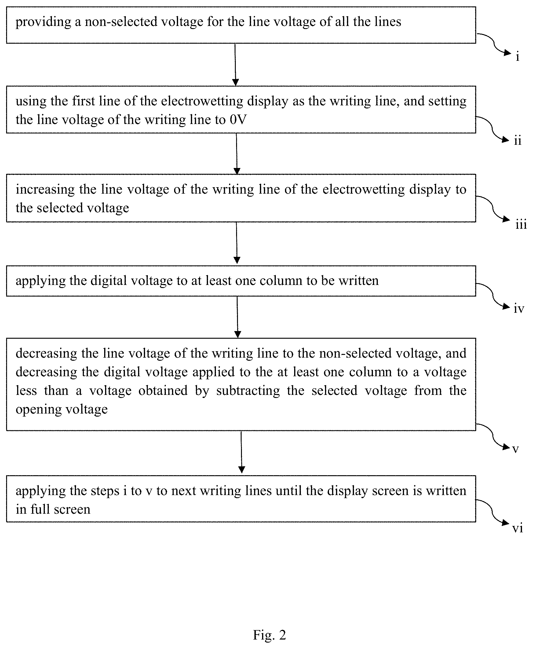
[0010] FIG. 2 is a flow chart illustrating the bistable driving method for an electrowetting display according to another embodiment of the invention;
[0011] FIG. 3 is a diagram illustrating the hysteresis effect of an electrowetting display, and the brightness adjustment of an "opened" pixel according to the hysteresis effect;
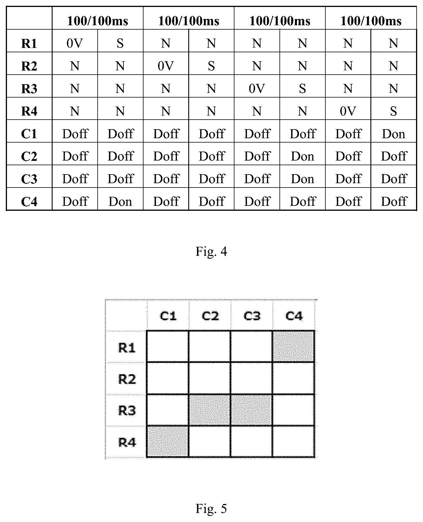
[0012] FIG. 4 illustrates a process of controlling the reset of the electrowetting display and the "opening/closing" state of the pixel according to the method of an embodiment; and
[0013] FIG. 5 is a display result corresponding to FIG. 4.
DETAILED DESCRIPTION
[0014] For electrowetting displays of different shapes and materials, a digital voltage, a non-selected voltage and a selected voltage can be set accordingly, and in addition, an opening voltage and a closing voltage result from a unit design/layer structure. To better describe the implementation process of the invention, an example that the opening voltage of the pixel of the electrowetting display is 15 V and the closing voltage of the pixel of the electrowetting display is 9 V, is taken herein. Any other voltage values capable of opening/closing the electrowetting display can also be used for the electrowetting display of different shapes and materials. The voltage for a line of the electrowetting display is applied on the common electrodes, and the voltage for a column of the electrowetting display is applied on the digital electrodes. An actual voltage at a pixel of the electrowetting display is a joint voltage of the voltages respectively applied on the common electrodes and the digital electrodes.
[0015] According to an embodiment of the invention, a bistable driving method for an electrowetting display, as shown in FIG. 1, comprises the following steps.
[0016] In S1, a non-selected voltage is set for one or more writing lines, which is less than a voltage obtained by subtracting a digital voltage from an opening voltage but greater than a closing voltage, wherein the opening voltage is a voltage for opening an oil film existing on an electrode surface, and the closing voltage is a voltage for closing the oil film existing on the electrode surface. If the opening voltage is 15V and the closing voltage is 9V, the digital voltage can be any voltages within an open interval of 0V to 6V, so that the non-selected voltage is within an open interval of 9V to 15V, and a sum of the non-selected voltage and the digital voltage is still lower than 15V, so that the electrowetting display is still in a "closing" state. For example, if the digital voltage is 2V, the non-selected voltage can be set to any voltages within an open interval of 9V to 13V, such as 12V. If the digital voltage is 3V, the non-selected voltage can be set to any voltages within an open interval of 9V to 12V, such as 11V. Since the actual opening and closing voltage in the display are slightly different from predetermined voltages, it is preferable to appropriately reduce the non-selected voltage, for example, to 1V, with respect to a feasible theoretical value. For example, when the digital voltage is 2V, theoretically the non-selected voltage can be set to any voltages within the open interval of 9V to 13V, if a right boundary of a settable interval for the non-selected voltage is reduced by 1V, then the non-selected voltage can be set to any voltages within a left-open right-closed interval of 9V to 12V, such as 11 V or 12 V. Similarly, when the digital voltage is 3 V, the non-selected voltage can be set to any voltages within a left-open right-closed interval of 9V to 11V, such as 10V or 11V. Other voltages of the non-selected voltage which are appropriately reduced by about 1V are also feasible. By appropriately setting the non-selected voltage and the digital voltage described above, the electrowetting display has excellent stability, that is, it is ensured that the actual non-selected voltage plus the digital voltage does not exceed the opening voltage, so that the electrowetting display is still in the "closing" state. Preferably, the writing lines start from a first line.
[0017] In S2, a line voltage of the one or more writing lines is switched from the non-selected voltage to a selected voltage, wherein the selected voltage is less than the opening voltage but greater than the opening voltage minus the digital voltage. For example, when the digital voltage in S2 is 2V, and the non-selected voltage is 12V, the selected voltage can be set to any voltages within an open interval of 12V to 15V, such as 13.5V, 14V or 14.5V. If the digital voltage in S2 is 3V, and the non-selected voltage remains 12V, the selected voltage can be 13 V, 14 V, etc.
[0018] In S3, the digital voltage is applied on at least one column of digital electrodes to be written, so that a voltage of at least one pixel determined by the one or more writing lines and the at least one column to be written is greater than the opening voltage.
[0019] In S4, the line voltage of the one or more writing lines is switched from the selected voltage to the non-selected voltage, and the digital voltage applied on the at least one column is decreased to a voltage less than the opening voltage minus the selected voltage.
[0020] In S5, the steps S1 to S4 are repeated to next one or more writing lines until an entire display screen is written.
[0021] The digital voltage of the at least one column in S4 is reduced to 0V.
[0022] In the case of line by line controlling the "opening/closing" state of each of pixels of the electrowetting display, a number of the digital electrodes is equal to a number of the columns of the electrowetting display, that is, the "opening/closing" state of each column of pixels is controlled by a same digital electrode. For example, when a certain pixel of a writing line needs to be in the "opening" state, these digital electrodes which are in the same columns as the pixel are applied with the digital voltage respectively, and the digital electrodes, which are in the same columns as the pixels that do not need to be in the "opening" state, are kept at 0V. When the writing line is moving to the next one or more lines, the voltage applied to all digital electrodes is first set to 0V, and the "opening/closing" state of the pixel of a new writing line is controlled in the same manner as above.
[0023] Similarly, the pixels of the electrowetting display can be "closed" by simply lowering the voltage applied to the pixels to below the closing voltage, and the bistable driving method described above can be used again once the pixels are to be "opened" again.
[0024] As an alternative solution to the embodiment above, before the bistable driving is performed, the voltages of all the lines and/or the columns are set to 0V in an erasing step. After the electrowetting display is erased each time, the bistable driving method is performed until the display is written in full screen, and then the electrowetting display is erased again for the next writing.
[0025] As an alternative solution to the embodiment above, before the line voltage of the lines is increased to the selected voltage, a line voltage of a writing line of the electrowetting display is firstly set to 0V. In this case, the bistable driving method for the electrowetting display is shown in FIG. 2, comprising the following steps:
[0026] (i) providing a non-selected voltage for the line voltage of all the lines, and the non-selected voltage is less than the opening voltage minus the digital voltage but greater than the closing voltage;
[0027] (ii) using the first line of the electrowetting display as the writing line, and setting the line voltage of the writing line to 0V;
[0028] (iii) increasing the line voltage of the writing line of the electrowetting display to the selected voltage, wherein the selected voltage is less than the opening voltage but greater than the opening voltage minus the digital voltage from;
[0029] (iv) applying the digital voltage to at least one column to be written, so that a voltage of at least one pixel determined by the writing line and the at least one column to be written is greater than the opening voltage;
[0030] (v) decreasing the line voltage of the writing line to the non-selected voltage, and decreasing the digital voltage applied to the at least one column to a voltage less than a voltage obtained by subtracting the selected voltage from the opening voltage, preferably to 0V; and
[0031] (vi) applying the steps i to v to next writing lines until the display screen is written in full screen.
[0032] That is, when a certain line of the electrowetting display needs to be written, the erasing step and the writing step are combined. In this way, the display does not need to be erased when writing in full screen, but the line written in a single line is erased. Therefore, its refresh frequency is improved. Similarly, the pixels of the electrowetting display can be "closed" by simply lowering the voltage applied to the pixels to below the closing voltage, and then the bistable driving method described above can be used again when the pixels needs to be "opened" again.
[0033] As a further improvement to the embodiment described above, after the step S5, increasing the line voltage of all the lines of the electrowetting display to the selected voltage is feasible, which maximizes a brightness of the "opened" pixels of the display, as shown FIG. 3, in which a vertical axis represents the brightness. However, for the "closed" pixels of the display, since the oil film at these pixels does not move towards corners of the pixels, the brightness of these pixels will not be affected.
[0034] In order to better describe the embodiment above, the electrowetting display comprising four lines and four columns is taken as an example, FIG. 4 illustrates a process of controlling the reset of the electrowetting display and the "opening/closing" state of the pixel according to the method of the embodiment above. Wherein, R represents lines, C represents columns, 0V represents a reset voltage, N represents the non-selected voltage, S represents the selected voltage, Doff represents the digital voltage (i.e., 0V) applied on the "closed" pixels, and Don represents the digital voltage (e.g., digital voltage, 3V) applied on the "opened" pixels. The horizontal ordinate "100/100 ms" represents that the durations of the two states of a certain pixel is 100 ms respectively. As shown in the drawing, for example, the line voltage of the first line of the electrowetting display is set to the non-selected voltage initially. To set the first pixel of the first line in the "opening" state, the line voltage of the first line is set to 0V, and the digital voltage applied to the digital electrode of the first column is kept at Doff, for 100 ms. After that, the line voltage of the first line is set to the selected voltage S, and the digital voltage applied to the digital electrode of the first column is set to Don, such that the first pixel of the first line is in the "opening" state, and this process lasts for 100 ms. Similarly, after all voltages shown in FIG. 4 are applied line by line, a display result, corresponding to FIG. 4, will be obtained, as shown in FIG. 5. In the figure, gray grids represent the pixels in the "opening" state.
[0035] Because the electrowetting display in actual implementation has a drawback that, the pixel switched into the "opening" state (i.e., the oil film is shrunk and the pixel is "clean") will gradually return to the "closing" state (even a switching voltage is continuously applied), it is usually not enough to maintain pixel switching simply by applying a continuous direct current voltage (although this case is feasible in principle).
[0036] Therefore, according to another embodiment of the present invention, after the display is full-screen written by using the bistable driving method, a pulse is applied to the electrodes of the electrowetting display, and the line voltage of the electrowetting display is set back to the non-selected voltage after the pulse is applied, wherein the pulse has a length which is short enough during the bistable driving, such that the pixel cannot be completely closed and the pixel state cannot be changed. The length of the pulse can even be as short as its visual effect is difficult to be perceived (e.g., 1 ms). The pulse can have a very low repetition frequency, e.g., once per second.
[0037] In a preferred improvement to the embodiment described above, the pulse can be applied in a following manner: after the display is addressed by using the bistable driving method, the display is stabilized at the non-selected voltage (the lines are at the non-selected voltage, and the columns are at 0V); after one second, the display is rapidly scanned at 0V (one line at a time and 1 ms for one line); and after each of the lines is addressed, the voltage of the line is immediately returned to the non-selected voltage (i.e., the 0V pulse which can be seen for 1 ms at each line).
[0038] In a preferred embodiment of the invention, the pulse can be applied in the following manner: after the display is addressed by using the bistable driving method, the display is stabilized at the non-selected voltage; and after one second, the voltages of all the lines are simply switched to 0V for 1 ms, and then immediately returned to the non-selected voltage.
[0039] In another preferred embodiment of the invention, the pulse can be applied in the following manner: after the display is addressed by using the bistable driving method, the display is stabilized at the non-selected voltage; and after one second, the voltages of all the columns are simply switched to the non-selected voltage and then immediately returned to 0V.
[0040] The voltage can be applied in various manners, to make the pulse nearly invisible. In addition, the voltage of the pulse may not have to be exactly 0V.
[0041] According to another aspect of the invention, an electrowetting display is provided, which comprises a plurality of common electrodes and a plurality of digital electrodes, a line voltage of the electrowetting display is applied to the plurality of common electrodes, and a digital voltage of the electrowetting display is applied to the plurality of digital electrodes. Specifically, the line voltage is applied to an entire line of the common electrodes, the digital voltage is applied to an entire column of the digital electrodes, and the electrowetting display is controlled by the method described above. The display of the electrowetting display can be controlled by the bistable driving method according to the implementations described in the specification. For the electrowetting display having M*N pixels, only M+N electrodes are needed for controlling the display of such an electrowetting display, this greatly simplifies the structure of electrowetting displays.
[0042] The various implementations in the disclosure are described in an exemplary way, the same and similar parts among the various implementations can be referenced to each other, and the implementations have respective focuses on different aspects. In particular, since the device embodiment is basically similar to the method embodiment, the description for the device embodiment is relatively simple, and the relevant points may refer to the partial description of the method embodiment.
[0043] The foregoing are merely the preferred implementations of the present invention, the invention should not be limited to the implementations described above, and any technical effects of the invention achieving by the same means shall fall within the protection scope of the invention. The technical solutions and/or implementations of the present invention can have various modifications and changes within the protection scope of the present disclosure. Even if individual technical features are cited in different claims, the present disclosure can also include implementations sharing these features.
[0044] Although the foregoing describes the detailed implementations of the invention with reference to the drawings, but the protection scope of the present disclosure is not limited thereto. Those skilled in the art shall understand that various modifications or variations made by those skilled in the art based on the technical solutions of the present disclosure without any creative works shall still fall within the protection scope of the present disclosure.
* * * * *
D00000
D00001
D00002
D00003
D00004
XML
uspto.report is an independent third-party trademark research tool that is not affiliated, endorsed, or sponsored by the United States Patent and Trademark Office (USPTO) or any other governmental organization. The information provided by uspto.report is based on publicly available data at the time of writing and is intended for informational purposes only.
While we strive to provide accurate and up-to-date information, we do not guarantee the accuracy, completeness, reliability, or suitability of the information displayed on this site. The use of this site is at your own risk. Any reliance you place on such information is therefore strictly at your own risk.
All official trademark data, including owner information, should be verified by visiting the official USPTO website at www.uspto.gov. This site is not intended to replace professional legal advice and should not be used as a substitute for consulting with a legal professional who is knowledgeable about trademark law.