Variable Magnification Optical System, Optical Apparatus, And Method For Producing Variable Magnification Optical System
MACHIDA; Kosuke
U.S. patent application number 16/496420 was filed with the patent office on 2020-01-23 for variable magnification optical system, optical apparatus, and method for producing variable magnification optical system. The applicant listed for this patent is Nikon Corporation. Invention is credited to Kosuke MACHIDA.
| Application Number | 20200026048 16/496420 |
| Document ID | / |
| Family ID | 63713270 |
| Filed Date | 2020-01-23 |


View All Diagrams
| United States Patent Application | 20200026048 |
| Kind Code | A1 |
| MACHIDA; Kosuke | January 23, 2020 |
VARIABLE MAGNIFICATION OPTICAL SYSTEM, OPTICAL APPARATUS, AND METHOD FOR PRODUCING VARIABLE MAGNIFICATION OPTICAL SYSTEM
Abstract
A variable magnification optical system comprising, in order from an object side, a first lens group having negative refractive power, a first intermediate lens group having positive refractive power, a second intermediate lens group having negative refractive power and a rear lens group; upon varying a magnification from a wide angle end state to a telephoto end state, a distance between the first lens group and the first intermediate lens group being varied, a distance between the first intermediate lens group and the second intermediate lens group being varied, and a distance between the second intermediate lens group and the rear lens group being varied; the rear lens group comprising at least one focusing lens group which is moved upon carrying out focusing from an infinitely distant object to a closely distant object; and predetermined conditional expressions being satisfied, thereby the focusing lens group(s) being reduced in weight.
| Inventors: | MACHIDA; Kosuke; (Tokyo, JP) | ||||||||||
| Applicant: |
|
||||||||||
|---|---|---|---|---|---|---|---|---|---|---|---|
| Family ID: | 63713270 | ||||||||||
| Appl. No.: | 16/496420 | ||||||||||
| Filed: | April 5, 2017 | ||||||||||
| PCT Filed: | April 5, 2017 | ||||||||||
| PCT NO: | PCT/JP2017/014195 | ||||||||||
| 371 Date: | September 21, 2019 |
| Current U.S. Class: | 1/1 |
| Current CPC Class: | G02B 15/177 20130101; G02B 13/18 20130101; G02B 15/20 20130101; G02B 13/02 20130101 |
| International Class: | G02B 15/20 20060101 G02B015/20; G02B 13/18 20060101 G02B013/18; G02B 13/02 20060101 G02B013/02 |
Claims
1. A variable magnification optical system comprising, in order from an object side, a first lens group having negative refractive power, a first intermediate lens group having positive refractive power, a second intermediate lens group having negative refractive power and a rear lens group; upon varying a magnification from a wide angle end state to a telephoto end state, a distance between said first lens group and said first intermediate lens group being varied, a distance between said first intermediate lens group and said second intermediate lens group being varied, and a distance between said second intermediate lens group and said rear lens group being varied; said rear lens group comprising at least one focusing lens group which is moved upon carrying out focusing from an infinite distance object to a close distance object; and the following conditional expression being satisfied: 0.050<f1/fM2<1.050 where f1 denotes a focal length of said first lens group, and fM2 denotes a focal length of said second intermediate lens group.
2. A variable magnification optical system according to claim 1, wherein the following conditional expression is satisfied: 0.70<|fF|/ft<3.30 where fF denotes a focal length of a focusing lens group having a strongest refractive power in the focusing lens groups, and ft denotes a focal length of the variable magnification optical system in the telephoto end state.
3. A variable magnification optical system according to claim 1, wherein the following conditional expression is satisfied: 0.60<f1N/f1<2.00 where f1N denotes a focal length of a lens having a strongest negative refractive power in the first lens group, and f1 denotes a focal length of the first lens group.
4. A variable magnification optical system according to claim 1, wherein the following conditional expression is satisfied: 2.00<D1Mw/fw<4.00 where D1Mw denotes a distance along the optical axis between the first lens group and the first intermediate lens group in the wide angle end state, and fw denotes a focal length of the variable magnification optical system in the wide angle end state.
5. A variable magnification optical system according to claim 1, wherein the following conditional expression is satisfied: 2.00<.nu.M1P/.nu.M1N<3.00 where .nu.M1P denotes an Abbe's number of a lens having a strongest positive refractive power in the first intermediate lens group, and .nu.M1N denotes an Abbe's number of a lens having a strongest negative refractive power in the first intermediate lens group.
6. A variable magnification optical system according to claim 1, wherein the following conditional expression is satisfied: 0.20<fM1P/fM1N<0.80 where fM1P denotes a focal length of a lens having a strongest positive refractive power in the first intermediate lens group, and fM1N denotes a focal length of a lens having a strongest negative refractive power in the first intermediate lens group.
7. A variable magnification optical system according to claim 1, wherein 38.00.degree.<.omega.w<85.00.degree. where .omega.w denotes a half angle of view of the variable magnification optical system in the wide angle end state.
8. A variable magnification optical system according to claim 1, wherein said focusing lens group is composed of one or two lenses.
9. A variable magnification optical system according to claim 1, wherein said first intermediate lens group comprises at least two lenses having negative refractive power.
10. A variable magnification optical system according to claim 1, wherein said first lens group is composed of two lens components.
11. A variable magnification optical system according to claim 1, wherein said rear lens group comprises at least one lens component at an image side of the most image side focusing lens group in said focusing lens groups.
12. A variable magnification optical system according to claim 1, wherein at least one of the focusing lens groups has positive refractive power.
13. A variable magnification optical system according to claim 1, wherein said first intermediate lens group comprises, in order from the object side, a second lens group having positive refractive power and a third lens group having positive refractive power.
14. A variable magnification optical system according to claim 1, wherein said rear lens group comprises at least two focusing lens groups.
15. An optical apparatus comprising a variable magnification optical system according to claim 1.
16. A method for manufacturing a variable magnification optical system which comprises, in order from an object side, a first lens group having negative refractive power, a first intermediate lens group having positive refractive power, a second intermediate lens group having negative refractive power and a rear lens group, comprising the steps of: constructing such that, upon varying a magnification from a wide angle end state to a telephoto end state, a distance between said first lens group and said first intermediate lens group is varied, a distance between said first intermediate lens group and said second intermediate lens group is varied, and a distance between said second intermediate lens group and said rear lens group is varied; constructing such that said rear lens group comprises at least one focusing lens group which is moved upon carrying out focusing from an infinite distance object to a close distance object; and constructing such that the following conditional expression is satisfied: 0.050<f1/fM2<1.050 where f1 denotes a focal length of said first lens group, and fM2 denotes a focal length of said second intermediate lens group.
17. A variable magnification optical system according to claim 1, wherein the following conditional expression is satisfied: 0.10<BFw/fw<1.00 where BFw denotes a back focus of said variable magnification optical system in the wide angle end state, and fw denotes a focal length of said variable magnification optical system in the wide angle end state.
Description
TECHNICAL FIELD
[0001] The present invention relates to a variable magnification optical system, an optical apparatus and a method for manufacturing the variable magnification optical system.
BACKGROUND ART
[0002] There has been proposed a variable magnification optical system that is suitable to be used for a photographic camera, an electronic still camera, a video camera or the like. For example, refer to Japanese Patent application Laid-Open Gazette No. 2013-160944. However, in the conventional variable magnification optical system a focusing lens group has not been made sufficiently light in weight.
PRIOR ART REFERENCE
Patent Document
[0003] Patent Document 1: Japanese Patent application Laid-Open Gazette No. 2013-160944.
SUMMARY OF THE INVENTION
[0004] According to the present invention, there is provided a variable magnification optical system comprising, in order from an object side, a first lens group having negative refractive power, a first intermediate lens group having positive refractive power, a second intermediate lens group having negative refractive power and a rear lens group;
[0005] upon varying a magnification from a wide angle end state to a telephoto end state, a distance between said first lens group and said first intermediate lens group being varied, a distance between said first intermediate lens group and said second intermediate lens group being varied, and a distance between said second intermediate lens group and said rear lens group being varied;
[0006] said rear lens group comprising at least one focusing lens group which is moved upon carrying out focusing from an infinitely distant object to a closely distant object; and
[0007] the following conditional expressions being satisfied:
0.050<f1/fM2<1.050
0.10<BFw/fw<1.00
[0008] where f1 denotes a focal length of said first lens group, fM2 denotes a focal length of said second intermediate lens group, BFw denotes aback focus of said variable magnification optical system in the wide angle end state, and fw denotes a focal length of said variable magnification optical system in the wide angle end state.
[0009] Further, according to the present invention, there is provided a method for manufacturing a variable magnification optical system comprising, in order from an object side, a first lens group having negative refractive power, a first intermediate lens group having positive refractive power, a second intermediate lens group having negative refractive power and a rear lens group; comprising steps of:
[0010] constructing such that, upon varying a magnification from a wide angle end state to a telephoto end state, a distance between said first lens group and said first intermediate lens group is varied, a distance between said first intermediate lens group and said second intermediate lens group is varied, and a distance between said second intermediate lens group and said rear lens group is varied;
[0011] constructing such that said rear lens group comprises at least one focusing lens group which is moved upon carrying out focusing from an infinitely distant object to a closely distant object; and constructing such that the following conditional expressions are satisfied:
0.050<f1/fM2<1.050
0.10<BFw/fw<1.00
[0012] where f1 denotes a focal length of said first lens group, fM2 denotes a focal length of said second intermediate lens group, BFw denotes aback focus of said variable magnification optical system in the wide angle end state, and fw denotes a focal length of said variable magnification optical system in the wide angle end state
BRIEF DESCRIPTION OF THE DRAWINGS
[0013] FIG. 1 is a sectional view of a variable magnification optical system according to a First Example.
[0014] FIG. 2A, FIG. 2B and FIG. 2C are graphs showing various aberrations upon focusing on an infinite distance object, respectively, in the wide angle end state, in the intermediate focal length state, and in the telephoto end state, of the variable magnification optical system according to the First Example.
[0015] FIG. 3A, FIG. 3B and FIG. 3C are graphs showing various aberrations upon focusing on a close distance object, respectively, in the wide angle end state, in the intermediate focal length state, and in the telephoto end state, of the variable magnification optical system according to the First Example.
[0016] FIG. 4 is a sectional view of a variable magnification optical system according to a Second Example.
[0017] FIG. 5A, FIG. 5B and FIG. 5C are graphs showing various aberrations upon focusing on an infinite distance object, respectively, in the wide angle end state, in the intermediate focal length state, and in the telephoto end state, of the variable magnification optical system according to the Second Example.
[0018] FIG. 6A, FIG. 6B and FIG. 6C are graphs showing various aberrations upon focusing on a close distance object, respectively, in the wide angle end state, in the intermediate focal length state, and in the telephoto end state, of the variable magnification optical system according to the Second Example.
[0019] FIG. 7 is a sectional view of a variable magnification optical system according to a Third Example.
[0020] FIG. 8A, FIG. 8B and FIG. 8C are graphs showing various aberrations upon focusing on an infinite distance object, respectively, in the wide angle end state, in the intermediate focal length state, and in the telephoto end state, of the variable magnification optical system according to the Third Example.
[0021] FIG. 9A, FIG. 9B and FIG. 9C are graphs showing various aberrations upon focusing on a close distance object, respectively, in the wide angle end state, in the intermediate focal length state, and in the telephoto end state, of the variable magnification optical system according to the Third Example.
[0022] FIG. 10 is a sectional view of a variable magnification optical system according to a Fourth Example.
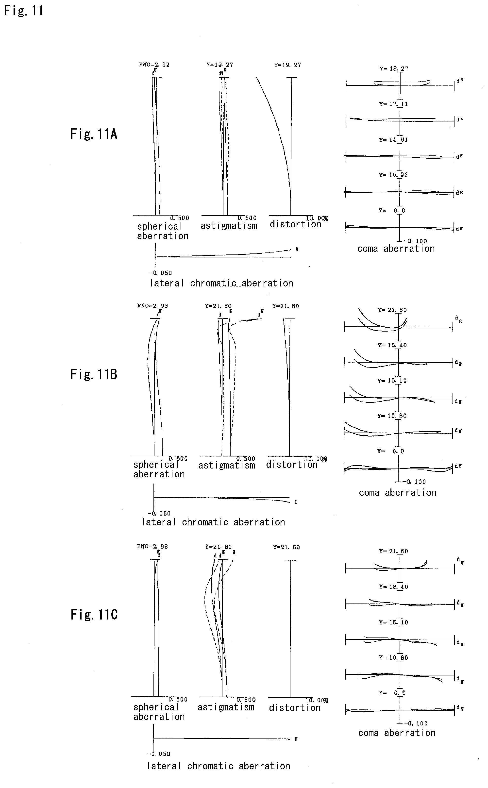
[0023] FIG. 11A, FIG. 11B and FIG. 11C are graphs showing various aberrations upon focusing on an infinite distance object, respectively, in the wide angle end state, in the intermediate focal length state, and in the telephoto end state, of the variable magnification optical system according to the Fourth Example.
[0024] FIGS. 12A, 12B and 12C are graphs showing various aberrations upon focusing on a close distance object, respectively, in the wide angle end state, in the intermediate focal length state, and in the telephoto end state, of the variable magnification optical system according to the Fourth Example.
[0025] FIG. 13 is a sectional view of a variable magnification optical system according to a Fifth Example.
[0026] FIG. 14A, FIG. 14B and FIG. 14C are graphs showing various aberrations upon focusing on an infinite distance object, respectively, in the wide angle end state, in the intermediate focal length state, and in the telephoto end state, of the variable magnification optical system according to the Fifth Example.
[0027] FIG. 15A, FIG. 15B and FIG. 15C are graphs showing various aberrations upon focusing on a close distance object, respectively, in the wide angle end state, in the intermediate focal length state, and in the telephoto end state, of the variable magnification optical system according to the Fifth Example.
[0028] FIG. 16 is a sectional view of a variable magnification optical system according to a Sixth Example.
[0029] FIG. 17A, FIG. 17B and FIG. 17C are graphs showing various aberrations upon focusing on an infinite distance object, respectively, in the wide angle end state, in the intermediate focal length state, and in the telephoto end state, of the variable magnification optical system according to the Sixth Example.
[0030] FIG. 18A, FIG. 18B and FIG. 18C are graphs showing various aberrations upon focusing on a close distance object, respectively, in the wide angle end state, in the intermediate focal length state, and in the telephoto end state, of the variable magnification optical system according to the Sixth Example.
[0031] FIG. 19 is a sectional view of a variable magnification optical system according to a Seventh Example.
[0032] FIG. 20A, FIG. 20B and FIG. 20C are graphs showing various aberrations upon focusing on an infinite distance object, respectively, in the wide angle end state, in the intermediate focal length state, and in the telephoto end state, of the variable magnification optical system according to the Seventh Example.
[0033] FIG. 21A, FIG. 21B and FIG. 21C are graphs showing various aberrations upon focusing on a close distance object, respectively, in the wide angle end state, in the intermediate focal length state, and in the telephoto end state, of the variable magnification optical system according to the Seventh Example.
[0034] FIG. 22 is a sectional view of a variable magnification optical system according to an Eighth Example.
[0035] FIG. 23A, FIG. 23B and FIG. 23C are graphs showing various aberrations upon focusing on an infinite distance object, respectively, in the wide angle end state, in the intermediate focal length state, and in the telephoto end state, of the variable magnification optical system according to the Eighth Example.
[0036] FIG. 24A, FIG. 24B and FIG. 24C are graphs showing various aberrations upon focusing on a close distance object, respectively, in the wide angle end state, in the intermediate focal length state, and in the telephoto end state, of the variable magnification optical system according to the Eighth Example.
[0037] FIG. 25 is a view showing a configuration of a camera equipped with the variable magnification optical system.
[0038] FIG. 26 is a flowchart schematically showing a method for manufacturing the variable magnification optical system.
EMBODIMENT FOR CARRYING OUT THE INVENTION
[0039] Next, a variable magnification optical system according to the present embodiment, an optical apparatus and a method for producing the variable magnification optical system, will be explained.
[0040] The variable magnification optical system according to the present embodiment comprises, in order from an object side, a first lens group having negative refractive power, a first intermediate lens group having positive refractive power, a second intermediate lens group having negative refractive power and a rear lens group;
[0041] upon varying a magnification from a wide angle end state to a telephoto end state, a distance between said first lens group and said first intermediate lens group being varied, a distance between said first intermediate lens group and said second intermediate lens group being varied, and a distance between said second intermediate lens group and said rear lens group being varied;
[0042] said rear lens group comprising at least one focusing lens group which is moved upon carrying out focusing from an infinite distance object to a close distance object; and
[0043] the following conditional expressions being satisfied:
0.050<f1/fM2<1.050 (1)
0.10<BFw/fw<1.00 (2)
[0044] where f1 denotes a focal length of said first lens group, fM2 denotes a focal length of said second intermediate lens group, BFw denotes aback focus of said variable magnification optical system in the wide angle end state, and fw denotes a focal length of said variable magnification optical system in the wide angle end state
[0045] Here, in the present embodiment, the first intermediate lens group, the second intermediate lens group and the rear lens group, each comprise at least one lens group. Meanwhile, in the present embodiment, a lens group means a portion which comprises at least one lens separated by an air space.
[0046] The variable magnification optical system according to the present embodiment comprises at least four lens groups and changes distances between the neighboring lens groups upon varying magnification from the wide angle end state to the telephoto end state, thereby being able to attain superb aberration correction upon varying magnification. Moreover, the focusing lens group(s) can be downsized and made light in weight by arranging the focusing lens group(s) in the rear lens group.
[0047] The conditional expression (1) defines a ratio of a focal length of the first lens group relative to a focal length of the second intermediate lens group. With satisfying the conditional expression (1), it is possible to suppress variations in spherical aberration and other various aberrations upon varying magnification from the wide angle end state to the telephoto end state.
[0048] When the value of f1/fM2 is equal to or exceeds the upper limit of the conditional expression (1) of the variable magnification optical system of the present application, refractive power of the second intermediate lens group becomes strong, and it becomes difficult to suppress variations in spherical aberration and other various aberrations upon varying magnification from the wide angle end state to the telephoto end state. Meanwhile, it is preferable to set the upper limit value of the conditional expression (1) to 1.00 and more preferable to 0.95.
[0049] On the other hand, when the value of f1/fM2 is equal to or falls below the lower limit of the conditional expression (1) of the variable magnification optical system of the present application, refractive power of the first lens group becomes strong, and it becomes difficult to suppress variations in spherical aberration and other various aberrations upon varying magnification from the wide angle end state to the telephoto end state. Meanwhile, it is preferable to set the lower limit value of the conditional expression (1) to 0.10 and more preferable to 0.15.
[0050] The conditional expression (2) defines a ratio of aback focus of said variable magnification optical system in the wide angle end state relative to a focal length of said variable magnification optical system in the wide angle end state. With satisfying the conditional expression (2), the variable magnification optical system according to the present embodiment can correct effectively coma aberration and other various aberrations in the wide angle end state. Meanwhile, the term "back focus" means a distance along the optical axis from the most image side lens surface to the image plane.
[0051] When the value of BFw/fw is equal to or exceeds the upper limit of the conditional expression (2) of the variable magnification optical system of the present embodiment, the back focus in the wide angle end state relative to the focal length in the wide angle end state becomes large, and it becomes difficult to correct coma aberration and other various aberrations in the wide angle end state. Meanwhile, it is preferable to set the upper limit value of the conditional expression (2) to 0.95, further preferable to 0.90 and further more preferable to 0.85, and still further preferable to 0.80.
[0052] On the other hand, when the value of BFw/fw is equal to or falls below the lower limit value of the conditional expression (2) of the variable magnification optical system of the present embodiment, the back focus in the wide angle end state relative to the focal length in the wide angle end state becomes small, and it becomes difficult to correct coma aberration and other various aberrations in the wide angle end state. It becomes difficult also to arrange mechanical members of lens barrel. Meanwhile, it is preferable to set the lower limit value of the conditional expression (2) to 0.20, further preferable to 0.25, further more preferable to 0.30 and still further preferable to 0.40.
[0053] With the above mentioned configurations, it is possible to realize the variable magnification optical system which has excellent optical performance, and in which the focusing lens group(s) is(are) made light in weight.
[0054] In the variable magnification optical system according to the present embodiment, it is desirable that the following conditional expression (3) is satisfied:
0.70<|fF|/ft<3.30 (3)
where fF denotes a focal length of a focusing lens group having a strongest refractive power in the focusing lens groups, and ft denotes a focal length of the variable magnification optical system in the telephoto end state.
[0055] The conditional expression (3) defines a ratio of a focal length of the focusing lens group having the strongest refractive power in the focusing lens groups, relative to a focal length of the variable magnification optical system in the telephoto end state.
[0056] With satisfying the conditional expression (3), the variable magnification optical system according to the present embodiment can suppress variations in spherical aberration and other various aberrations upon carrying out focusing from an infinite distance object to a close distance object, without making the lens barrel large.
[0057] When the value of |fF|/ft is equal to or exceeds the upper limit value of the conditional expression (3) of the variable magnification optical system according to the present embodiment, refractive power of the focusing lens group becomes weak, and an amount of movement of the focusing lens group upon carrying out focusing from the infinite distance object to the close distance object becomes large so that the lens barrel becomes large in size. Meanwhile, it is preferable to set the upper limit value of the conditional expression (3) to 3.20 and further preferable to 3.10.
[0058] On the other hand, when the value of |fF|/ft in the conditional expression (3) of the variable magnification optical system according to the present embodiment, is equal to or falls below the lower limit value, refractive power of the focusing lens group becomes strong, and it becomes difficult to suppress variation in spherical aberration upon carrying out focusing from the infinite distance object to the close distance object. Meanwhile, it is preferable to set the lower limit value of the conditional expression (3) to 0.75, and further preferable to 0.80.
[0059] Further, in the variable magnification optical system according to the present embodiment, it is desirable that the following conditional expression (4) is satisfied:
0.60<f1N/f1<2.20 (4)
where f1N denotes a focal length of a lens having a strongest negative refractive power in the first lens group, and f1 denotes a focal length of the first lens group.
[0060] The conditional expression (4) defines a ratio of the focal length of the lens having the strongest negative refractive power in the first lens group to the focal length of the first lens group.
[0061] With satisfying the conditional expression (4), the variable magnification optical system according to the present embodiment can correct effectively coma aberration and other various aberrations and suppress variations in spherical aberration and other various aberrations upon varying magnification from a wide angle end state to a telephoto end state.
[0062] When the value of f1N/f1 is equal to or exceeds the upper limit value of the conditional expression (4) of the variable magnification optical system according to the present embodiment, refractive power of the first lens group becomes strong, and it becomes difficult to suppress variations in spherical aberration and other various aberrations upon varying magnification from the wide angle end state to the telephoto end state. Meanwhile, it is preferable to set the upper limit value of the conditional expression (4) to 1.90 and further preferable to 1.80.
[0063] On the other hand, when the value of f1N/f1 in the conditional expression (4) of the variable magnification optical system according to the present embodiment, is equal to or falls below the lower limit value, refractive power of the lens having the strongest negative refractive power in the first lens group becomes strong, and it becomes difficult to suppress coma aberration and other various aberrations. Meanwhile, it is preferable to set the lower limit value of the conditional expression (4) to 0.70, further preferable to 0.80, and furthermore preferable to 0.90.
[0064] In the variable magnification optical system according to the present embodiment, it is desirable that the following conditional expression (5) is satisfied:
2.00<D1Mw/fw<4.00 (5)
where D1Mw denotes a distance along the optical axis between the first lens group and the first intermediate lens group in the wide angle end state, and fw denotes the focal length of the variable magnification optical system in the wide angle end state.
[0065] The conditional expression (5) defines a ratio of the distance along the optical axis between the first lens group and the first intermediate lens group in the wide angle end state to the focal length of the variable magnification optical system in the wide angle end state.
[0066] With satisfying the conditional expression (5), the variable magnification optical system according to the present embodiment can effectively correct coma aberration and other various aberrations in the wide angle end state without making the size of a lens barrel large.
[0067] When the value of D1Mw/fw is equal to or exceeds the upper limit value of the conditional expression (5) of the variable magnification optical system according to the present embodiment, the distance along the optical axis between the first lens group and the first intermediate lens group in the wide angle end state, becomes large, and thereby the size of the lens barrel becomes large. Meanwhile, it is preferable to set the upper limit value of the conditional expression (5) to 3.90 and further preferable to 3.80.
[0068] On the other hand, when the value of D1Mw/fw in the conditional expression (5) of the variable magnification optical system according to the present embodiment, is equal to or falls below the lower limit value, the distance along the optical axis between the first lens group and the first intermediate lens group in the wide angle end state, becomes small, and it becomes difficult to correct effectively coma aberration and other various aberrations in the wide angle end state. Meanwhile, it is preferable to set the lower limit value of the conditional expression (5) to 2.10, and further preferable to 2.20.
[0069] In the variable magnification optical system according to the present embodiment, it is desirable that the following conditional expression (6) is satisfied:
2.00<.nu.M1P/.nu.M1N<3.00 (6)
where .nu.M1P denotes an Abbe's number of a lens having a strongest positive refractive power in the first intermediate lens group, and .nu.M1N denotes an Abbe's number of a lens having a strongest negative refractive power in the first intermediate lens group.
[0070] The conditional expression (6) defines a ratio of the Abbe's number of the lens having the strongest positive refractive power in the first intermediate lens group to the Abbe's number of the lens having the strongest negative refractive power in the first intermediate lens group. With satisfying the conditional expression (6), the variable magnification optical system according to the present embodiment can correct effectively chromatic aberration.
[0071] When the value of .nu.M1P/.nu.M1N is equal to or exceeds the upper limit value of the conditional expression (6) of the variable magnification optical system according to the present embodiment, the Abbe's number of the lens having the strongest negative refractive power in the first intermediate lens group, becomes small, and thereby correction of chromatic aberration becomes excessive. Meanwhile, it is preferable to set the upper limit value of the conditional expression (6) to 2.95, further preferable to 2.90 and furthermore preferable to 2.85.
[0072] On the other hand, when the value of .nu.M1P/.nu.M1N in the conditional expression (6) of the variable magnification optical system according to the present embodiment, is equal to or falls below the lower limit value, the Abbe's number of the lens having the strongest positive refractive power in the first intermediate lens group becomes small and generation of the chromatic aberration becomes excessive, thereby it becoming difficult to correct it.
[0073] Meanwhile, it is preferable to set the lower limit value of the conditional expression (6) to 2.05, further preferable to 2.10 and furthermore preferable to 2.15.
[0074] In the variable magnification optical system according to the present embodiment, it is desirable that the following conditional expression (7) is satisfied:
0.20<fM1P/fM1N<0.80 (7)
where fM1P denotes a focal length of a lens having a strongest positive refractive power in the first intermediate lens group, and fM1N denotes a focal length of a lens having a strongest negative refractive power in the first intermediate lens group.
[0075] The conditional expression (7) defines a ratio of the focal length of the lens having the strongest positive refractive power in the first intermediate lens group to the focal length of the lens having the strongest negative refractive power in the first intermediate lens group. With satisfying the conditional expression (7), the variable magnification optical system according to the present embodiment can correct effectively spherical aberration and other various aberrations.
[0076] When the value of fM1P/fM1N is equal to or exceeds the upper limit value of the conditional expression (7) of the variable magnification optical system according to the present embodiment, refractive power of the lens having the strongest negative refractive power in the first intermediate lens group, becomes strong, and thereby correction of spherical aberration becomes excessive. Meanwhile, it is preferable to set the upper limit value of the conditional expression (7) to 0.75, and further preferable to set it to 0.70.
[0077] On the other hand, when the value of fM1P/fM1N in the conditional expression (7) of the variable magnification optical system according to the present embodiment, is equal to or falls below the lower limit value, refractive power of the lens having the strongest positive refractive power in the first intermediate lens group becomes strong and generation of the spherical aberration becomes excessive, thereby it becoming difficult to correct it. Meanwhile, it is preferable to set the lower limit value of the conditional expression (7) to 0.25, and further preferable to set it to 0.30.
[0078] In the variable magnification optical system according to the present embodiment, it is desirable that the following conditional expression (8) is satisfied:
38.00.degree.<.omega.w<85.00.degree. (8)
where .omega.w denotes a half angle of view of the variable magnification optical system in the wide angle end state.
[0079] The conditional expression (8) defines a condition defining an optimal value of the angle of view in the wide angle end state. With satisfying the conditional expression (8), the variable magnification optical system according to the present embodiment can correct superbly various aberrations such as coma aberration, distortion, and curvature of field, while having wide angle of view.
[0080] It is preferable to set the upper limit value of the conditional expression (8) to 84.00.degree. in order to make the effect of the present embodiment secure.
[0081] In order to make the effect of the present embodiment secure, it is preferable to set the lower limit value of the conditional expression (8) to 39.00.degree., further to 40. 00.degree., and furthermore to 41.00.degree..
[0082] In the variable magnification optical system according to the present embodiment, it is desirable that the focusing lens group is composed of one or two lenses. With this configuration, the focusing lens group may be downsized and made light in weight.
[0083] Further, in the variable magnification optical system according to the present embodiment, it is desirable that the first intermediate lens group comprises at least two lens components having negative refractive power. With this configuration, it is possible to correct effectively spherical aberration and chromatic aberration in the telephoto end state.
[0084] Further, in the variable magnification optical system according to the present embodiment, it is desirable that the first lens group is composed of two lens components. With this configuration, even if manufacturing error occurs, mass productivity can be attained.
[0085] Further, in the variable magnification optical system according to the present embodiment, it is desirable that the rear lens group includes at least one lens component at an image side of a most image side focusing lens group in the focusing lens groups. With this configuration, it is possible to suppress variation in coma aberration occurring upon conducting focusing from an infinitely distant object to a close distant object. Meanwhile, a single lens or a cemented lens is meant by the term "lens component" in the present specification.
[0086] In the variable magnification optical system according to the present embodiment, it is desirable that at least one of the focusing lens groups has positive refractive power. With this configuration, variations in spherical aberration and other various aberrations caused upon conducting focusing from an infinitely distant object to a close distance object, can be suppressed.
[0087] Further, in the variable magnification optical system according to the present embodiment, it is desirable that the first intermediate lens group comprises, in order from the object side, a second lens group having positive refractive power and a third lens group having positive refractive power. With this configuration, variations in spherical aberration and other various aberrations caused upon varying magnification from the wide angle end state to the telephoto end state, can be suppressed.
[0088] Further, in the variable magnification optical system according to the present embodiment, it is desirable that the rear lens group comprises at least two focusing lens groups. With this configuration, variations in spherical aberration and other various aberrations caused upon conducting focusing from an infinitely distant object to a close distance object, can be suppressed effectively.
[0089] Further, an optical apparatus of the present embodiment is equipped with the variable magnification optical system having the above described configuration, so it is possible to realize an optical apparatus which has superb optical performance and in which the focusing lens group is made light in weight.
[0090] Further, a method for manufacturing a variable magnification optical system according to the present embodiment, is a method for manufacturing a variable magnification optical system which comprises, in order from an object side, a first lens group having negative refractive power, a first intermediate lens group having positive refractive power, a second intermediate lens group having negative refractive power and a rear lens group, comprising the steps of:
[0091] constructing such that, upon varying a magnification from a wide angle end state to a telephoto end state, a distance between said first lens group and said first intermediate lens group is varied, a distance between said first intermediate lens group and said second intermediate lens group is varied, and a distance between said second intermediate lens group and said rear lens group is varied;
[0092] constructing such that said rear lens group comprises at least one focusing lens group which is moved upon carrying out focusing from an infinite distance object to a close distance object; and
[0093] constructing such that the following conditional expressions (1) and (2) are satisfied:
0.050<f1/fM2<1.050 (1)
0.10<BFw/fw<1.00 (2)
[0094] where f1 denotes a focal length of said first lens group, fM2 denotes a focal length of said second intermediate lens group, BFw denotes aback focus of said variable magnification optical system in the wide angle end state, and fw denotes a focal length of said variable magnification optical system in the wide angle end state.
[0095] Hereinafter, the variable magnification optical systems relating to numerical examples of the present embodiment will be explained with reference to the accompanying drawings.
First Example
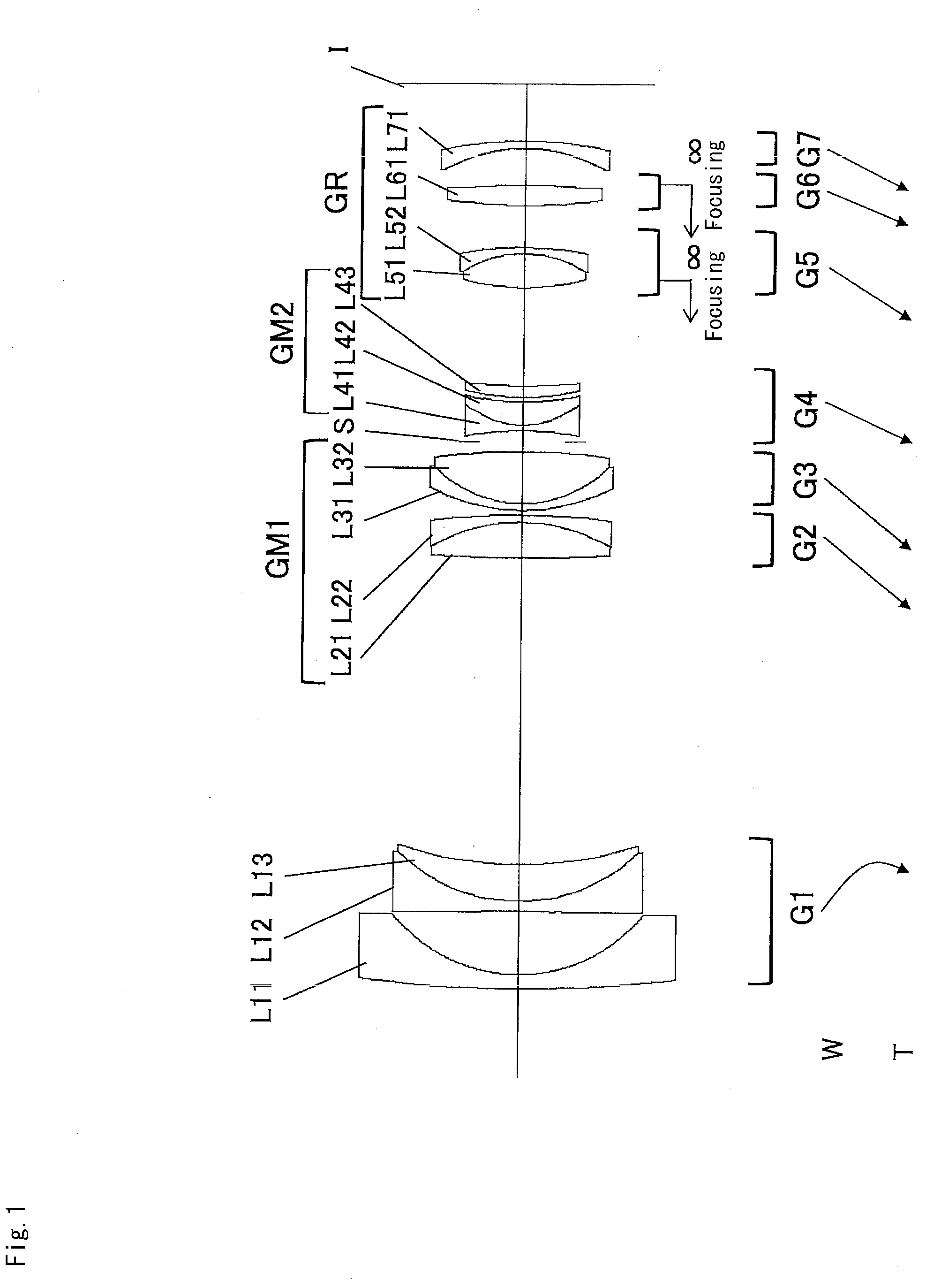
[0096] FIG. 1 is a sectional view of a variable magnification optical system according to a First Example. Meanwhile, in FIG. 1 and FIG. 4, FIG. 7, FIG. 10, FIG. 13, FIG. 16, FIG. 19 and FIG. 22 described later, arrows show movement trajectories of the respective lens groups upon varying magnification from a wide angle end state (W) to a telephoto end state (T).
[0097] The variable magnification optical system according to the present Example is composed of, in order from an object side, a first lens group G1 having negative refractive power, a first intermediate lens group GM1 having positive refractive power, an aperture stop S, a second intermediate lens group GM2 having negative refractive power, and a rear lens group GR having positive refractive power.
[0098] The first intermediate lens group GM1 is composed of, in order from the object side, a second lens group G2 having positive refractive power and a third lens group G3 having positive refractive power.
[0099] The second intermediate lens group GM2 is composed of a fourth lens group G4.
[0100] The rear lens group GR is composed of, in order from the object side, a fifth lens group G5 having positive refractive power, a sixth lens group G6 having positive refractive power, and a seventh lens group G7 having negative refractive power.
[0101] The first lens group G1 consists of, in order from the object side, a negative meniscus lens L11 having a convex surface facing the object side, and a cemented negative lens constructed by a double concave negative lens L12 cemented with a positive meniscus lens L13 having a convex surface facing the object side.
[0102] The second lens group G2 consists of a cemented positive lens constructed by a double convex positive lens L21 cemented with a negative meniscus lens L22 having a concave surface facing the object side.
[0103] The third lens group G3 consists of a cemented positive lens constructed by a negative meniscus lens L31 having a convex surface facing the object side cemented with a double convex positive lens L32.
[0104] The fourth lens group G4 consists of, in order from the object side, a cemented negative lens constructed by a double concave negative lens L41 cemented with a positive meniscus lens L42 having a convex surface facing the object side, and a positive meniscus lens L43 having a convex surface facing the object side.
[0105] The fifth lens group G5 consists of a cemented positive lens constructed by a double convex positive lens L51 cemented with a negative meniscus lens L52 having a concave surface facing the object side.
[0106] The sixth lens group G6 consists of a double convex positive lens L61.
[0107] The seventh lens group G7 consists of a negative meniscus lens L71 having a concave surface facing the object side.
[0108] In the variable magnification optical system according to the present Example, upon varying magnification between the wide angle end state and the telephoto end state, all lens groups of the first lens group G1 to the seventh lens group G7 are moved along the optical axis such that a distance between the first lens group G1 and the second lens group G2, a distance between the second lens group G2 and the third lens group G3, a distance between the third lens group G3 and the fourth lens group G4, a distance between the fourth lens group G4 and the fifth lens group G5, a distance between the fifth lens group G5 and the sixth lens group G6 and a distance between the sixth lens group G6 and the seventh lens group G7, are varied.
[0109] In the variable magnification optical system according to the present Example, focusing from an infinite distance object to a close distance object is carried out by moving the fifth lens group G5 and the sixth lens group G6 independently from each other as respective focusing lens groups.
[0110] Table 1 below shows various values of the variable magnification optical system relating to the present Example.
[0111] In Table 1, "f" denotes a focal length, and "BF" denotes a back focus, that is, a distance along the optical axis from the most image side lens surface to the image plane I.
[0112] In [Surface Data], "m" denotes an order of an optical surface counted from the object side, "r" denotes a radius of curvature, "d" denotes a surface-to-surface distance, that is, an interval from an n-th surface to an (n+1)-th surface, where n is an integer, "nd" denotes refractive index for d-line (wavelength .lamda.=587.6 nm) and ".nu.d" denotes an Abbe number for d-line (wavelength .lamda.=587 0.6 nm). Further, "OP" denotes an object surface, "Variable" denotes a variable surface-to-surface distance, "S" denotes an aperture stop, and "I" denotes an image plane. Meanwhile, radius of curvature r=.infin. denotes a plane surface, and refractive index of the air nd=1.00000 is omitted. In addition, a position of an aspherical surface is expressed by attaching "*" to the surface number, and in the column of the radius of curvature "r", a paraxial radius of curvature is shown.
[0113] In [Aspherical Data], with respect to an aspherical surface shown in [Surface Data], an aspherical surface coefficient and a conical coefficient are shown in the case where the aspherical surface is exhibited by the following expression:
x=(h.sup.2/r)/[1+{1-K(h/r).sup.2}.sup.1/2]+A4h.sup.4+A6h.sup.6+A8h.sup.8- +A10h.sup.10
where "h" denotes a height in the direction perpendicular to the optical axis, "x" denotes a sag amount that is a distance along the optical axis from the tangent surface at the vertex of each aspherical surface at the height "h"; "K" denotes a conical coefficient; "A4", "A6", "A8" and "A10" denote respective aspherical coefficients, and "r" denotes a paraxial radius of curvature that is a radius of curvature of a reference sphere. "E-n", where n is an integer, denotes ".times.10.sup.-n", for example, "1.234E-05" denotes "1.234.times.10.sup.-5". Second order aspherical coefficient "A2" is 0 and omitted.
[0114] In [Various Data], "FNO" denotes an F-number, "2w" denotes an angle of view (unit ".degree."), "Ymax" denotes a maximum image height, and "TL" denotes a total length of the variable magnification optical system according to the present Example, that is, a distance along the optical axis from the first lens surface to the image plane I, and "dn" denotes a variable distance from the n-th surface to the (n+1)-th surface. Meanwhile, "W" denotes a wide angle end state, "M" denotes an intermediate focal length state, "T" denotes a tele photo end state, "INF" denotes time upon focusing on an infinite distance object, and "CLO" denotes time upon focusing on a close distance object.
[0115] In [Lens Group Data], a starting surface ST and a focal length f of each lens group are shown.
[0116] In [Values for Conditional Expressions], values corresponding to respective conditional expressions of the variable magnification optical system according to the present Example, are shown.
[0117] It is noted, here, that "mm" is generally used for the unit of length such as the focal length f, the radius of curvature r and the unit for other lengths shown in Table 1. However, since similar optical performance can be obtained by an optical system proportionally enlarged or reduced, the unit is not necessarily to be limited to "mm".
[0118] Meanwhile, the explanation of reference symbols in Table 1 described above, is the same in Tables for the other Examples described herein later.
TABLE-US-00001 TABLE 1 First Example [Surface Data] m r d nd .nu.d OP .infin. 1 270.0000 2.900 1.74389 49.53 *2 33.2562 13.215 3 -1900.2102 2.100 1.59349 67.00 4 35.8236 7.700 2.00100 29.12 5 79.6938 Variable 6 271.3181 7.400 1.83481 42.73 7 -36.9149 1.500 1.75520 27.57 8 -164.0000 Variable 9 39.7511 1.500 1.85000 27.03 10 25.6246 10.800 1.59319 67.90 11 -134.6401 Variable 12 (S) .infin. 2.350 13 -65.9523 1.300 1.80100 34.92 14 18.5797 4.700 1.90366 31.27 15 51.6074 0.919 16 45.9293 2.500 1.94595 17.98 17 120.0000 Variable 18 47.5350 7.100 1.48749 70.31 19 -24.2409 1.300 1.69895 30.13 20 -74.7188 Variable 21 113.0000 4.200 1.58913 61.15 *22 -108.0000 Variable *23 -30.5616 1.500 1.58913 61.15 24 -81.9388 BF I .infin. [Aspherical Data] m:2 .kappa. = 0.0000 .sub. A4 = 2.97162E-06 A6 = 1.62510E-09 A8 = 2.42658E-13 A10 = 4.56491E-16 A12 = 8.02650E-19 m:22 .kappa. = 1.0000 A4 = 8.43912E-06 A6 = 6.68890E-10 A8 = 1.69267E-11 A10 = -5.36609E-14 m:23 .kappa. = 1.0000 A4 = 8.13845E-06 A6 = -4.05875E-09 A8 = 1.66491E-11 A10 = -5.84964E-14 [Various Data] Variable magnification ratio 2.99 W M T f 22.7 50.0 67.9 FNO 2.92 2.92 2.92 2.omega. 91.10 45.68 33.64 Ymax 19.32 21.60 21.60 TL 188.45 157.95 163.95 BF 11.75 20.19 25.26 W M T W M T INF INF INF CLO CLO CLO d5 63.985 10.998 3.100 63.985 10.998 3.100 d8 1.000 1.763 1.000 1.000 1.763 1.000 d11 1.900 12.973 26.707 1.900 12.973 26.707 d17 20.431 12.752 12.052 20.013 11.839 10.654 d20 8.701 16.480 16.780 8.112 16.125 16.831 d22 7.699 9.815 6.069 8.705 11.084 7.415 [Lens Group Data] Group ST f 1 1 -46.132 2 6 102.733 3 9 64.434 4 12 -89.031 5 18 92.237 6 21 94.399 7 23 -83.639 [Values for Conditional Expressions] (1) .sub. f1/fM2 = 0.518 (2) .sub. BFw/fw = 0.518 (3) .sub. |fF|/ft = 1.358 (4) .sub. f1N/f1 = 1.111 (5) .sub. D1Mw/fw = 2.819 (6) .nu.M1P/.nu.M1N = 2.463 (7) .sub. fM1P/fM1N = 0.587 (8) .omega.w = 45.55.degree.
[0119] FIGS. 2A, 2B and 2C are graphs showing various aberrations upon focusing on an infinite distance object, respectively, in the wide angle end state, in the intermediate focal length state and in the telephoto end state, of the variable magnification optical system according to the First Example.
[0120] FIGS. 3A, 3B and 3C are graphs showing various aberrations upon focusing on a close distance object, respectively, in the wide angle end state, in the intermediate focal length state and in the telephoto end state, of the variable magnification optical system according to the First Example.
[0121] In the graphs showing aberrations as drawn in FIG. 2 and FIG. 3, "FNO" denotes an F-number, "NA" denotes a numerical aperture, and "Y" denotes an image height. In graphs showing spherical aberration, the value of the numerical aperture or F-number corresponding to the maximum aperture is shown. In graphs showing astigmatism and distortion, the maximum value of the image height is shown. In graphs showing coma aberration, the value for each image height is shown. "d" denotes d-line (wavelength .lamda.=587.6 nm), and "g" denotes g-line (wavelength .lamda.=435.8 nm). In graphs showing astigmatism, a solid line indicates a sagittal image plane, and a broken line indicates a meridional image plane. Meanwhile, in graphs showing various aberrations in the other Examples as described below, the same symbols as in the present Example are employed.
[0122] As is apparent from the above-mentioned graphs showing various aberrations, the variable magnification optical system relating to the present Example can correct superbly various aberrations over the wide angle end state to the telephoto end state and has excellent imaging performance, and further has excellent imaging performance even upon focusing on a close distance object.
Second Example
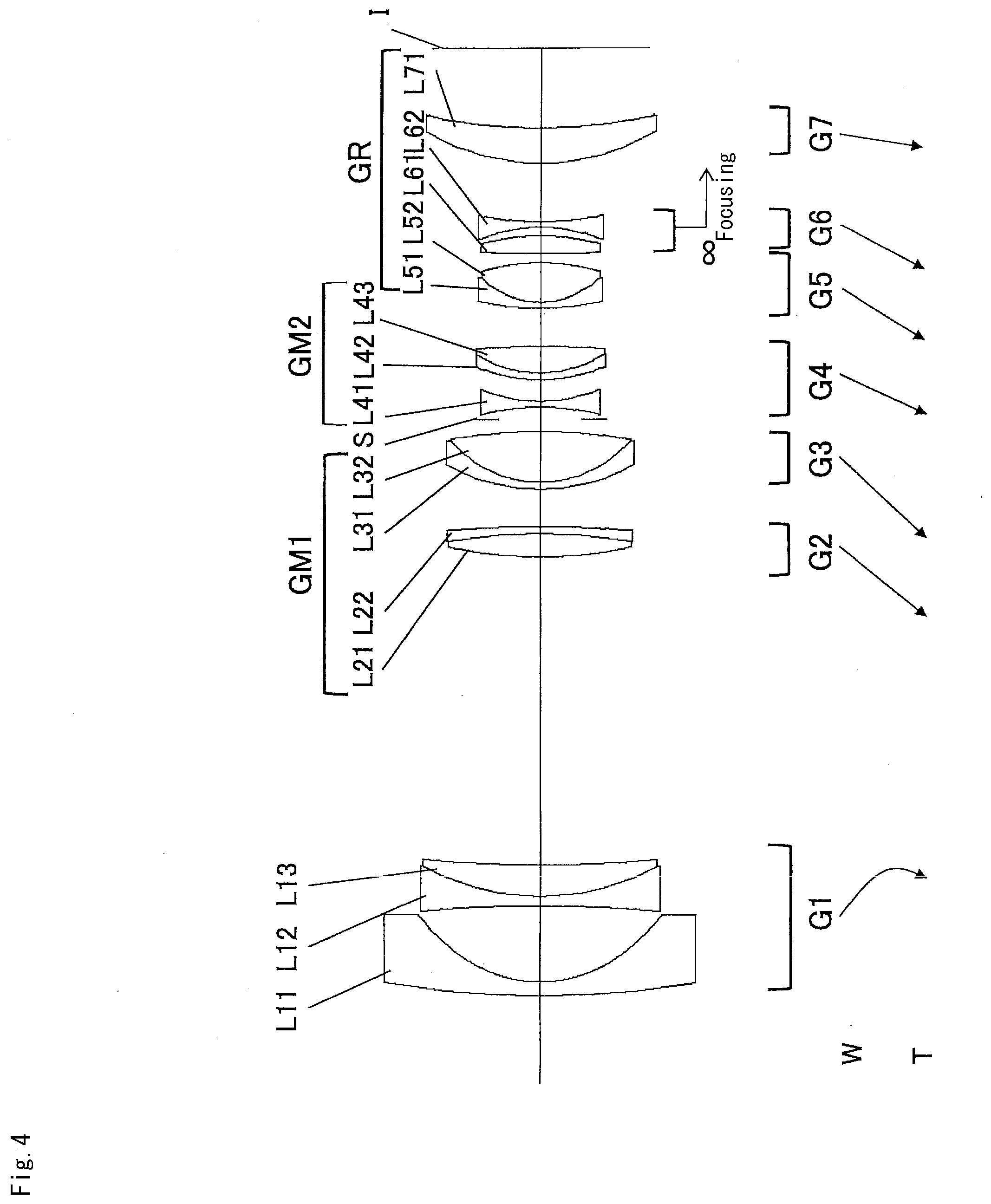
[0123] FIG. 4 is a sectional view of a variable magnification optical system according to a Second Example of the present application.
[0124] The variable magnification optical system according to the present Example is composed of, in order from an object side, a first lens group G1 having negative refractive power, a first intermediate lens group GM1 having positive refractive power, an aperture stop S, a second intermediate lens group GM2 having negative refractive power, and a rear lens group GR having positive refractive power.
[0125] The first intermediate lens group GM1 is composed of, in order from the object side, a second lens group G2 having positive refractive power and a third lens group G3 having positive refractive power.
[0126] The second intermediate lens group GM2 is composed of a fourth lens group G4.
[0127] The rear lens group GR is composed of, in order from the object side, a fifth lens group G5 having positive refractive power, a sixth lens group G6 having negative refractive power, and a seventh lens group G7 having positive refractive power.
[0128] The first lens group G1 consists of, in order from the object side, a negative meniscus lens L11 having a convex surface facing the object side, and a cemented positive lens constructed by a double concave negative lens L12 cemented with a positive meniscus lens L13 having a convex surface facing the object side.
[0129] The second lens group G2 consists of a cemented positive lens constructed by a double convex positive lens L21 cemented with a negative meniscus lens L22 having a concave surface facing the object side.
[0130] The third lens group G3 consists of a cemented positive lens constructed by a negative meniscus lens L31 having a convex surface facing the object side cemented with a double convex positive lens L32.
[0131] The fourth lens group G4 consists of, in order from the object side, a double concave negative lens L41 and a cemented positive lens constructed by a negative meniscus lens L42 having a convex surface facing the object side cemented with a double convex positive lens L43.
[0132] The fifth lens group G5 consists of a cemented positive lens constructed by a negative meniscus lens L51 having a convex surface facing the object side cemented with a double convex positive lens L52.
[0133] The sixth lens group G6 consists of, in order from the object side, a double convex positive lens L61 and a double concave negative lens L62.
[0134] The seventh lens group G7 consists of a positive meniscus lens L71 having a convex surface facing the object side.
[0135] In the variable magnification optical system according to the present Example, upon varying magnification between the wide angle end state and the telephoto end state, all lens groups of the first lens group G1 to the seventh lens group G7 are moved along the optical axis such that a distance between the first lens group G1 and the second lens group G2, a distance between the second lens group G2 and the third lens group G3, a distance between the third lens group G3 and the fourth lens group G4, a distance between the fourth lens group G4 and the fifth lens group G5, a distance between the fifth lens group G5 and the sixth lens group G6 and a distance between the sixth lens group G6 and the seventh lens group G7, are varied.
[0136] In the variable magnification optical system according to the present Example, focusing from an infinite distance object to a close distance object is carried out by moving the sixth lens group G6 toward the image plane as focusing lens group.
[0137] Table 2 below shows various values of the variable magnification optical system relating to the present Example.
TABLE-US-00002 TABLE 2 Second Example [Surface Data] m r d nd vd OP .infin. 1 199.9946 2.900 1.74389 49.53 *2 27.7434 15.922 *3 -285.3676 2.100 1.67798 54.89 4 50.5985 6.605 2.00100 29.14 5 262.0850 Variable 6 93.3673 4.795 1.83481 42.73 7 -123.3006 1.500 1.80518 25.45 8 -254.1381 Variable 9 40.5927 1.500 1.79504 28.69 10 25.0002 10.749 1.60300 65.44 11 -105.9135 Variable 12 (S) .infin. 2.540 13 -52.6667 1.300 1.85026 32.35 14 33.3539 4.586 15 37.2026 1.300 1.74950 35.25 16 25.3810 5.571 1.80809 22.74 17 -234.9670 Variable 18 62.4943 1.300 1.80518 25.45 19 18.1697 8.200 1.55332 71.68 *20 -42.1612 Variable *21 -6257.4714 3.600 1.80301 25.53 22 -49.3227 1.875 23 -33.3339 1.200 1.72825 28.38 24 70.6726 Variable 25 47.6911 7.458 1.90200 25.26 26 110.0504 BF I .infin. [Aspherical Data] m:2 .kappa. = 0.0000 .sub. A4 = 3.47464E-06 A6 = 2.06289E-09 A8 = -2.87066E-12 A10 = 6.84678E-15 A12 = -3.05130E-18 m:3 .kappa. = 1.0000 A4 = -3.34275E-07 A6 = -6.53686E-10 A8 = 1.41918E-12 A10 = -6.87012E-16 m:20 .kappa. = 1.0000 .sub. A4 = 3.21231E-06 A6 = -2.72101E-08 A8 = 1.74184E-10 A10 = -4.74606E-13 m:21 .kappa. = 1.0000 .sub. A4 = 4.04674E-06 A6 = -1.32981E-08 A8 = 1.27233E-10 A10 = -1.86784E-13 [Various Data] Variable magnification ratio 2.99 W M T f 22.7 50.0 67.9 FNO 2.92 2.92 2.92 2.omega. 90.12 47.98 35.62 Ymax 19.31 21.60 21.60 TL 199.49 166.47 170.49 BF 16.69 24.96 25.26 W M T W M T INF INF INF CLO CLO CLO d5 64.992 11.651 2.111 64.992 11.651 2.111 d8 7.938 1.000 1.000 7.938 1.000 1.000 d11 2.500 9.805 17.785 2.500 9.805 17.785 d17 8.103 6.811 2.000 8.103 6.811 2.000 d20 2.000 4.908 2.763 2.924 6.260 4.220 d24 12.267 22.329 34.572 11.343 20.977 33.114 [Lens Group Data] Group ST f 1 1 -43.850 2 6 81.660 3 9 58.238 4 12 -95.001 5 18 81.887 6 21 -66.376 7 25 88.300 [Values for Conditional Expressions] (1) .sub. f1/fM2 = 0.462 (2) .sub. BFw/fw = 0.735 (3) .sub. |fF|/ft = 0.978 (4) .sub. f1N/f1 = 0.995 (5) .sub. D1Mw/fw = 2.863 (6) .nu.M1P/.nu.M1N = 2.281 (7) .sub. fM1P/fM1N = 0.405 (8) .omega.w = 45.56
[0138] FIG. 5A, FIG. 5B and FIG. 5C are graphs showing various aberrations upon focusing on an infinite distance object, respectively, in the wide angle end state, in the intermediate focal length state and in the telephoto end state, of the variable magnification optical system according to the Second Example.
[0139] FIG. 6A, FIG. 6B and FIG. 6C are graphs showing various aberrations upon focusing on a close distance object, respectively, in the wide angle end state, in the intermediate focal length state and in the telephoto end state, of the variable magnification optical system according to the Second Example.
[0140] As is apparent from the above-mentioned graphs showing various aberrations, the variable magnification optical system relating to the present Example can correct superbly various aberrations over the wide angle end state to the telephoto end state and has excellent imaging performance, and further has excellent imaging performance even upon focusing on a close distance object.
Third Example
[0141] FIG. 7 is a sectional view of a variable magnification optical system according to a Third Example of the present application.
[0142] The variable magnification optical system according to the present Example is composed of, in order from an object side, a first lens group G1 having negative refractive power, a first intermediate lens group GM1 having positive refractive power, an aperture stop S, a second intermediate lens group GM2 having negative refractive power, and a rear lens group GR having positive refractive power.
[0143] The first intermediate lens group GM1 is composed of, in order from the object side, a second lens group G2 having positive refractive power and a third lens group G3 having positive refractive power.
[0144] The second intermediate lens group GM2 is composed of a fourth lens group G4.
[0145] The rear lens group GR is composed of, in order from the object side, a fifth lens group G5 having positive refractive power, a sixth lens group G6 having positive refractive power, and a seventh lens group G7 having negative refractive power.
[0146] The first lens group G1 consists of, in order from the object side, a negative meniscus lens L11 having a convex surface facing the object side, and a cemented negative lens constructed by a double concave negative lens L12 cemented with a positive meniscus lens L13 having a convex surface facing the object side.
[0147] The second lens group G2 consists of a cemented positive lens constructed by a double convex positive lens L21 cemented with a negative meniscus lens L22 having a concave surface facing the object side.
[0148] The third lens group G3 consists of a cemented positive lens constructed by a negative meniscus lens L31 having a convex surface facing the object side cemented with a double convex positive lens L32.
[0149] The fourth lens group G4 consists of, in order from the object side, a double concave negative lens L41 and a cemented negative lens constructed by a double concave negative lens L42 cemented with a double convex positive lens L43.
[0150] The fifth lens group G5 consists of a cemented positive lens constructed by a negative meniscus lens L51 having a convex surface facing the object side cemented with a double convex positive lens L52.
[0151] The sixth lens group G6 consists of a double convex positive lens L61.
[0152] The seventh lens group G7 is composed of, in order from the object side, a positive meniscus lens L71 having a concave surface facing the object side and a double concave negative lens L72.
[0153] In the variable magnification optical system according to the present Example, upon varying magnification between the wide angle end state and the telephoto end state, all lens groups of the first lens group G1 to the seventh lens group G7 are moved along the optical axis such that a distance between the first lens group G1 and the second lens group G2, a distance between the second lens group G2 and the third lens group G3, a distance between the third lens group G3 and the fourth lens group G4, a distance between the fourth lens group G4 and the fifth lens group G5, a distance between the fifth lens group G5 and the sixth lens group G6 and a distance between the sixth lens group G6 and the seventh lens group G7, are varied.
[0154] In the variable magnification optical system according to the present Example, focusing from an infinite distance object to a close distance object is carried out by moving the sixth lens group G6 along the optical axis toward the object as focusing lens group.
[0155] Table 3 below shows various values of the variable magnification optical system relating to the present Example.
TABLE-US-00003 TABLE 3 Third Example [Surface Data] m r d nd .nu.d OP .infin. 1 200.0000 2.900 1.74389 49.53 *2 29.9416 15.494 *3 -200.8674 2.100 1.69343 53.30 4 44.6733 7.746 1.85000 27.03 5 318.4789 Variable 6 108.1956 5.825 1.80400 46.60 7 -62.4397 1.500 1.84666 23.80 8 -135.1571 Variable 9 39.6194 1.500 1.84666 23.80 10 27.1969 9.538 1.60300 65.44 11 -223.7185 Variable 12 (S) .infin. 2.115 13 -77.7324 1.300 1.83481 42.73 14 186.4173 1.924 15 -51.8167 1.300 1.80100 34.92 16 27.4630 5.440 1.80809 22.74 17 -78.0293 Variable 18 273.2433 1.500 1.95000 29.37 19 29.6710 6.516 1.59319 67.90 20 -41.4738 Variable 21 39.0977 6.500 1.48749 70.31 22 -208.2456 Variable *23 -736.4795 8.500 1.55332 71.67 24 -42.9142 6.153 25 -34.6367 1.500 1.67798 54.89 *26 147.0962 BF I .infin. [Aspherical Data] m:2 K = 0.0000 A4 = 2.64488E-06 A6 = 7.93387E-10 A8 = -2.18796E-13 A10 = 2.18394E-15 A12 = -6.34900E-19 m:3 K = 1.0000 A4 = -2.63676E-07 A6 = -4.45738E-10 A8 = 9.61010E-13 A10 = -3.72624E-16 m:23 K = 1.0000 A4 = -2.62769E-07 A6 = 7.24281E-10 A8 = -9.63646E-13 A10 = -6.01683E-15 m:26 K = 1.0000 A4 = 5.86678E-07 A6 = 1.11104E-09 A8 = 1.08716E-11 A10 = -2.05060E-14 [Various Data] Variable magnification ratio 2.99 W M T f 22.7 50.0 67.9 FNO 2.92 2.92 2.92 2.omega. 90.26 47.38 35.28 Ymax 19.64 21.60 21.60 TL 204.49 174.12 175.49 BF 16.69 28.18 36.33 W M T W M T INF INF INF CLO CLO CLO d5 59.091 10.830 2.000 59.091 10.830 2.000 d8 13.328 1.000 1.000 13.328 1.000 1.000 d11 2.500 14.191 22.877 2.500 14.191 22.877 d17 9.032 7.248 2.000 9.032 7.248 2.000 d20 12.353 19.355 19.924 11.550 18.113 18.492 d22 2.147 3.969 2.006 2.949 5.211 3.438 [Lens Group Data] Group ST f 1 1 -40.605 2 6 77.859 3 9 66.608 4 12 -52.441 5 18 160.100 6 21 68.111 7 23 -97.113 [Values for Conditional Expressions] (1) f1/fM2 = 0.774 (2) BFw/fw = 0.735 (3) |fF|/ft = 1.003 (4) f1N/f1 = 1.174 (5) D1Mw/fw = 2.603 (6) .nu.M1P/.nu.M1N = 2.750 (7) fM1P/fM1N =0.376 (8) cow = 45.13.degree.
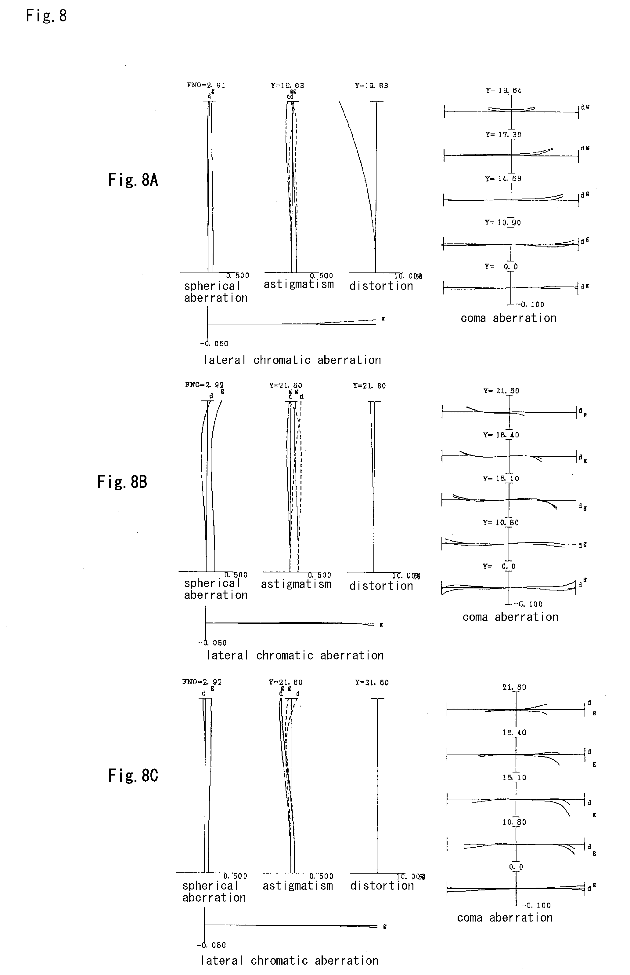
[0156] FIG. 8A, FIG. 8B and FIG. 8C are graphs showing various aberrations upon focusing on an infinite distance object, respectively, in the wide angle end state, in the intermediate focal length state and in the telephoto end state, of the variable magnification optical system according to the Third Example.
[0157] FIGS. 9A, 9B and 9C are graphs showing various aberrations upon focusing on a close distance object, respectively, in the wide angle end state, in the intermediate focal length state and in the telephoto end state, of the variable magnification optical system according to the Third Example.
[0158] As is apparent from the above-mentioned graphs showing various aberrations, the variable magnification optical system relating to the present Example can correct superbly various aberrations over the wide angle end state to the telephoto end state and has excellent imaging performance, and further has excellent imaging performance even upon focusing on a close distance object.
Fourth Example
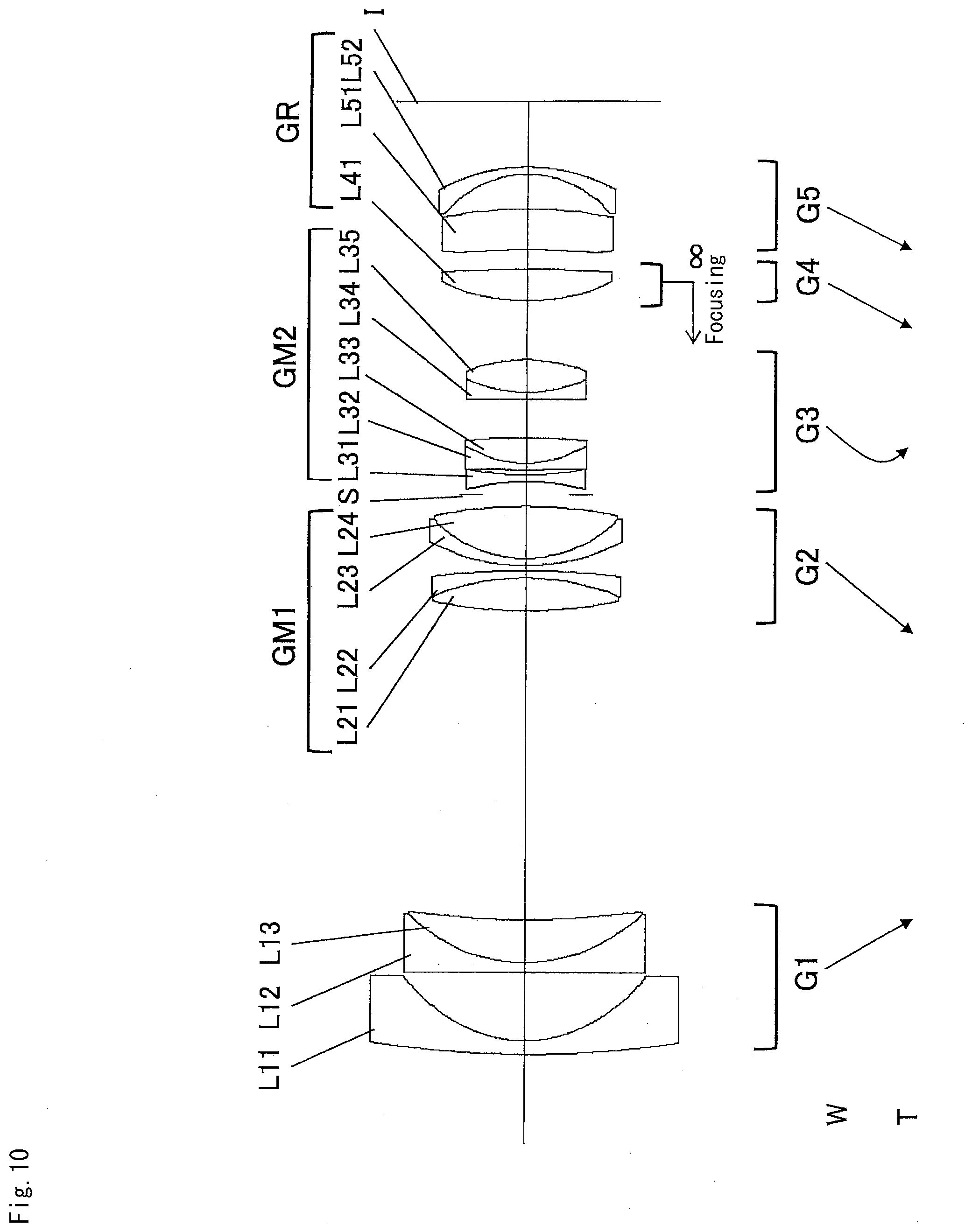
[0159] FIG. 10 is a sectional view of a variable magnification optical system according to a Fourth Example of the present application.
[0160] The variable magnification optical system according to the present Example is composed of, in order from an object side, a first lens group G1 having negative refractive power, a first intermediate lens group GM1 having positive refractive power, an aperture stop S, a second intermediate lens group GM2 having negative refractive power, and a rear lens group GR having positive refractive power.
[0161] The first intermediate lens group GM1 is composed of a second lens group G2 having positive refractive power.
[0162] The second intermediate lens group GM2 is composed of a third lens group G3.
[0163] The rear lens group GR is composed of, in order from the object side, a fourth lens group G4 having positive refractive power and a fifth lens group G5 having negative refractive power.
[0164] The first lens group G1 consists of, in order from the object side, a negative meniscus lens L11 having a convex surface facing the object side, and a cemented positive lens constructed by a negative meniscus lens L12 having a convex surface facing the object side cemented with a positive meniscus lens L13 having a convex surface facing the object side.
[0165] The second lens group G2 consists of, in order from the object side, a cemented positive lens constructed by a double convex positive lens L21 cemented with a negative meniscus lens L22 having a concave surface facing the object side, and a cemented positive lens constructed by a negative meniscus lens L23 having a convex surface facing the object side cemented with a double convex positive lens L24.
[0166] The third lens group G3 consists of, in order from the object side, a double concave negative lens L31, a cemented positive lens constructed by a negative meniscus lens L32 having a convex surface facing the object side cemented with a double convex positive lens L33, and a cemented positive lens constructed by a negative meniscus lens L34 having a convex surface facing the object side cemented with a double convex positive lens L35.
[0167] The fourth lens group G4 consists of a double convex positive lens L41.
[0168] The fifth lens group G5 consists of, in order from the object side, a positive meniscus lens L51 having a concave surface facing the object side and a negative meniscus lens L52 having a concave surface facing the object side.
[0169] In the variable magnification optical system according to the present Example, upon varying magnification between the wide angle end state and the telephoto end state, all lens groups of the first lens group G1 to the fifth lens group G5 are moved along the optical axis such that a distance between the first lens group G1 and the second lens group G2, a distance between the second lens group G2 and the third lens group G3, a distance between the third lens group G3 and the fourth lens group G4, and a distance between the fourth lens group G4 and the fifth lens group G5, are varied.
[0170] In the variable magnification optical system according to the present Example, focusing from an infinite distance object to a close distance object is carried out by moving the fourth lens group G4 toward the object as a focusing lens group.
[0171] Table 4 below shows various values of the variable magnification optical system relating to the present Example.
TABLE-US-00004 TABLE 4 Fourth Example [Surface Data] m r d nd .nu.d OP .infin. 1 200.0000 2.900 1.74389 49.53 *2 27.7802 14.448 *3 1296.6773 2.100 1.69343 53.30 4 34.8575 9.043 1.85000 27.03 5 174.0595 Variable 6 96.7860 6.874 1.80400 46.60 7 -52.4305 1.500 1.84666 23.80 8 -177.3376 1.000 9 43.5282 1.500 1.84666 23.80 10 26.9388 11.032 1.59319 67.90 11 -99.1173 Variable 12 (S) .infin. 2.808 13 -44.3650 1.300 1.80400 46.60 14 71.1308 1.016 15 416.3908 1.300 1.71999 50.27 16 23.6979 5.430 1.80809 22.74 17 -136.8595 7.916 18 2542.1309 1.500 1.90200 25.26 19 30.4377 6.844 1.59319 67.90 20 -35.3418 Variable 21 43.9437 6.500 1.48749 70.32 22 -380.1806 Variable *23 -107.1075 8.500 1.55332 71.68 24 -86.8745 7.112 25 -22.8630 1.500 1.67798 54.89 *26 -40.7153 BF I .infin. [Aspherical Data] m:2 K = 0.0000 A4 = 3.03915E-06 A6 = 2.46295E-09 A8 = -2.53532E-12 A10 = 3.74583E-15 A12 = -6.34900E-19 m:3 K = 1.0000 A4 = -2.78528E-07 A6 = -3.14446E-10 A8 = 3.58529E-13 A10 = -1.27209E-16 m:23 K = 1.0000 A4 = 6.52833E-06 A6 = 1.33655E-08 A8 = -7.01957E-12 A10 = 5.45626E-14 m:26 K = 1.0000 A4 = -2.26773E-06 A6 = -1.49552E-09 A8 = 2.69475E-11 A10 = -3.21917E-14 [Various Data] Variable magnification ratio 2.99 W M T f 22.7 50.0 67.9 FNO 2.92 2.92 2.92 2.omega. 90.80 48.02 35.28 Ymax 19.27 21.60 21.60 TL 199.61 181.30 175.49 BF 13.71 19.42 30.99 W M T W M T INF INF INF CLO CLO CLO d5 64.761 16.002 3.958 64.761 16.002 3.958 d11 2.500 10.994 21.579 2.500 10.994 21.579 d20 12.355 28.806 14.836 11.534 27.309 13.300 d22 4.172 3.955 2.000 4.993 5.453 3.536 [Lens Group Data] Group ST f 1 1 -43.293 2 6 37.710 3 12 -166.903 4 21 81.211 5 23 -87.491 [Values for Conditional Expressions] (1) f1/fM2 = 0.259 (2) BFw/fw = 0.604 (3) |fF|/ft = 1.196 (4) f1N/f1 = 1.009 (5) D1Mw/fw = 2.853 (6) .nu.M1P/.nu.M1N = 2.853 (7) fM1P/fM1N = 0.424 (8) .omega.w = 45.40.degree.
[0172] FIG. 11A, FIG. 11B and FIG. 11C are graphs showing various aberrations upon focusing on an infinite distance object, respectively, in the wide angle end state, in the intermediate focal length state and in the telephoto end state, of the variable magnification optical system according to the Fourth Example.
[0173] FIG. 12A, FIG. 12B and FIG. 12C are graphs showing various aberrations upon focusing on a close distance object, respectively, in the wide angle end state, in the intermediate focal length state and in the telephoto end state, of the variable magnification optical system according to the Fourth Example.
[0174] As is apparent from the above-mentioned graphs showing various aberrations, the variable magnification optical system relating to the present Example can correct superbly various aberrations over the wide angle end state to the telephoto end state and has excellent imaging performance, and further has excellent imaging performance even upon focusing on a close distance object.
Fifth Example
[0175] FIG. 13 is a sectional view of a variable magnification optical system according to a Fifth Example of the present application.
[0176] The variable magnification optical system according to the present Example is composed of, in order from an object side, a first lens group G1 having negative refractive power, a first intermediate lens group GM1 having positive refractive power, an aperture stop S, a second intermediate lens group GM2 having negative refractive power, and a rear lens group GR having positive refractive power.
[0177] The first intermediate lens group GM1 is composed of a second lens group G2 having positive refractive power.
[0178] The second intermediate lens group GM2 is composed of a third lens group G3.
[0179] The rear lens group GR is composed of, in order from the object side, a fourth lens group G4 having positive refractive power, a fifth lens group G5 having positive refractive power and a sixth lens group G6 having negative refractive power.
[0180] The first lens group G1 consists of, in order from the object side, a negative meniscus lens L11 having a convex surface facing the object side, and a cemented negative lens constructed by a negative meniscus lens L12 having a convex surface facing the object side cemented with a positive meniscus lens L13 having a convex surface facing the object side.
[0181] The second lens group G2 consists of, in order from the object side, a cemented positive lens constructed by a double convex positive lens L21 cemented with a negative meniscus lens L22 having a concave surface facing the object side, and a cemented positive lens constructed by a negative meniscus lens L23 having a convex surface facing the object side cemented with a double convex positive lens L24.
[0182] The third lens group G3 consists of, in order from the object side, a double concave negative lens L31, and a cemented positive lens constructed by a double concave negative lens L32 cemented with a double convex positive lens L33.
[0183] The fourth lens group G4 consists of a cemented positive lens constructed by a double convex positive lens L41 cemented with a negative meniscus lens L42 having a concave surface facing the object side.
[0184] The fifth lens group G5 consists of a double convex positive lens L51.
[0185] The sixth lens group G6 consists of a negative meniscus lens L61 having a concave surface facing the object side.
[0186] In the variable magnification optical system according to the present Example, upon varying magnification between the wide angle end state and the telephoto end state, all lens groups of the first lens group G1 to the sixth lens group G6 are moved along the optical axis such that a distance between the first lens group G1 and the second lens group G2, a distance between the second lens group G2 and the third lens group G3, a distance between the third lens group G3 and the fourth lens group G4, a distance between the fourth lens group G4 and the fifth lens group G5, and a distance between the fifth lens group G5 and the sixth lens group G6, are varied.
[0187] In the variable magnification optical system according to the present Example, focusing from an infinite distance object to a close distance object is carried out by moving the fourth lens group G4 and the fifth lens group G5 independently toward the object as respective focusing lens groups.
[0188] Table 5 below shows various values of the variable magnification optical system relating to the present Example.
TABLE-US-00005 TABLE 5 Fifth Example [Surface Data] m r d nd .nu.d OP .infin. 1 217.2239 2.900 1.74389 49.53 *2 30.2414 13.112 3 1223.5572 2.100 1.59349 67.00 4 35.8181 6.436 2.00069 25.46 5 72.5839 Variable 6 128.9112 7.447 1.81600 46.59 7 -39.6982 1.500 1.85000 27.03 8 -142.9408 1.000 9 40.8283 1.500 1.80518 25.45 10 25.0719 10.948 1.60300 65.44 11 -92.3055 Variable 12 (S) .infin. 2.486 13 -55.5201 1.300 1.90265 35.72 14 121.6217 1.190 15 -124.4061 1.300 1.67270 32.18 16 22.4038 6.400 1.80809 22.74 17 -97.2368 Variable 18 62.1388 6.900 1.48749 70.32 19 -23.2151 1.300 1.78472 25.64 20 -50.9732 Variable 21 186.2633 4.200 1.58913 61.15 *22 -79.5614 Variable *23 -33.8149 1.500 1.58913 61.15 24 -131.2649 BF I .infin. [Aspherical Surface Data] m:2 K = 0.0000 A4 = 3.46899E-06 A6 = 3.81982E-09 A8 = -6.40834E-12 A10 = 1.09738E-14 A12 = -4.82160E-18 m:22 K = 1.0000 A4 = 6.88818E-06 A6 = -6.09818E-10 A8 = 8.44660E-12 A10 = -2.63571E-14 m:23 K = 1.0000 A4 = 8.06346E-06 A6 = -8.60497E-09 A8 = 2.28581E-11 A10 = -5.12367E-14 [Various Data] Variable magnification ratio 2.99 W M T f 22.7 50.0 67.9 FNO 2.92 2.92 2.92 2.omega. 91.24 45.92 33.78 Ymax 19.34 21.60 21.60 TL 188.49 155.49 159.75 BF 16.19 19.69 24.21 W M T W M T INF INF INF CLO CLO CLO d5 63.857 10.035 2.501 63.857 10.035 2.501 d11 2.202 10.972 22.702 2.202 10.972 22.702 d17 19.524 10.852 10.688 19.122 9.959 9.322 d20 8.007 19.445 19.346 7.507 19.082 19.339 d22 5.193 10.974 6.787 6.095 12.231 8.161 [Lens Group Data] Group ST f 1 1 -42.007 2 6 36.073 3 12 -74.292 4 18 96.221 5 21 95.186 6 23 -77.759 [Values for Conditional Expressions] (1) f1/fM2 = 0.565 (2) BFw/fw = 0.713 (3) |fF|/ft = 1.402 (4) f1N/f1 = 1.132 (5) D1Mw/fw = 2.813 (6) .nu.M1P/.nu.M1N = 2.421 (7) fM1P/fM1N = 0.521 (8) .omega.w = 45.62.degree.
[0189] FIG. 14A, FIG. 14B and FIG. 14C are graphs showing various aberrations upon focusing on an infinite distance object, respectively, in the wide angle end state, in the intermediate focal length state and in the telephoto end state, of the variable magnification optical system according to the Fifth Example.
[0190] FIG. 15A, FIG. 15B and FIG. 15C are graphs showing various aberrations upon focusing on a close distance object, respectively, in the wide angle end state, in the intermediate focal length state and in the telephoto end state, of the variable magnification optical system according to the Fifth Example.
[0191] As is apparent from the above-mentioned graphs showing various aberrations, the variable magnification optical system relating to the present Example can correct superbly various aberrations over the wide angle end state to the telephoto end state and has excellent imaging performance, and further has excellent imaging performance even upon focusing on a close distance object.
Sixth Example
[0192] FIG. 16 is a sectional view of a variable magnification optical system according to a Sixth Example of the present application.
[0193] The variable magnification optical system according to the present Example is composed of, in order from an object side, a first lens group G1 having negative refractive power, a first intermediate lens group GM1 having positive refractive power, an aperture stop S, a second intermediate lens group GM2 having negative refractive power, and a rear lens group GR having positive refractive power.
[0194] The first intermediate lens group GM1 is composed of, in order from the object side, a second lens group G2 having positive refractive power and a third lens group G3 having positive refractive power.
[0195] The second intermediate lens group GM2 is composed of a fourth lens group G4.
[0196] The rear lens group GR is composed of, in order from the object side, a fifth lens group G5 having positive refractive power, a sixth lens group G6 having positive refractive power, and a seventh lens group G7 having negative refractive power.
[0197] The first lens group G1 consists of, in order from the object side, a negative meniscus lens L11 having a convex surface facing the object side, and a cemented negative lens constructed by a negative meniscus lens L12 having a convex surface facing the object side cemented with a positive meniscus lens L13 having a convex surface facing the object side.
[0198] The second lens group G2 consists of a cemented positive lens constructed by a double convex positive lens L21 cemented with a negative meniscus lens L22 having a concave surface facing the object.
[0199] The third lens group G3 consists of a cemented positive lens constructed by a negative meniscus lens L31 having a convex surface facing the object side cemented with a double convex positive lens L32.
[0200] The fourth lens group G4 consists of a cemented negative lens constructed by a double concave negative lens L41 cemented with a positive meniscus lens L42 having a convex surface facing the object side.
[0201] The fifth lens group G5 consists of a cemented positive lens constructed by a double convex positive lens L51 cemented with a negative meniscus lens L52 having a concave surface facing the object side.
[0202] The sixth lens group G6 consists of a double convex positive lens L61.
[0203] The seventh lens group G7 consists of a negative meniscus lens L71 having a concave surface facing the object side.
[0204] In the variable magnification optical system according to the present Example, upon varying magnification between the wide angle end state and the telephoto end state, all lens groups of the first lens group G1 to the seventh lens group G7 are moved along the optical axis such that a distance between the first lens group G1 and the second lens group G2, a distance between the second lens group G2 and the third lens group G3, a distance between the third lens group G3 and the fourth lens group G4, a distance between the fourth lens group G4 and the fifth lens group G5, a distance between the fifth lens group G5 and the sixth lens group G6 and a distance between the sixth lens group G6 and the seventh lens group G7, are varied.
[0205] In the variable magnification optical system according to the present Example, focusing from an infinite distance object to a close distance object is carried out by moving the fifth lens group G5 and the sixth lens group G6 along the optical axis independently toward the object as respective focusing lens groups.
[0206] Table 6 below shows various values of the variable magnification optical system relating to the present Example.
TABLE-US-00006 TABLE 6 Sixth Example [Surface Data] m r d nd .nu.d OP .infin. 1 259.2015 2.900 1.74389 49.53 *2 30.9799 13.410 3 1201.6909 2.100 1.59349 66.99 4 36.4155 6.936 2.00100 29.14 5 81.5436 Variable 6 124.3745 6.555 1.80400 46.60 7 -55.7538 1.500 1.72825 28.38 8 -633.0468 Variable 9 44.9659 1.500 1.85000 27.03 10 27.3358 10.990 1.59319 67.90 11 -89.5168 Variable 12 (S) .infin. 2.562 13 -58.2664 1.300 1.68893 31.16 14 20.8969 4.742 1.80809 22.74 15 201.5296 Variable 16 52.2605 6.900 1.48749 70.31 17 -26.1209 1.300 1.69895 30.13 18 -72.7540 Variable 19 130.0000 4.200 1.58913 61.15 *20 -100.4826 Variable *21 -44.3630 1.500 1.58913 61.15 22 -412.9422 BF I .infin. [Aspherical Surface Data] m:2 K = 0.0000 A4 = 3.40299E-06 A6 = 1.78453E-09 A8 = -2.01869E-13 A10 = 1.07948E-15 A12 = 2.74510E-19 m:20 K = 1.0000 A4 = 8.80591E-06 A6 = -1.07404E-09 A8 = 1.74456E-11 A10 = -2.66494E-14 m:21 K = 1.0000 A4 = 6.66893E-06 A6 = -5.20154E-09 A8 = 5.00802E-12 A10 = -7.75803E-15 [Various Data] Variable magnification ratio 2.99 W M T f 22.7 50.0 67.9 FNO 2.92 2.92 2.92 2.omega. 91.30 45.88 33.64 Ymax 19.36 21.60 21.60 TLL 188.49 156.49 165.34 BF 14.19 20.41 24.73 W M T W M T INF INF INF CLO CLO CLO d5 64.909 10.197 2.263 64.909 10.197 2.263 d8 1.000 1.000 1.000 1.000 1.000 1.000 d11 2.200 12.573 28.831 2.200 12.573 28.831 d15 22.896 13.304 11.893 22.388 12.281 10.318 d18 8.047 19.430 19.884 7.707 19.294 20.259 d20 6.853 11.181 8.344 7.701 12.340 9.543 [Lens Group Data] Group ST f 1 1 -45.334 2 6 112.275 3 9 63.547 4 12 -98.234 5 16 92.914 6 19 96.856 7 21 -84.494 [Values for Conditional Expressions] (1) f1/fM2 = 0.461 (2) BFw/fw = 0.625 (3) |fF|/ft = 1.368 (4) f1N/f1 = 1.049 (5) D1Mw/fw = 2.859 (6) .nu.M1P/.nu.M1N = 2.393 (7) fM1P/fM1N = 0.435 (8) .omega.w = 45.65.degree.
[0207] FIG. 17A, FIG. 17B and FIG. 17C are graphs showing various aberrations upon focusing on an infinite distance object, respectively, in the wide angle end state, in the intermediate focal length state and in the telephoto end state, of the variable magnification optical system according to the Sixth Example.
[0208] FIG. 18A, FIG. 18B and FIG. 18C are graphs showing various aberrations upon focusing on a close distance object, respectively, in the wide angle end state, in the intermediate focal length state and in the telephoto end state, of the variable magnification optical system according to the Sixth Example.
[0209] As is apparent from the above-mentioned graphs showing aberrations, the variable magnification optical system relating to the present Example can correct superbly various aberrations over the wide angle end state to the telephoto end state and has excellent imaging performance, and further has excellent imaging performance even upon focusing on a close distance object.
Seventh Example
[0210] FIG. 19 is a sectional view of a variable magnification optical system according to a Seventh Example of the present application.
[0211] The variable magnification optical system according to the present Example is composed of, in order from an object side, a first lens group G1 having negative refractive power, a first intermediate lens group GM1 having positive refractive power, an aperture stop S, a second intermediate lens group GM2 having negative refractive power, and a rear lens group GR having positive refractive power.
[0212] The first intermediate lens group GM1 is composed of a second lens group G2 having positive refractive power.
[0213] The second intermediate lens group GM2 is composed of a third lens group G3.
[0214] The rear lens group GR is composed of, in order from the object side, a fourth lens group G4 having positive refractive power, a fifth lens group G5 having positive refractive power and a sixth lens group G6 having negative refractive power.
[0215] The first lens group G1 consists of, in order from the object side, a negative meniscus lens L11 having a convex surface facing the object side, and a cemented negative lens constructed by a double concave negative lens L12 cemented with a positive meniscus lens L13 having a convex surface facing the object side.
[0216] The second lens group G2 consists of, in order from the object side, a cemented positive lens constructed by a double convex positive lens L21 cemented with a negative meniscus lens L22 having a concave surface facing the object side, and a cemented positive lens constructed by a negative meniscus lens L23 having a convex surface facing the object side cemented with a double convex positive lens L24.
[0217] The third lens group G3 consists of, in order from the object side, a double concave negative lens L31, a cemented positive lens constructed by a negative meniscus lens L32 having a convex surface facing the object side cemented with a double convex positive lens L33 and a cemented positive lens constructed by a double concave negative lens L33 cemented with a double convex positive lens L34.
[0218] The fourth lens group G4 consists of a double convex positive lens L41.
[0219] The fifth lens group G5 consists of a positive meniscus lens L51 having a concave surface facing the object side.
[0220] The sixth lens group G6 consists of a negative meniscus lens L61 having a concave surface facing the object side.
[0221] In the variable magnification optical system according to the present Example, upon varying magnification between the wide angle end state and the telephoto end state, all lens groups of the first lens group G1 to the sixth lens group G6 are moved along the optical axis such that a distance between the first lens group G1 and the second lens group G2, a distance between the second lens group G2 and the third lens group G3, a distance between the third lens group G3 and the fourth lens group G4, a distance between the fourth lens group G4 and the fifth lens group G5, and a distance between the fifth lens group G5 and the sixth lens group G6, are varied.
[0222] In the variable magnification optical system according to the present Example, focusing from an infinite distance object to a close distance object is carried out by moving the fourth lens group G4 along the optical axis toward the object as a focusing lens group.
[0223] Table 7 below shows various values of the variable magnification optical system relating to the present Example.
TABLE-US-00007 TABLE 7 Seventh Example [Surface Data] m r d nd .nu.d OP .infin. 1 200.0000 2.900 1.74389 49.53 *2 28.4969 14.488 *3 -5398.0521 2.100 1.69343 53.30 4 36.6732 8.665 1.85000 27.03 5 187.9030 Variable 6 91.7611 6.648 1.80400 46.60 7 -55.7166 1.500 1.84666 23.80 8 -203.7508 1.000 9 42.9517 1.500 1.84666 23.80 10 26.9325 10.417 1.59319 67.90 11 -98.1277 Variable 12 (S) .infin. 2.820 13 -45.5709 1.300 1.80400 46.60 14 57.2932 0.868 15 120.2007 1.300 1.71999 50.27 16 23.4150 5.485 1.80809 22.74 17 -181.7727 8.145 18 -482.8882 1.500 1.90200 25.26 19 32.5158 6.892 1.59319 67.90 20 -35.1691 Variable 21 47.0119 6.500 1.48749 70.32 22 -168.6086 Variable *23 -111.3712 8.500 1.55332 71.68 24 -71.1538 Variable 25 -29.2568 1.500 1.67798 54.89 *26 -86.3647 BF I .infin. [Aspherical Data] m:2 K = 0.0000 A4 = 3.18150E-06 A6 = 1.29143E-09 A8 = -4.45637E-13 A10 = 2.21668E-15 A12 = -6.34900E-19 m:3 K = 1.0000 A4 = -1.73423E-07 A6 = -4.20289E-10 A8 = 7.96941E-13 A10 = -4.23115E-16 m:23 K = 1.0000 A4 = 2.52053E-06 A6 = 5.96196E-09 A8 = 1.22687E-12 A10 = -9.60903E-15 m:26 K = 1.0000 A4 = -3.00816E-06 A6 = 2.06736E-09 A8 = 2.50057E-11 A10 = -4.88231E-14 [Various Data] Variable magnification ratio 2.99 W M T f 22.7 50.0 67.9 FNO 2.92 2.92 2.92 2.omega. 90.82 47.84 35.28 Ymax 19.42 21.60 21.60 TL 199.64 180.36 175.49 BF 14.74 19.85 28.18 W M T W M T INF INF INF CLO CLO CLO d5 65.865 14.675 2.075 65.865 14.675 2.075 d11 2.500 9.999 19.897 2.500 9.999 19.897 d20 12.261 28.219 17.697 11.472 26.839 16.195 d22 2.239 3.776 2.000 3.027 5.155 3.503 d24 8.010 9.814 11.610 8.010 9.814 11.610 [Lens Group Data] Group ST f 1 1 -43.315 2 6 37.392 3 12 -136.693 4 21 76.163 5 23 331.174 6 25 -65.961 [Values for Conditional Expressions] (1) f1/fM2 = 0.317 (2) BFw/fw = 0.649 (3) |fF|/ft = 1.122 (4) f1N/f1 = 1.039 (5) D1Mw/fw = 2.902 (6) .nu.M1P/.nu.M1N = 2.853 (7) fM1P/fM1N = 0.413 (8) .omega.w = 45.41.degree.
[0224] FIG. 20A, FIG. 20B and FIG. 20C are graphs showing various aberrations upon focusing on an infinite distance object, respectively, in the wide angle end state, in the intermediate focal length state and in the telephoto end state, of the variable magnification optical system according to the Seventh Example.
[0225] FIG. 21A, FIG. 21B and FIG. 21C are graphs showing various aberrations upon focusing on a close distance object, respectively, in the wide angle end state, in the intermediate focal length state and in the telephoto end state, of the variable magnification optical system according to the Seventh Example.
[0226] As is apparent from the above-mentioned graphs showing various aberrations, the variable magnification optical system relating to the present Example can correct superbly various aberrations over the wide angle end state to the telephoto end state and has excellent imaging performance, and further has excellent imaging performance even upon focusing on a close distance object.
Eighth Example
[0227] FIG. 22 is a sectional view of a variable magnification optical system according to an Eighth Example of the present application.
[0228] The variable magnification optical system according to the present Example is composed of, in order from an object side, a first lens group G1 having negative refractive power, a first intermediate lens group GM1 having positive refractive power, an aperture stop S, a second intermediate lens group GM2 having negative refractive power, and a rear lens group GR having positive refractive power.
[0229] The first intermediate lens group GM1 is composed of a second lens group G2 having positive refractive power.
[0230] The second intermediate lens group GM2 is composed of a third lens group G3.
[0231] The rear lens group GR is composed of, in order from the object side, a fourth lens group G4 having positive refractive power, a fifth lens group G5 having negative refractive power, a sixth lens group G6 having positive refractive power and a seventh lens group G7 having negative refractive power.
[0232] The first lens group G1 consists of, in order from the object side, a negative meniscus lens L11 having a convex surface facing the object side, and a cemented positive lens constructed by a negative meniscus lens L12 having a convex surface facing the object side cemented with a positive meniscus lens L13 having a convex surface facing the object side.
[0233] The second lens group G2 consists of, in order from the object side, a cemented positive lens constructed by a double convex positive lens L21 cemented with a negative meniscus lens L22 having a concave surface facing the object side, and a cemented positive lens constructed by a negative meniscus lens L23 having a convex surface facing the object side cemented with a double convex positive lens L24.
[0234] The third lens group G3 consists of, in order from the object side, a negative meniscus lens L31 having a concave surface facing the object side, and a cemented positive lens constructed by a double concave negative lens L32 cemented with a positive meniscus lens L33 having a convex surface facing the object side.
[0235] The fourth lens group G4 consists of a double convex positive lens L41.
[0236] The fifth lens group G5 consists of a negative meniscus lens L51 having a concave surface facing the object side.
[0237] The sixth lens group G6 consists of a double convex positive lens L61.
[0238] The seventh lens group G7 consists of a negative meniscus lens L71 having a concave surface facing the object side.
[0239] In the variable magnification optical system according to the present Example, upon varying magnification between the wide angle end state and the telephoto end state, all lens groups of the first lens group G1 to the seventh lens group G7 are moved along the optical axis such that a distance between the first lens group G1 and the second lens group G2, a distance between the second lens group G2 and the third lens group G3, a distance between the third lens group G3 and the fourth lens group G4, a distance between the fourth lens group G4 and the fifth lens group G5, a distance between the fifth lens group G5 and the sixth lens group G6 and a distance between the sixth lens group G6 and the seventh lens group G7, are varied.
[0240] In the variable magnification optical system according to the present Example, focusing from an infinite distance object to a close distance object is carried out by moving the fourth lens group G4, the fifth lens group G5 and the sixth lens group G6 independently from each other along the optical axis toward the object as respective focusing lens groups.
[0241] Table 8 below shows various values of the variable magnification optical system relating to the present Example.
TABLE-US-00008 TABLE 8 Eighth Example [Surface Data] m r d nd .nu.d OP .infin. 1 250.0000 2.900 1.74389 49.53 *2 28.0269 12.424 3 154.1167 2.100 1.59349 67.00 4 32.5416 6.969 2.00069 25.46 5 61.8764 Variable 6 175.0869 5.997 1.81600 46.59 7 -52.8034 1.500 1.85000 27.03 8 -204.9882 1.000 9 45.2860 1.500 1.80518 25.45 10 26.6188 11.527 1.60300 65.44 11 -76.6492 Variable 12 (S) .infin. 2.465 13 -64.5009 1.300 1.90265 35.72 14 -217.6883 0.200 15 -214.1041 1.300 1.67270 32.18 16 26.6878 6.400 1.80809 22.74 17 502.6822 Variable 18 65.6282 5.000 1.48749 70.32 19 -65.3105 Variable 20 -52.0851 1.300 1.84666 23.80 21 -201.9547 Variable 22 185.0000 5.300 1.58913 61.15 *23 -50.5905 Variable *24 -27.3977 1.500 1.58913 61.15 25 -49.4756 BF I .infin. [Aspherical Data] m:2 K = 0.0000 A4 = 3.95960E-06 A6 = 3.76748E-09 A8 =-5.23494E-12 A10 = 1.04782E-14 A12 =-4.82160E-18 m:23 K = 1.0000 A4 = 6.76320E-06 A6 = -8.33082E-09 A8 = 3.88079E-11 A10 = -7.09278E-14 m:24 K = 1.0000 A4 = 5.00393E-06 A6 = -8.92918E-09 A8 = 2.86537E-11 A10 = -5.32582E-14 [Various Data] Variable magnification ratio 2.99 W M T f 22.7 50.0 67.9 FNO 3.03 3.00 3.03 2.omega. 91.04 45.96 33.62 Ymax 19.30 21.60 21.60 TL 188.49 155.49 167.35 BF 16.20 23.37 32.67 W M T W M T INF INF INF CLO CLO CLO d5 64.883 10.266 5.946 64.883 10.266 5.946 d11 2.200 12.775 27.038 2.200 12.775 27.038 d17 20.035 8.462 6.571 19.026 7.439 4.593 d19 2.030 3.706 4.816 1.360 3.164 4.349 d21 4.601 9.046 14.467 4.908 8.936 15.092 d23 7.862 17.178 5.159 9.234 18.853 6.979 [Lens Group Data] Group ST f 1 1 -42.744 2 6 40.599 3 12 -105.371 4 18 68.000 5 20 -83.229 6 22 68.000 7 24 -106.909 [Values for Conditional Expressions] (1) f1/fM2 = 0.406 (2) BFw/fw = 0.713 (3) |fF|/ft = 1.001 (4) f1N/f1 = 0.998 (5) D1Mw/fw = 2.858 (6) .nu.M1P/.nu.M1N = 2.421 (7) fM1P/fM1N = 0.456 (8) .omega.w = 45.52.degree.
[0242] FIG. 23A, FIG. 23B and FIG. 23C are graphs showing various aberrations upon focusing on an infinite distance object, respectively, in the wide angle end state, in the intermediate focal length state and in the telephoto end state, of the variable magnification optical system according to the Eighth Example.
[0243] FIG. 24A, FIG. 24B and FIG. 24C are graphs showing various aberrations upon focusing on a close distance object, respectively, in the wide angle end state, in the intermediate focal length state and in the telephoto end state, of the variable magnification optical system according to the Eighth Example.
[0244] As is apparent from the above-mentioned graphs showing various aberrations, the variable magnification optical system relating to the present Example can correct superbly various aberrations over the wide angle end state to the telephoto end state and has excellent imaging performance, and further has excellent imaging performance even upon focusing on a close distance object.
[0245] According to each of the above described Examples, it is possible to realize a variable magnification optical system that has focusing lens group (s) which is (are) light in weight and downsized and which can suppress superbly variations in aberrations upon varying magnification from a wide angle end state to a telephoto end state and variations in aberrations upon carrying out focusing from an infinite distance object to a close distance object. In this variable magnification optical system, since the focusing lens group(s) is(are) made small in size and light in weight, driving mechanism for the focusing lens group(s) is(are) also downsized, so it is possible to realize high speed as well as noiseless focusing operation without making lens barrel large.
[0246] Meanwhile, it is noted that each of the above described Examples is a concrete example of the invention of the present application, and the invention of the present application is not limited to them. The contents described below can be adopted appropriately without deteriorating optical performance of the variable magnification optical systems according to the present embodiment.
[0247] Although variable magnification optical systems having a five group configuration, a six group configuration, and a seven group configuration, were illustrated above as numerical examples of the variable magnification optical systems according to the present application, the invention of the present application is not limited to them and variable magnification optical systems having other configurations, such as eight group configuration or the like, can be configured. Concretely, a lens configuration that a lens or a lens group is added to the most object side or the most image side of the variable magnification optical system according to each of the above described Examples is possible. Alternatively, a lens or a lens group may be added between the first lens group G1 and the first intermediate lens group GM1. Alternatively, a lens or a lens group may be added between the first intermediate lens group GM1 and the second intermediate lens group GM2. Alternatively, a lens or a lens group may be added between the second intermediate lens group GM2 and the rear lens group GR.
[0248] Further, in each of the above described Examples, configurations that the first intermediate lens group GM1 is composed of the second lens group G2 or of the second lens group G2 and the third lens groups G3, were illustrated, but configurations are not limited to them. Further, in each of the above described Examples, configurations that the second intermediate lens group GM2 is composed of the third lens group G3, or of the fourth lens group G4, or of the third lens groups G3 and the fourth lens group G4, were illustrated, but configurations are not limited to them.
[0249] Further, in each of the above described Examples, one, two or three lens groups, are adopted as focusing lens groups, but a part in lens group, or four or more lens groups may be adopted for focusing lens group (s). Each of the focusing lens groups may be composed of one or two lens components, and a configuration composed of one lens component is more preferable. Auto focusing can be applied for such focusing group(s), and drive by motor for auto focusing, such as, ultrasonic motor, stepping motor, and VCM motor may be suitably adopted.
[0250] Further, in the variable magnification optical systems according to each of the above described Examples, any lens group in the entirety thereof or a portion thereof can be moved in a direction including a component perpendicular to the optical axis as a vibration reduction lens group, or rotationally moved (swayed) in an in-plane direction including the optical axis, whereby a configuration of a vibration reduction can be taken.
[0251] Further, in the variable magnification optical systems according to each of the above described Examples, a lens surface of a lens may be a spherical surface, a plane surface, or an aspherical surface. When a lens surface is a spherical surface or a plane surface, lens processing, assembling and adjustment become easy, and it is possible to prevent deterioration in optical performance caused by lens processing, assembling and adjustment errors, so that it is preferable. Moreover, even if an image plane is shifted, deterioration in depiction performance is little, so that it is preferable. When a lens surface is an aspherical surface, the aspherical surface may be fabricated by a grinding process, a glass molding process that a glass material is formed into an aspherical shape by a mold, or a compound type process that a resin material is formed into an aspherical shape on a glass lens surface. A lens surface may be a diffractive optical surface, and a lens may be a graded-index type lens (GRIN lens) or a plastic lens.
[0252] Further, in the variable magnification optical systems according to each of the above described Examples, it is preferable that the aperture stop S is disposed between the second lens group G2 and the third lens group G3, or between the third lens group G3 and the fourth lens group G4. But, the function may be substituted by a lens frame without disposing a member as an aperture stop.
[0253] Moreover, the lens surface(s) of the lenses configuring the variable magnification optical system according to each of the above described Examples, may be coated with anti-reflection coating(s) having a high transmittance in a wide wavelength region. With this contrivance, it is feasible to reduce a flare as well as ghost and attain excellent optical performance with high contrast.
[0254] Next, a camera equipped with the variable magnification optical system according to the present embodiment, will be explained with referring to FIG. 25. FIG. 25 is a view showing a configuration of the camera equipped with the variable magnification optical system according to the present embodiment. The camera 1, as shown in FIG. 25, is a so-called mirror-less camera of a lens interchangeable type equipped with the variable magnification optical system according to the first Example as an imaging lens 2.
[0255] In the present camera 1, a light emitted from an unillustrated object (an object to be photo-taken) is converged by the imaging lens 2, through a unillustrated OLPF (Optical low pass filter), and forms an image of the object on an imaging plane of an imaging portion 3. The light from the object is photo-electrically converted through a photo-electric conversion element provided on the imaging portion 3 to form a picture image of the object. This picture image is displayed on an EVF (electric view finder) 4 provided on the camera 1. Accordingly, a photographer can observe the object to be photo-taken through the EVF.
[0256] Further, upon unillustrated release button being depressed by the photographer, the picture image of the object formed by the imaging portion 3 is stored in an unillustrated memory. Thus, the photographer can take a photo of the object by the camera 1.
[0257] It is noted here that the variable magnification optical system relating to the First Example mounted on the camera 1 as the imaging lens 2, has superb optical performance as described above and the focusing lens group(s) is (are) made light in weight and small in size. In other words, by making the focusing lens group (s) small in size and light in weight, high speed focusing can be realized, and it is possible to attain superb optical performances that variations in aberrations upon varying magnification from the wide angle end state to the telephoto end state as well as variations in aberrations upon carrying out focusing from an infinite distance object to a close distance object, can be suppressed.
[0258] Incidentally, even in a case where a camera in which the variable magnification optical system according to any of the before-mentioned Second to Eighth Examples is installed as the imaging lens 2, is configured, the camera also can the same effects as those of the above-mentioned camera 1. Further, even when the variable magnification optical system according to any of the Examples is installed in a camera of a single lens reflex type equipped with a quick return mirror in which the object image is observed through a finder optical system, the camera also can have the same effects as those of the above-mentioned camera 1.
[0259] Next, an outline of a method for manufacturing the variable magnification optical system according to the present embodiment, is described with referring to FIG. 26. FIG. 26 is a flowchart schematically showing a method for manufacturing the variable magnification optical system.
[0260] The method for manufacturing the variable magnification optical system according to the present embodiment shown in FIG. 26, is a method for manufacturing a variable magnification optical system which comprises, in order from an object side, a first lens group having negative refractive power, a first intermediate lens group having positive refractive power, a second intermediate lens group having negative refractive power and a rear lens group; the method comprising the following steps S1 to S3.
[0261] Step S1: constructing such that, upon varying magnification from a wide angle end state to a telephoto end state, a distance between said first lens group and said first intermediate lens group is varied, a distance between said first intermediate lens group and said second intermediate lens group is varied, and a distance between said second intermediate lens group and said rear lens group is varied.
[0262] Step S2: constructing such that said rear lens group comprises at least one focusing lens group which is moved upon carrying out focusing from an infinite distance object to a close distance object.
[0263] Step S3: constructing such that said variable magnification optical system satisfies the following conditional expressions (1) and (2):
0.050<f1/fM2<1.050 (1)
0.10<BFw/fw<1.00 (2)
where f1 denotes a focal length of said first lens group, fM2 denotes a focal length of said second intermediate lens group, BFw denotes a back focus of said variable magnification optical system in the wide angle end state, and fw denotes a focal length of said variable magnification optical system in the wide angle end state
[0264] According to the above-stated method for manufacturing the variable magnification optical system according to the present embodiment, it is possible to realize a variable magnification optical system in which focusing lens group(s) is(are) downsized and reduced in weight and which can superbly suppress variations in aberrations upon varying magnification from the wide angle end state to the telephoto end state as well as variations in aberrations upon carrying out focusing from an infinite distance object to a close distance object.
EXPLANATION OF REFERENCE SYMBOLS
[0265] G1 first lens group [0266] G2 second lens group [0267] G3 third lens group [0268] G4 fourth lens group [0269] G5 fifth lens group [0270] G6 sixth lens group [0271] G7 seventh lens group [0272] GM1 first intermediate lens group [0273] GM2 second intermediate lens group [0274] GR rear lens group [0275] S aperture stop [0276] I image plane
* * * * *
D00000
D00001
D00002
D00003
D00004
D00005
D00006
D00007
D00008
D00009
D00010
D00011
D00012

D00013

D00014

D00015
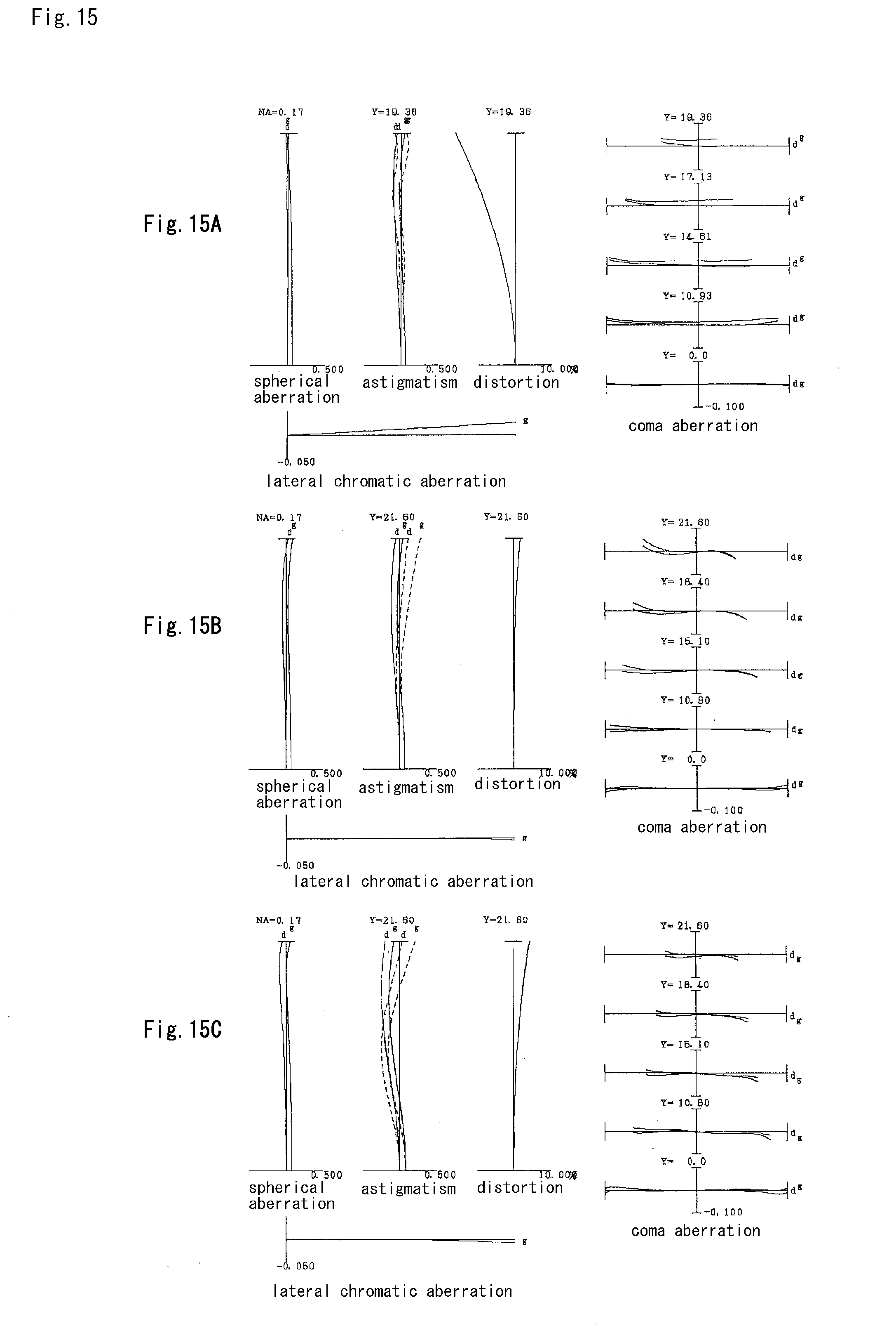
D00016

D00017
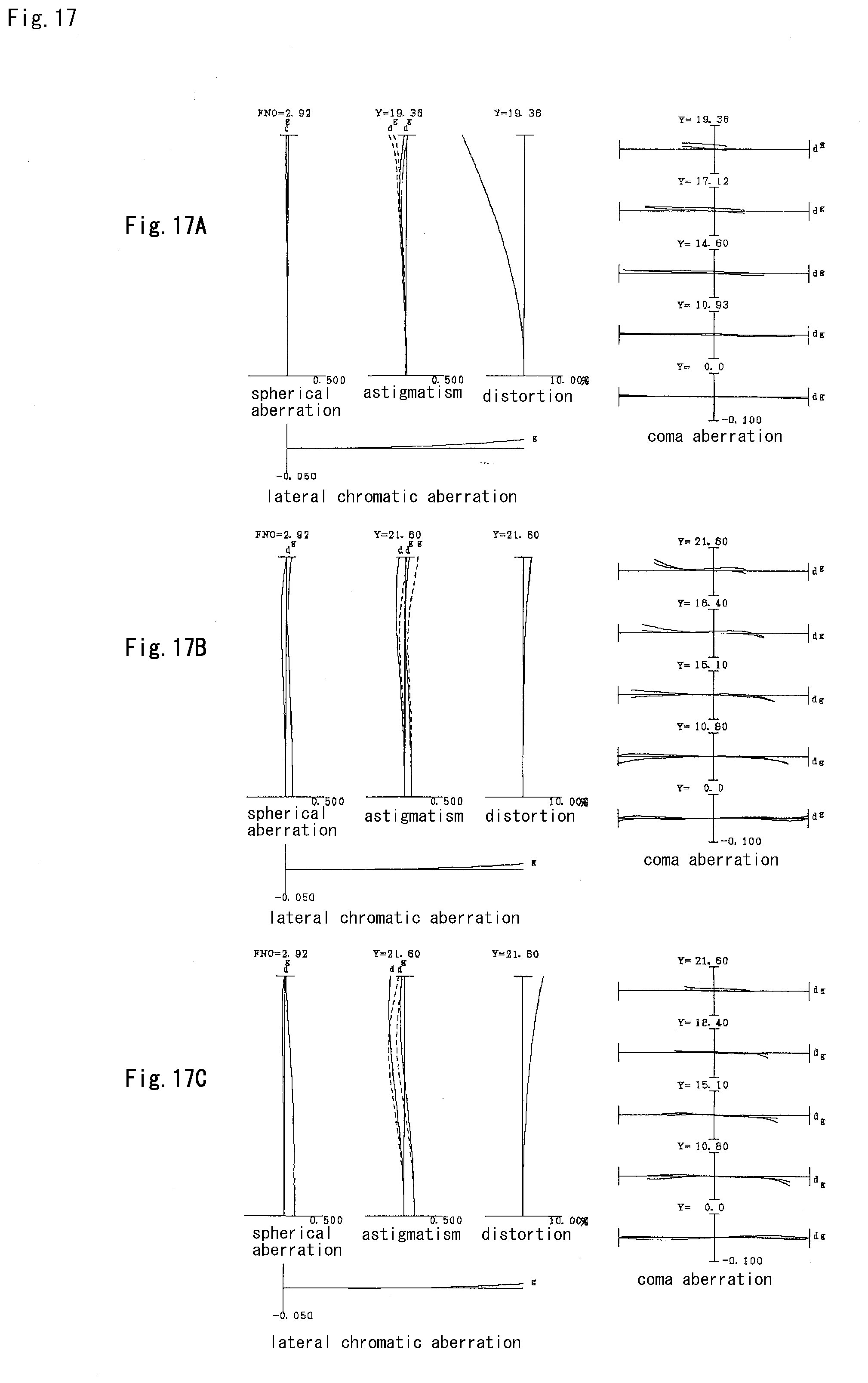
D00018
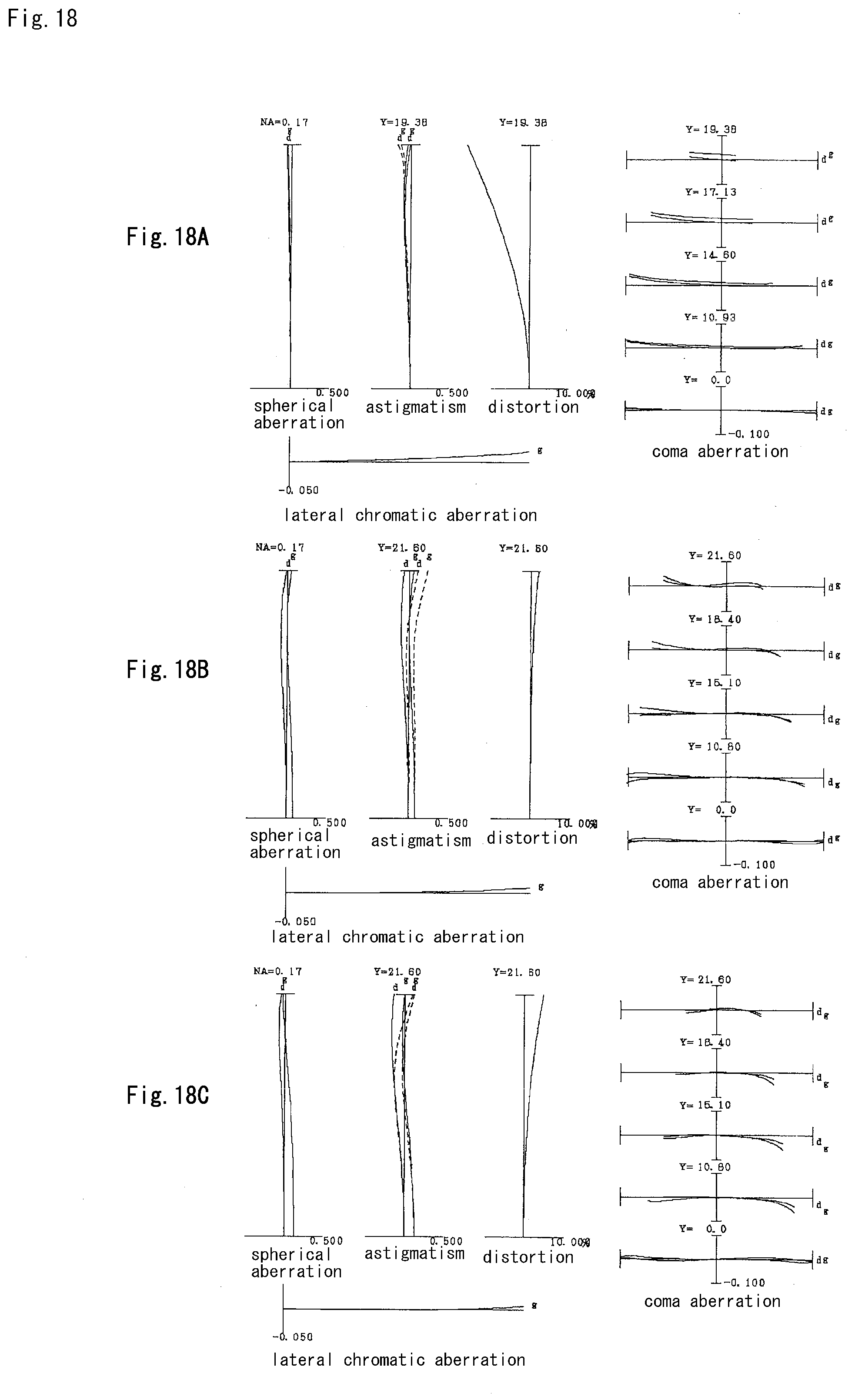
D00019
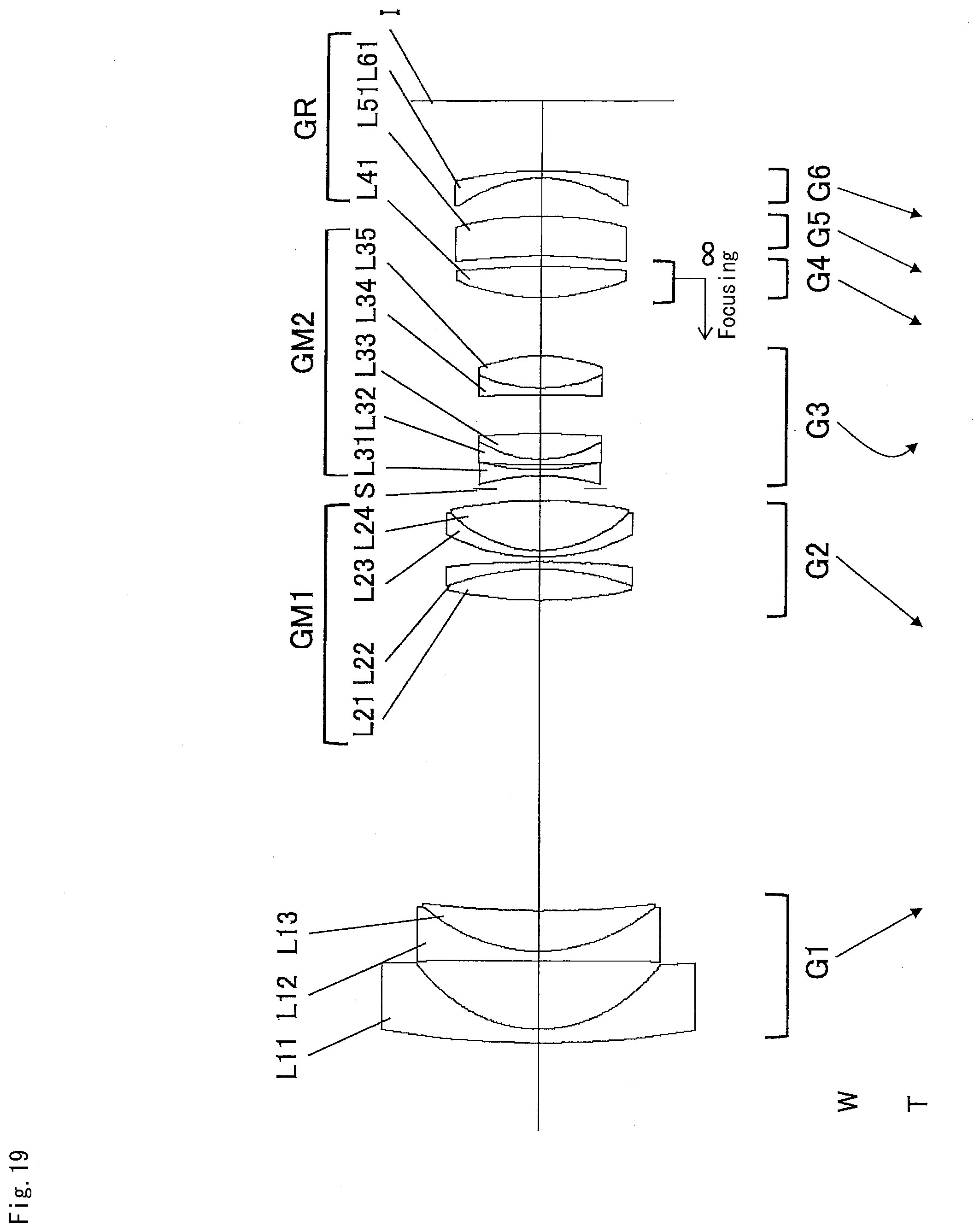
D00020
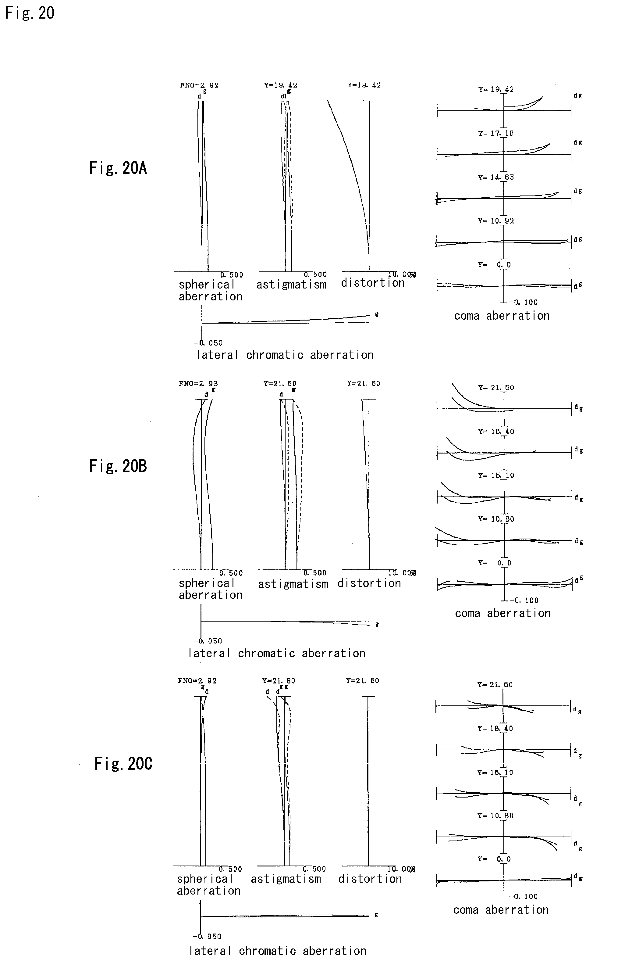
D00021

D00022

D00023

D00024
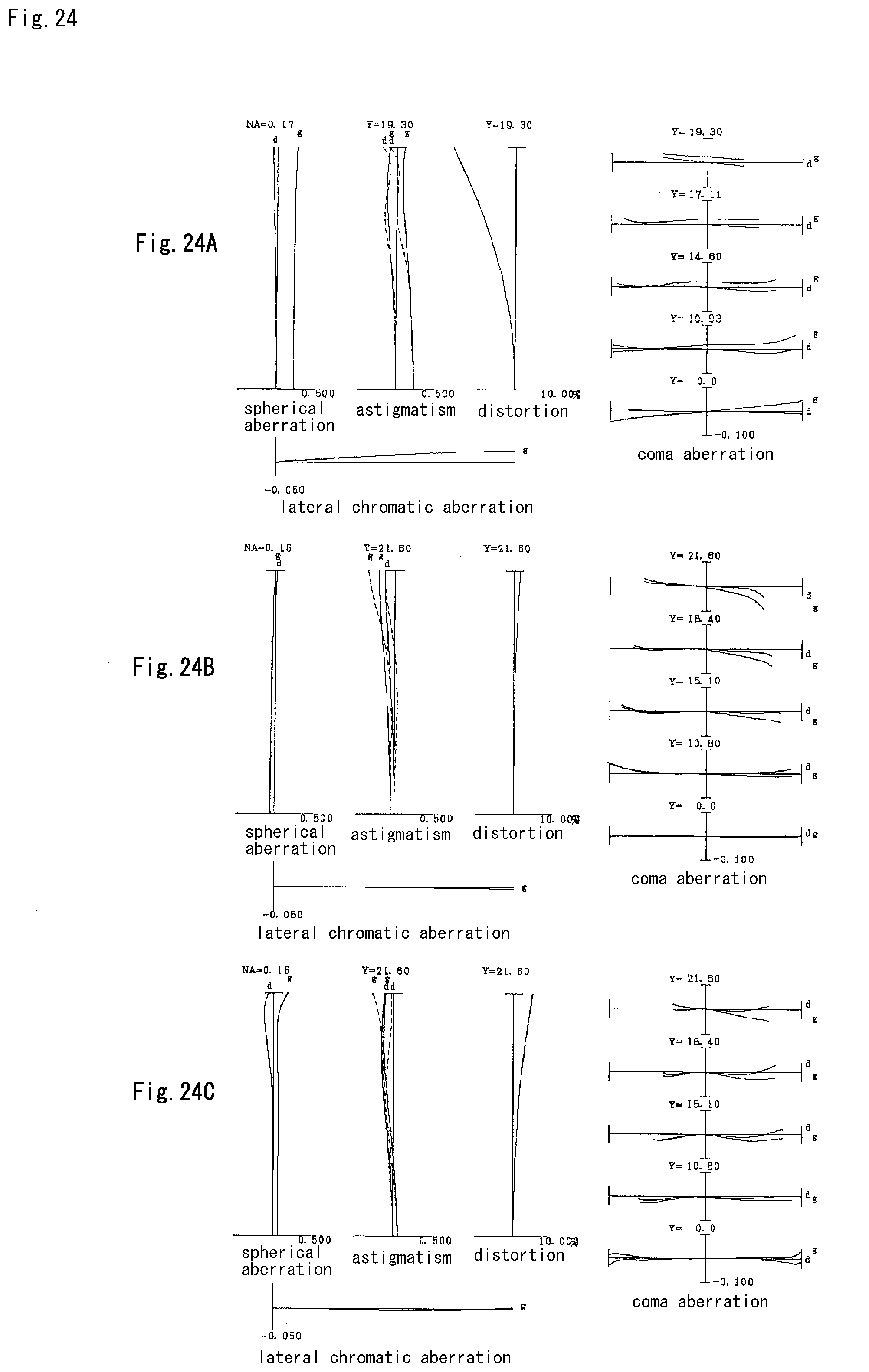
D00025

D00026
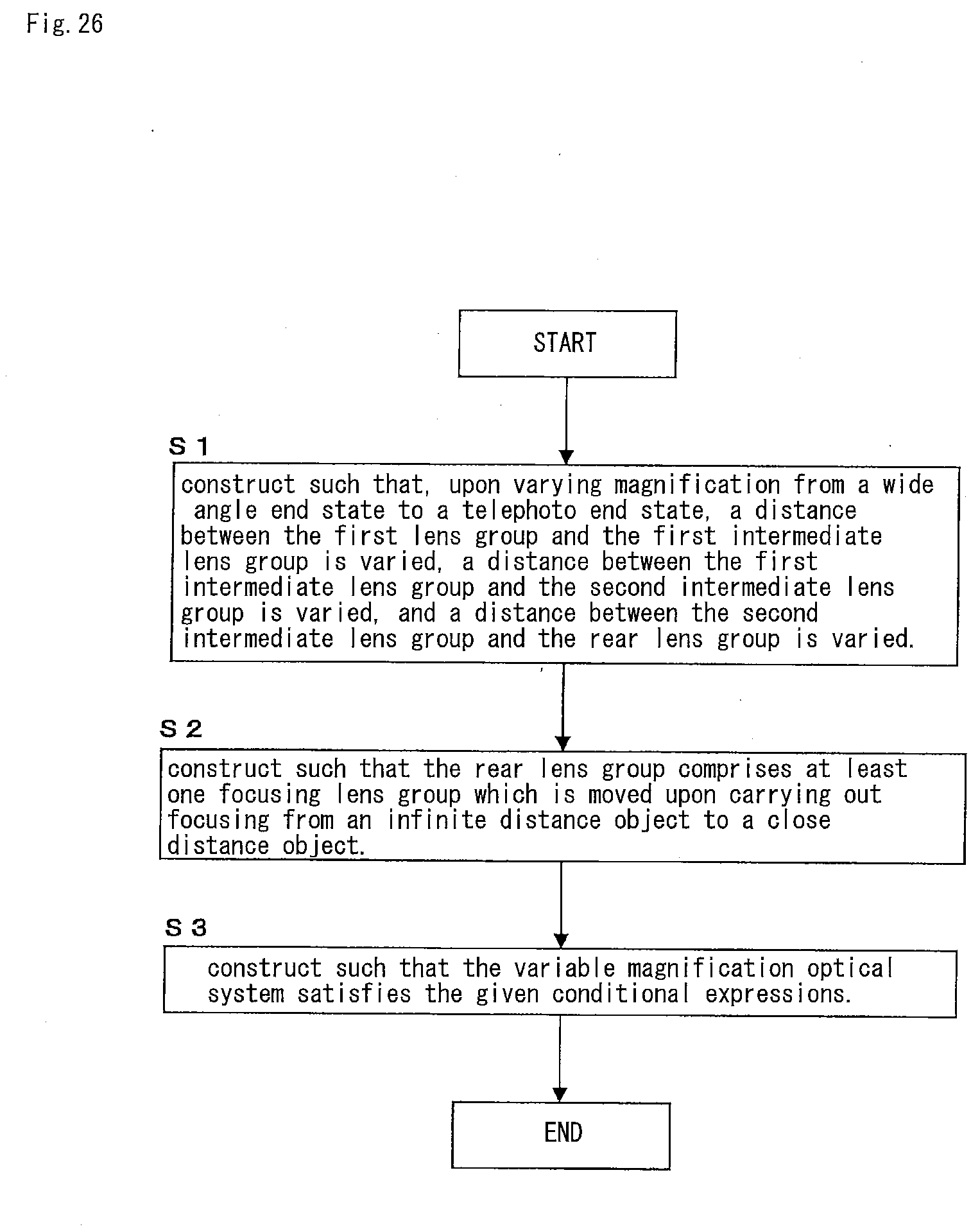
XML
uspto.report is an independent third-party trademark research tool that is not affiliated, endorsed, or sponsored by the United States Patent and Trademark Office (USPTO) or any other governmental organization. The information provided by uspto.report is based on publicly available data at the time of writing and is intended for informational purposes only.
While we strive to provide accurate and up-to-date information, we do not guarantee the accuracy, completeness, reliability, or suitability of the information displayed on this site. The use of this site is at your own risk. Any reliance you place on such information is therefore strictly at your own risk.
All official trademark data, including owner information, should be verified by visiting the official USPTO website at www.uspto.gov. This site is not intended to replace professional legal advice and should not be used as a substitute for consulting with a legal professional who is knowledgeable about trademark law.