Boresighter Trainer For Gun
Moore; Larry E. ; et al.
U.S. patent application number 16/375790 was filed with the patent office on 2020-01-23 for boresighter trainer for gun. The applicant listed for this patent is Crimson Trace Corporation. Invention is credited to Aaron Moore, Larry E. Moore.
| Application Number | 20200025503 16/375790 |
| Document ID | / |
| Family ID | 66326963 |
| Filed Date | 2020-01-23 |


| United States Patent Application | 20200025503 |
| Kind Code | A1 |
| Moore; Larry E. ; et al. | January 23, 2020 |
BORESIGHTER TRAINER FOR GUN
Abstract
A boresighter/trainer fits into a distal end of a gun barrel and includes a sound sensor, a circuit, a laser, and a power source. The boresighter/trainer has at least two operational modes: one in which it continuously emits laser light and one in which it emits laser light for a short duration when the sound of a firing pin is detected. When in its first mode, the boresighter/trainer permits laser light to be projected along the longitudinal axis of a gun barrel in which it is portioned, for the purpose of aligning a sight on the firearm. When the boresighter/trainer is in its second mode and the firing pin of the gun is activated, the sound of the firing pin is detected by the sound sensor and activates a circuit in the boresighter/trainer to cause the light source to emit light along the longitudinal axis of the firearm barrel. The boresighter/trainer may have multiple bore adapters that fit different firearm bore diameters.
| Inventors: | Moore; Larry E.; (Cottonwood, AZ) ; Moore; Aaron; (Cottonwood, AZ) | ||||||||||
| Applicant: |
|
||||||||||
|---|---|---|---|---|---|---|---|---|---|---|---|
| Family ID: | 66326963 | ||||||||||
| Appl. No.: | 16/375790 | ||||||||||
| Filed: | April 4, 2019 |
Related U.S. Patent Documents
| Application Number | Filing Date | Patent Number | ||
|---|---|---|---|---|
| 15804229 | Nov 6, 2017 | |||
| 16375790 | ||||
| 14963475 | Dec 9, 2015 | 10436553 | ||
| 15804229 | ||||
| 14459274 | Aug 13, 2014 | 9297614 | ||
| 14963475 | ||||
| Current U.S. Class: | 1/1 |
| Current CPC Class: | F41G 1/545 20130101; F41A 33/02 20130101; F41G 3/323 20130101 |
| International Class: | F41A 33/02 20060101 F41A033/02; F41G 1/54 20060101 F41G001/54; F41G 3/32 20060101 F41G003/32 |
Claims
1. A boresighter/trainer configured for use within a gun barrel of a gun, the gun barrel with a first end having a firing chamber and a second end, the boresighter/trainer comprising: (a) a body having an axis, a proximal end, a distal end configured to be inserted into the second end of the gun barrel, and a seating portion between the proximal end and the distal end, the seating portion configured to form a first contact area with an inner surface of the gun barrel; (b) a bore adapter attached to the distal end, the bore adaptor having a variable adapter diameter and configured to form a second contact area with the inner surface of the gun barrel; (c) a fastener attaching the bore adapter to the distal end, the fastener configured to apply force to the bore adapter; (d) a light source in the housing to emit a light beam aligned with the body axis; (e) a power source, (f) a sound sensor to detect the sound of a firing pin strike of the gun, and to activate a circuit in response, wherein when the circuit is activated, the power source provides power to the light source and the light source emits light; and (g) a switch, wherein the switch has a first position in which the boresighter/trainer is in a first mode whereby it constantly emits light, and the switch has a second position in which the boresighter/trainer is in a second mode whereby it emits light for a short duration when the sensor detects the sound of the firing pin strike, wherein when in the first mode, the boresighter/trainer permits laser light to be projected along a longitudinal axis of the gun barrel in which it is portioned, for aligning a sight on gun and wherein when the boresighter/trainer is in the second mode and the firing pin activated, the sound of the firing pin is detected by the sound sensor and activates the circuit in the boresighter/trainer to cause the light source to emit light along the longitudinal axis of the gun barrel.
2. The boresighter/trainer of claim 1, wherein the circuit includes a capacitor.
3. The boresighter/trainer of claim 1, wherein the bore adapter includes deformable members defining the variable adapter diameter, wherein the deformable members deform in response to force applied by the fastener.
4. The boresighter/trainer of claim 1, wherein the power source is one or more batteries.
5. The boresighter/trainer of claim 5, wherein the power source includes three batteries.
6. The boresighter/trainer of claim 1, wherein the light source is a laser.
7. The boresighter/trainer of claim 6, wherein the laser is activated for between about 7.5 to about 12.5 milliseconds, or about 0.1 seconds, when the circuit is activated.
8. The boresighter/trainer of claim 1, wherein the circuit is a 4.5 V system.
9. The boresighter/trainer of claim 1, wherein the boresighter/trainer is dimensioned to be received in either a 9 mm, .32 caliber, .38 caliber, .40 caliber, .44 caliber, .45 caliber or .50 caliber gun.
10. The boresighter/trainer of claim 1, wherein the body has an surface with a first diameter at the proximal end and a second diameter less than the first diameter at the distal end, and wherein the seating portion is a tapered section of an outer surface of the body.
11. The boresighter/trainer of claim 1, wherein the bore adapter diameter is variable.
12. The boresighter/trainer of claim 1, wherein the body distal end is tapered and the bore adapter deforming members overly the distal end, and are configured to splay and move outward from the distal end when force is applied to them by the fastener.
13. The boresighter/trainer of claim 1, wherein the body includes a first cavity having an axis aligned with the body axis, and the first cavity houses the light source.
14. The boresighter/trainer of claim 13, wherein the body includes a second cavity adjacent the first cavity, wherein the switch and power source are in the second cavity.
15. The boresighter/trainer of claim 1, wherein the proximal end of the body includes an opening from which the light source beam is projected.
16. The boresighter/trainer of claim 14, wherein the switch has a third position, and when the switch is in its third position the boresighter/trainer is in a third mode in which it is off.
17. The boresighter/trainer of claim 1, wherein the body is one piece.
18. A kit comprising the boresighter/trainer of claim 1 and one or more additional bore adaptors, wherein each of the one or more additional bore adaptors is configured to fit different-sized firearm barrels.
19. The kit of claim 18, wherein the bore adaptors fit firearms having the following bore sizes: 9 mm, .32 caliber, .38 caliber, .40 caliber, .44 caliber, .45 caliber, or .50 caliber.
Description
CROSS REFERENCE TO RELATED APPLICATIONS
[0001] This application is a continuation of U.S. patent application Ser. No. 15/804,229, filed on Nov. 6, 2017, and a continuation-in-part of U.S. patent application Ser. No. 14/963,475, filed on Dec. 9, 2015, which is a continuation-in-part of U.S. patent application Ser. No. 14/459,274, filed on Aug. 13, 2014, now U.S. Pat. No. 9,297,614, each of which are hereby incorporated by reference in their entirety.
[0002] This application incorporates by reference, to the extent they are not inconsistent with this disclosure, the disclosures of: U.S. Pat. No. 9,170,079 entitled LASER TRAINER CARTRIDGE and U.S. Pat. No. 6,421,947 entitled AXIS ALIGNMENT APPARATUS.
FIELD OF THE INVENTION
[0003] The present invention relates to a firearm boresighter that may be used to align a gun barrel with a sight on the gun; and also used for firearm training, without requiring live ammunition.
BACKGROUND OF THE INVENTION
[0004] Conventional firearm training can be dangerous, expensive (considering the prices for ammunition and replacement targets) and can only be performed in certain areas, such as shooting ranges. The present invention(s) allows firearm training to be performed safely, inexpensively, and almost anywhere without the use of live ammunition. Additionally, the present invention(s) is also a boresighter that functions to align the bore of a firearm barrel with a sight on the firearm. Until now, trainers and boresighters have been different products, requiring the owner of a firearm to purchase at least two separate products.
SUMMARY OF THE INVENTION
[0005] A laser boresighter/trainer (or just boresighter/trainer) is configured to fit inside the end of a barrel (or bore) of a firearm. A boresighter/trainer according to aspects of the invention can be activated to emit laser light that indicates where a bullet fired from the firearm would strike. The emitted light projects the longitudinal axis of the firearm barrel in which the boresighter/trainer is positioned. It can be used to align a gun's sights with the bore's longitudinal axis. It can also be used to provide realistic firearms training, preferably allowing a user to practice tap, rack, bang and/or malfunction drills. The boresighter/trainer can be configured to operate with several firearm calibers.
[0006] The boresighter/trainer comprises a body (which can be a one-piece body or a multiple-piece body). The body is elongated along an axis that is aligned with the longitudinal axis of the firearm bore when the boresighter/trainer is positioned in the gun bore. The body has a proximal end in which the laser is mounted and that remains outside of the firearm bore, and a distal end that is inserted into the firearm bore. Between the distal end and proximal end is a seating portion to form a first contact area with the inner surface of the firearm barrel at its distal end (which is the end farthest from a user and from where a fired bullet exits the barrel).
[0007] A bore adapter is attached to the distal end of the boresighter/trainer, and the bore adaptor is inserted into the gun barrel. The adapter has an outside diameter that forms a second contact area with the inner surface of the gun barrel. The first contact area and second contact area position and substantially center the boresighter/trainer in the firearm barrel, such that the body axis of the boresighter/trainer is substantially aligned with the longitudinal axis of the firearm barrel.
[0008] The boresighter/trainer has at least two modes. In a first mode, the laser is on constantly so a user can align a sight (such as an optical scope or mechanical sight) with a laser light emitted by boresighter/trainer. In this manner, the sight can be aligned with the longitudinal axis of the firearm barrel. In a second mode, the boresighter/trainer emits laser light for a short duration when it is activated by the sound of the firearm firing pin striking. The boresighter/trainer may also have a third mode in which it is turned off.
[0009] Utilizing a boresighter/trainer, the owner of a firearm need purchase only one product to (1) align a sight with the firearm barrel, and (2) train using laser light instead of live ammunition. Further, dealers could potentially reduce their inventory of products because only a single product is required for firearm bore alignment and firearm training.
BRIEF DESCRIPTION OF THE DRAWINGS
[0010] FIGS. 1A and 1B are side-views illustrating a boresighter/trainer according to aspects of the invention.
[0011] FIG. 2 illustrates the boresighter/trainer of FIGS. 1A and 1B mounted in the end of a gun barrel.
[0012] FIGS. 3A and 3B illustrate the variable diameter feature of the boresighter/trainer.
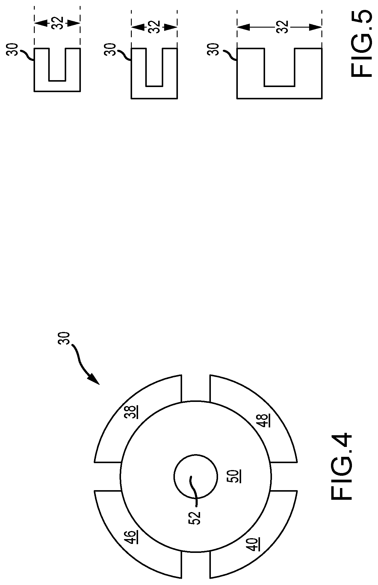
[0013] FIG. 4 illustrates an end view of a boresighter/trainer according to aspects of the invention.
[0014] FIG. 5 illustrates a plurality of different-sized bore adapters.
[0015] FIGS. 6A and 6B are partial cross-sectional views of the boresighter/trainer of FIGS. 1A and 1B, depicting the first cylindrical cavity.
[0016] FIG. 7 is a partial cross-sectional view of the switch of FIG. 6B.
[0017] FIG. 8 is a partial cross-sectional view of the body of FIG. 6A.
[0018] FIG. 9 is a top view of a boresighter/trainer according to aspects of the invention.
[0019] FIG. 10 is a side view of the boresighter/trainer of FIG. 9.
[0020] FIG. 10A is an end view of the distal end of the boresighter/trainer of FIGS. 9-10.
[0021] FIG. 10B is an end view of the proximal end of the boresighter/trainer shown in FIGS. 9-10.
[0022] FIG. 11 is a cross-sectional side view of the boresighter/trainer of FIGS. 9-10.
DETAILED DESCRIPTION OF PREFERRED EMBODIMENTS
[0023] Turning now to the Figures, where the purpose is to describe preferred embodiments of the invention and not to limit same. FIGS. 1A and 1B are side-views illustrating the present invention boresighter/trainer. The boresighter/trainer 10 includes a laser, mounted so that its beam is aligned along the axis 14 of the boresighter/trainer tool. The boresighter/trainer is positioned in a gun barrel 1 so its axis 14 is substantially aligned with axis 36 of the gun barrel.
[0024] The boresighter/trainer 10 may be configured to operate in conjunction with firearms of essentially any desired caliber. In certain embodiments, boresighter/trainer 10 is configured to fit a firearm having a caliber of 9 mm, .32 cal, .38 cal, .40 cal., .44 cal., .45 cal., or .50 cal., and many other bore sizes--particularly bore sizes for rifles. The boresighter/trainer 10 is configured to be positioned in the end of the barrel (or bore) of essentially any desired firearm having a barrel long enough to receive the boresighter/trainer. The boresighter/trainer is most preferably used in the barrel of a rifle, although it may also be used in other firearms. The Laser boresighter/trainer preferably fits barrels with a caliber of .22 to .50 caliber and preferably fits barrels 21/2 inches or longer. When in the boresighter mode it is more likely to be used in a rifle, whereas in training mode it is more likely used in a pistol. However, it could be used in any suitable firearm in either the boresighter or training mode.
[0025] Boresighter/trainer 10 comprises a body 12 with a generally elongated shape along a body axis 14. The body 12 has a proximal end 16 and a distal end 18. At the proximal end 16 the body surface has a first diameter 20, while at the distal end 18 there is a second diameter 22 which is less that the first diameter 20. Between the proximal end 16 and distal end 18 is a seating area 24. As shown, seating area 24 is a tapered portion of body 12.
[0026] FIG. 2 illustrates the boresighter/trainer of FIG. 1A or 1B mounted in a gun bore, the longitudinal axis of which is projected when the boresighter/trainer emits laser light. The seating portion 24 is tapered to form a first, contact region 26, received in a gun barrel. As shown, the seating portion 24 is a tapered outer surface of body 12. When end 16 is pushed into the bore of a gun, the tapered 24 eventually seats against the wall of the gun bore at the distal end of the gun. Potion 24 fits many bore diameters, from bores having an inside diameter as shown at numeral 28 to slightly less that the first diameter 20 (see FIGS. 1A and 1B).
[0027] Turning again to FIGS. 1A and 1B, boresighter/trainer 10 also comprises a bore adapter 30, which is attached to the distal end 18. Bore adapter 30 is preferably made out of a flexible material such as plastic or rubber. Bore adapter 30 has an adapter diameter 32. As shown in FIG. 2, the bore adapter 30 forms a second, contact area 34 with the bore's inside wall 28. The first contact region 26 and the second contact area 34 position and center boresighter/trainer 10 in the gun barrel and align body axis 12 with the bore longitudinal axis 36.
[0028] FIG. 1A shows an aspect of the boresighter/trainer wherein distal end 18 is a conically shaped part of body 12. FIG. 1B illustrates a slightly different aspect of the boresighter/trainer in which a conical shape is specifically formed into bore adapter 30. Distal end 18 may have a small chamfer to interface with the internal cone shape of the bore adapter 30 of FIG. 1B. Once the bore adapter 30 of FIG. 1B is mounted on body 12, the boresighter/trainer of FIG. 1B functions the same as the boresighter/trainer of FIG. 1A.
[0029] FIGS. 3A and 3B illustrate the variable diameter 32 feature of the bore adapter 30. The same size bore adapter 30 is shown in FIGS. 3A and 3B, and the diameter 32 in FIG. 3B is greater than in FIG. 3A. Bore adapter 30 may include deformable fingers, such as fingers 38 and 40. Although only two fingers are shown in these figures, and four fingers are shown in other figures, the boresighter/trainer is not limited to a specific number of fingers, or to using fingers. Any deformable structure that would fit into a gun barrel and pressure fit against the inside wall of the barrel could be used. For example, the bore adapter may be a cylindrical tube wherein its center expands when its two ends are compressed.
[0030] As shown best in FIG. 2, the bore adapter fingers 38 and 40 overlie the distal end 18. A fastener, such as screw 42, which is used to attach bore adapter 30 to distal end 18, may be tightened so screw head 44 presses against bore adapter 30 and forces it against distal end 18. The force causes deformation of fingers 38 and 40, which causes the fingers to expand and diameter 32 to increase as shown in FIGS. 3A and 3B. Thus, the fingers 38 and 40 are splayed in response to the force and to form the desired adapter diameter 32 for an interference fit inside of a particular diameter gun barrel.
[0031] In some aspects, as shown in FIGS. 3A and 3B, the distal end 18 second diameter 22 is tapered, with a smaller diameter at the extreme distal end 18.
[0032] FIG. 4 illustrates an end view of bore adapter 30. In this embodiment, bore adapter 30 shown in FIG. 4 has four fingers, fingers 38, 40, 46, and 48. The bore adapter 30 also includes a ring 50, or a similar structure, to accept a fastener, such as screw 42 (not shown), in a hole 52. The fingers 38, 40, 46, and 48 are axially disposed and attached to ring 50. In other aspects not shown, the ring 50 is only slightly larger than the screw hole 52, and the fingers, where attached, are not perpendicular, but are more gradually bent into a position perpendicular to the ring 50.
[0033] FIG. 5 illustrates a plurality of differently sized bore adapters 30. In order to cover a wide range of inside bore diameters it may be practical to provide a plurality of different-sized bore adapters 30, all of which have a respective, different nominal adapter diameter 32. The adaptor diameter of each adaptor 30 can be varied, such as with an adjustment of screw 42, as discussed above and shown, for example, in FIGS. 3A and 3B. A user would select a bore adapter 30 with a diameter 32 that approximately conforms with, and is slightly smaller than, the inside bore diameter of the firearm with which the boresighter/trainer 10 will be used. The nominal diameter 32 of an adapter 30 can then be modified, such as with screw 42, for a proper fit inside of the firearm bore.
[0034] FIGS. 6A and 6B are partial cross-sectional illustrations of the boresighter/trainer 10 of FIG. 1A or 1B, depicting a first cavity 60. FIG. 6A shows the first cavity 60 without components, while FIG. 6B shows the first cavity 60 with components. The first cavity 60 as shown has an axis that is aligned with body axis 12, and cavity 60 is located between the proximal end 16 and the seating portion 24 (see FIG. 1A). As shown in FIG. 6B, the first cavity 60 houses a light source 62, typically a laser, an electrically conductive spring 64, and a switch 66, which as shown is a rotary switch, although any switch can be used. The light source 62 is mounted in the housing so that it need not be removed to change batteries or to make adjustments to its alignment. Light source 62 emits a beam of light along the body axis 12. Switch 66 as shown is rotated to selectively connect the light source 62 to a power source. As is explained below, the spring keeps switch 66 in a position, either on or off, and provides an electrical path to the laser light 62. As shown in FIG. 1A, body 12 as shown includes a channel 70 formed between the body surface and the first cavity 60 to expose the switch 66. The switch 66 can be accessed to move it from one position to another through channel 70.
[0035] Also shown in FIGS. 6A and 6B, the body proximal end 16 includes a second cavity 68 connected to the first cavity 60. The second cavity 68 as shown is aligned with body axis 12 to form an opening from which a light beam is projected.
[0036] The first cavity 60 has a cavity diameter 72 (FIG. 6A). The switch 66 is a cylinder with a switch diameter 74 (see FIG. 6B), which is less than the cavity diameter 72, so that switch 66 may rotate. Switch 66 as shown has an axis substantially aligned along the body axis 12. Switch 66 can be rotated to selectively connect the power source 110 to the light source 62.
[0037] FIG. 7 is a partial cross-sectional view of the switch 66. The switch 66 has a top, or first, outside surface 80. Surface 80 as shown is disposed around switch axis 82. The first surface 80 has a conductive area 84. A conductive rod 84 is specifically shown, but other conductive structures could be used. The first surface 80 also includes a cam 86.
[0038] FIG. 8 is a partial cross-sectional view of the body 12 of FIG. 6A. The first cavity 60 has a second surface 88 which interfaces with the switch first surface 80 (shown in FIG. 7), which in this embodiment is radially disposed around body axis 12. Second surface 88 includes a second conductive area 90. An electrical connection is made between the body 12 and the switch 66 when the second conductive area 90 interfaces with the first conductive area 84 (FIG. 7). The second surface 88 also includes a channel, or recessed area 92, shown as the area in the exterior ring that is not double cross-hatched. When channel 92 receives switch cam 86, an electrical connection is made between first conductive area 84 and second conductive area 90. The conductive areas are not limited to any special shape or placement on the surface for operation. For example, the conductive areas can be centered around the axis. When cam 86 is not in channel 92, the first surface 80 and second surface 88 are forced apart, and no electrical connection is made. The shapes of cam 86 and channel 92 are not limited merely to the depicted example.
[0039] Returning to FIG. 7, switch 66 has a third outside surface 100 disposed (as shown in this embodiment) around the switch axis 82, having a third conductive area 101. If the switch 66 operates as a passive electrical conductor, the third conductive area 101 can be a conductive rod, such as the depicted first conductive area 84. In some aspects as disclosed, the conductive rod passes all the way through switch 66 from the first surface 90 to the third surface 100. Alternately, the switch can be a metal, such as aluminum, which is anodized or coated with an insulator, except for areas on first surface 80 and third surface 100 that act as conductive areas 84 and 101, so that switch 66 acts as a conductor. As explained below, switch 66 may act as a battery housing in some aspects of the invention, and the third conductive area can be considered the battery terminal, the spring 64, or the combination of battery and spring 64.
[0040] Returning to FIG. 6B, the first cavity 60 has a fourth surface 102 disposed around the body axis 12, having a fourth conductive area, which is not shown. The fourth surface can be a part of body 12, as is the second surface 88 (as shown in FIG. 8). However, as depicted in FIG. 6B the fourth surface is actually the light source 62 electrical terminal. Also as shown, the electrically conductive spring 64 is substantially aligned along the body axis 12 between the third surface 100 and fourth surface 102. Therefore, when switch 66 is "on," with the cam 86 being engaged with channel 92, the second conductive area 90 is connected to the fourth conductive area 102 through the switch 66 and spring 64.
[0041] In some aspects of the invention the power source 110 is housed elsewhere in the body 12 (not shown). The switch 66 acts as a selectively engagable conductor that completes an electrical circuit between the second conductive area 90 and fourth surface area 102, which is also conductive, from power source 110 to the light source 62, with the return ground path from light source 62 being through the electrically conductant body 12. Switch 66 may be removed through channel 70.
[0042] As shown in FIGS. 7 and 11, a power source 110 is a plurality of batteries in battery cavity 112. The power source 110 has a first polarity (+) connected to the switch's first conductive area 84 and a second polarity (-) connected to the switch's third conductive area 101. In some aspects of the invention an axial plug 114, with a center hole to admit spring 64, seals the end of battery cavity 112. The batteries are preferably insulated from the body of the boresighter/trainer 10 by a mylar sleeve 21. The laser module 62 may be of any suitable size, shape, and configuration, and may emit light of any desired shape, intensity, and color.
[0043] In one embodiment, the boresighter/trainer has a power source 100 that is three 377-type batteries, or three V393/SR754 W, or equivalent batteries to provide power to a circuit 8, which may utilize 4-4.5 V. In this embodiment, the batteries provide enough power for approximately 3,000 emissions of laser light that simulate the location of where a bullet being fired would strike.
[0044] As shown in FIG. 2, when boresighter/trainer 10 is positioned in the barrel of a firearm, proximal end 16 and the portion of body 12 that includes laser module 6, power source 110, and switch 66 are outside of the gun barrel so they may be accessed by a user.
[0045] Using known methods of making circuitry, with an appropriate circuit, the switch 66 may have two or three positions, and the boresighter/trainer could operates differently in each position. In a preferred embodiment, the switch has a first position in which the boresighter/trainer 10 has a first operating mode (or mode). In the first mode, the boresighter/trainer is constantly on, and can be used to align the bore of the firearm in which boresighter/trainer 10 is positioned with a sight of the firearm.
[0046] Switch 66 has a second position that causes boresighter/trainer 10 to operate in a second mode. In the second mode, boresighter/trainer 10 emits a burst of laser light when it detects the sound of the firing pin of the firearm striking for a time of about 100 milliseconds, although any suitable time can be used, such as any duration between 0.05 and 0.20 seconds. Or, laser 62 may be illuminated for between about 7.5 milliseconds (ms) to about 12.5 ms per shot, i.e., each time the sound of the firing pin striking activates boresighter/trainer 10. The boresighter/trainer 10 can be used for rack, bang or malfunction training drills when in the second mode. The disclosure of U.S. Publication No. 2016/0161220, entitled Master Module Light Source and Trainer, to Moore et al. and published on Jun. 9, 2016 is incorporated herein by reference to the extent it is not inconsistent with this application. Paragraphs [0072]-[0075] and FIGS. 36-38 of U.S. Publication No. 2016/0161220 in particular disclose a structure and circuitry for detecting the sound of a firing pin and activating a laser module in response.
[0047] Switch 66 may also have a third position in which boresighter/trainer 10 has a third mode in which it is off. In this embodiment, the circuitry (not shown) is implemented using a printed circuit board. Alternate embodiments of the invention may utilize any other suitable circuit to cause the laser module 62 to illuminate.
[0048] In some embodiments, the boresighter/trainer 10 may be configured to produce a sound (e.g., a gunshot sound) when in the second mode and the firing pin strikes the backer. The boresighter/trainer may include a speaker or any other suitable device to produce a sound, and may produce any desired sound.
[0049] Having thus described some embodiments of the invention, other variations and embodiments that do not depart from the spirit of the invention will become apparent to those skilled in the art. The scope of the present invention is thus not limited to any particular embodiment, but is instead set forth in the appended claims and the legal equivalents thereof. Unless expressly stated in the written description or claims, the steps of any method recited in the claims may be performed in any order capable of yielding the desired result.
* * * * *
D00000
D00001
D00002
D00003
D00004
D00005
D00006
D00007
D00008
XML
uspto.report is an independent third-party trademark research tool that is not affiliated, endorsed, or sponsored by the United States Patent and Trademark Office (USPTO) or any other governmental organization. The information provided by uspto.report is based on publicly available data at the time of writing and is intended for informational purposes only.
While we strive to provide accurate and up-to-date information, we do not guarantee the accuracy, completeness, reliability, or suitability of the information displayed on this site. The use of this site is at your own risk. Any reliance you place on such information is therefore strictly at your own risk.
All official trademark data, including owner information, should be verified by visiting the official USPTO website at www.uspto.gov. This site is not intended to replace professional legal advice and should not be used as a substitute for consulting with a legal professional who is knowledgeable about trademark law.