Suppressor with Coaxial Expansion Chambers and Tapered Seals
Parker; Joshua J.
U.S. patent application number 16/252704 was filed with the patent office on 2020-01-23 for suppressor with coaxial expansion chambers and tapered seals. The applicant listed for this patent is CGS Group, LLC. Invention is credited to Joshua J. Parker.
| Application Number | 20200025494 16/252704 |
| Document ID | / |
| Family ID | 69161016 |
| Filed Date | 2020-01-23 |


View All Diagrams
| United States Patent Application | 20200025494 |
| Kind Code | A1 |
| Parker; Joshua J. | January 23, 2020 |
Suppressor with Coaxial Expansion Chambers and Tapered Seals
Abstract
A firearm suppressor for dissipating the energy of discharge gases expelled by a discharge of a firearm has at least a first baffle and a second baffle, each baffle having a circumferential outer wall for enclosing an expansion chamber. The outer wall has a circumferential forward tapered surface and a circumferential rearward tapered surface, a taper angle of the forward tapered surface being equal to a taper angle of the rearward tapered surface. The baffles are assembled together in a coaxial baffle stack with the first baffle forward of the second baffle, the forward tapered surface of the second baffle engaging the rearward tapered surface of the first baffle for forming a tapered seal between the outer walls of the baffles, thereby limiting flow of firearm discharge gases from within the baffle stack through the tapered seal.
| Inventors: | Parker; Joshua J.; (Artesia, NM) | ||||||||||
| Applicant: |
|
||||||||||
|---|---|---|---|---|---|---|---|---|---|---|---|
| Family ID: | 69161016 | ||||||||||
| Appl. No.: | 16/252704 | ||||||||||
| Filed: | January 20, 2019 |
Related U.S. Patent Documents
| Application Number | Filing Date | Patent Number | ||
|---|---|---|---|---|
| 15368374 | Dec 2, 2016 | |||
| 16252704 | ||||
| 62261929 | Dec 2, 2015 | |||
| Current U.S. Class: | 1/1 |
| Current CPC Class: | F41A 21/30 20130101 |
| International Class: | F41A 21/30 20060101 F41A021/30 |
Claims
1. A firearm suppressor for dissipating the energy of discharge gases expelled by a discharge of a firearm, the suppressor comprising: at least a first baffle and a second baffle, each baffle having a circumferential outer wall for enclosing an expansion chamber, the outer wall having a circumferential forward tapered surface and a circumferential rearward tapered surface, a taper angle of the forward tapered surface being equal to a taper angle of the rearward tapered surface; wherein the baffles are assembled together in a coaxial baffle stack with the first baffle forward of the second baffle, the forward tapered surface of the second baffle mating with the rearward tapered surface of the first baffle for forming a tapered seal between the outer walls of the baffles, thereby limiting flow of firearm discharge gases from within the baffle stack through the tapered seal; wherein the outer wall of each baffle comprises internal threads and external threads, the internal threads of one of the baffles engaging the external threads of the other of the baffles, forming a threaded engagement for retaining the baffles together in the stack.
2. The firearm suppressor of claim 1, wherein the tapered seal is located between the expansion chambers and the threaded engagement.
3. The firearm suppressor of claim 1, wherein the threaded engagement is located between the expansion chambers and the tapered seal.
4. The firearm suppressor of claim 1, wherein for each baffle the external threads are located on a forward portion and the internal threads are located on a rearward portion.
5. The firearm suppressor of claim 1, wherein for each baffle the internal threads are located on a forward portion and the external threads are located on a rearward portion.
6. The firearm suppressor of claim 1, further comprising: a tube configured to be coupled to a firearm near a muzzle of the firearm, the baffles being located within the tube.
7. The firearm suppressor of claim 1, wherein for each baffle the rearward tapered surface forms a rearward end of the outer wall.
8. The firearm suppressor of claim 1, wherein for each baffle the forward tapered surface is rearward of a forward end of the outer wall.
9. A firearm suppressor for dissipating the energy of discharge gases expelled by a discharge of a firearm, the suppressor comprising: at least a first baffle and a second baffle, each baffle having a circumferential outer wall for enclosing an expansion chamber, the outer wall having a circumferential forward tapered surface and a circumferential rearward tapered surface, a taper angle of the forward tapered surface being equal to a taper angle of the rearward tapered surface; wherein the baffles are assembled together in a coaxial baffle stack with the first baffle forward of the second baffle, the forward tapered surface of the second baffle mating with the rearward tapered surface of the first baffle for forming a tapered seal between the outer walls of the baffles, thereby limiting flow of firearm discharge gases from within the baffle stack through the tapered seal; wherein the outer wall of each baffle comprises internal threads and external threads, the internal threads of one of the baffles engaging the external threads of the other of the baffles, forming a threaded engagement for retaining the baffles together in the stack; and wherein the tapered seal is located between the expansion chambers and the threaded engagement.
10. The firearm suppressor of claim 9, wherein for each baffle the external threads are located on a forward portion and the internal threads are located on a rearward portion.
11. The firearm suppressor of claim 9, wherein for each baffle the internal threads are located on a forward portion and the external threads are located on a rearward portion.
12. The firearm suppressor of claim 9, further comprising: a tube configured to be coupled to a firearm near a muzzle of the firearm, the baffles being located within the tube.
13. The firearm suppressor of claim 9, wherein for each baffle the rearward tapered surface forms a rearward end of the outer wall.
14. The firearm suppressor of claim 9, wherein for each baffle the forward tapered surface is rearward of a forward end of the outer wall.
15. A firearm suppressor for dissipating the energy of discharge gases expelled by a discharge of a firearm, the suppressor comprising: at least a first baffle and a second baffle, each baffle having a circumferential outer wall for enclosing an expansion chamber, the outer wall having a circumferential forward tapered surface and a circumferential rearward tapered surface, a taper angle of the forward tapered surface being equal to a taper angle of the rearward tapered surface; wherein the baffles are assembled together in a coaxial baffle stack with the first baffle forward of the second baffle, the forward tapered surface of the second baffle mating with the rearward tapered surface of the first baffle for forming a tapered seal between the outer walls of the baffles, thereby limiting flow of firearm discharge gases from within the baffle stack through the tapered seal; wherein the outer wall of each baffle comprises internal threads and external threads, the internal threads of one of the baffles engaging the external threads of the other of the baffles, forming a threaded engagement for retaining the baffles together in the stack; and wherein threaded engagement is located between the expansion chambers and the tapered seal.
16. The firearm suppressor of claim 15, wherein for each baffle the external threads are located on a forward portion and the internal threads are located on a rearward portion.
17. The firearm suppressor of claim 15, wherein for each baffle the internal threads are located on a forward portion and the external threads are located on a rearward portion.
18. The firearm suppressor of claim 15, further comprising: a tube configured to be coupled to a firearm near a muzzle of the firearm, the baffles being located within the tube.
19. The firearm suppressor of claim 15, wherein for each baffle the rearward tapered surface forms a rearward end of the outer wall.
20. The firearm suppressor of claim 15, wherein for each baffle the forward tapered surface is rearward of a forward end of the outer wall.
Description
CROSS-REFERENCE TO RELATED APPLICATIONS
[0001] This application is a continuation-in-part of U.S. patent application Ser. No. 15/368,374, filed on Dec. 2, 2016, and titled SUPPRESSOR WITH COAXIAL EXPANSION CHAMBERS AND TAPERED SEALS, the content of which is incorporated by reference. This application claims the benefit of the filing date of U.S. Provisional Patent Application Ser. No. 62/261,929, filed on Dec. 2, 2015, and titled SUPPRESSOR WITH COAXIAL EXPANSION CHAMBERS AND TAPERED SEALS, the content of which is incorporated by reference.
BACKGROUND
[0002] Firearm suppressors are used to reduce, or muffle, the external sound signature by dissipating the energy of the gases produced in a firearm discharge. A typical suppressor has multiple internal baffles for directing high-velocity gases into expansion chambers of the suppressor and/or retaining the gases within the chambers.
BRIEF DESCRIPTION OF THE DRAWINGS
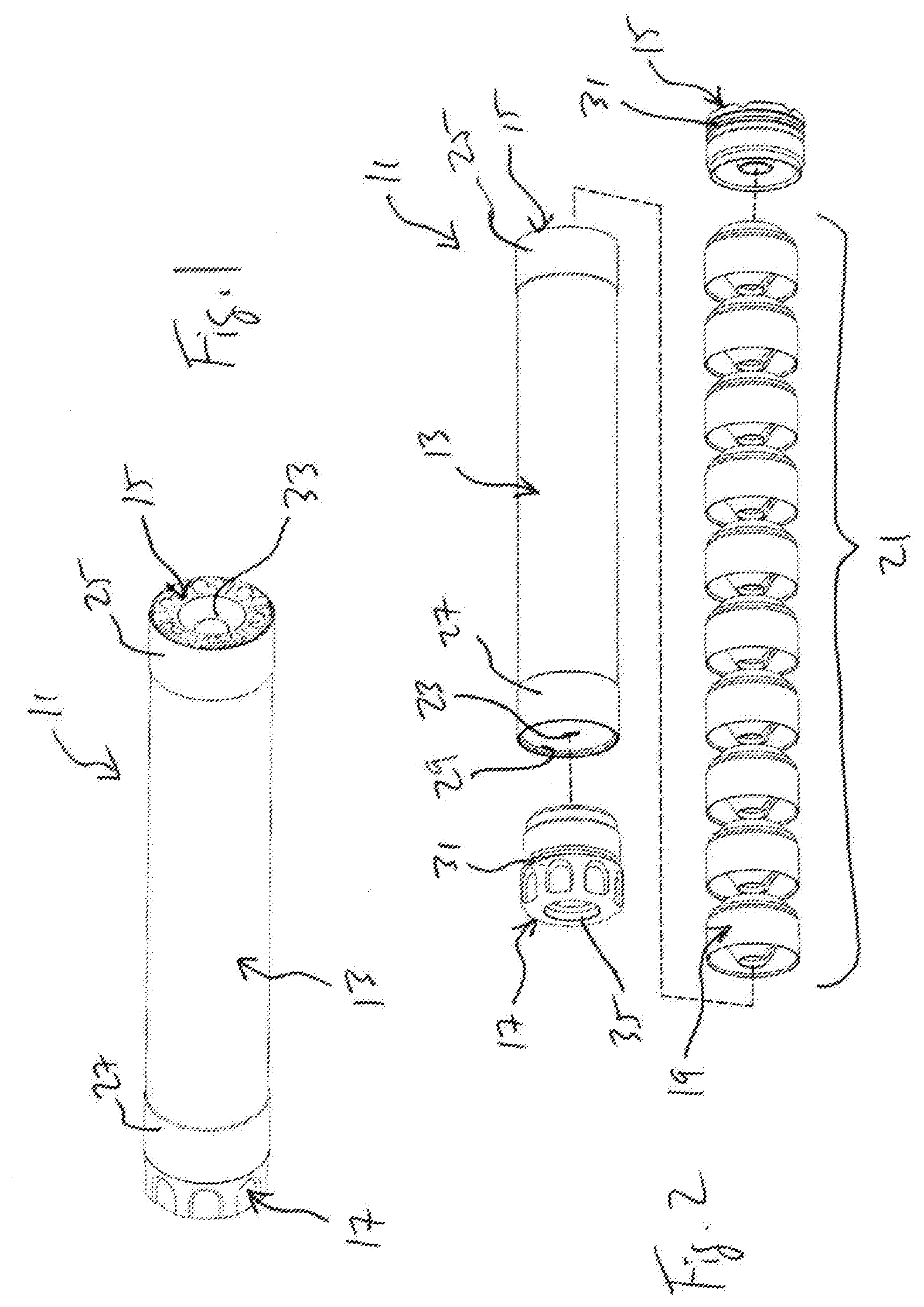
[0003] FIG. 1 is an oblique view of a firearm suppressor according to this disclosure.
[0004] FIG. 2 is an oblique exploded view of the suppressor of FIG. 1.
[0005] FIGS. 3 and 4 are oblique views of a baffle of the suppressor of FIG. 1.
[0006] FIG. 5 is a cross-section view of the baffle of FIG. 3.
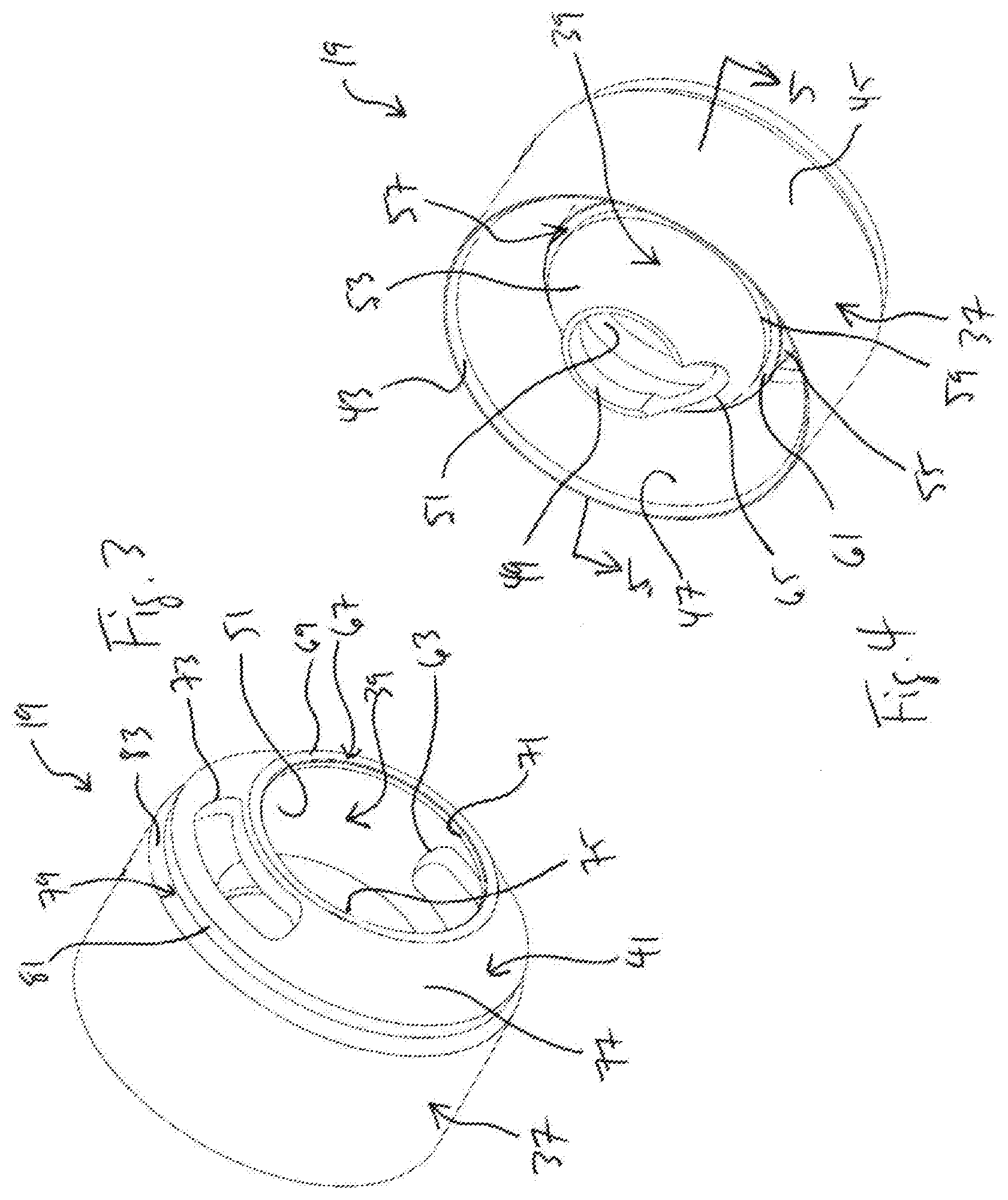
[0007] FIG. 6 is a cross-section side view of the suppressor of FIG. 1.
[0008] FIG. 7 is an enlarged cross-section side view of a portion of the suppressor of FIG. 1.
[0009] FIG. 8 is an enlarged cross-section side view of a rear portion of the suppressor of FIG. 1.
[0010] FIG. 9 is an enlarged cross-section side view of a front portion of the suppressor of FIG. 1.
[0011] FIG. 10 is a cross-section side view of an alternative embodiment of a suppressor according to this disclosure.
[0012] FIG. 11 is an enlarged cross-section side view of a portion of the suppressor of FIG. 10.
[0013] FIG. 12 is a cross-section side view of another alternative embodiment of a suppressor according to this disclosure.
[0014] FIG. 13 is an enlarged cross-section side view of a portion of the suppressor of FIG. 12.
[0015] FIG. 14 is a cross-section side view of another alternative embodiment of a suppressor according to this disclosure.
[0016] FIG. 15 is an enlarged cross-section side view of a portion of the suppressor of FIG. 14.
[0017] FIG. 16 is a cross-section side view of another alternative embodiment of a suppressor according to this disclosure.
[0018] FIG. 17 is an enlarged cross-section side view of a portion of the suppressor of FIG. 16.
[0019] FIG. 18 is a cross-section side view of another alternative embodiment of a suppressor according to this disclosure.
[0020] FIG. 19 is an enlarged cross-section side view of a portion of the suppressor of FIG. 18.
[0021] FIG. 20 is an enlarged cross-section side view of another alternative embodiment of a portion of a suppressor according to this disclosure.
[0022] FIG. 21 is a cross-section side view of an assembly of two suppressor baffles according to this disclosure.
[0023] FIG. 22 is a cross-section side view of an alternative embodiment of an assembly of two suppressor baffles according to this disclosure.
[0024] FIG. 23 is a cross-section side view of another alternative embodiment of an assembly of two suppressor baffles according to this disclosure.
[0025] FIG. 24 is a is a cross-section side view of another alternative embodiment of an assembly of suppressor baffles according to this disclosure.
[0026] FIG. 25 is a partial cross-section side view of an assembly of suppressor baffles as shown in FIG. 24.
DETAILED DESCRIPTION
[0027] In the specification, reference may be made to the spatial relationships between various components and to the spatial orientation of various aspects of components as the devices are depicted in the attached drawings. However, as will be recognized by those skilled in the art after a complete reading of this disclosure, the devices, members, apparatuses, etc. described herein may be positioned in any desired orientation. Thus, the use of terms such as "above," "below," "upper," "lower," "forward," "rearward," or other like terms to describe a spatial relationship between various components or to describe the spatial orientation of aspects of such components should be understood to describe a relative relationship between the components or a spatial orientation of aspects of such components, respectively, as the device described herein may be oriented in any desired direction.
[0028] This disclosure describes an improved firearm suppressor having coaxial expansion chambers and tapered seals between adjacent baffles. Baffles within a suppressor tube are assembled into a coaxial "stack" and have a shape for cooperating to form central expansion chambers and coaxial expansion chambers. Also, a circumferential forward tapered surface and a circumferential rearward tapered surface are each formed on an outer wall of each baffle, the tapered surfaces of adjacent baffles engaging to form a tapered seal for preventing or limiting the flow of firearm discharge gases, and entrained particulates, from within the baffle stack through the tapered seal. In addition, the tapered seal provides for increasing sealing force as adjacent baffles are compressed together within the stack. Circumferential tapered surfaces are also preferably formed on each end cap of the suppressor for engaging the corresponding tapered surfaces of baffles adjacent the caps, thereby forming a tapered seal.
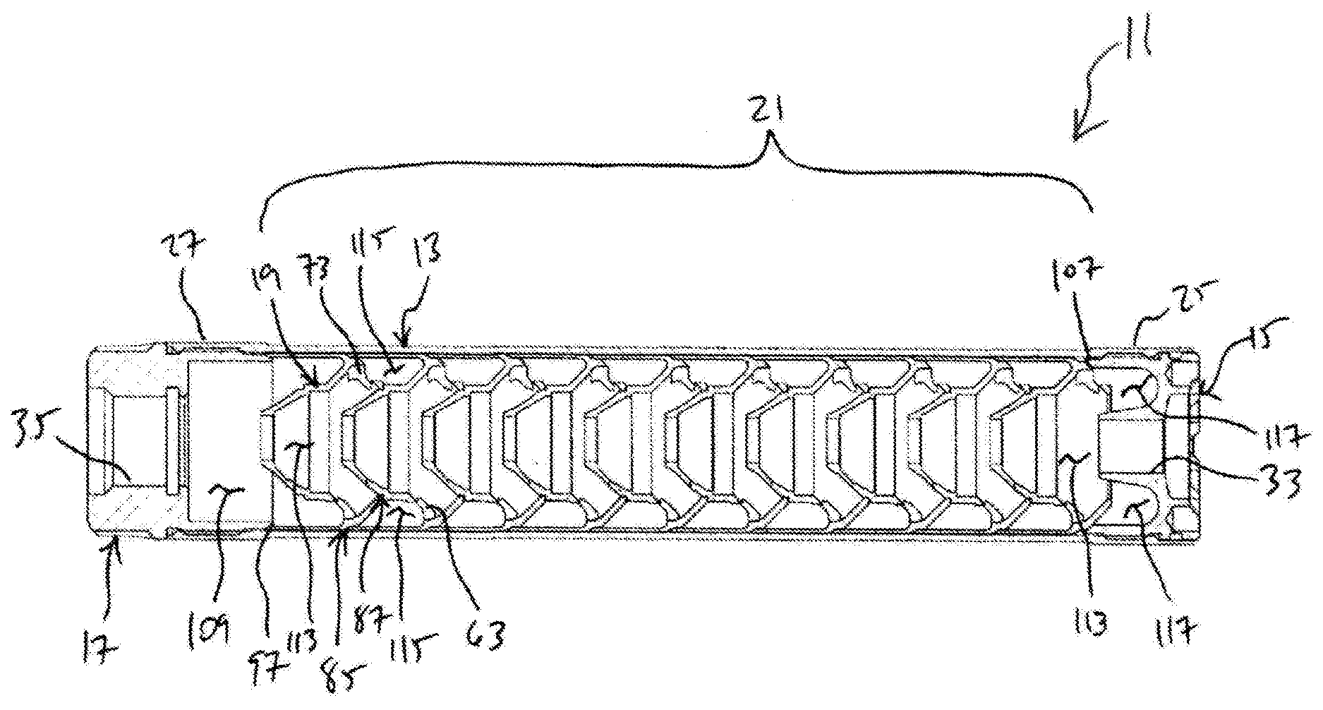
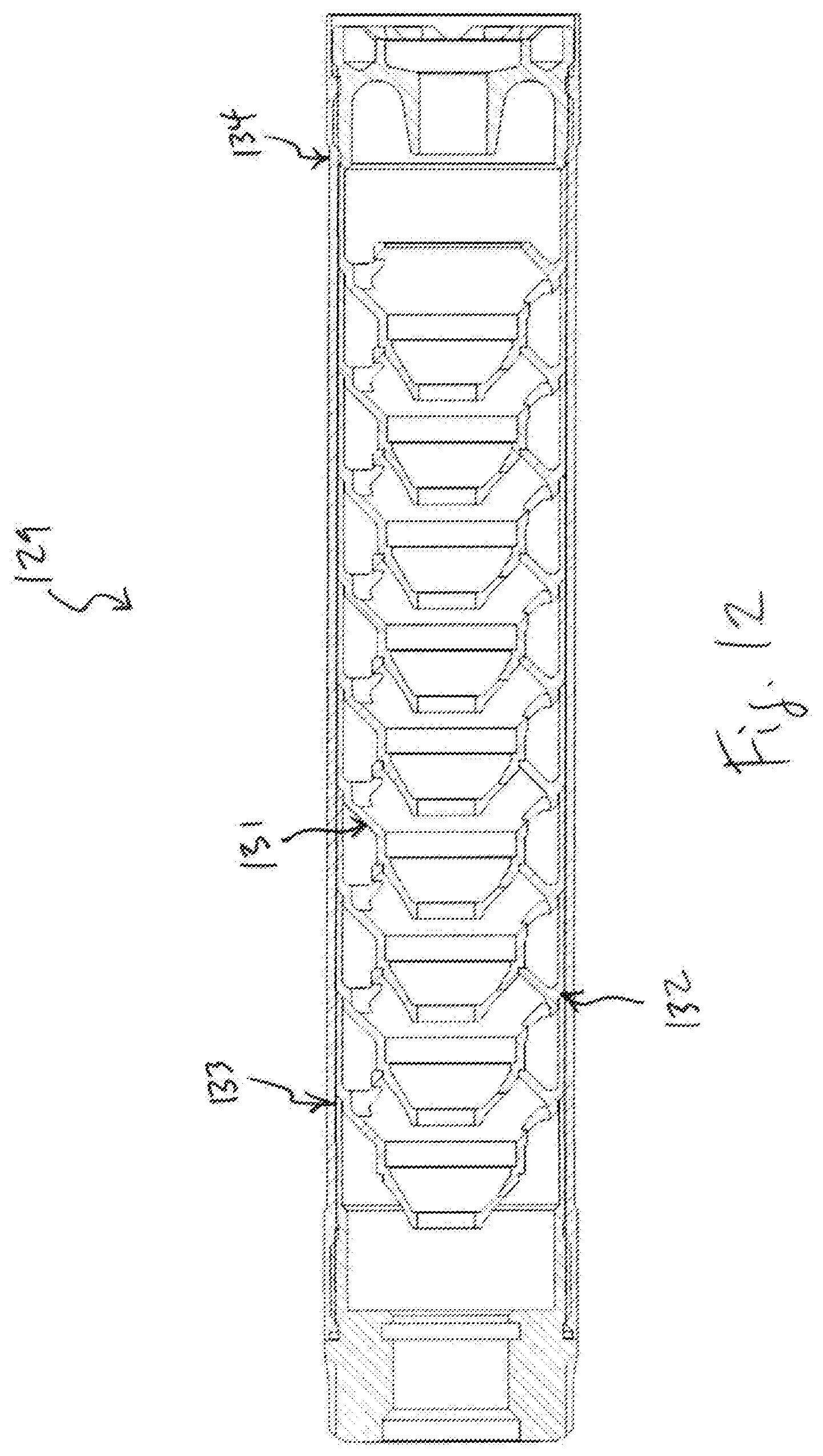
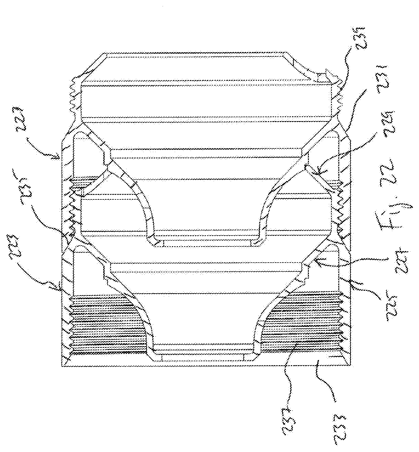
[0029] FIGS. 1 through 9 illustrate a preferred embodiment of a firearm suppressor 11 according to this disclosure, suppressor 11 having central expansion chambers, coaxial expansion chambers, and tapered seals between adjacent baffles.
[0030] Suppressor 11 is shown assembled In FIG. 1 and in an exploded view in FIG. 2. Suppressor 11 comprises a tube 13, front end cap 15, rear end cap 17, and multiple baffles 19 assembled together to form a coaxial baffle stack 21. Tube 13 is shown as having a generally cylindrical, hollow, tubular form, though tube 13 may have another configuration in alternative embodiments. Tube 13 has an inner surface 23 and cylindrical ends 25, 27, each end 25, 27 having internal threads 29. Cylindrical end caps 15, 17 have corresponding external threads 31, allowing for end caps 15, 17 to be assembled with tube 13. For a tube 13 having a shape other than cylindrical, alternative methods for retaining end caps 25, 27 will be used. Front end cap 15 has a bore 33 and read end cap 17 has a bore 35, bores 33, 35 being aligned with the muzzle of a firearm when suppressor 11 is installed thereon, allowing for a projectile fired from the firearm to pass through bore 35, baffle stack 21, and bore 33. Rear end cap 17 is preferably configured to engage the barrel of a firearm or a mounting device attached to the firearm, thereby coupling suppressor 11 to the firearm.
[0031] FIGS. 3 and 4 are enlarged oblique views of a baffle 19, and FIG. 5 shows a cross-section of baffle 19 taken along plane 5-5 of FIG. 4. Baffle 19 is preferably formed from metal and preferably as a unitary structure. As visible in FIG. 5, baffle 19 is a modified M-style baffle and comprises an outer wall 37, a central cone 39, and a chamber wall 41. In the embodiment shown, baffle 19 is cylindrical, though baffle 19 (or particular features thereof) may be formed to have another shape in alternative embodiments, such as those in which tube 13 has a non-cylindrical shape. Features will be described as circumferential for a cylindrical embodiment, though similar features for non-cylindrical embodiments should be understood to be on or near the periphery.
[0032] Outer wall 37 is a thin circumferential wall that extends rearward from chamber wall 41 and terminates in a tapered surface 43 at the rearward end of wall 37. In the preferred embodiment, the angle of tapered surface 43 is 30 degrees and is measured from outer surface 45 of wall 37. Inner surface 47 of wall 37 is spaced from cone 39 for forming an expansion chamber, discussed below, between inner surface 47 and cone 39. In this and other embodiments, particular values for angles of features may be shown or described, though it should be noted that other values of angles may be used. For example, tapered surface 43 is shown and described as having a 30-degree taper angle, though other values in the range of 0<.theta.<90 may be used.
[0033] Cone 39 extends rearward generally from a forward end of outer wall 37 and is formed to have a shape approximating a thin-wall frustum. A bore 49 is located at a rearward portion of cone 39 and is sized to allow a projectile to pass through bore 49 when fired from an attached firearm. Bore 49 is preferably sized to provide the minimum required clearance for allowing a projectile of selected maximum size to pass through, while preventing contact of the projectile with bore 39. An inner surface 51 extends from bore 49 to chamber wall 41, whereas an outer surface of cone 39 is divided into rearward outer surface 53 and forward outer surface 55. In the preferred embodiment, a 90-degree circumferential shoulder 57 is formed between surfaces 53 and 55 on the outside of cone 39, shoulder 57 having an outward-facing surface 59 and a rearward-facing surface 61. A gas port 63 is formed in a forward portion of cone 39, the port extending through cone 39 between forward outer surface 55 and inner surface 51. As shown, an optional gas passage 65 in the rear portion of cone 39 intersects bore 49.
[0034] In this embodiment, chamber wall 41 extends forward and inward at a 45-degree angle generally from the intersection of outer wall 37 and cone 39. Wall 41 is formed as a thin-wall frustum and terminates with a 90-degree shoulder 67 formed by forward-facing surface 69 and inward-facing surface 71. A gas port 73 extends through wall 41 between an inner surface 75 and an outer surface 77, and port 73 is preferably located on the opposite side of bore 49 to port 63 of cone 39. In an alternative embodiment, gas port 73 intersects and interrupts shoulder 67, allowing for a protrusion, flat, or other feature on an adjacent baffle 19 to engage a portion of port 73 for rotational alignment of baffles 19 in baffle stack 21. A circumferential tapered shoulder 79 is formed generally at the intersection of outer wall 37 and chamber wall 41. Shoulder 79 has an outward-facing surface 81 and a 30-degree tapered surface 83 (150 degrees from surface 81), such that tapered surface 83 is recessed rearward from outer surface 77 of chamber wall 41 at the forward end of outer wall 37.
[0035] FIG. 6 is a cross-section side view of assembled suppressor 11, with baffles 19 arranged in baffle stack 21 within tube 13. Front end cap 15 is installed in forward end 25 of tube 13, and rear end cap 17 is installed in rear end of tube 13. Caps 15, 17 move toward each other as they are threaded into tube 13, and this causes caps 15, 17 to compress baffles 19 together in stack 21. Adjacent baffles 19 are in contact with each other at selected mating surfaces to form baffle seals, the seals defining chambers within suppressor 11.
[0036] Referring also to FIGS. 6 through 9, outer baffle seal 85 is a circumferential, tapered seal formed from the mating of tapered surface 43 of a first baffle 19 to tapered shoulder 79 of an adjacent second baffle 19 to the rear of first baffle 19. Tapered surface 43 of first baffle 19 mates with tapered surface 83 of second baffle 19, and inner surface 47 of first baffle is located near outward-facing surface 81 of second baffle 19. Outer baffle seal 85 provides a positive sealing arrangement for preventing or limiting gases and particulates within baffle stack 21 from escaping through outer baffle seal 85. Outer baffle seal 85 also has the advantage of providing for increasing sealing force as baffle stack is compressed by end caps 15, 17, in which tapered surface 43 and tapered surface 83 engage with greater force as caps 15, 17 are moved toward each other.
[0037] Eliminating or minimizing passage of discharge gases and entrained particulates through outer baffle seal 85 prevents fouling and carbon buildup on outer surface 45 of baffle 19 and on inner surface 23 of tube 13. In previous suppressor designs, fouling and carbon buildup can prevent easy removal of the baffle stack from within the suppressor tube and may require tools, such as a hammer, and application of significant force to dislodge and remove the baffles. In suppressor 11, the enhanced tapered seal of outer baffle seal 85 prevents fouling and carbon buildup, allowing for easy removal of baffles 19 from within tube 13.
[0038] In the preferred embodiment, inner baffle interface 87 is a circumferential, non-tapered arrangement formed from the positioning of shoulder 57 of the first baffle 19 close to shoulder 67 of the adjacent second baffle 19 to the rear of first baffle 19. Rearward-facing surface 61 of first baffle 19 lies near forward-facing surface 69 of second baffle 19, and outward-facing surface 59 of first baffle 19 lies near inward-facing surface 71 of second baffle. Inner baffle interface 87 provides two narrow annular spaces for limiting gases and particulates from moving through inner baffle interface 87.
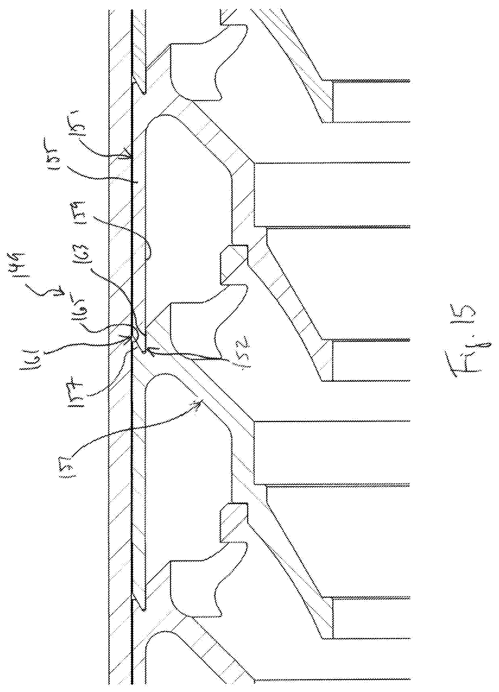
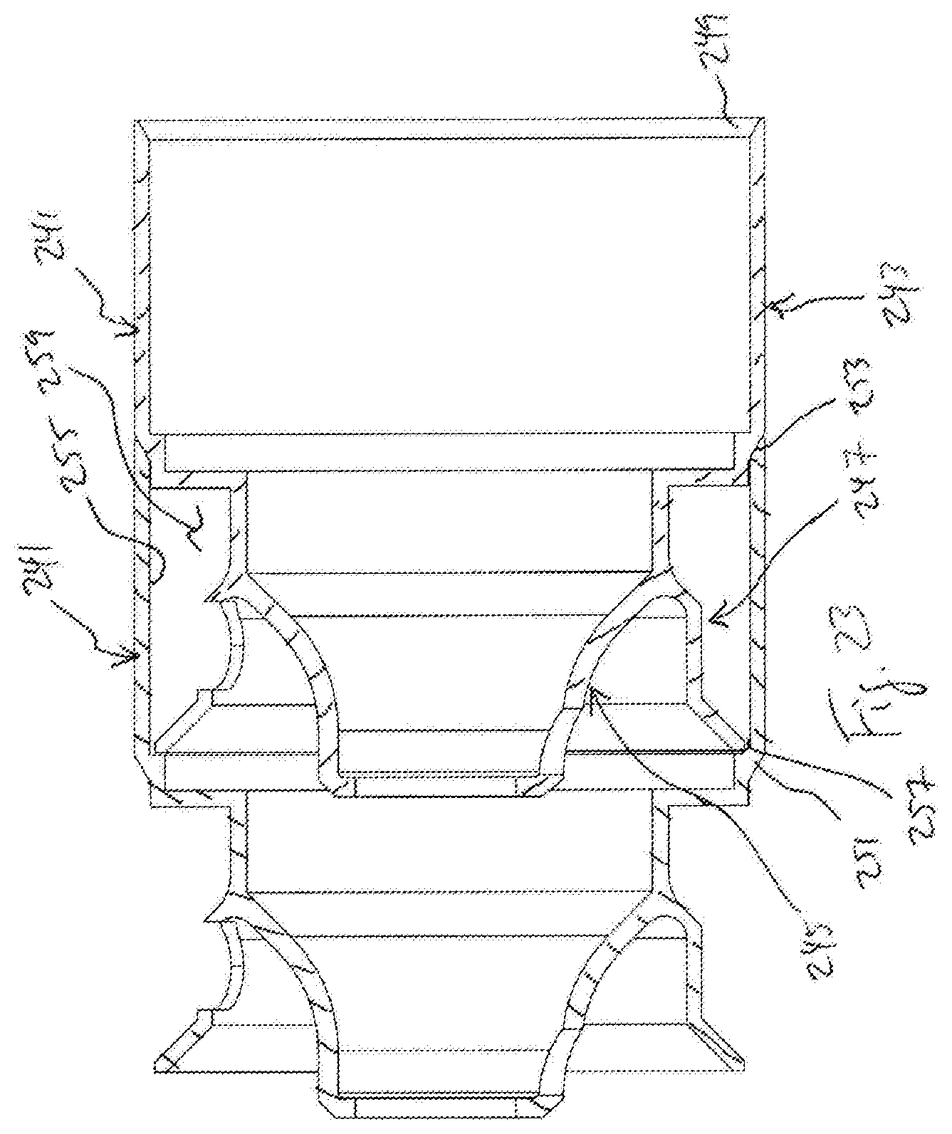
[0039] Referring specifically to FIG. 8, the rear portion of suppressor 11 is shown in side cross-section with rear end cap 17 installed in end 27. Threads 31 of cap 17 engage threads 29 of tube 13 for retaining cap 17 in tube 13. Threads 31 are formed on a cylindrical wall 89, which extends forward from adapter section 91. To seal cap 17 to rearmost baffle 19, a 30-degree tapered surface 93 is formed on the forward end of wall 89, and the taper angle is measured from inner surface 95 of wall 89. This orientation allows tapered surface 93 of cap 17 to mate against tapered surface 43 of rearmost baffle 19, creating a tapered seal 97. Seal 97 prevents gases and particulates from escaping through seal 97 and causing fouling and carbon buildup in threads 29, 31.
[0040] Referring specifically to FIG. 9, the front portion of suppressor 11 is shown in side cross-section with front end cap 15 installed in end 25. Threads 31 of cap 15 engage threads 29 of tube 13 for retaining cap 15 in tube 13. Threads 31 are formed on a cylindrical wall 99, which extends rearward from end section 101. In addition, a diverter cone 103 extends rearward from end section 101, bore 33 extending through diverter 103. To seal cap 15 to front baffle 19, a 45-degree tapered surface 105 is formed on the rearward end of wall 99, and the tapered angle is measured from the outer surface of wall 99. This orientation allows tapered surface 105 of cap 15 to mate against outer surface 77 of chamber wall 41 of front baffle 19, creating a tapered seal 107. Seal 107 prevents or limits gases and particulates from escaping through seal 107 and causing fouling and carbon buildup in threads 29, 31.
[0041] Referring again to FIGS. 5 through 9, caps 15, 17 and baffles 19 cooperate to form expansion chambers within suppressor 11, the chambers redirecting, slowing, and/or trapping gases and particulates that enter suppressor through bore 35 of rear cap 17. A first chamber 109 is defined by outer wall 89 of cap 17 and outer surfaces 53, 55 of cone 39 of rearmost baffle 19. Gases 111, indicated by arrows, enter chamber 109, and a portion of gases 111 is diverted around cone 39 and slowed, but the diverted gases can then exit chamber 109 through port 63 and pass into the adjacent central chamber 113.
[0042] Between each pair of baffles 19, a central chamber 113 is defined by inner surface 51 of cone 39 of the rearward baffle 19, inner surface 75 of chamber wall 41 of the rearward baffle 19, and outer surface 53 of cone 39 of the forward baffle 19. A portion of gases 111 entering each chamber 113 is diverted around cone 39 and enters a coaxial chamber 115 through port 73. Each coaxial chamber 115 is defined by outer surface 77 of chamber wall 41 of the rearward baffle 19, inner surface 41 of outer wall 37 of forward baffle 19, and outer surface 55 of cone 39 of forward baffle 19. The portion of gases 111 diverted into each coaxial chamber 115 flows around chamber 115 to port 63 and exits into the next central chamber 113.
[0043] Gases that continue to the forward portion of suppressor 11 enter central chamber 113 between front baffle 19 and front end cap 15. However, unlike interface 87 between adjacent baffles 19, diverter cone 103 has a smaller diameter than that of inward-facing surface 71 of chamber wall 41, and this allows a portion of gases to flow into a forward chamber 117, the gases flowing between chamber wall 41 and cone 103 and through port 73.
[0044] With the number of chambers 113, 115, 117 along the length of suppressor 11, and with turbulence induced from the flow of gases through ports 63, 73 and around chambers 115, a significant portion of gases 111 are trapped and slowed, dissipating momentum and thermal energy within suppressor 11 before the gases exit bore 33 of front end cap 17. The performance of suppressor 11 can be modified by changing the numbers of baffles 19, the sizes and number of ports 63, 73, and the sizes of chambers 113, 115, 117.
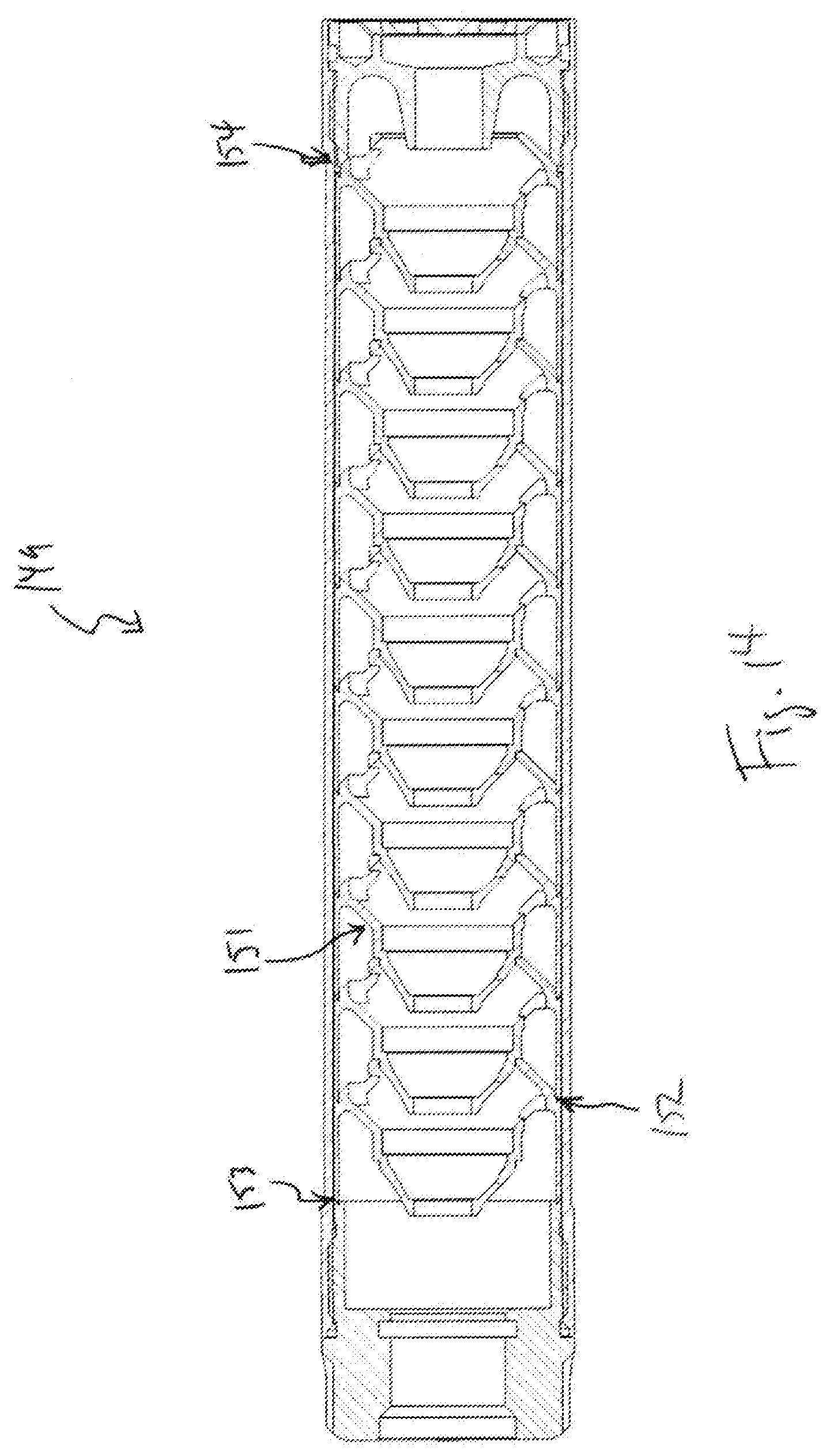
[0045] FIGS. 10 through 20 illustrate alternative embodiments of baffles forming tapered seals in a suppressor and according to this disclosure. The suppressors in these embodiments have a configuration similar to that of suppressor 11 and operate in the same manner. The only changes of note are the tapered seal configurations between adjacent baffles and between baffles and end caps, and the discussion will be limited to these alternatives while incorporating the above discussion for suppressor 11.
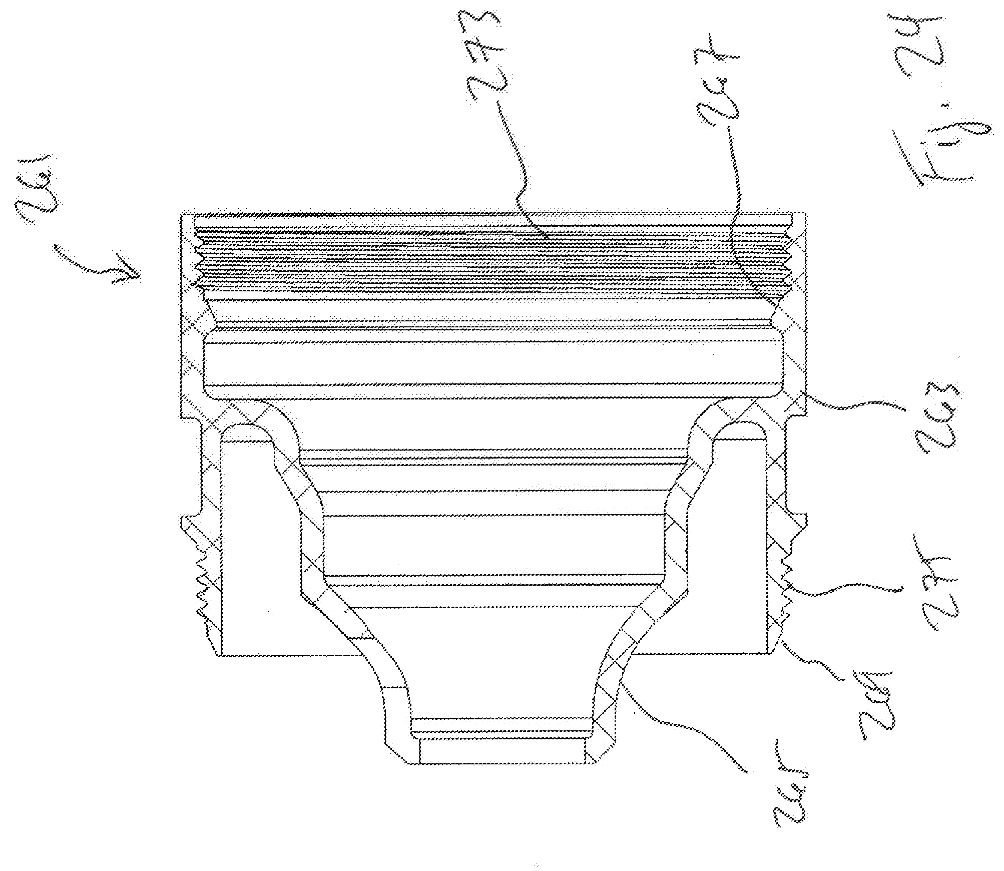
[0046] FIGS. 10 and 11 illustrate a suppressor 119 having baffles 121 that form a non-recessed, tapered outer baffle seal 122 when assembled together. A similar seal 123 is formed between rear baffle 121 and the rear end cap, and a tapered seal 124 is formed with front baffle 121 and the front end cap. Rather than a recessed tapered seal, as with seal 85 of suppressor 11, seal 122 is formed by a tapered surface 125 mating with outer surface 127 of the chamber wall of baffle 121. Seal 122 provides for only one mating interface.
[0047] FIGS. 12 and 13 illustrate a suppressor 129 having baffles 131 that form a recessed, tapered outer baffle seal 132 when assembled together. A similar seal 133 is formed between rear baffle 131 and the rear end cap, and a tapered seal 134 is formed with front baffle 131 and the front end cap. Seal 132 is an inverted version of seal 85 of suppressor 11, in that an outer wall 135 extends forward from chamber wall 137 of each baffle and terminates in a tapered surface 139. A recessed shoulder 141 is formed by outward-facing surface 143 and a tapered surface 145. Seal 132 is formed by tapered surface 139 mating with tapered surface 145, with outward-facing surface 143 being near inner surface 146 of outer wall 135. In this configuration, adjacent baffles 131 form coaxial chambers 147 between forward-extending outer wall 135 of rearward baffle 131, cone section 148 of forward baffle 131, and chamber wall 137 of rearward baffle 131.
[0048] FIGS. 14 and 15 illustrate a suppressor 149 having baffles 151 that form a recessed, tapered outer baffle seal 152 when assembled together. A similar seal 153 is formed between rear baffle 151 and the rear end cap, and a tapered seal 154 is formed with front baffle 151 and the front end cap. Seal 152 is a recessed tapered seal much like seal 85 of suppressor 11, but seal 152 has a reversed taper angle. Outer wall 155 has a tapered surface 157 on its rearward end, the taper angle being measured from inner surface 159. A recessed shoulder 161 is formed by outward-facing surface 163 and a tapered surface 165. Seal 152 has is formed by tapered surface 157 mating with tapered surface 165, outward-facing surface 163 being near inner surface 159 of outer wall 155.
[0049] FIGS. 16 and 17 illustrate a suppressor 167 having baffles 169 that form a non-recessed, tapered outer baffle seal 170 when assembled together. A similar seal 171 is formed between rear baffle 169 and the rear end cap, and a tapered seal 172 is formed with front baffle 169 and the front end cap. Unlike seal 152 of suppressor 149, seals 170, 171 are not recessed. A tapered surface 173 extends forward of chamber wall 175 of baffle 169, and a tapered surface 177 on the rearward end of outer wall 179 mates with tapered surface 173, forming seal 170. Seal 170 provides for only one mating interface.
[0050] FIGS. 18 and 19 illustrate a suppressor 181 having baffles 183 that form a non-recessed, double-tapered outer baffle seal 184 when assembled together. A similar seal 185 is formed between rear baffle 183 and the rear end cap, and a tapered seal 186 is formed with front baffle 183 and the front end cap. Rather than a single pair of tapered surfaces mating, outer wall 187 extends rearward and terminates with an inner tapered surface 189 and an outer tapered surface 191. A corresponding pair of tapered surfaces are formed on chamber wall 193, with an inner tapered surface 195 and an outer tapered surface 197. The configuration of seal 184 provides for two mating interfaces between inner surfaces 189 and 195 and between outer surfaces 191 and 197.
[0051] FIG. 20 illustrates an alternative version of an inner baffle interface. Interface 199 is a tapered inner baffle interface, unlike the square-shoulder configuration of interface 87 of suppressor 11. Baffles 201 have a chamber wall 203 that terminates in a tapered surface 205, and a tapered surface 207 is located on cone section 209. Tapered surfaces 205, 207 are to position them as close to each other as possible and not prevent the outer walls from forming an outer baffle seal.
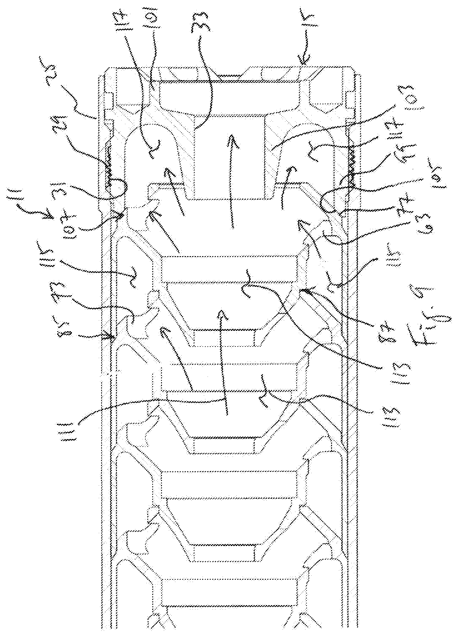
[0052] FIGS. 21 through 23 illustrate alternative embodiments of baffles having various modifications from baffles described above. The baffles of these embodiments are configured similarly to baffles described above, and the baffles are configured for use in a suppressor similar to suppressor 11 and to operate in the same manner. The discussion will be limited to these modifications while incorporating the above description.
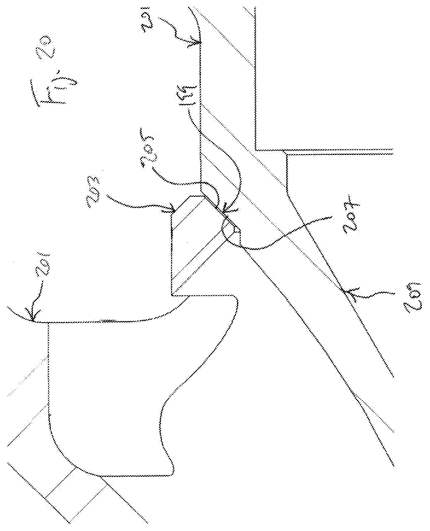
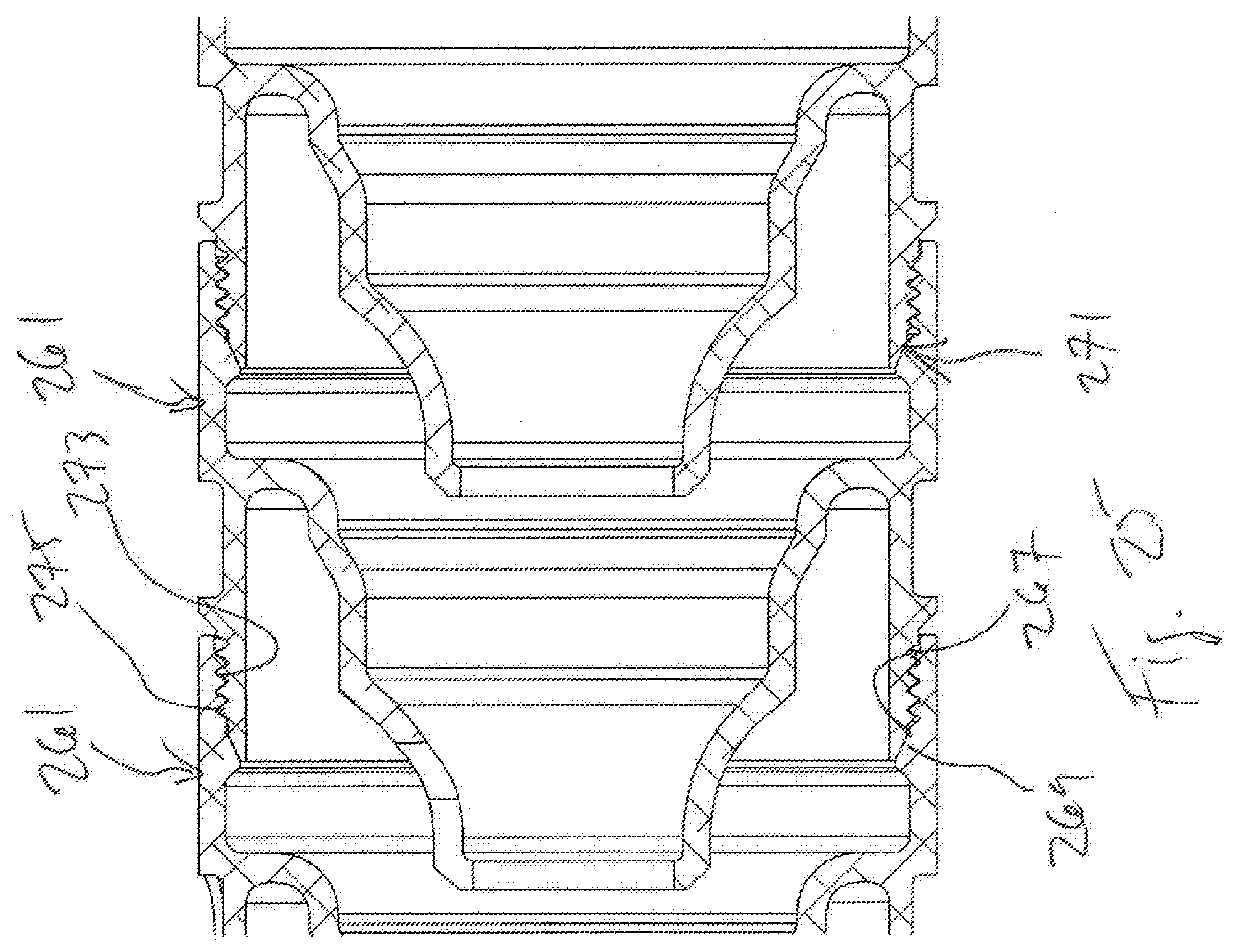
[0053] FIG. 21 illustrates two baffles 211 assembled into a stack. Like baffles described above, each baffle 211 has an outer wall 213, a central cone 215, and a chamber wall 217. Chamber wall 217 extends forward and inward from the forward end of outer wall 213 to form a frustum. However, chamber wall 217 differs from those described above by the addition of extension wall 219, which is an annular ring extending forward from the inner portion of chamber wall 217. Instead of the inner portion of chamber wall 217 mating with cone 215 of the forward adjacent baffle 211, the forward end of extension wall 219 mates with cone 215 in the same manner as described above for baffle 19. The addition of extension wall 219 increases the distance between cone 215 of forward baffle 211 and chamber wall 217 of rearward baffle 211, thereby increasing the volume of coaxial expansion chamber 221.
[0054] FIG. 22 illustrates two baffles 223 assembled into a stack. Like baffles described above, each baffle 223 has an outer wall 225, a central cone 227, and a chamber wall 229. Outer wall 225 of each baffle 223 has a forward tapered surface 231 and a rearward tapered surface 233, the taper angles of surfaces 231, 233 being equal to allow for surfaces 231, 233 to mate when baffles 223 are assembled, thereby forming a tapered seal 235 between outer walls 225 of adjacent baffles 223. To retain baffles 223 together in a stack, outer wall 225 of each baffle 223 has internal threads 237 formed on a rearward portion of outer wall 225 and external threads 239 formed on a forward portion of outer wall 225. When baffles 223 are assembled together, baffles 223 are rotated relative to each other engage threads 237, 239 for retaining baffles 223 together. Baffles 223 are rotated relative to each other to move baffles 223 toward each other, and this causes tapered surfaces 231, 233 to move toward each other until they mate, forming tapered seal 235. By threadingly retaining baffles 223 to each other and providing a tapered seal 235 between outer walls 225, this configuration eliminates the need for a tube to house baffles 223, though a tube can optionally be used. An advantage to a tubeless design is that the user can operate a firearm with more or fewer baffles based on the application and desired effect. Though not shown, it should be understood that threaded end caps will be installed to terminate the baffle stack, providing for enclosed front expansion chambers and for a feature to couple baffles 223 to a firearm. Also, in another embodiment the location of threads 237, 239 on baffle 223 can be reversed, so that external threads are formed at a rearward portion of baffle 223 and internal threads are formed at a forward portion of baffle 223.
[0055] FIG. 23 illustrates two baffles 241 assembled into a stack. Like baffles described above, each baffle 241 has an outer wall 243, a central cone 245, and a chamber wall 247. Outer wall 225 of each baffle 223 has a forward tapered surface 249 and a rearward tapered surface 251, the taper angles of surfaces 249, 251 being equal to allow for surfaces 249, 251 to mate when baffles 241 are assembled, thereby forming a tapered seal 253 between outer walls 243 of adjacent baffles 241. In this embodiment, cone 245 extends rearward from a rear portion of outer wall 243, and chamber wall 247 extends rearward from a central portion of cone 245. The outer end of chamber wall 247 has features like those described above for mating with features on inner surface 255 of outer wall 243 and forming a seal 257, thereby forming coaxial expansion chamber 259.
[0056] FIG. 24 illustrates baffle 261, which is another embodiment according to this disclosure, and FIG. 25 illustrates baffles 261 assembled into a stack. Each baffle 261 has an outer wall 263 and a central cone 265. Outer wall 263 of each baffle 261 has a forward tapered surface 267 and a rearward tapered surface 269, the taper angles of surfaces 267, 269 being equal to allow for surfaces 267, 269 to mate when baffles 261 are assembled, thereby forming a tapered seal 271 between outer walls 263 of adjacent baffles 261. To retain baffles 261 together in a stack, outer wall 263 of each baffle 261 has internal threads 273 formed on a forward portion of outer wall 263 and external threads 275 formed on a rearward portion of outer wall 263. When baffles 261 are assembled together, baffles 261 are rotated relative to each other to engage threads 273, 275 for retaining baffles 261 together. Baffles 261 are rotated relative to each other to move baffles 261 toward each other, and this causes tapered surfaces 267, 269 to move toward each other until they mate, forming tapered seal 271. By threadingly retaining baffles 261 to each other and providing a tapered seal 271 between outer walls 263, this configuration eliminates the need for a tube to house baffles 261, though a tube can optionally be used. Also, by having tapered seal 271 formed inside of threads 273, 275, seal 271 limits or eliminates the amount of gases and particulates that reach and collect within the interface of threads 273, 275.
[0057] Though not shown, it should be understood that threaded end caps will be installed to terminate the baffle stack, providing for enclosed front expansion chambers and for a feature to couple baffles 261 to a firearm. Also, in another embodiment the location of threads 273, 275 on baffle 261 can be reversed, so that external threads are formed at a forward portion of baffle 261 and internal threads are formed at a rearward portion of baffle 261. Likewise, the location and/or taper direction of tapered surfaces 267, 269 can be reversed. Though not shown with a chamber wall for creating a coaxial chamber, it should be understood that all appropriate features of the baffles described above may be incorporated into baffle 261.
[0058] The firearm suppressor of this disclosure provides several significant advantages, including: (1) providing central and coaxial expansion chambers; and (2) providing baffles and caps with tapered seals that prevent or minimize the amount of gas escaping between baffles and eliminate the need for cap O-rings.
[0059] At least one embodiment is disclosed, and variations, combinations, and/or modifications of the embodiment(s) and/or features of the embodiment(s) made by a person having ordinary skill in the art are within the scope of the disclosure. Alternative embodiments that result from combining, integrating, and/or omitting features of the embodiment(s) are also within the scope of the disclosure. Where numerical ranges or limitations are expressly stated, such express ranges or limitations should be understood to include iterative ranges or limitations of like magnitude falling within the expressly stated ranges or limitations (e.g., from about 1 to about 10 includes, 2, 3, 4, etc.; greater than 0.10 includes 0.11, 0.12, 0.13, etc.). For example, whenever a numerical range with a lower limit, R.sub.l, and an upper limit, R.sub.u, is disclosed, any number falling within the range is specifically disclosed. In particular, the following numbers within the range are specifically disclosed: R=R.sub.l+k*(R.sub.u-R.sub.l), wherein k is a variable ranging from 1 percent to 100 percent with a 1 percent increment, i.e., k is 1 percent, 2 percent, 3 percent, 4 percent, 5 percent, . . . 50 percent, 51 percent, 52 percent, . . . , 95 percent, 96 percent, 95 percent, 98 percent, 99 percent, or 100 percent. Moreover, any numerical range defined by two R numbers as defined in the above is also specifically disclosed. Use of the term "optionally" with respect to any element of a claim means that the element is required, or alternatively, the element is not required, both alternatives being within the scope of the claim. Use of broader terms such as comprises, includes, and having should be understood to provide support for narrower terms such as consisting of, consisting essentially of, and comprised substantially of. Accordingly, the scope of protection is not limited by the description set out above but is defined by the claims that follow, that scope including all equivalents of the subject matter of the claims. Each and every claim is incorporated as further disclosure into the specification and the claims are embodiment(s) of the present invention. Also, the phrases "at least one of A, B, and C" and "A and/or B and/or C" should each be interpreted to include only A, only B, only C, or any combination of A, B, and C.
* * * * *
D00000
D00001
D00002
D00003
D00004
D00005
D00006
D00007
D00008
D00009
D00010
D00011
D00012
D00013
D00014

D00015

D00016

D00017

D00018
D00019

D00020
D00021
D00022
D00023
XML
uspto.report is an independent third-party trademark research tool that is not affiliated, endorsed, or sponsored by the United States Patent and Trademark Office (USPTO) or any other governmental organization. The information provided by uspto.report is based on publicly available data at the time of writing and is intended for informational purposes only.
While we strive to provide accurate and up-to-date information, we do not guarantee the accuracy, completeness, reliability, or suitability of the information displayed on this site. The use of this site is at your own risk. Any reliance you place on such information is therefore strictly at your own risk.
All official trademark data, including owner information, should be verified by visiting the official USPTO website at www.uspto.gov. This site is not intended to replace professional legal advice and should not be used as a substitute for consulting with a legal professional who is knowledgeable about trademark law.