Adjustable Gas Block Assembly For A Gas Operated Semi-automatic Firearm
Williams; Charles David ; et al.
U.S. patent application number 16/191805 was filed with the patent office on 2020-01-23 for adjustable gas block assembly for a gas operated semi-automatic firearm. The applicant listed for this patent is Springfield, Inc.. Invention is credited to Christopher Martin Baumbach, Charles David Williams.
| Application Number | 20200025477 16/191805 |
| Document ID | / |
| Family ID | 69161039 |
| Filed Date | 2020-01-23 |


| United States Patent Application | 20200025477 |
| Kind Code | A1 |
| Williams; Charles David ; et al. | January 23, 2020 |
ADJUSTABLE GAS BLOCK ASSEMBLY FOR A GAS OPERATED SEMI-AUTOMATIC FIREARM
Abstract
Adjustable gas block assemblies for gas-operated firearms are disclosed along with modes of operation and methods of use. In certain aspects, gas blocks having a vent opening arranged to receive a vent plug are disclosed, the vent plug having an opening along a length thereof to vent high-pressure gas from the gas block. Kits containing multiple vent plugs and, in some instances, gas blocks are also disclosed.
| Inventors: | Williams; Charles David; (Geneseo, IL) ; Baumbach; Christopher Martin; (LeClaire, IA) | ||||||||||
| Applicant: |
|
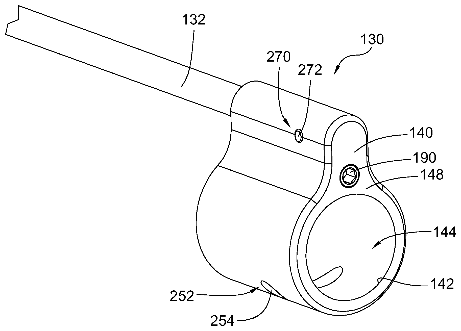
||||||||||
|---|---|---|---|---|---|---|---|---|---|---|---|
| Family ID: | 69161039 | ||||||||||
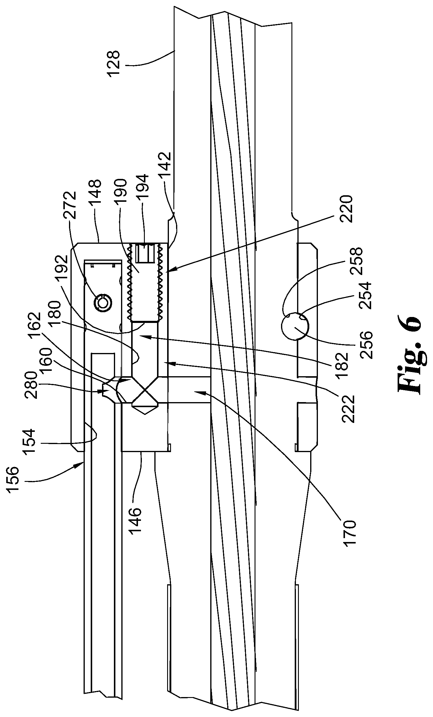
| Appl. No.: | 16/191805 | ||||||||||
| Filed: | November 15, 2018 |
Related U.S. Patent Documents
| Application Number | Filing Date | Patent Number | ||
|---|---|---|---|---|
| 62586554 | Nov 15, 2017 | |||
| Current U.S. Class: | 1/1 |
| Current CPC Class: | F41A 5/28 20130101; F41A 3/66 20130101 |
| International Class: | F41A 5/28 20060101 F41A005/28; F41A 3/66 20060101 F41A003/66 |
Claims
1. A method of tuning the gas block assembly of claim 4, comprising: firing a cartridge in the firearm with the gas block assembly having the vent plug, which is a first vent plug, positioned within the vent opening; determining whether the firearm properly extracted and ejected the cartridge and chambered a new cartridge or locked a bolt of the firearm in an open configuration; replacing the first vent plug of the gas block assembly with a second vent plug having an opening extending along a length thereof, wherein the opening of the first vent plug has a different hydraulic diameter than the opening of the second vent plug; and firing a cartridge in the firearm with the gas block assembly having the second vent plug positioned within the vent opening.
2. The method of claim 1, wherein the opening of the second vent plug has a smaller hydraulic diameter than the opening of the first vent plug.
3. The method of claim 1, wherein the opening of the second vent plug has a larger hydraulic diameter than the opening of the first vent plug.
4. A gas block assembly for a firearm, comprising: a gas block defining a barrel opening, a gas tube opening, a passageway extending from the barrel opening to the gas tube opening, and a vent opening intersecting the passageway; and a vent plug received within the vent opening; wherein the vent plug has an opening extending along a length of the vent plug and in communication with the passageway so that high-pressure gas communicating with the passageway can pass through the opening in the vent plug and out of the gas block assembly.
5. The gas block assembly of claim 4, wherein the vent plug is removably received within the vent opening.
6. The gas block assembly of claim 4, wherein the vent plug is threadably received within the vent opening.
7. The gas block assembly of claim 4, wherein the vent opening is positioned between the gas tube opening and the barrel opening.
8. The gas block assembly of claim 4, wherein the vent opening extends from a forward surface of the gas block rearward to the passageway and wherein the gas tube opening extends from a rearward surface of the gas block forwardly to the passageway.
9. The gas block assembly of claim 4, wherein the vent plug has a length sufficient to extend at least partially into the passageway when received within the vent opening.
10. The gas block assembly of claim 4, wherein the vent opening has a first cross-sectional dimension adjacent an outer surface of the gas block and a second cross-sectional dimension adjacent the passageway and intermediate the passageway and the first cross-sectional dimension; and wherein the second cross-sectional dimension is smaller than the first cross-sectional dimension.
11. The gas block assembly of claim 10, wherein the vent plug has a first end matching the first cross-sectional dimension and a second end matching the second cross-sectional dimension.
12. The gas block assembly of claim 10, wherein a portion of the vent opening having the first cross-sectional dimension of the vent opening is a threaded portion and a portion of the vent opening having the second cross-sectional dimension is free of threads.
13. An upper assembly for a firearm, comprising: the gas block assembly of claim 4; an upper receiver; and a barrel attached to the upper receiver; wherein the gas block assembly is attached to the barrel.
14. A firearm, comprising: the upper assembly of claim 13 attached to a lower assembly.
15. A kit, comprising: the gas block assembly of claim 4 wherein the vent plug is a first vent plug; and a second vent plug for the gas block; wherein the second vent plug has a length.
16. The kit of claim 15, wherein: the opening of the first vent plug has a minimum cross-sectional dimension; and the second vent plug has an orifice extending through the length thereof, the orifice of the second vent plug having a minimum cross-sectional dimension less than that of the orifice opening of the first vent plug.
17. The kit of claim 15, wherein: the second vent plug is free of an orifice extending through the length thereof.
18. The kit of claim 15, wherein: the length of one of the first or second vent plugs is greater than the other
19. The kit of claim 18, wherein: the longer vent plug is free of an orifice.
20. (canceled)
Description
REFERENCE TO RELATED APPLICATIONS
[0001] The present application claims the benefit of U.S. Provisional Patent Application No. 62/586,554, filed Nov. 15, 2017, which is incorporated by reference herein.
FIELD OF THE INVENTION
[0002] The present disclosure pertains generally to gas operated firearms. In particular, the present disclosure pertains to rifles or pistols having a direct impingement or a gas piston system.
BACKGROUND
[0003] Firearms are very often "chambered" for a particular caliber, but some firearms are designed to operate (e.g., cycle) with multiple calibers of ammunition, without causing damage to the firearm. For example, AR-15 rifles are presently chambered in 5.56x45 NATO, .223 Remington/Wylde, .308 Winchester, or .300 Blackout, just to name a few non-limiting examples. Many AR-15 rifles chambered in 5.56x45 NATO can operate using both 5.56x45 NATO and 0.223 Remington.
[0004] Different calibers of ammunition often have different size projectiles and/or different powder charges. Ammunition of the same caliber can even vary in terms of projectile size and powder charge. For example, projectiles are often provided in full-metal jacket (FMJ) or jacketed hollow point (JHP) and can be found in different sizes (e.g., grain). Additionally, manufacturers may use different quantities and/or types of propellant (i.e., powder) in their cartridges, which can result in ammunition having different pressure profiles (e.g., higher maximum pressure) inside the barrel than another manufacturer's ammunition. This can be due, at least in part, to the burn rate of the propellant.
[0005] In a gas-operated firearm, a portion of the high-pressure gas that propels the projectile down the barrel also provides energy to extract a spent cartridge and to load a new cartridge into the chamber. In many systems, gas is channeled from a gas port in the wall of the barrel to a piston and/or through a gas tube directly to the action of the firearm to move the bolt away from the barrel chamber. In many instances, a gas block connects the gas tube to the gas port.
[0006] As may be expected, firearms can operate differently depending on the caliber and/or ammunition being used. In instances wherein the energy of the high-pressure gas supplied through the gas port is significantly more than that necessary to extract a spent cartridge and load a new cartridge in the chamber, the firearm may cycle more violently than designed. This can be uncomfortable to a shooter and, in some instances, may damage the firearm. In other instances, the energy of the gas supplied through the gas port is less than that necessary to cycle the firearm, which may result in the firearm failing to extract a spent cartridge, load a new cartridge into the chamber, and/or lock the bolt in an open configuration (e.g., to the rear).
[0007] Adjustable gas blocks such as U.S. Publication No. 2014/0076149 to Adams reduce the volume of gas flowing through the gas block to the gas tube. Gas blocks of this type, however, can be difficult and/or time consuming to tune when switching firearm configurations (e.g., ammunition, muzzle brakes, suppressed/unsuppressed arrangements, etc.).
SUMMARY
[0008] The present disclosure pertains generally to gas operated firearms. In particular, the present disclosure pertains to rifles or pistols having a direct impingement or a gas piston system. Specifically, the firearms disclosed herein can be AR style firearms (e.g., AR-15, AR-10, M-16, and M-4), and any of the methods, assemblies or kits disclosed herein can be used with an AR style firearm.
[0009] In one exemplary method of tuning an adjustable gas block assembly of a firearm, the method comprises: firing a cartridge in the firearm with the gas block assembly having a first vent plug positioned within a vent opening; determining whether the firearm properly extracted and ejected the cartridge and chambered a new cartridge or locked a bolt of the firearm in an open configuration; replacing the first vent plug of the gas block assembly, the first vent plug having an opening extending along a length thereof, with a second vent plug having an opening extending along a length thereof, wherein the opening of the first vent plug has a different hydraulic diameter than the opening of the second vent plug; and firing a cartridge in the firearm with the gas block assembly having the second vent plug positioned within the vent opening. The opening of the second vent plug can have a smaller hydraulic diameter than the opening of the first vent plug or, alternatively, the opening of the second vent plug can have a larger hydraulic diameter than the opening of the first vent plug.
[0010] In an exemplary gas block assembly of the present disclosure, the gas block assembly comprises: a gas block defining a barrel opening, a gas tube opening, a passageway extending from the barrel opening to the gas tube opening, and a vent opening intersecting the passageway; and a vent plug received within the vent opening; wherein the vent plug has an opening extending along a length of the vent plug and in communication with the passageway so that high-pressure gas communicating with the passageway can pass through the opening in the vent plug and out of the gas block assembly. The vent plug can be removably received within the vent opening, and the vent plug can be threadably received within the vent opening.
[0011] The present disclosure also provides upper assemblies for a firearm, the upper assembly comprising: any one of the gas block assemblies disclosed herein; an upper receiver; and a barrel attached to the upper receiver; wherein the gas block assembly is attached to the barrel. The present disclosure also provides firearms, comprising: the upper assembly previously mentioned attached to a lower assembly.
[0012] Kits containing vent plugs are also disclosed. These kits may include a first vent plug for a gas block and a second vent plug for the gas block; wherein the first and second vent plugs each have a length and at least one of the first and second vent plugs has an orifice extending through the length thereof. The first vent plug can have an orifice extending through the length thereof, the orifice having a minimum cross-sectional dimension; and the second vent plug can have an orifice extending through the length thereof, the orifice of the second vent plug having a minimum cross-sectional dimension less than that of the orifice of the first vent plug. Alternatively, the first vent plug can have an orifice extending through the length thereof and the second vent plug can be free of an orifice extending through the length thereof. In any of the kits, the length of one of the first or second vent plugs can be greater than the other. The kits may also include a gas block having a vent opening arranged to receive the first or second vent plugs. A gas tube, one or more setscrews, and/or thread-locking liquid may be provided in any of the kits disclosed herein.
[0013] Further forms, objects, features, aspects, benefits, advantages, and embodiments of the present invention will become apparent from a detailed description and drawings provided herewith.
BRIEF DESCRIPTION OF THE DRAWINGS
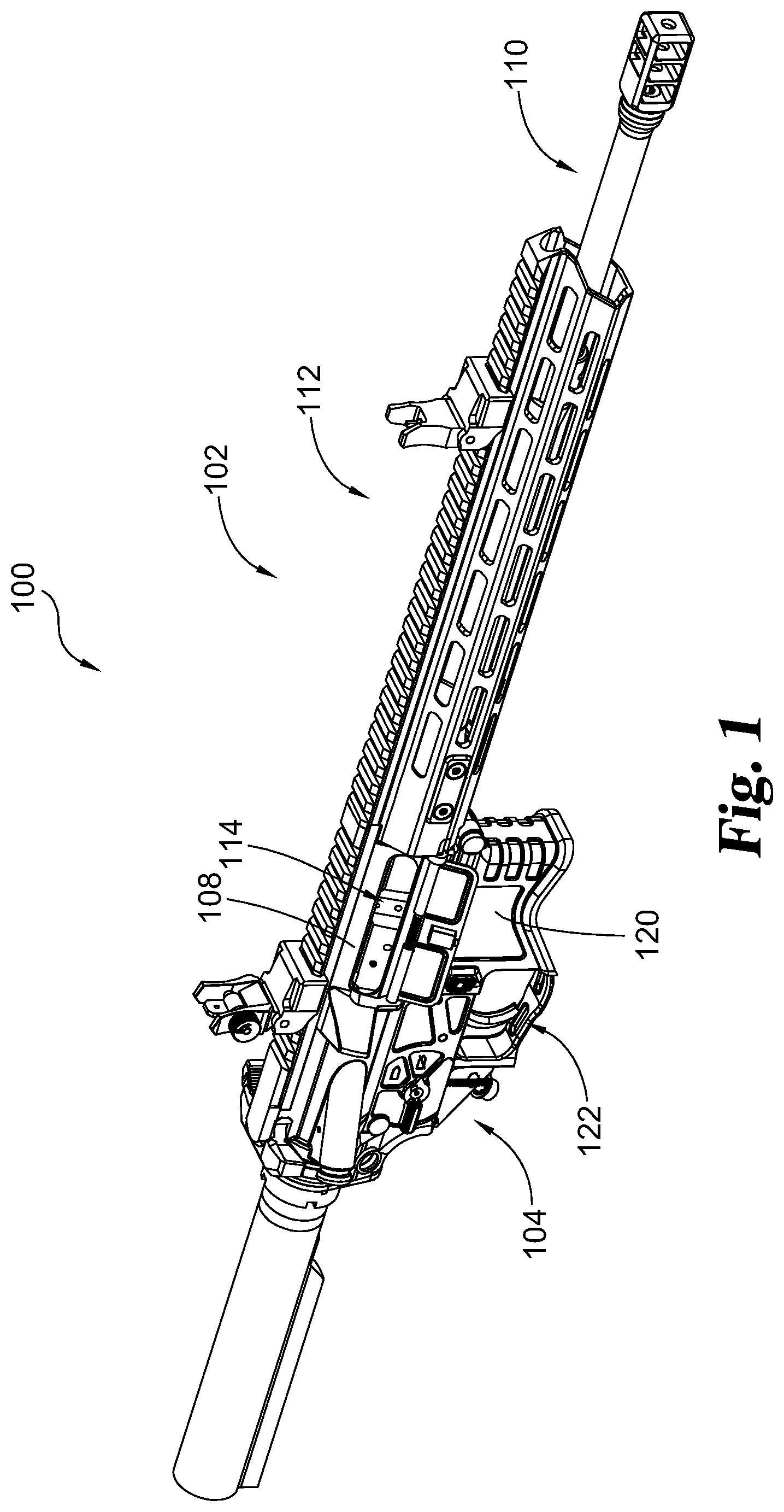
[0014] FIG. 1 is a perspective view of a firearm;
[0015] FIG. 2 is a perspective view of the firearm of FIG. 1 with the handguard, front sight, and barrel attachment device removed;
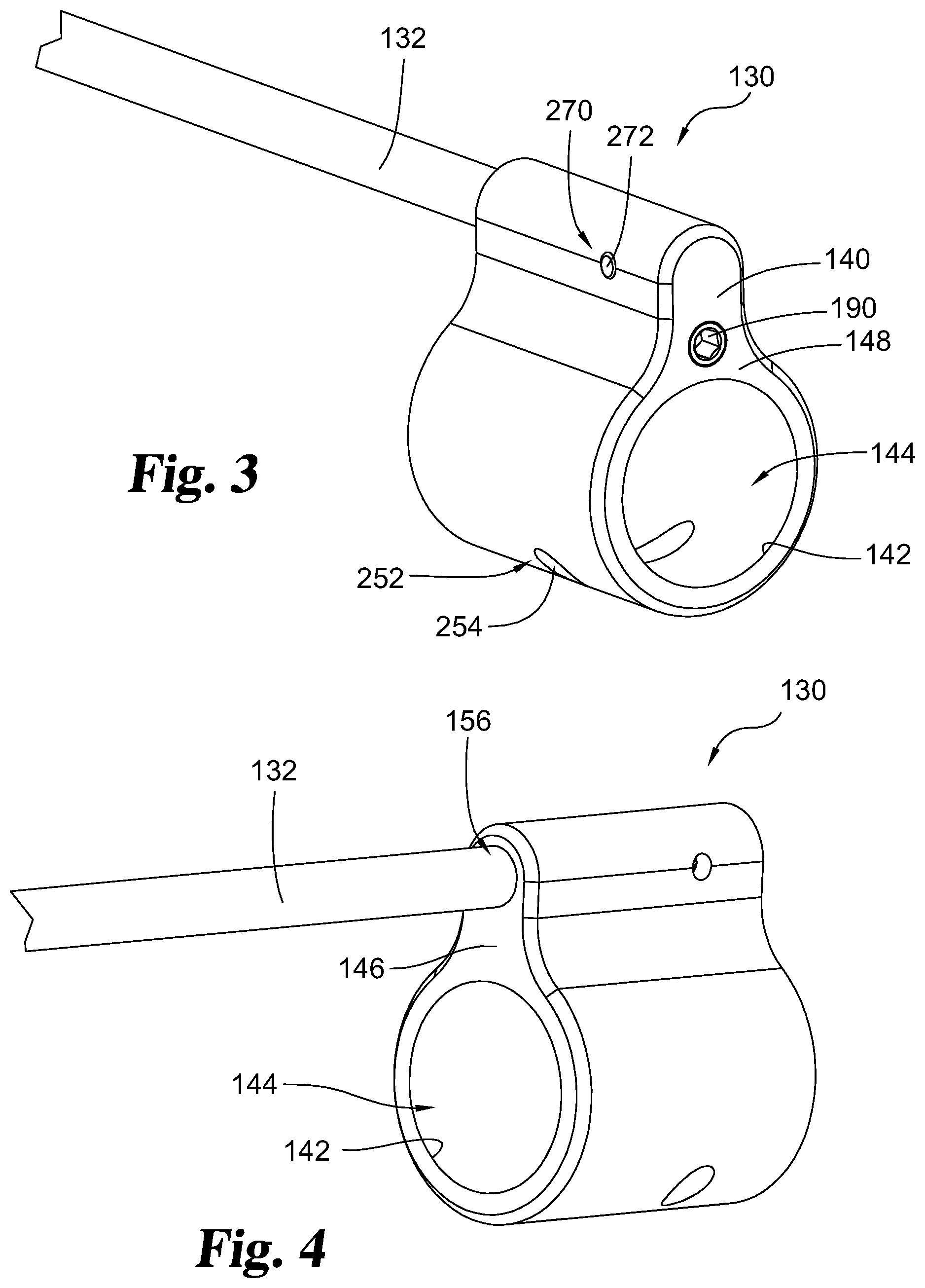
[0016] FIG. 3 is a perspective view of a gas block assembly and a gas tube;
[0017] FIG. 4 is a perspective view of the gas block assembly and gas tube of FIG. 3;
[0018] FIG. 5 is an exploded view of the gas block assembly of FIG. 3;
[0019] FIG. 6 is a cross-sectional view of the gas block assembly on a barrel;
[0020] FIGS. 7A-7E are cross-sectional views of vent plugs;
[0021] FIG. 8 is a cross-sectional view of a gas block assembly on a barrel with a portion of a vent plug blocking the passageway of the gas block extending between the gas port and the gas tube; and
[0022] FIGS. 9-11 are flowcharts illustrating methods of use.
DESCRIPTION OF THE SELECTED EMBODIMENTS
[0023] For the purpose of promoting an understanding of the principles of the invention, reference will now be made to the embodiments illustrated in the drawings and specific language will be used to describe the same. It will nevertheless be understood that no limitation of the scope of the invention is thereby intended. Any alterations and further modifications in the described embodiments, and any further applications of the principles of the invention as described herein are contemplated as would normally occur to one skilled in the art to which the invention relates. One embodiment of the invention is shown in great detail, although it will be apparent to those skilled in the relevant art that some features that are not relevant to the present invention may not be shown for the sake of clarity.
[0024] FIG. 1 illustrates an exemplary rifle 100 of the present disclosure. The rifle includes in upper assembly 102 and a lower assembly 104. The upper assembly includes an upper receiver 108, a barrel assembly 110, a handguard assembly 112, and a bolt carrier group 114. The lower assembly includes a lower receiver 120, and a trigger assembly 122.
[0025] As shown in FIG. 2, the barrel assembly includes a barrel 128, a gas block assembly 130 and a gas tube 132 or a gas piston that extends rearward from the gas block to the bolt carrier group of the upper assembly. In direct impingement systems having a gas tube, the rearward end of the gas tube fits inside of a gas key mounted at the top of the bolt carrier group so that high-pressure gas inside of the gas tube directly impinges the bolt carrier group.
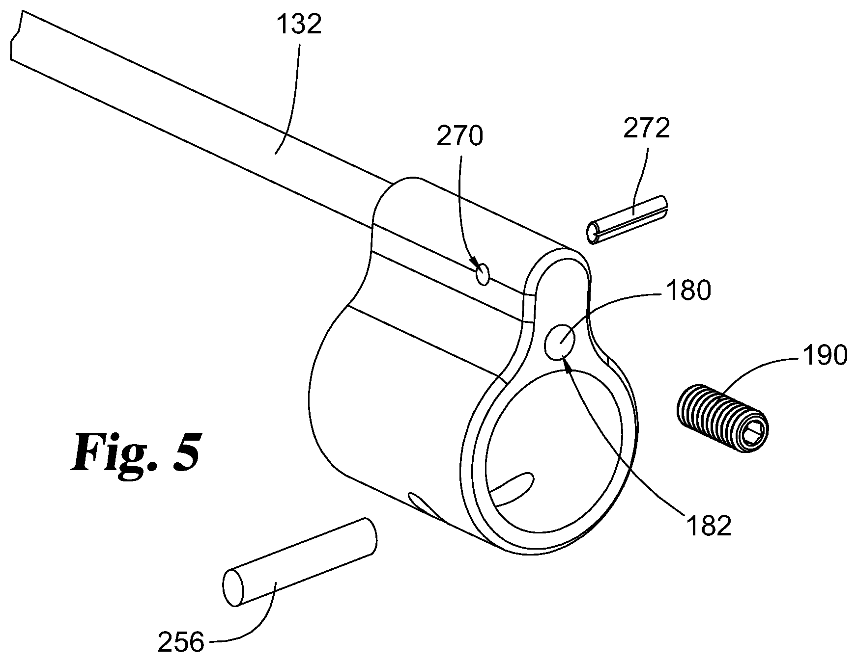
[0026] The gas block assembly includes a gas block 140 and one or more vent plugs 190. The gas block has a first interior surface 142 defining a barrel opening 144 for the receiving the barrel. The barrel opening extends between a rearward surface 146 and a forward surface 148 of the gas block.
[0027] The gas block has a second interior surface 154 defining a gas tube opening 156 for receiving the gas tube. The gas tube opening extends forwardly from the rearward surface of the gas block. The gas tube opening may extend only partially through the gas block or it may extend completely through the gas block.
[0028] The gas block has a third interior surface 160 defining a passageway 162 extending transverse to and between the barrel opening and the gas tube opening. The passageway communicates with a gas port 170 of the barrel so that high-pressure gas from the barrel may travel from the gas port, into the passageway 162 and towards the gas tube opening.
[0029] The gas block has a fourth interior surface 180 defining a vent opening 182. The vent opening intersects the passageway 162 between the barrel opening and the gas tube opening. The vent opening is arranged to receive a vent plug 190. For example, the fourth interior surface may have a threaded portion for threadably receiving the vent plug. The vent opening can extend in a forward direction from the passageway so as to open on the forward surface of the gas block.
[0030] The vent plug may be a removable plug. The vent plug can be sized and arranged so as to block a portion of the vent opening. For example, the vent plug may be arranged to fill a cross-sectional area of the vent opening.
[0031] The vent plug can have a self-locking portion to secure the plug to the gas block. For example, the vent plug may be formed of a first material (e.g., metal) and include a locking, second material (e.g., a polymeric material) to increase the frictional resistance between the vent plug and the gas block.
[0032] FIGS. 7A to 7E illustrate embodiments of vent plugs. The vent plug may be free of an opening extending along a length of the vent plug, or, alternatively, the vent plug may have an internal surface 192 defining an opening 194 that extends along a length of the plug. For example, the vent plug may have an opening that extends from a rearward surface 196 to a forward surface 198. The opening can have a portion extending linearly through the vent plug.
[0033] The opening in the vent plug in the plug is arranged to vent high-pressure gas out of the firearm. Advantageously, such an arrangement can reduce the gas pressure delivered through the gas block into the gas tube and, consequently, to the action of the firearm. Additionally, Applicant has found that venting high-pressure gas out of the gas block can reduce carbon fouling over time. Moreover, venting high-pressure gas out of the gas block can reduce the risk of gas leakage at the interface between the gas block and the barrel.
[0034] Vent plugs may have openings of different sizes and/or shapes. For example, a vent plug may have an opening having a hydraulic diameter that is larger than a hydraulic diameter of another plug. Similarly, a vent plug may have an opening with a cross-sectional shape different from another vent plug (the cross-sectional shape being determined either in a plane orthogonal or parallel to a longitudinal axis of the vent plug).
[0035] The vent plug can be arranged to selectively block portions of the passageway of the gas block. As shown in FIG. 8, such an arrangement can restrict the amount of gas that passes through the gas block into the gas tube. For example, the plug may operate as a valve (e.g., needle valve or ball valve) that can be operated to increase and/or decrease the hydraulic diameter of a portion of the passageway. FIGS. 7B and 7E illustrate embodiments wherein the vent plug has a length sufficient to extend to the passageway in the gas block when positioned in the vent opening. In at least such instances, the vent plug may have a first length 210 with external threads and a second length 212 free of external threads, with the second length arranged to extend, at least partially, into the passageway of the gas block.
[0036] Vent plugs may be provided in various lengths and/or with indicia that index to the gas block. For example, vent plugs may be provided in various lengths arranged to block predetermined amounts (e.g., 10%, 20%, 30%, 40%, or 50%) of the passageway when the forward end of the vent plug is flush with the forward surface of the gas block. Alternatively, or additionally, vent plugs may have indicia along a portion of the vent plug (e.g., along a length thereof or radially around the vent plug) corresponding to the extent the passageway is blocked when the marking is indexed to a corresponding indicia or surface of the gas block. For example, a vent plug may have a first indicia that corresponds to a tuned configuration for a first ammunition and a second indicia that corresponds to a tuned configuration for a second ammunition.
[0037] The vent opening may vary in cross-sectional dimension (e.g., hydraulic diameter) along the length thereof. For example, a first length 220 of the vent opening proximal an outer surface of the gas block may have a larger maximum cross-sectional dimension than a second length 222 of the vent opening adjacent the passageway. The vent plug(s) may have a corresponding shape.
[0038] Kits containing one or more vent plugs are envisioned. For example, kits can contain a plurality of vent plugs having different vent plug lengths and/or openings of different sizes for venting high-pressure gas. Additionally or alternatively, kits may contain a vent plug without an opening and a vent plug with an opening for venting high-pressure gas. Kits having one or more vent plugs may include the gas block and/or the gas tube.
[0039] The gas block may include a barrel pin opening 252 defined by a barrel pin surface 254 extends transverse to the barrel opening. When a barrel is positioned within the barrel opening of the gas block, a barrel pin 256 may be inserted between a pin surface 258 of the barrel and the barrel pin surface 254 of the gas block. Advantageously, the pin can resist rotation and/or lateral movement of the gas block relative to the barrel so as to maintain alignment of the passageway of the gas block with the gas port of the barrel.
[0040] The gas block may include one or more openings to receive setscrews for securing the gas block to the barrel. Such setscrews may be included with any of the kits or assemblies described herein.
[0041] Extending transverse to the gas tube opening is a gas tube pin opening 270 for receiving a gas tube pin 272. The gas tube pin serves to secure the gas tube in the gas tube opening with a port 280 of the gas tube aligned with the passageway of the gas block.
[0042] Any of the above-described embodiments may be provided as a kit or assembled on a portion of a firearm. For example, the gas block assemblies described herein may be provided on barrels, including barrels attached to upper receivers, or barrels of completed firearms.
MODES OF OPERATION
[0043] Advantageously, the gas block assemblies described herein can be operated in different modes, as may be selected by the operator. In a first mode, the gas block may have a vent plug blocking the vent opening without venting high-pressure gas out of the gas block or blocking a portion of the passageway.
[0044] In a second mode, a ported vent plug (e.g., a vent plug with an opening that allows the passage of high-pressure gas) may be positioned in the vent opening. In the second mode, a vent plug may be selected based on opening (e.g., orifice) size. As mentioned above, the opening is arranged to vent high-pressure gas out of the gas block so less pressure and/or gas volume reaches the gas tube or gas piston.
[0045] In a third mode of operation, a vent plug having a portion blocking a portion of the passageway is positioned in the vent opening. The vent plug can be selectively positioned to limit the gas pressure and/or volume that passes through the gas block and to the gas tube or gas piston.
[0046] In a fourth mode of operation, the vent plug both blocks a portion of the passageway and has an opening to vent high-pressure gas out of the gas block.
Methods of Use
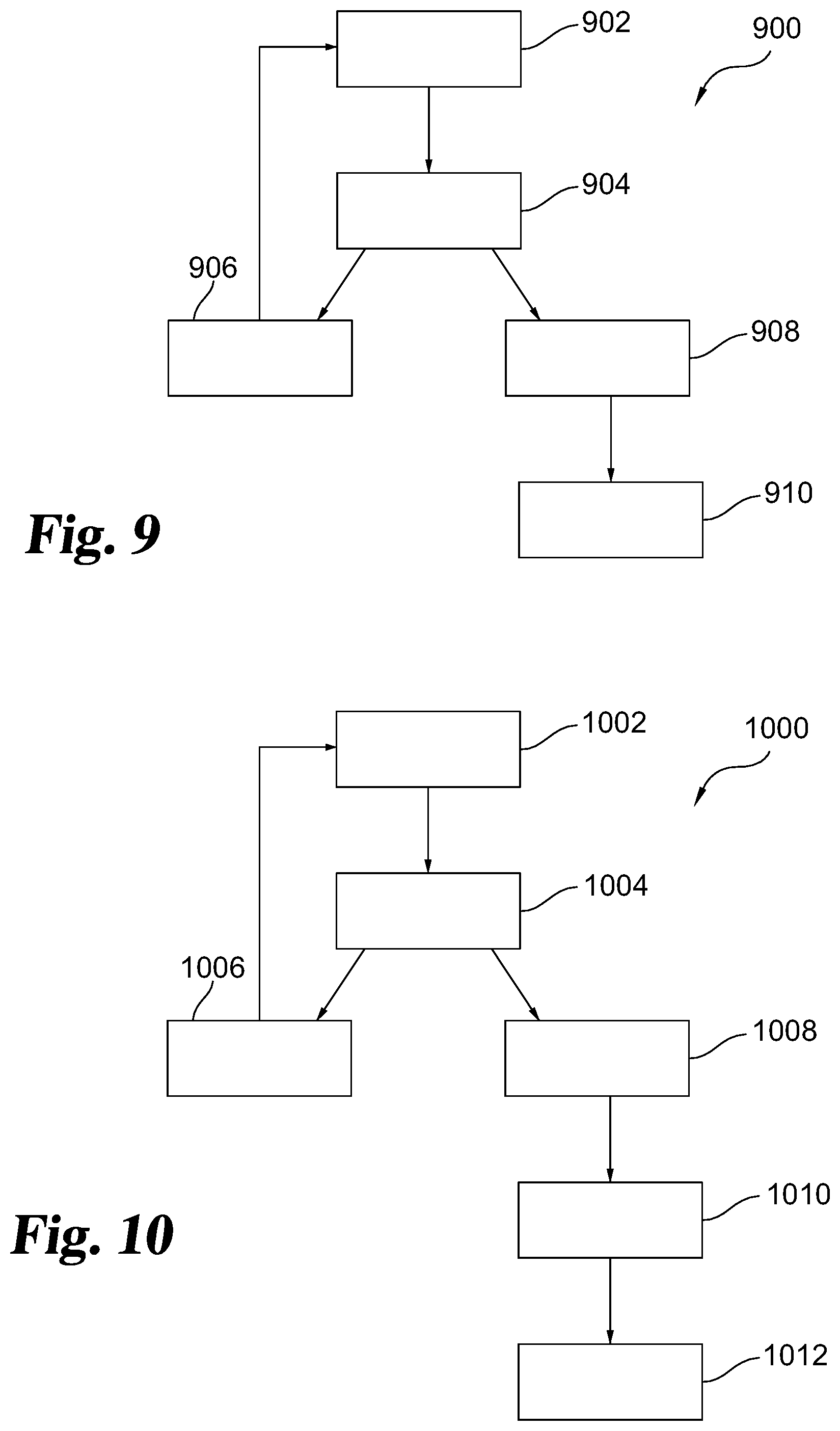
[0047] A method of using the gas block assembly in the second mode, discussed above, will now be discussed with reference to FIG. 9. In stage 902 of method 900, an operator shoots the firearm with a ported vent plug (i.e., a vent plug with an opening) in the vent opening. The operator then inspects, stage 904, whether the firearm properly extracted and ejected the spent cartridge and locked the bolt to the rear after the last shot fired (e.g., from a magazine or clip). If the firearm failed to extract and eject the spent cartridge and lock the bolt to the rear after the last shot fired, then the operator replaces the vent plug with one having a smaller opening, stage 906. The operator will repeat this process (i.e., shooting and inspecting whether the firearm properly extracted and ejected the spent cartridge and locked the bolt to the rear after the last shot). Once the firearm successfully extracts, ejects, and locks the bolt to the rear after the last shot, the gas block is considered tuned for that configuration (ammunition, suppressor, etc.). To ensure proper operation, the shooter should fire several test shots, in stage 908, to confirm proper operation. Finally, an operator may lock the vent plug in position in the vent opening, such as by using a setscrew and/or a thread-locking fluid in stage 910.
[0048] In tuning the second mode, it is preferable that the operator start with a vent plug having a large opening and then work progressively to vent plugs with smaller openings. However, it is envisioned that an operator may start with a vent plug with a small opening (or no opening) and then move to vent plugs with larger openings, as shown in method 1000 of FIG. 10. In this "reverse" procedure, an operator shoots the firearm with a vent plug in the vent opening, in stage 1002. The operator then inspects, stage 1004, whether the firearm properly extracted and ejected the spent cartridge and locked the bolt to the rear after the last shot fired (e.g., from a magazine or clip). If the firearm properly extracted and ejected the spent cartridge and locked the bolt to the rear, the operator may replace the vent plug with one having a larger opening, stage 1006, and repeat the process to determine whether the firearm functions properly with the larger-opening vent plug. The operator will repeat this process (i.e., shooting and inspecting whether the firearm properly extracted and ejected the spent cartridge and locked the bolt to the rear after the last shot). Once the firearm fails to successfully extract, eject, and lock the bolt to the rear after the last shot, the vent opening will be considered too large. The operator will then replace the vent plug with one having a smaller opening, stage 1008, and fire one or more additional test shots to ensure proper operation of the firearm in stage 1010. Finally, an operator may lock the vent plug in position in the vent opening, such as by using a setscrew and/or a thread-locking fluid in stage 1012.
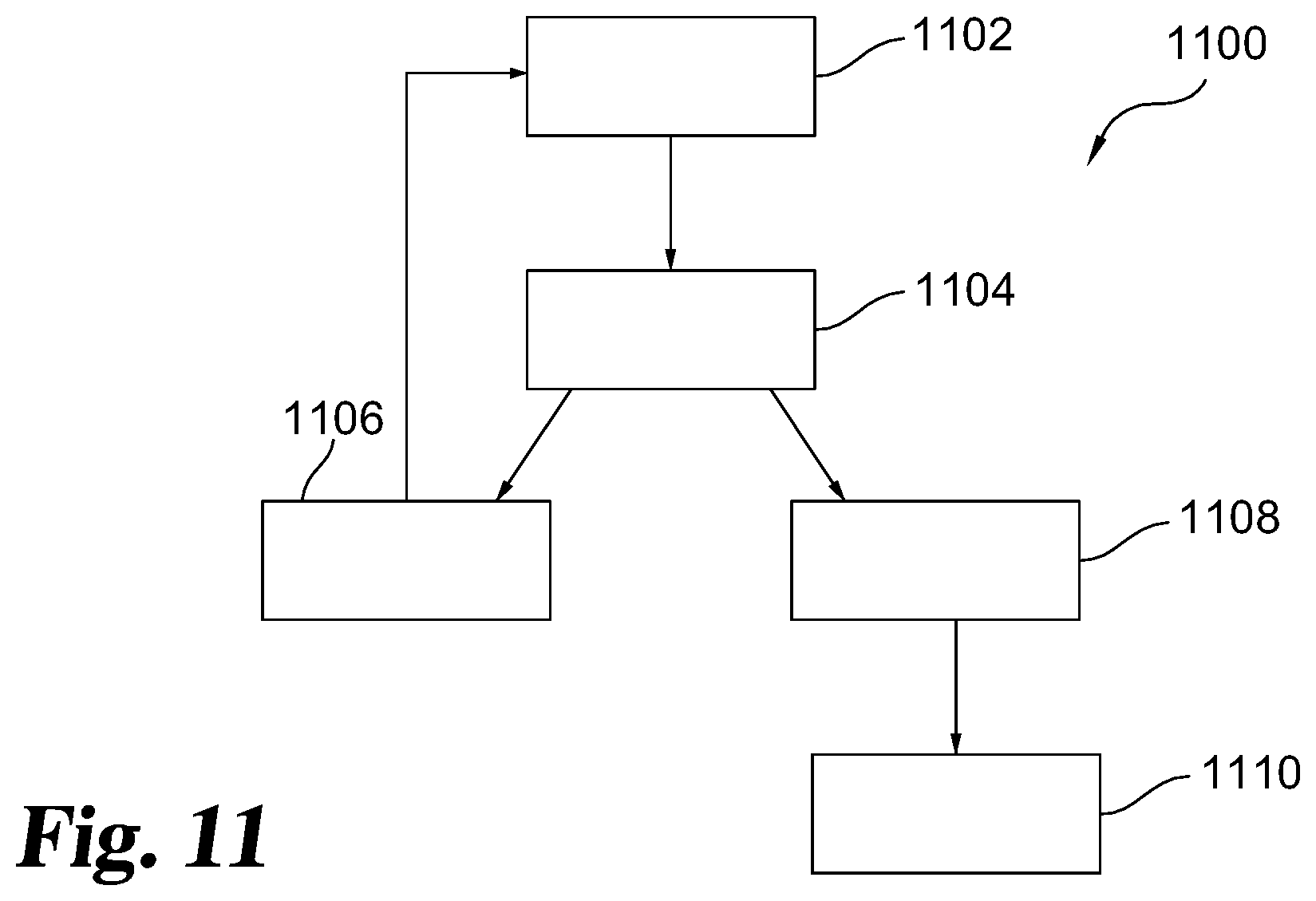
[0049] In a method 1100 of tuning the third mode, the operator shoots the firearm with the vent plug positioned in the vent opening and at least partially blocking the vent passageway (i.e., stage 1102). The shooter then inspects whether the firearm properly extracted and ejected the spent cartridge and locked the bolt to the rear after the last shot fired (e.g., from a magazine or clip) in stage 1104. If the firearm failed to extract and eject the spent cartridge and lock the bolt to the rear after the last shot fired, then the operator backs the vent plug out (i.e., out of the passageway) slightly (e.g., 1/4 turn or 1/2 turn) in stage 1106 and repeats the process. Once the firearm properly extracts and ejects the spent cartridge and locks the bolt to the rear, the operator may unscrew the vent plug an additional amount (e.g., an additional 1/4 turn) in stage 1108 to accommodate for minor variability (e.g., temperature, air pressure, etc.). If desired, the operator may lock the vent plug in position in the vent opening, such as by using a setscrew and/or a thread-locking fluid in stage 1110.
[0050] The method of tuning the third mode may also be performed in reverse (i.e., gradually increasing the amount the vent plug blocks the passageway) until the firearm ceases to function properly. The vent plug may then be backed out a desired amount and the firearm tested to confirm proper operation. As with the other methods disclosed, once proper operation of the firearm is achieved, the operator may lock the vent plug in position in the vent opening, such as by using a setscrew and/or a thread-locking fluid.
[0051] The above methods can be performed before, during, and/or after changes to the firearm's configuration. For example, one or more of the above methods may be performed on the firearm before and/or after a suppressor has been attached to the end of the barrel.
[0052] When switching between different firearm configurations (e.g., ammunition types, brands, or "loads", suppressed or not suppressed, etc.), an operator may simply swap the vent plug in the gas block with one tuned for that configuration. For example, when switching from shooting the firearm without a suppressor to shooting the firearm with a suppressor, an operator may replace the vent plug with one having a larger opening. Similarly, an operator switching between different types of ammunition (e.g., high-power ammunition to subsonic) may simply replace the vent plug with one tuned for the new ammunition.
[0053] Once an operator has found a vent plug configuration (e.g., vent plug length, opening size and/or positioning in the gas block) for a particular firearm configuration, an operator will be able to quickly switch between those firearm configurations and "re-tune" the gas block without having to repeat the experimental process initially used to identify the appropriate vent plug. The operator may record the vent plug(s) and/or vent plug positioning in the vent opening for a particular firearm configuration so that the gas block assembly can be configured for that configuration without further experimentation.
[0054] The following numbered clauses set out specific embodiments that may be useful in understanding the present invention:
[0055] 1. A method of tuning an adjustable gas block assembly of a firearm, comprising: firing a cartridge in the firearm with the gas block assembly having a first vent plug positioned within a vent opening;
[0056] determining whether the firearm properly extracted and ejected the cartridge and chambered a new cartridge or locked a bolt of the firearm in an open configuration;
[0057] replacing the first vent plug of the gas block assembly, the first vent plug having an opening extending along a length thereof, with a second vent plug having an opening extending along a length thereof, wherein the opening of the first vent plug has a different hydraulic diameter than the opening of the second vent plug; and
[0058] firing a cartridge in the firearm with the gas block assembly having the second vent plug positioned within the vent opening.
[0059] 2. The method of clause 1, wherein the opening of the second vent plug has a smaller hydraulic diameter than the opening of the first vent plug.
[0060] 3. The method of clause 1, wherein the opening of the second vent plug has a larger hydraulic diameter than the opening of the first vent plug.
[0061] 4. A gas block assembly for a firearm, comprising:
[0062] a gas block defining a barrel opening, a gas tube opening, a passageway extending from the barrel opening to the gas tube opening, and a vent opening intersecting the passageway; and
[0063] a vent plug received within the vent opening;
[0064] wherein the vent plug has an opening extending along a length of the vent plug and in communication with the passageway so that high-pressure gas communicating with the passageway can pass through the opening in the vent plug and out of the gas block assembly.
[0065] 5. The gas block assembly of clause 4, wherein the vent plug is removably received within the vent opening.
[0066] 6. The gas block assembly of clause 4 or 5, wherein the vent plug is threadably received within the vent opening.
[0067] 7. The gas block assembly of any one of clauses 4-6, wherein the vent opening is positioned between the gas tube opening and the barrel opening.
[0068] 8. The gas block assembly of any one of clauses 4-7, wherein the vent opening extends from a forward surface of the gas block rearward to the passageway and wherein the gas tube opening extends from a rearward surface of the gas block forwardly to the passageway.
[0069] 9. The gas block assembly of any one of clauses 4-8, wherein the vent plug has a length sufficient to extend at least partially into the passageway when received within the vent opening.
[0070] 10. The gas block assembly of any one of clauses 4-9, wherein the vent opening has a first cross-sectional dimension adjacent an outer surface of the gas block and a second cross-sectional dimension adjacent the passageway and intermediate the passageway and the first cross-sectional dimension; and
[0071] wherein the second cross-sectional dimension is smaller than the first cross-sectional dimension.
[0072] 11. The gas block assembly of clause 9, wherein the vent plug has a first end matching the first cross-sectional dimension and a second end matching the second cross-sectional dimension.
[0073] 12. The gas block assembly of clause 10 or 11, wherein the first cross-sectional dimension portion of the vent opening is a threaded portion and the second cross-sectional dimension portion is free of threads.
[0074] 13. An upper assembly for a firearm, comprising:
[0075] the gas block assembly of any one of the preceding clauses;
[0076] an upper receiver; and
[0077] a barrel attached to the upper receiver;
[0078] wherein the gas block assembly is attached to the barrel.
[0079] 14. A firearm, comprising:
[0080] the upper assembly of clause 13 attached to a lower assembly.
[0081] 15. A kit, comprising:
[0082] a first vent plug for a gas block and a second vent plug for the gas block;
[0083] wherein the first and second vent plugs each have a length and at least one of the first and second vent plugs has an orifice extending through the length thereof.
[0084] 16. The kit of clause 15, wherein:
[0085] the first vent plug has an orifice extending through the length thereof, the orifice having a minimum cross-sectional dimension; and
[0086] the second vent plug has an orifice extending through the length thereof, the orifice of the second vent plug having a minimum cross-sectional dimension less than that of the orifice of the first vent plug.
[0087] 17. The kit of clause 15, wherein:
[0088] the first vent plug has an orifice extending through the length thereof and the second vent plug is free of an orifice extending through the length thereof.
[0089] 18. The kit of any one of clauses 15-17, wherein:
[0090] the length of one of the first or second vent plugs is greater than the other
[0091] 19. The kit of clause 18 as dependent from clause 15 or clause 17, wherein:
[0092] the longer vent plug is free of an orifice.
[0093] 20. The kit of any one of clauses 14-19, comprising:
[0094] a gas block having a vent opening arranged to receive at least one of the first and second vent plugs.
[0095] While the invention has been illustrated and described in detail in the drawings and foregoing description, the same is to be considered as illustrative and not restrictive in character, it being understood that only the preferred embodiment has been shown and described and that all changes, equivalents, and modifications that come within the spirit of the inventions defined by following claims are desired to be protected. All publications, patents, and patent applications cited in this specification are herein incorporated by reference as if each individual publication, patent, or patent application were specifically and individually indicated to be incorporated by reference and set forth in its entirety herein.
* * * * *
D00000
D00001
D00002
D00003
D00004
D00005
D00006
D00007
D00008
D00009
XML
uspto.report is an independent third-party trademark research tool that is not affiliated, endorsed, or sponsored by the United States Patent and Trademark Office (USPTO) or any other governmental organization. The information provided by uspto.report is based on publicly available data at the time of writing and is intended for informational purposes only.
While we strive to provide accurate and up-to-date information, we do not guarantee the accuracy, completeness, reliability, or suitability of the information displayed on this site. The use of this site is at your own risk. Any reliance you place on such information is therefore strictly at your own risk.
All official trademark data, including owner information, should be verified by visiting the official USPTO website at www.uspto.gov. This site is not intended to replace professional legal advice and should not be used as a substitute for consulting with a legal professional who is knowledgeable about trademark law.