Dual Cooling Tower Time Share Water Treatment System
STONE; Larry ; et al.
U.S. patent application number 16/518871 was filed with the patent office on 2020-01-23 for dual cooling tower time share water treatment system. The applicant listed for this patent is Green Revolution Cooling, Inc.. Invention is credited to Jason MAYO, Alex McMANIS, Ron SLEZAK, Larry STONE.
| Application Number | 20200025451 16/518871 |
| Document ID | / |
| Family ID | 69161701 |
| Filed Date | 2020-01-23 |


| United States Patent Application | 20200025451 |
| Kind Code | A1 |
| STONE; Larry ; et al. | January 23, 2020 |
Dual Cooling Tower Time Share Water Treatment System
Abstract
A method of operating a cooling system including at least two water cooling circuits, an analyzer/controller configured to analyze water in the at least two water cooling circuits and solenoid valves operably connected to the at least two water cooling circuits. The method comprising opening solenoid valves associated with a first water cooling circuit of the at least two water cooling circuits to allow cooling water to flow to the analyzer/controller, detecting if the cooling water comprises one or more impurities above one or more predetermined thresholds and treating the cooling water if the analyzer/cooler detects one or more impurities in the cooling water above one or more predetermined thresholds
| Inventors: | STONE; Larry; (Austin, TX) ; McMANIS; Alex; (Austin, TX) ; MAYO; Jason; (Austin, TX) ; SLEZAK; Ron; (Austin, TX) | ||||||||||
| Applicant: |
|
||||||||||
|---|---|---|---|---|---|---|---|---|---|---|---|
| Family ID: | 69161701 | ||||||||||
| Appl. No.: | 16/518871 | ||||||||||
| Filed: | July 22, 2019 |
Related U.S. Patent Documents
| Application Number | Filing Date | Patent Number | ||
|---|---|---|---|---|
| 62702067 | Jul 23, 2018 | |||
| Current U.S. Class: | 1/1 |
| Current CPC Class: | F28D 5/02 20130101; F28F 19/00 20130101; H05K 7/20272 20130101; H05K 7/20281 20130101; H05K 7/203 20130101; H05K 7/20781 20130101; H05K 7/20818 20130101 |
| International Class: | F28D 5/02 20060101 F28D005/02; F28F 19/00 20060101 F28F019/00; H05K 7/20 20060101 H05K007/20 |
Claims
1. A method of operating a cooling system comprising at least two water cooling circuits, an analyzer/controller configured to analyze water in the at least two water cooling circuits and solenoid valves operably connected to the at least two water cooling circuits, the method comprising: opening solenoid valves associated with a first water cooling circuit of the at least two water cooling circuits to allow cooling water to flow to the analyzer/controller; detecting if the cooling water comprises one or more impurities above one or more predetermined thresholds; and treating the cooling water if the analyzer/controller detects one or more impurities in the cooling water above one or more predetermined thresholds.
2. The method of claim 1, wherein treating the cooling water comprises at least one of dispensing de-scaling chemicals into the cooling water or dispensing a biocide into the cooling water.
3. The method of claim 2, wherein treating the cooling water comprises dispensing de-scaling chemicals into the cooling water and dispensing a biocide into the cooling water.
4. The method of claim 1, further comprising: closing the solenoid valves associated with a first water cooling circuit; opening solenoid valves associated with a second water cooling circuit of the at least two water cooling circuits to allow cooling water to flow to the analyzer/controller; detecting if the cooling water comprises one or more impurities above one or more predetermined thresholds; and treating the cooling water if the analyzer/cooler detects one or more impurities in the cooling water above one or more predetermined thresholds.
5. The method of claim 1, further comprising providing the cooling water to a first tower located on top of a shipping container, the first cooling tower comprising a first heat exchanger.
6. The method of claim 4, further comprising providing the cooling water to a second tower located on top of a shipping container, the second cooling tower comprising a second heat exchanger.
7. The method of claim 5, further comprising providing hot dielectric fluid from tanks located in the container to the first cooling tower to be cooled by the cooling water in the first heat exchanger.
8. The method of claim 6, further comprising providing hot dielectric fluid from tanks located in the container to the second cooling tower to be cooled by the cooling water in the second heat exchanger.
9. A cooling system comprising: at least two water cooling circuits; an analyzer/controller configured to analyze water in the at least two water cooling circuits; and solenoid valves operably connected to the at least two water cooling circuits, wherein the cooling system is configured such that opening solenoid valves associated with a first water cooling circuit of the at least two water cooling circuits allows cooling water to flow to the analyzer/controller and the cooling water to be treated if the analyzer/cooler detects one or more impurities in the cooling water above one or more predetermined thresholds.
10. The cooling system of claim 9, wherein the cooling system is configured such that when the solenoid valves associated with the first water cooling circuit are closed, cooling water flows to a first cooling tower.
11. The cooling system of claim 10, wherein the first cooling tower comprises a first heat exchanger and the cooling tower is located on top of a shipping container.
12. The cooling system of claim 11, further comprising an inhibitor dispenser configured to dispense de-scaling chemicals into the cooling water and a biocide dispenser configured to dispense a biocide into the cooling water.
13. The cooling system of claim 12, wherein the analyzer/controller, the inhibiter dispenser and the biocide dispenser are located inside a shipping container.
14. The cooling system of claim 13, further comprising a plurality of tanks located in the shipping container, the tanks containing electronic equipment and a dielectric fluid, wherein hot dielectric fluid from a first portion of the plurality of tanks is provided to the first heat exchanger to be cooled by the cooling water in the first water cooling circuit.
15. The cooling system of claim 14, wherein solenoid valves associated with a second water cooling circuit of the at least two water cooling circuits are closed when the valves associated with the first cooling water circuit are open.
16. The cooling system of claim 15, wherein the solenoid valves associated with the second water cooling circuit may be opened when the solenoid valves associated with first cooling water circuit are closed.
17. The cooling system of claim 15, wherein the cooling system further comprises: a second cooling tower located on top to the shipping container, the second cooling tower comprising a second heat exchanger; and a plurality of tanks located in the shipping container, the tanks containing electronic equipment and a dielectric fluid, wherein hot dielectric fluid from the second portion of the plurality of tanks is provided to the second heat exchanger to be cooled by the cooling water in the second water cooling circuit.
Description
[0001] This application claims the benefit of U.S. Provisional Application No. 62/702,067, filed Jul. 23, 2018.
FIELD
[0002] The present invention is directed to cooling of electronic equipment.
BACKGROUND
[0003] In 2006, data centers in the United States (U.S.) accounted for about 1.5% (about $4.5 billion) of the total electricity consumed in the U.S. More than one-third of electricity consumed by data centers is not for the operation of the data servers and/or computer equipment, but rather for the operation of the cooling systems for the data servers and/or computer equipment. This electrical consumption equates to more than about 1% of all U.S. electricity consumed by 2011. While the hardware costs of data centers continue to decrease annually, the costs of electricity, personnel, and construction continue to increase annually. Due to their integral function and major electrical demands, the overall cost of the cooling operation is the largest and growing component of the total cost of operating a data center.
[0004] Typical commercially-available servers are designed for air cooling. Such servers usually comprise one or more printed circuit boards having a plurality of electrically coupled devices mounted thereto. These printed circuit boards are commonly housed in an enclosure having vents that allow external air to flow into the enclosure, as well as out of the enclosure after being routed through the enclosure for cooling purposes. In many instances, one or more fans are located within the enclosure to facilitate this airflow.
[0005] Commercially available methods of cooling have not kept pace with increasing server and data-center performance needs, or the corresponding growth in heat density. As a consequence, adding new servers to existing data centers is difficult and complex given the effort expended to facilitate additional power dissipation, such as by increasing an existing data center's air conditioning capacity.
[0006] Various alternative approaches for cooling data centers and their servers, e.g., using liquid cooling systems, have met with limited success. For example, attempts to displace heat from a microprocessor (or other heat-generating semiconductor-fabricated electronic device component, collectively referred to herein as a "chip") so as to remotely cool the chip have proven to be expensive and cumbersome. In these systems, a heat exchanger or other cooling device, has been placed in physical contact (or close physical relation using a thermal-interface material) with the package containing the chip. These liquid-cooled heat exchangers have typically defined internal flow channels for circulating a liquid internally of a heat exchanger body. However, component locations within servers can vary from server to server. Accordingly, these liquid-cooling systems have been designed for specific component layouts and have been unable to achieve large-enough economies of scale to become commercially viable.
SUMMARY
[0007] An embodiment is drawn to a method of operating a cooling system including at least two water cooling circuits, an analyzer/controller configured to analyze water in the at least two water cooling circuits and solenoid valves operably connected to the at least two water cooling circuits. The method comprising opening solenoid valves associated with a first water cooling circuit of the at least two water cooling circuits to allow cooling water to flow to the analyzer/controller, detecting if the cooling water comprises one or more impurities above one or more predetermined thresholds and treating the cooling water if the analyzer/cooler detects one or more impurities in the cooling water above one or more predetermined thresholds.
[0008] Another embodiment is drawn to cooling system including at least two water cooling circuits, an analyzer/controller configured to analyze water in the at least two water cooling circuits and solenoid valves operably connected to the at least two water cooling circuits. The cooling system is configured such that opening solenoid valves associated with a first water cooling circuit of the at least two water cooling circuits allows cooling water to flow to the analyzer/controller and the cooling water to be treated if the analyzer/cooler detects one or more impurities in the cooling water above one or more predetermined thresholds.
BRIEF DESCRIPTION OF THE DRAWINGS
[0009] FIG. 1 is a perspective cut-away illustration of a conventional shipping container cooling system.
[0010] FIG. 2 is a perspective cut-away illustration of a cooling system according to an embodiment.
[0011] FIG. 3 is a perspective view of a portion of a cooling system according to an embodiment.
[0012] FIG. 4 is a perspective close-up view of the cooling system of FIG. 2.
[0013] FIG. 5 is a schematic illustration of a cooling system according to an embodiment.
[0014] FIG. 6 is a flow chart illustrating a method of operating a cooling system according to an embodiment.
DETAILED DESCRIPTION
[0015] In an approach to liquid cooling systems, the immersion cooling system is located within shipping containers to facilitate transport of the cooling system. Typically, heat rejection from the datacenter is accomplished outside of the shipping container via evaporative cooling towers, which are the most energy efficient means to cool the computer equipment. However, water within the cooling tower loop can pose significant risk to the cooling system as corrosion and scaling of plumbing and heat exchangers can occur. Further, there is risk of health issues due to the possibility diseases that may exist or are promoted in warm water environments.
[0016] FIG. 1 illustrates a typical conventional transportable immersion cooling system 100 located within a portable container, such as a shipping container 110. The shipping container 110 has a back wall 132, opposing side walls 127 and 128, a bottom wall 112, a top wall 114 and a front opening 134. The front opening 134 is typically provided with a door(s) 120. Inside shipping container 110, a plurality of tanks 122 are provided, each tank 122 containing vertically mounted, independently removable and replaceable electronic components, such as data processing modules, hard drives etc.
[0017] In one conventional transportable immersion cooling system 100, the system 100 includes two rows of tanks 122 located adjacent the sidewalls 127, 128 of the shipping container 110. The two rows of tanks 122 are separated from each other by an aisle 124 which allows access to the tanks 122. The shipping container 110 may also be provided with a forklift pocket located at the bottom of the shipping container to aid in loading and unloading the shipping container onto a truck, train bed or ship as desired.
[0018] The conventional transportable immersion cooling system 100 also includes pump modules 135 used to put dielectric coolant into the tanks 122 via first fluid circuits 170. The conventional transportable immersion cooling system 100 may also include a removable lip 190 which is configured to keep any spilled coolant or coolant that may have leaked from the tanks 122 inside the shipping container 110. Hot dielectric coolant from the tanks 122 is provided to a cooling tower 150 located on top of the shipping container 110 via a second fluid circuit 175. The cooling tower 150 includes an evaporative heat exchanger 152 and a motor 153 driven fan 154 for forcing air flow through the heat exchanger 152.
[0019] In an alternative conventional transportable immersion cooling system 100, the evaporative heat exchanger 152 is replaced with a liquid-liquid heat exchanger. In an example, the liquid-liquid heat exchanger may be connected to a municipal water line which provides cooling water to the liquid-liquid heat exchanger. The municipal cooling water can extract heat from hot dielectric coolant provided from the tanks 122 to the liquid-liquid heat exchanger.
[0020] However, the conventional transportable immersion cooling system 100 does not include any water treatment elements. That is, the convention transportable immersion cooling system 100 does not include any elements that provide the ability to treat liquid coolant (e.g., water) for metals which can form a scale in the plumbing or biological which can foul the plumbing. It would be desirable to have a cost efficient water treatment system to mitigate water concerns in a water cooled immersion cooling system.
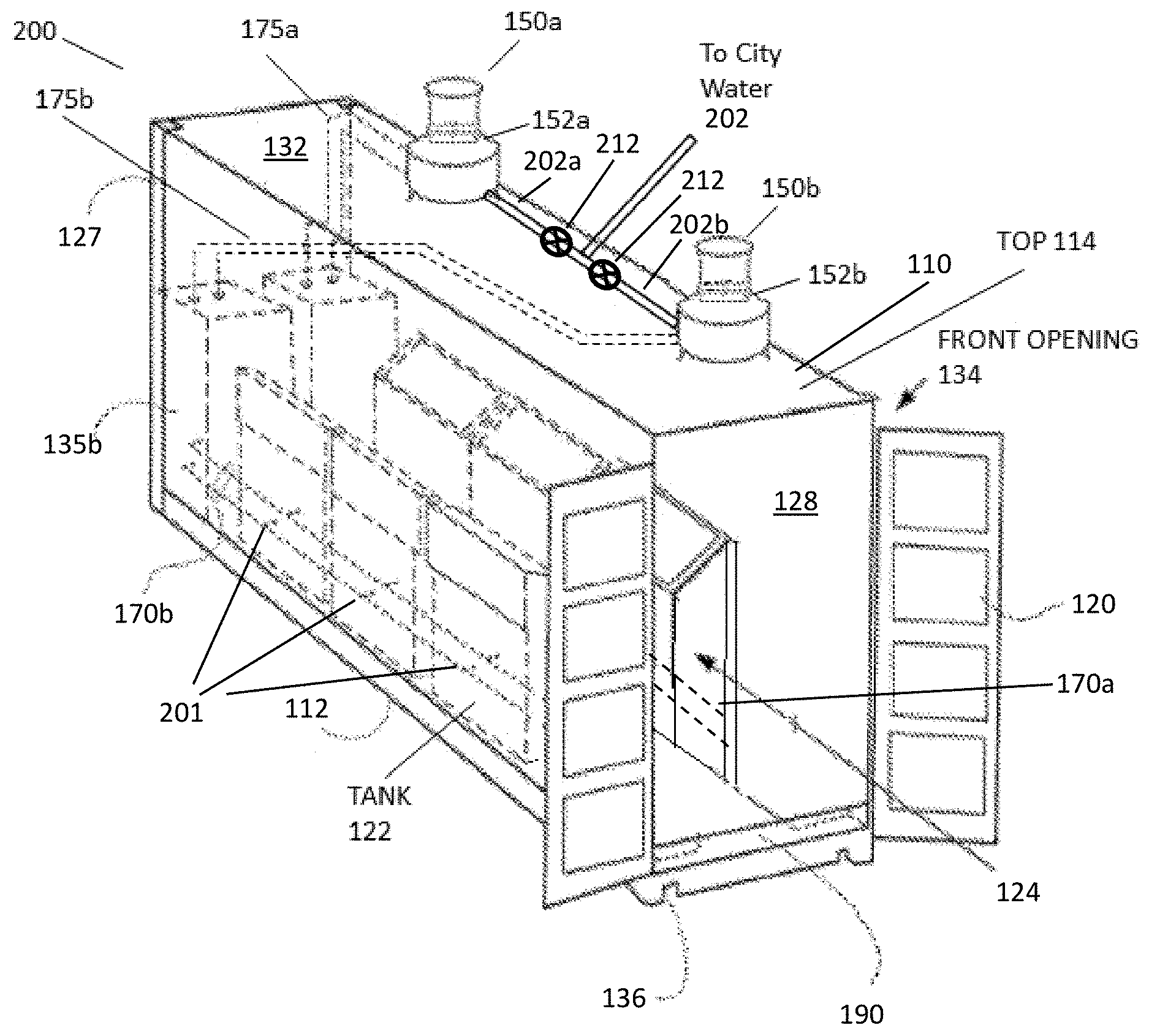
[0021] FIGS. 2-4 illustrate a modular cooling system 200 according to an embodiment. As shown in FIG. 2, in this embodiment system, the cooling system 200 includes six cooling tanks 122 located in a portable container, such as a shipping container 110. Each of the cooling tanks 122 may include racks (not shown) configured to hold electronic equipment, such as servers, hard drives, etc. However, any number of racks/tanks 122 may be located in the shipping container 110, depending of the size of the shipping container 110 and the tanks 122. In an embodiment, the six tanks 122 are operatively configured on independent pump/heat exchanger loops 201. That is, each of the six tanks 122 may be independently supplied with dielectric coolant and the dielectric coolant independently removed from the each of the tanks 122 without effecting the supply or withdrawal of dielectric coolant from the other tanks 122.
[0022] In addition, as illustrated in FIG. 2, three of the tanks 122 may be operatively configured on a first independent pump/heat exchanger circuit 170a, 175a while the other three tanks 122 may be operatively configured on a second independent pump/heat exchanger circuit 170b, 175b. The operation of the first and second independent pump/heat exchanger circuits 170a, 175a, 170b, 175b are discussed in more detail below in regards to FIGS. 5 and 6.
[0023] Also illustrated in FIG. 2 are two cooling towers 150a, 150b located on the top wall 114 of the shipping container 110. In an embodiment, the cooling towers 150a, 150b include liquid-liquid heat exchangers 152a, 152b. In an embodiment, the first liquid is the dielectric coolant used to cool the severs and other electronic equipment in the tanks 122. The second liquid is typically water which may be supplied from the local municipality. Cool municipal water may be provided to the liquid-liquid heat exchangers 152a, 152b via municipal cooling water circuit 202. In an embodiment, the municipal cooling water circuit 202 is divided into a first cooling water circuit 202a which provides cooling water to the first liquid-liquid heat exchanger 152a in the first cooling tower 150a and to a second cooling water circuit 202b which provides cooling water to the second liquid-liquid heat exchanger 152b in the second cooling tower 150b.
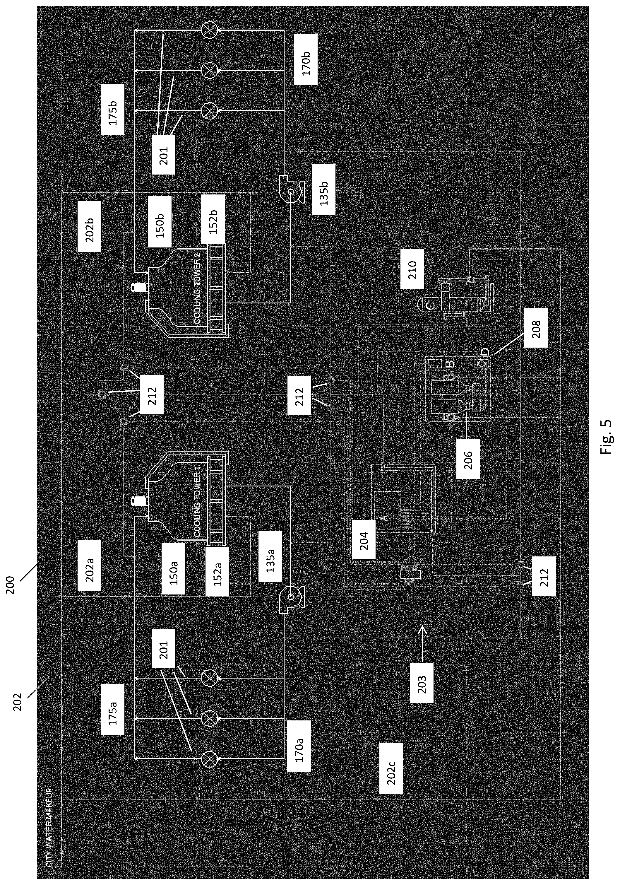
[0024] The modular cooling system 200 also includes a water treatment system 203, illustrated in FIG. 5, which includes a water treatment analyzer/controller 204, an inhibitor dispenser 206, an inhibiter feed pump 208, a biocide dispenser 210 and solenoid valves 212. As discussed in more detail below the solenoid valves 212 may be used to shunt the municipal cooling water from the cooling towers 150s, 150b to the water treatment system 203 for inhibitor and biocide treatment and then back to the cooling towers 150a, 150b after treatment.
[0025] As illustrated in FIG. 5, three of the tanks 122 may be supplied with dielectric coolant via a first dielectric fluid supply circuit 170a with a first pump module 135a and the other three tanks 112 supplied with dielectric coolant via a second dielectric fluid supply circuit 170a with a second pump module 135b. Hot dielectric coolant may be removed from the first three tanks and sent to a first cooling tower 150a to be cooled via a first dielectric fluid removal circuit 175a while hot dielectric coolant from the second three tanks may be sent to a second cooling tower 150b to be cooled via a second dielectric fluid removal circuit 175b.
[0026] The first cooling tower 150a is provided with cooling water, typically from a municipal water line 202 via a first cooling water circuit 202a. The second cooling tower 150b is provided with cooling water, typically from a municipal water line 202 via a second cooling water circuit 202b. The first and second cooling towers 150a, 150b include a respective first heat exchanger 152a and second heat exchanger 152b.
[0027] As shown in FIG. 5, three of the independent pump/heat exchanger loops 201 share water heat exchange on the first cooling water circuit 202a. The other three independent pump/heat exchanger loops 201 share water heat exchange on the second cooling water circuit 202b. In addition, the system 200 includes a third cooling water circuit 202c. Operatively located on the third cooling water circuit 202c is a water treatment system 203. The water treatment system 203 may include an inhibitor dispenser 206 and an inhibitor feed pump 208. The inhibitor 206 provides chemicals which reduce the formation of scale in the plumbing of the modular cooling system 200. In addition, the water treatment system 203 may include a biocide dispenser 210. The biocide dispenser 210 is configured to provide one or more chemicals which destroy, deter, render harmless, or exert a controlling effect on harmful biological organisms in the water from the municipal water system 202, such as bacteria, algae and other biological organisms which may clog the various cooling water circuits 202, 202a, 202b, 202c, if left unchecked. Sampling and control of the water treatment system 203 is managed by a water treatment analyzer/controller 204
[0028] In an embodiment, to address space constraints in the container 110, the water treatment system 200 utilizes solenoid valves 212 to divert water from the first and second water cooling circuits 202a, 202b for a given time period, i.e. water treatment period. During this time period, the water treatment analyzer/controller 204 samples the water for pH, conductivity and bio-hazard materials. Based on the analysis of the water, the water treatment system 203 treats the water to rectify potentially hazardous conditions via the use of chemical treatment, biocide treatment or water blow-down. Water blow-down is a solenoid valve actuated purge of the water into a drain which may be performed if a large amount of minerals or metals are found in the water. Water blow-down allows for the modular water cooling system 200 to be replenished fresh water, rather than merely treating the existing water.
[0029] In an embodiment, once the treatment period is completed for the first water cooling circuit 202a, the water treatment analyzer/controller 204 closes all solenoid valves 212 for the first water cooling circuit 202a. Then, the water treatment analyzer/controller 204 opens solenoid valves 212 for the second water cooling circuit 202b and completes the sampling and mitigation steps for the second water cooling circuit 202b. The water treatment analyzer/controller 204 can automatically switch back and forth between the first and second water cooling circuits 202a, 202b.
[0030] FIGS. 3 and 4 illustrate a portion of a cooling system according to an embodiment. In the embodiment illustrated in FIGS. 3 and 4, water blow-down valves 212 and plumbing are constructed outside of the shipping container 110 to minimize water plumbing within the interior of modular cooling system 200. The blow-down valves 212 and water plumbing are constructed outside of the shipping container 110 because plumbing breaks and leaks within the interior of the modular cooling system 200 can be very detrimental to the modular cooling system 200. A single fresh city water input line is introduced into the shipping container 110 to supply fresh water to the water treatment system 203 to improve efficiency of the water treatment system 203. This minimizes water plumbing ingress points to the shipping container 110.
[0031] FIG. 6 is a flow chart illustrating a method 300 of operating a modular cooling system 200 according to an embodiment. Specifically, FIG. 6 illustrates an embodiment drawn to a method 300 of operating a cooling system 200 including at least two water cooling circuits 202a, 202b, an analyzer/controller 204 configured to analyze water in the at least two water cooling circuits 202a, 202b and solenoid valves 212 operably connected to the at least two water cooling circuits 202a, 202b. The method 300 comprises a step 302 of opening solenoid valves 212 associated with a first water cooling circuit 202a of the at least two water cooling circuits 202a, 202b to allow cooling water to flow to the analyzer/controller 204 and steps 306 of detecting if the cooling water comprises one or more impurities. Specifically, in an embodiment, the analyzer/controller 204 performs a step 308 of determining if any there are any chemical, e.g. scale forming chemicals, above a predetermined threshold. If the concentration of the chemical species is above the threshold, a step 310 of treating the cooling water with a chemical is performed. If the chemicals detected in the cooling water are below the predetermined threshold, a step 312 of determining if the cooling water includes any biological species above a predetermined threshold for biological species is performed. If the concentration of the biological species are above the predetermined threshold, the cooling water is treated with one or more biocides in step 314. If the concentration of the biological species is below the predetermined threshold, an optional check is made to verify which valve is open in step 316 and the first solenoid valve is closed in step 318. In an embodiment, the step 314 of determining if the concentration of the biological impurities is above the predetermined threshold may be performed prior to the step 310 of determining the concentration of the chemical impurities is above the predetermined threshold.
[0032] When the first solenoid valve is closed in step 318, the cooling water is sent to the first heat exchanger 152a in the first cooling tower 150a in step 320. In step 322, hot dielectric coolant from the first portion of the tanks 122 is operably connected to the first dielectric fluid removal circuit 175a is also sent to the first heat exchanger 152a in the first cooling tower 150a. In this manner, cooling water may be used to remove heat from the hot dielectric coolant from the first portion of the tanks 122.
[0033] A second solenoid valve 212 associated with the second cooling circuit 202b may then be opened in step 324. Water in the second cooling circuit 202b is sent to the analyzer/controller 204 in step 326. Similar to the steps above, the concentration of chemicals and biologicals in the cooling water is analyzed to determine if they are above predetermined thresholds in step 304. Specifically, in step 308, the cooling water is analyzed to determine if the concentration of chemicals is above a predetermined threshold. If the concentration of the chemical impurities is above the predetermined threshold, the cooling water is treated with chemicals to mitigate or eliminate the chemical impurities in step 310. If the concentration of the chemical impurities is below the predetermined threshold, the cooling is analyzed to determine if the biological impurities are below the predetermined threshold in step 312. If the concentration of the biological impurities is above the predetermined threshold, the cooling water is treated with a biocide in step 314. If the concentration of the biological impurities is below the predetermined threshold, an optional check is made to verify which valve is open in step 316 and the second solenoid value 212 is closed in step 324. The cooling water from the second cooling circuit 202b is then provided to the second heat exchanger 152b in the second cooling tower 150b in step 326. Hot dielectric fluid from the second portion of the tanks 122 is also provided to the second heat exchanger 152b in the second cooling tower 150b in step 328.
[0034] As illustrated in FIG. 6, the method can be repeated as necessary by opening the first solenoid valve in step 304 and restarting the method.
[0035] An embodiment is drawn to a cooling system 200 including at least two water cooling circuits 202a, 202b, an analyzer/controller 204 configured to analyze water in the at least two water cooling circuits 202a, 202b and solenoid valves 212 operably connected to the at least two water cooling circuits 202a, 202b. The cooling system 200 is configured such that opening solenoid valves 212 associated with a first water cooling circuit 202a of the at least two water cooling circuits 202a, 202b allows cooling water to flow to the analyzer/controller 204 and the cooling water to be treated if the analyzer/controller 204 detects one or more impurities in the cooling water above one or more predetermined thresholds 304.
[0036] In an embodiment, the cooling system 200 is configured such that when the solenoid valves 212 associated with the first water cooling circuit 202a are closed, cooling water flows to a first cooling tower 150a. In an embodiment, the first cooling tower 150a comprises a first heat exchanger 152a and the first cooling tower 150a is located on top of a shipping container 110. In an embodiment, the cooling system 200 further comprises an inhibitor dispenser 206 configured to dispense de-scaling chemicals into the cooling water and a biocide dispenser 210 configured to dispense a biocide into the cooling water.
[0037] In an embodiment, the analyzer/controller 204, the inhibiter dispenser 206 and the biocide dispenser 210 are located inside a shipping container 110. In an embodiment, the cooling system 200 further comprises a plurality of tanks 122 located in the shipping container 110, the tanks 122 containing electronic equipment and a dielectric fluid, wherein hot dielectric fluid from a first portion of the plurality of tanks 122 is provided to the first heat exchanger 1152a to be cooled by the cooling water in the first water cooling circuit 202a. In an embodiment, solenoid valves 212 associated with a second water cooling circuit 202b of the at least two water cooling circuits 202a, 202b are closed when the solenoid valves 212 associated with the first cooling water circuit 202a are open. In an embodiment, the solenoid valves 212 associated with the second water cooling circuit 202b may be opened when the solenoid valves 212 associated with first cooling water circuit are closed.
[0038] In an embodiment, the cooling system 200 further comprises a second cooling tower 150b located on top to the shipping container 110, the second cooling tower 150b comprising a second heat exchanger 152b and a plurality of tanks 122 located in the shipping container 110, the tanks 122 containing electronic equipment and a dielectric fluid, wherein hot dielectric fluid from the a second portion of the plurality of tanks 122 is provided to the second heat exchanger 152b to be cooled by the cooling water in the second water cooling circuit 202b.
[0039] Although the foregoing refers to particular preferred embodiments, it will be understood that the invention is not so limited. It will occur to those of ordinary skill in the art that various modifications may be made to the disclosed embodiments and that such modifications are intended to be within the scope of the invention. All of the publications, patent applications and patents cited herein are incorporated herein by reference in their entirety.
* * * * *
D00000
D00001
D00002
D00003
D00004
D00005
D00006
XML
uspto.report is an independent third-party trademark research tool that is not affiliated, endorsed, or sponsored by the United States Patent and Trademark Office (USPTO) or any other governmental organization. The information provided by uspto.report is based on publicly available data at the time of writing and is intended for informational purposes only.
While we strive to provide accurate and up-to-date information, we do not guarantee the accuracy, completeness, reliability, or suitability of the information displayed on this site. The use of this site is at your own risk. Any reliance you place on such information is therefore strictly at your own risk.
All official trademark data, including owner information, should be verified by visiting the official USPTO website at www.uspto.gov. This site is not intended to replace professional legal advice and should not be used as a substitute for consulting with a legal professional who is knowledgeable about trademark law.