Dynamic Bending Light Module
Warner; Gavin
U.S. patent application number 16/042799 was filed with the patent office on 2020-01-23 for dynamic bending light module. This patent application is currently assigned to Valeo North America, Inc.. The applicant listed for this patent is Valeo North America, Inc.. Invention is credited to Gavin Warner.
| Application Number | 20200025349 16/042799 |
| Document ID | / |
| Family ID | 69161687 |
| Filed Date | 2020-01-23 |
| United States Patent Application | 20200025349 |
| Kind Code | A1 |
| Warner; Gavin | January 23, 2020 |
DYNAMIC BENDING LIGHT MODULE
Abstract
A lighting module and a headlamp for vehicle lighting are provided. The lighting module includes a dynamic bending light module; and a lens that is situated in operative relationship with the dynamic bending light module; wherein the lens has a thin aspect.
| Inventors: | Warner; Gavin; (Seymour, IN) | ||||||||||
| Applicant: |
|
||||||||||
|---|---|---|---|---|---|---|---|---|---|---|---|
| Assignee: | Valeo North America, Inc. Troy MI |
||||||||||
| Family ID: | 69161687 | ||||||||||
| Appl. No.: | 16/042799 | ||||||||||
| Filed: | July 23, 2018 |
| Current U.S. Class: | 1/1 |
| Current CPC Class: | F21S 41/141 20180101; B60Q 1/0041 20130101; F21S 41/25 20180101; F21Y 2115/10 20160801; B60Q 1/12 20130101; F21S 41/635 20180101 |
| International Class: | F21S 41/63 20060101 F21S041/63; F21S 41/141 20060101 F21S041/141 |
Claims
1. A lighting module comprising: a dynamic bending light module configured to generate an elbow profile of a light pattern; an alignment module separate from the dynamic bending light module, the alignment module configured to provide light to a spread region of the light pattern; and a lens that is situated in operative relationship with the dynamic bending light module and the alignment module; wherein the lens has a thin aspect.
2. (canceled)
3. The lighting module of claim 1, further comprising: a drive device configured to rotate the dynamic bending light module.
4. The lighting module of claim 3, wherein the drive device is configured to rotate the dynamic bending light module with an angle of rotation of .+-.15 degrees.
5. The lighting module of claim 3, wherein the rotation is controlled by a controller coupled to a steering wheel sensor.
6. (canceled)
7. A headlamp for a vehicle, the headlamp comprising: a lighting module including a dynamic bending light module configured to generate an elbow profile of a light pattern; an alignment module separate from the dynamic bending light module, the alignment module configured to provide light to a spread region of the light pattern; and a lens that is situated in operative relationship with the dynamic bending light module and the alignment module; wherein the lens has a thin aspect.
8. (canceled)
9. The headlamp of claim 7, wherein the lighting module further includes: a drive device configured to rotate the dynamic bending light module.
10. The headlamp of claim 9, wherein the drive device is configured to rotate the dynamic bending light module with an angle of rotation of .+-.15 degrees.
11. The headlamp of claim 9, wherein the rotation is controlled by a controller coupled to a steering wheel sensor.
12. (canceled)
13. A dynamic bending light module, the dynamic bending light module comprising: a collector lens; and one or more light emitting diodes, wherein the collector lens and the one or more light emitting diodes are configured to rotate independently of an alignment module, and are situated in an operative relationship with a lens having a thin aspect wherein the dynamic bending light module is configured to generate an elbow profile.
14. The module of claim 13, further comprising: a drive device coupled to the collector lens and the one or more light emitting diodes.
15. The lighting module of claim 14, wherein the drive device is configured to rotate the dynamic bending light module with an angle of rotation of .+-.15 degrees.
16. The module of claim 13, wherein the module is included in a headlamp.
17. (canceled)
18. The module of claim 13, wherein the rotation is controlled by a controller coupled to a steering wheel sensor.
19. (canceled)
Description
BACKGROUND
[0001] The invention relates to the domain of lighting and/or signaling, in particular for a motor vehicle. More specifically, the invention relates to a lighting module for a motor vehicle, as well as a lighting device including such a lighting module.
[0002] Motor vehicles contain numerous lighting devices for both interior and exterior illumination. For example, exterior vehicle lighting devices may perform stop lamp functions, tail lamp functions, headlamp functions, daytime running light functions, dynamic bending light functions, and fog lamp functions. Numerous studies have found that nighttime visibility is a key to highway safety.
[0003] Lighting and/or signaling devices may include one or more lighting modules mounted rotatably about an axis, notably to address the problems of cornering lights. Such rotary modules are particularly suited to performing directional lighting functions, better known as dynamic bending light (DBL), in which the objective is to dynamically illuminate the bend when the vehicle is turning. Since the lighting module is mounted pivotingly about a substantially vertical axis of rotation, the beam projected from the headlamp can be oriented towards the inside of a bend when cornering, instead of along the longitudinal axis of the vehicle.
[0004] The foregoing "Background" description is for the purpose of generally presenting the context of the disclosure. Work of the inventor, to the extent it is described in this background section, as well as aspects of the description which may not otherwise qualify as prior art at the time of filing, are neither expressly or impliedly admitted as prior art against the present invention.
SUMMARY
[0005] The present disclosure relates to a lighting module that includes a dynamic bending light module; and a lens that is situated in operative relationship with the dynamic bending light module; wherein the lens has a thin aspect.
[0006] In one aspect, the lighting module further includes an alignment module separate from the dynamic bending light module.
[0007] In one aspect, the lighting module further includes a drive device configured to rotate the dynamic bending light module.
[0008] In one aspect, the drive device is configured the dynamic bending light module with an angle of rotation of .+-.15 degrees.
[0009] In one aspect, the rotation is controlled by a controller coupled to a steering wheel sensor.
[0010] In one aspect, the dynamic bending light module is configured to generate a beam pattern having a cut off profile.
[0011] The foregoing paragraphs have been provided by way of general introduction, and are not intended to limit the scope of the following claims. The described embodiments, together with further advantages, will be best understood by reference to the following detailed description taken in conjunction with the accompanying drawings.
BRIEF DESCRIPTION OF THE DRAWINGS
[0012] A more complete appreciation of the disclosure and many of the attendant advantages thereof will be readily obtained as the same becomes better understood by reference to the following detailed description when considered in connection with the accompanying drawings, wherein:
[0013] FIG. 1 illustrates a front-end of an exemplary motor vehicle according to one example;
[0014] FIG. 2 is a schematic of an exemplary roadway, a motor vehicle, and a light distribution pattern according to one example;
[0015] FIG. 3A is a schematic that shows a thin lens module according to one example;
[0016] FIG. 3B is a schematic that shows a thin lens module having a rotating light module according to one example; and
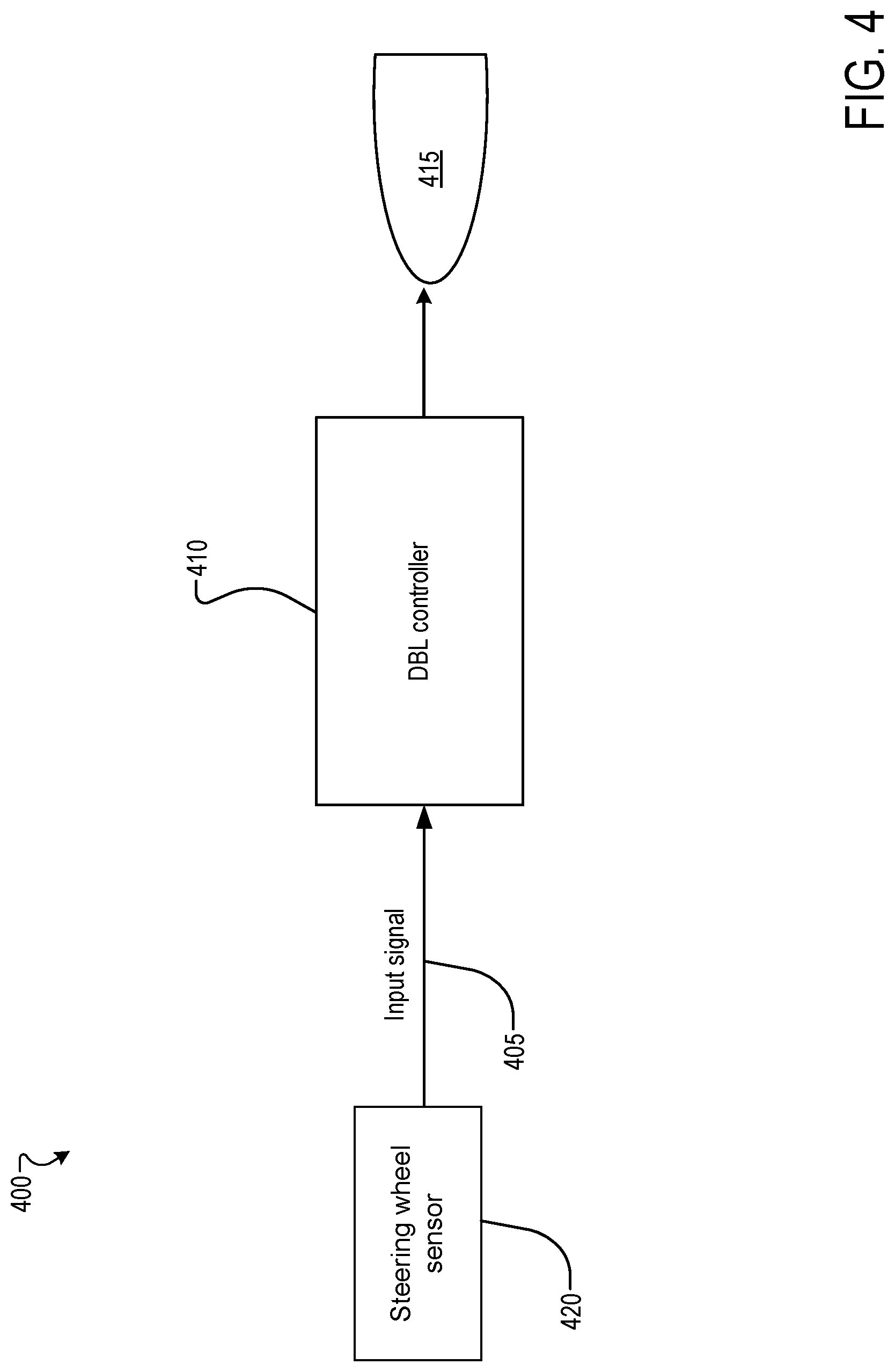
[0017] FIG. 4 is a block diagram of a low beam headlamp assembly according to one example.
DETAILED DESCRIPTION
[0018] The following descriptions are meant to further clarify the present disclosure by giving specific examples and embodiments of the disclosure. These embodiments are meant to be illustrative rather than exhaustive. The full scope of the disclosure is not limited to any particular embodiment disclosed in the specification, but rather is defined by the claims.
[0019] In the interest of clarity, not all of the features of the implementations described herein are shown and described in detail. It will be appreciated that in the development of any such actual implementation, numerous implementation-specific decisions will be made in order to achieve the developer's specific goals, such as compliance with application- and business-related constraints, and that these specific goals will vary from one implementation to another and from one developer to another.
[0020] Referring now to the drawings, wherein like reference numerals designate identical or corresponding parts throughout several views, the following description relates to a lighting module for a motor vehicle, as well as a lighting device including such a lighting module. More specifically, the description relates to a thin lens module adapted for adaptive front lighting system.
[0021] Conventional thin lens module cannot be adapted for adaptive front lighting system. When the module swivels both the kink and flat swivel.
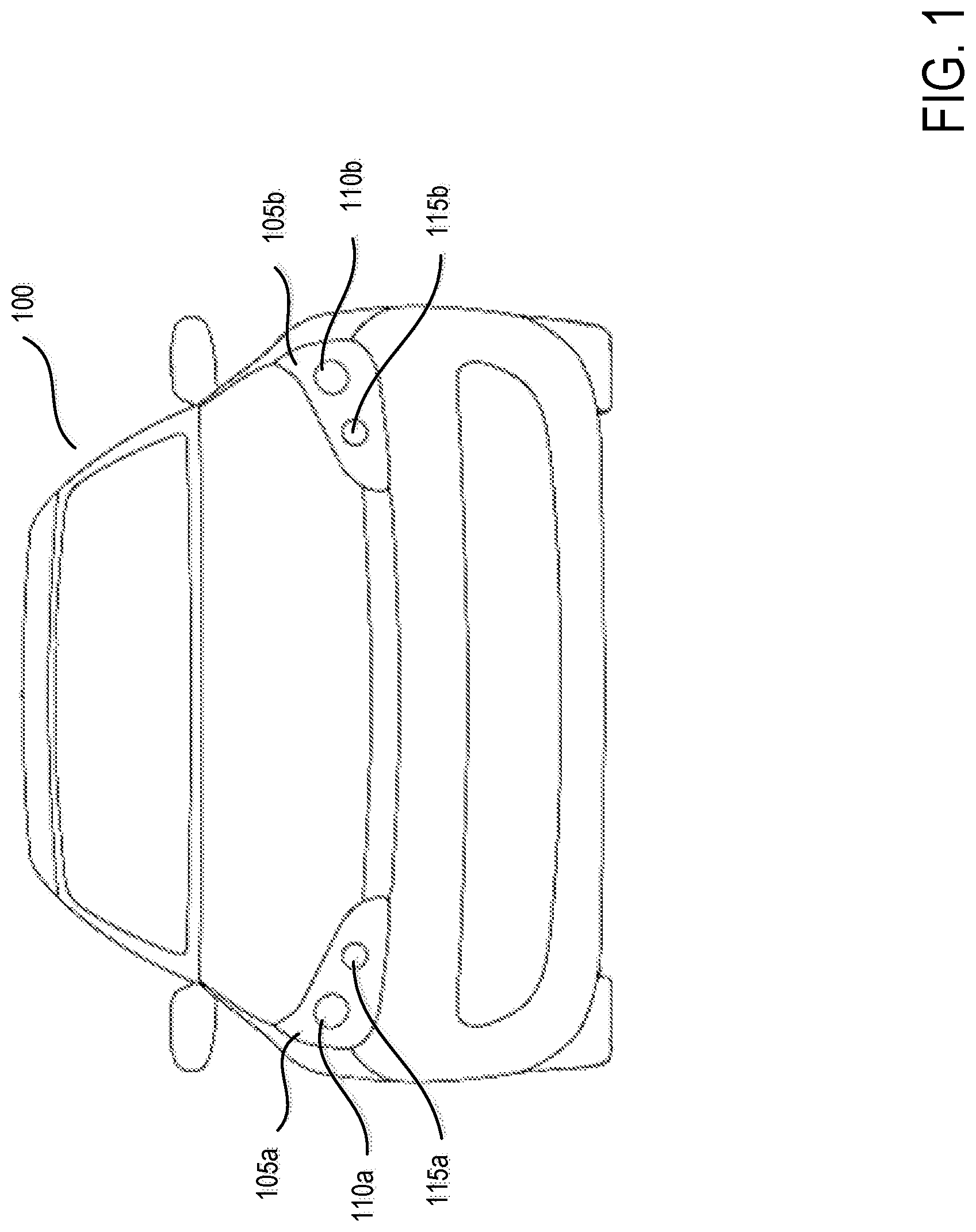
[0022] FIG. 1 illustrates a front-end of an exemplary motor vehicle 100. Motor vehicle 100 includes two headlamp assemblies 105a and 105b. Headlamp assemblies 105a and 105b include low beam headlamps 110a and 110b (also referred to as a lower or dipped beam) and high beam headlamps 115a and 115b (also referred to as a main or driving beam). Typically, the low beam headlamps 110a and 110b are used whenever another vehicle is on the road directly ahead of motor vehicle 100 and/or whenever another vehicle is approaching motor vehicle 100 from an opposite direction. In one implementation, the low beam headlamps 110a and 110b may include a thin lens module having a rotatable dynamic bending light (DBL) function.
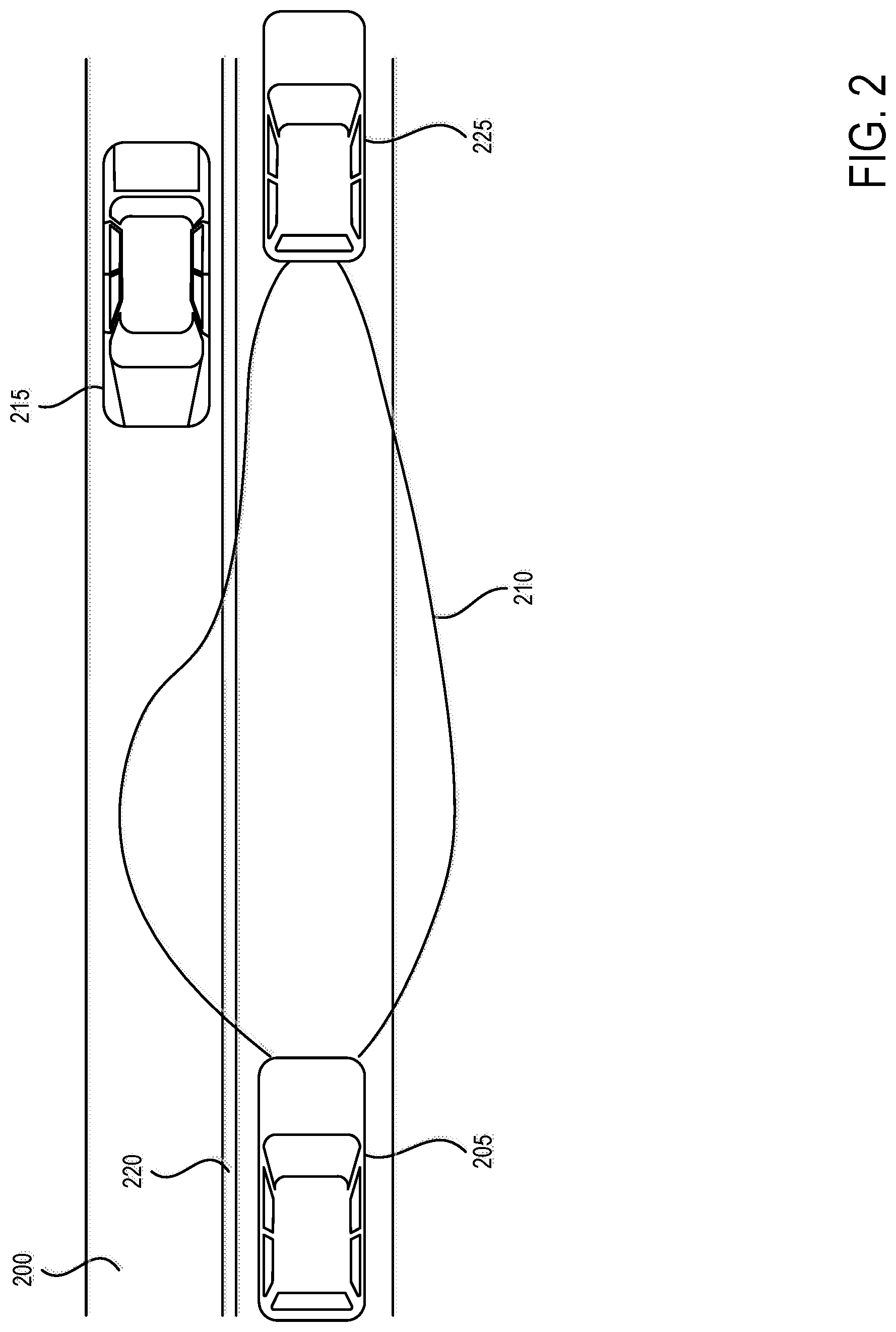
[0023] FIG. 2 is a schematic diagram of an exemplary roadway 200, motor vehicle 205, and a light distribution pattern 210 for low beam headlamps of motor vehicle 205. Light distribution pattern 210 for the low beam headlamps of motor vehicle 205 can be optically designed to minimize the amount of light that crosses the centerline 220 of roadway 200 to reduce dazzle (a blinding effect from the headlights) to a driver of an oncoming motor vehicle 215. Additionally, a range of the low beam headlamps of motor vehicle 205 can be limited to reduce dazzle in the rear-view mirror for a driver of motor vehicle 225 directly ahead of motor vehicle 205 driving in the same direction.
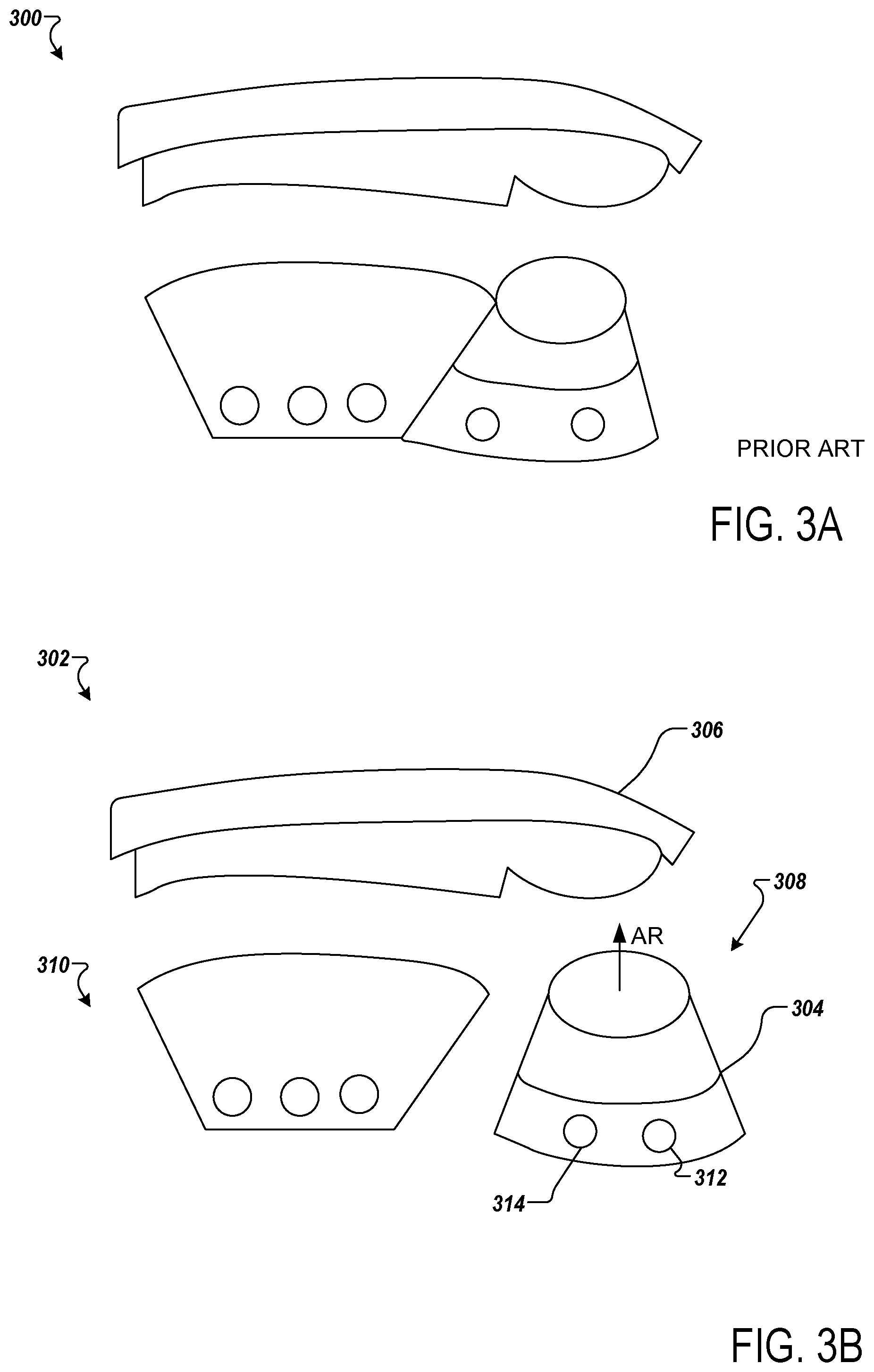
[0024] FIG. 3A is a schematic that shows a thin lens module 300 according to one example.
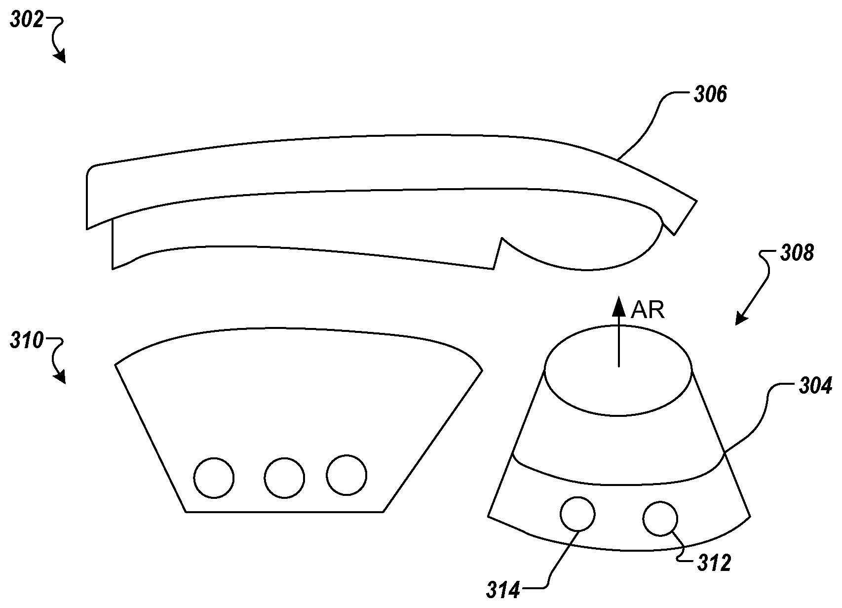
[0025] FIG. 3B is a schematic that shows a thin lens module 302 having a DBL module 304 according to one example. The thin lens module 302 may include an outer lens 306 and an inner lens 308. The inner lens 308 may include an alignment module (or flat module) 310 and the DBL module 304. The alignment module provides light to the spread region of the pattern. The alignment module may include a projection lens. The DBL module 304 is separate from the alignment module 310. The DBL module 304 is configured to rotate about axis of rotation AR. The DBL module may include a projection lens and an LED board. The LED board and the collector lens rotate about the axis of rotation. In one implementation, the angle of rotation is .+-.15 degrees. The DBL and the alignment module are substantially close to each other. The outer lens 306 is designed not to block light.
[0026] The outer lens 306 may have a thin aspect and is generally narrow along its length. The aspect in thin aspect refers to aspect ratio which is the ratio of height H to width W, or H/W. Thus, a thin aspect ratio refers to a headlight which is tall and narrow. The headlamp provides a beam pattern that conforms to society of automotive engineers (SAE) and/or economic commission for Europe (ECE) standards.
[0027] The outer lens 306 may be transparent and may be made from a plastic such as polycarbonate (PC), polymethyl methacrylate, polypropylene, polybutylene terephthalate, or the like. The outer lens 306 may have an outer surface that is adapted or shaped to follow a contour or surface of the vehicle for styling purposes and aerodynamic benefits.
[0028] The thin lens module 302 may be included in a housing that includes one or more light modules. The DBL module 304 may include at least one light source. The light source may include at least one LED or an array of LEDs. In one implementation, the light source may include at least one OLED or an array of OLEDs or polymer light emitting diodes (PLEDs) and/or monolithic LEDs. For example, the light source may be an areal/planar luminous field. In one example, the light source may be a laser. The DBL provides a beam pattern having a cut-off profile known by the term "kink" or "elbow". In FIG. 3, the DBL module 304 includes two LED couplers 312 and 314.
[0029] The thin lens module 302 may include a drive device coupled to the DBL module 304. The drive device may include an electric motor, for example a step-by-step or stepper motor. The drive device is configured to rotate the DBL module 304 about the axis of rotation AR. The drive device is configured to rotate and then goes back to the original position. The DBL module 304 provides a consistent pattern as the module rotates. The cut off profile or "kink" is designed to provide high performance in the Insurance Institute for Highway Safety (IIHS) tests and ratings.
[0030] FIG. 4 is a block diagram of a low beam headlamp assembly 400 according to one example. The low beam headlamp assembly includes a DBL module 415. An input signal 405 is connected to the DBL module controller 410. A single DBL controller 410 can be employed for both a right and left low beam headlamp assembly such that the DBL module 415 are driven in a synchronized manner. The input signal 405 may be generated by a controller based on data from a steering wheel sensor 420 that is sensitive to the trajectory of the vehicle 100. In one implementation, the DBL controller 410 may be coupled to a steering wheel of the vehicle 100. In other implementations, the controller may be coupled to other devices that are sensitive to the trajectory of the vehicle 100. The devices may include a camera or a GPS navigator in addition to or instead of the steering wheel sensor. The controller includes any embedded system, computer, processor, electronic control unit (ECU), or microcontroller of the vehicle 100. In one embodiment, the controller is an ECU dedicated for controlling one or more lighting devices, for example, low beam headlamp assembly 400.
[0031] A system which includes the features in the foregoing description provides numerous advantages to users. In particular, embodiments describe herein provide a thin lens module that is adapted to provide DBL function.
[0032] While certain embodiments have been described herein, these embodiments are presented by way of example only, and are not intended to limit the scope of the disclosure. Using the teachings in this disclosure, a person having ordinary skill in the art can modify and adapt the disclosure in various ways, making omissions, substitutions, and/or changes in the form of the embodiments described herein, without departing from the spirit of the disclosure. Moreover, in interpreting the disclosure, all terms should be interpreted in the broadest possible manner consistent with the context. The accompanying claims and their equivalents are intended to cover such forms or modifications, as would fall within the scope and spirit of the disclosure.
* * * * *
D00000
D00001
D00002
D00003
D00004
XML
uspto.report is an independent third-party trademark research tool that is not affiliated, endorsed, or sponsored by the United States Patent and Trademark Office (USPTO) or any other governmental organization. The information provided by uspto.report is based on publicly available data at the time of writing and is intended for informational purposes only.
While we strive to provide accurate and up-to-date information, we do not guarantee the accuracy, completeness, reliability, or suitability of the information displayed on this site. The use of this site is at your own risk. Any reliance you place on such information is therefore strictly at your own risk.
All official trademark data, including owner information, should be verified by visiting the official USPTO website at www.uspto.gov. This site is not intended to replace professional legal advice and should not be used as a substitute for consulting with a legal professional who is knowledgeable about trademark law.