Sprocket Gerotor Pump
Bennett, SR.; Andy ; et al.
U.S. patent application number 16/039899 was filed with the patent office on 2020-01-23 for sprocket gerotor pump. This patent application is currently assigned to GM Global Technology Operations LLC. The applicant listed for this patent is GM Global Technology Operations LLC. Invention is credited to Andy Bennett, SR., Sean M. McGowan.
| Application Number | 20200025198 16/039899 |
| Document ID | / |
| Family ID | 69147906 |
| Filed Date | 2020-01-23 |

| United States Patent Application | 20200025198 |
| Kind Code | A1 |
| Bennett, SR.; Andy ; et al. | January 23, 2020 |
SPROCKET GEROTOR PUMP
Abstract
A sprocket gerotor pump includes an outer gerotor gear configured to rotate about a first axis. The outer gerotor gear includes an outer gear body including a plurality of internal gear teeth extending from the outer gear body toward the first axis. The sprocket gerotor pump includes an inner gerotor gear configured to rotate about a second axis. The inner gerotor gear includes an inner gear body and a plurality of external gear teeth extending from the inner gerotor gear away from the second axis. The external gear teeth mesh with the internal gear teeth. Rotating the outer gerotor gear causes rotation of the inner gerotor gear. The sprocket gerotor pump further includes a sprocket integrally coupled with the outer gerotor gear such that the sprocket and the outer gerotor gear collectively form a one-piece structure. The sprocket is driven by a chain.
| Inventors: | Bennett, SR.; Andy; (Rochester Hills, MI) ; McGowan; Sean M.; (Northville, MI) | ||||||||||
| Applicant: |
|
||||||||||
|---|---|---|---|---|---|---|---|---|---|---|---|
| Assignee: | GM Global Technology Operations
LLC Detroit MI |
||||||||||
| Family ID: | 69147906 | ||||||||||
| Appl. No.: | 16/039899 | ||||||||||
| Filed: | July 19, 2018 |
| Current U.S. Class: | 1/1 |
| Current CPC Class: | F04C 2240/20 20130101; F04C 2/102 20130101; F01M 2001/0238 20130101; F01M 2001/0253 20130101; F04C 2210/206 20130101; F04C 2/084 20130101; F04C 15/0061 20130101; F04C 2210/14 20130101; F16N 13/20 20130101; F01M 1/02 20130101 |
| International Class: | F04C 15/00 20060101 F04C015/00; F04C 2/10 20060101 F04C002/10; F04C 2/08 20060101 F04C002/08 |
Claims
1. A sprocket gerotor pump, comprising: an outer gerotor gear configured to rotate about a first axis, wherein the outer gerotor gear includes an outer gear body including a plurality of internal gear teeth extending from the outer gear body toward the first axis; an inner gerotor gear configured to rotate about a second axis, wherein the second axis is spaced apart from the first axis, the inner gerotor gear includes an inner gear body and a plurality of external gear teeth extending from the inner gear body away from the second axis, and the plurality of external gear teeth meshes with the plurality of the internal gear teeth such that rotation of the outer gerotor gear causes rotation of the inner gerotor gear; and a sprocket integrally coupled with the outer gerotor gear such that the sprocket and the outer gerotor gear collectively form a one-piece structure.
2. The sprocket gerotor pump of claim 1, wherein the sprocket includes a ring and a plurality of external sprocket teeth extending from the ring.
3. The sprocket gerotor pump of claim 2, wherein the ring is directly coupled to the outer gear body, the first axis is parallel to the second axis, and each of the plurality of external sprocket teeth is directly coupled to the ring.
4. The sprocket gerotor pump of claim 3, wherein the plurality of internal gear teeth defines an inner cavity, the inner cavity is sized to receive the inner gerotor gear, and the inner gerotor gear is entirely disposed inside the inner cavity.
5. The sprocket gerotor pump of claim 4, further comprising a housing partially encasing the outer gerotor gear.
6. The sprocket gerotor pump of claim 5, further comprising a cover partially encasing the outer gerotor gear.
7. The sprocket gerotor pump of claim 6, wherein the housing and the cover collectively define an annular gap therebetween.
8. The sprocket gerotor pump of claim 7, wherein the annular gap is sized to receive the plurality of external sprocket teeth.
9. The sprocket gerotor pump of claim 8, further comprising a chain meshed with the plurality of external sprocket teeth.
10. The sprocket gerotor pump of claim 9, wherein the annular gap receives the plurality of external sprocket teeth and a portion of the chain.
11. A vehicle system, comprising: an engine block; a sprocket gerotor pump supported by the engine block, wherein the sprocket gerotor pump includes: an outer gerotor gear configured to rotate about a first axis, wherein the outer gerotor gear includes an outer gear body including a plurality of internal gear teeth extending from the outer gear body toward the first axis; an inner gerotor gear configured to rotate about a second axis, wherein the first axis is parallel to the second axis, the second axis is spaced apart from the first axis, the inner gerotor gear includes an inner gear body and a plurality of external gear teeth extending from the inner gear body away from the second axis, and the plurality of external gear teeth meshes with the plurality of the internal gear teeth such that rotation of the outer gerotor gear causes rotation of the inner gerotor gear, the plurality of internal gear teeth defines an inner cavity, the inner cavity is sized to receive the inner gerotor gear, and the inner gerotor gear is entirely disposed inside the inner cavity; and a sprocket integrally coupled with the outer gerotor gear such that the sprocket and the outer gerotor gear collectively form a one-piece structure.
12. The vehicle system of claim 11, wherein the sprocket includes a ring and a plurality of external sprocket teeth extending from the ring.
13. The vehicle system of claim 12, wherein the ring is directly coupled to the outer gear body, the first axis is parallel to the second axis, and each of the plurality of external sprocket teeth is directly coupled to the ring.
14. The vehicle system of claim 13, wherein the plurality of internal gear teeth defines an inner cavity, the inner cavity is sized to receive the inner gerotor gear, and the inner gerotor gear is entirely disposed inside the inner cavity.
15. The vehicle system of claim 14, further comprising a housing partially encasing the outer gerotor gear.
16. The vehicle system of claim 15, further comprising a cover partially encasing the outer gerotor gear.
17. The vehicle system of claim 16, wherein the housing and the cover collectively define an annular gap therebetween.
18. The vehicle system of claim 17, wherein the annular gap is sized to receive the plurality of external sprocket teeth.
19. The vehicle system of claim 18, further comprising a chain meshed with the plurality of external sprocket teeth, the annular gap receives the plurality of external sprocket teeth and a portion of the chain.
20. A vehicle system, comprising: an internal combustion engine including an engine block; and a sprocket gerotor pump supported by the engine block, wherein the engine block is in direct contact with the sprocket gerotor pump and includes: an outer gerotor gear configured to rotate about a first axis, wherein the outer gerotor gear includes an outer gear body including a plurality of internal gear teeth extending from the outer gear body toward the first axis; an inner gerotor gear configured to rotate about a second axis, wherein the first axis is parallel to the second axis, the second axis is spaced apart from the first axis, the inner gerotor gear includes an inner gear body and a plurality of external gear teeth extending from the inner gear body away from the second axis, and the plurality of external gear teeth meshes with the plurality of the internal gear teeth such that rotation of the outer gerotor gear causes rotation of the inner gerotor gear; a sprocket integrally coupled with the outer gerotor gear such that the sprocket and the outer gerotor gear collectively form a one-piece structure, wherein the sprocket includes a ring and a plurality of external sprocket teeth extending from the ring, the ring is directly coupled to the outer gear body, and each of the plurality of external sprocket teeth is directly coupled to the ring, each of the plurality of external sprocket teeth extend away from the first axis; a housing partially encasing the outer gerotor gear; a cover partially encasing the outer gerotor gear, wherein the housing and the cover collectively define an annular gap therebetween; and a chain meshed with the plurality of external sprocket teeth, wherein the annular gap solely receives the plurality of external sprocket teeth and a portion of the chain.
Description
INTRODUCTION
[0001] The present disclosure relates to a sprocket gerotor pump. Specifically, the present disclosure describes a gerotor pump integrated with a sprocket.
[0002] Vehicle systems may include pumps for supplying lubricant to one or more vehicle components. These pumps have to be accommodated within the vehicle systems. It is therefore desirable to develop a pump with minimal package size.
SUMMARY
[0003] The present disclosure describes a gerotor pump that integrates a sprocket. By integrally coupling the sprocket to the outer gerotor gear, the package size and the mass of the sprocket gerotor pump is minimized. The sprocket gerotor pump may serve as a supply pump or a scavenge pump. In some embodiments, the sprocket gerotor pump may be part of a vehicle system. The vehicle system may include an internal combustion engine having an engine block. The sprocket gerotor pump is supported by the engine block. For instance, the engine block may be in direct contact with the sprocket gerotor pump. The sprocket gerotor pump includes an outer gerotor gear configured to rotate about a first axis. The outer gerotor gear includes an outer gear body including a plurality of internal gear teeth extending from the outer gear body toward the first axis. The sprocket gerotor pump includes an inner gerotor gear configured to rotate about a second axis. The first axis is parallel to the second axis. The second axis is spaced apart from the first axis. The inner gerotor gear includes an inner gear body and a plurality of external gear teeth extending from the inner gear body away from the second axis. The plurality of external gear teeth meshes with the plurality of the internal gear teeth such that rotation of the outer gerotor gear causes rotation of the inner gerotor gear. The sprocket gerotor pump includes a sprocket integrally coupled with the outer gerotor gear such that the sprocket and the outer gerotor gear collectively form a one-piece structure. The sprocket includes a ring and a plurality of external sprocket teeth extending from the ring. The ring is directly coupled to the outer gear body. Each of the plurality of external sprocket teeth is directly coupled to the ring. Each of the plurality of external sprocket teeth extend away from the first axis. The sprocket gerotor pump includes a housing partially encasing the outer gerotor gear. The sprocket gerotor pump includes a cover partially encasing the outer gerotor gear. The housing and the cover collectively define an annular gap therebetween. The sprocket gerotor pump includes a chain meshed with the plurality of external sprocket teeth. The annular gap solely receives the plurality of external sprocket teeth and a portion of the chain.
[0004] The above features and advantages and other features and advantages of the present disclosure are readily apparent from the following detailed description of the best modes for carrying out the disclosure when taken in connection with the accompanying drawings.
BRIEF DESCRIPTION OF THE DRAWINGS
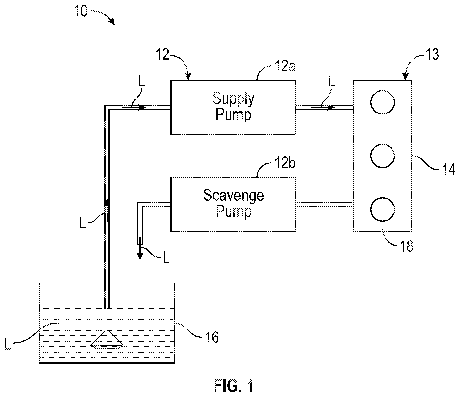
[0005] FIG. 1 is a schematic illustration of a vehicle including an internal combustion engine, a lubricant source, and a sprocket gerotor pump in fluid communication with the lubricant source and the internal combustion engine, wherein the sprocket gerotor pump may be a supply pump or a scavenge pump.
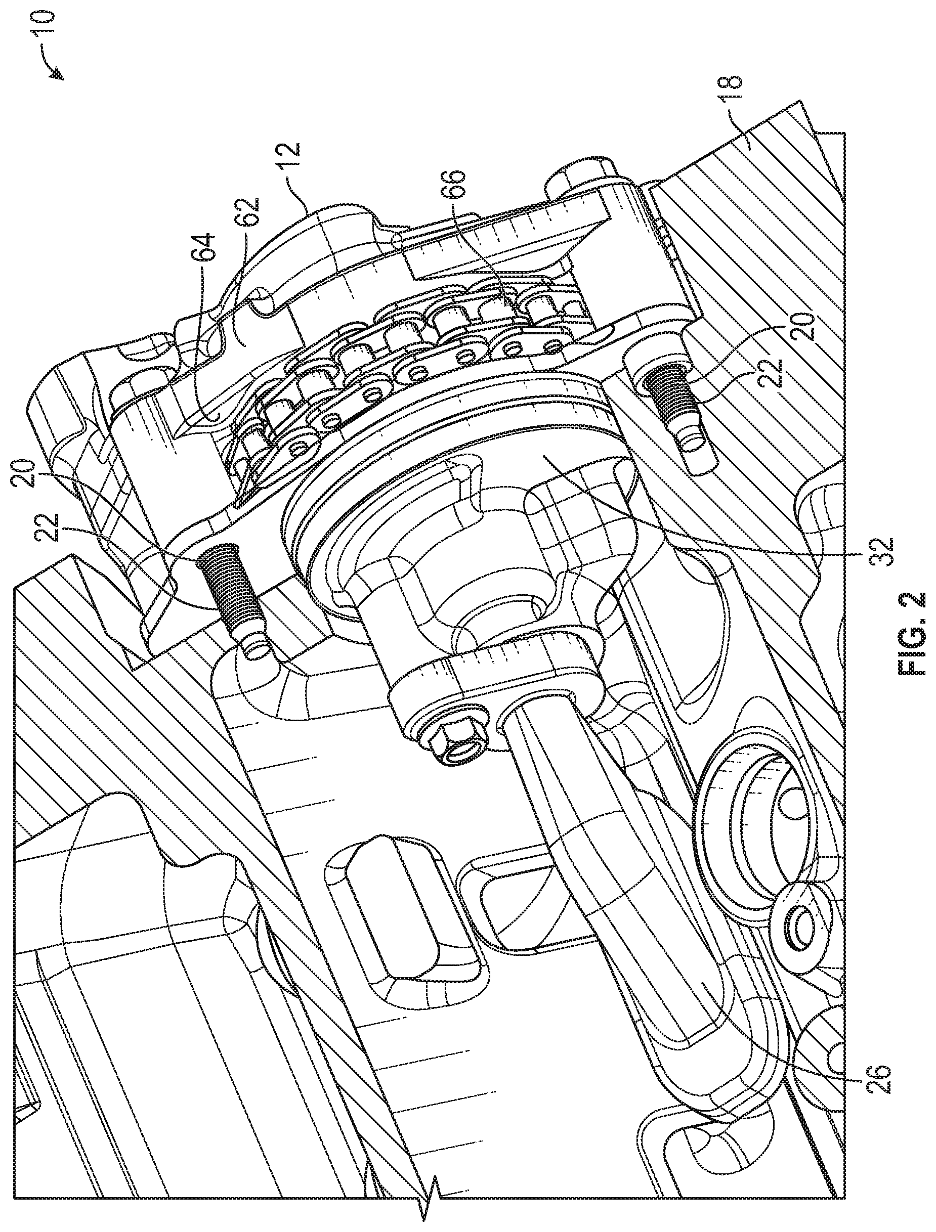
[0006] FIG. 2 is a schematic perspective sectional view of an engine block and the sprocket gerotor pump of FIG. 1.
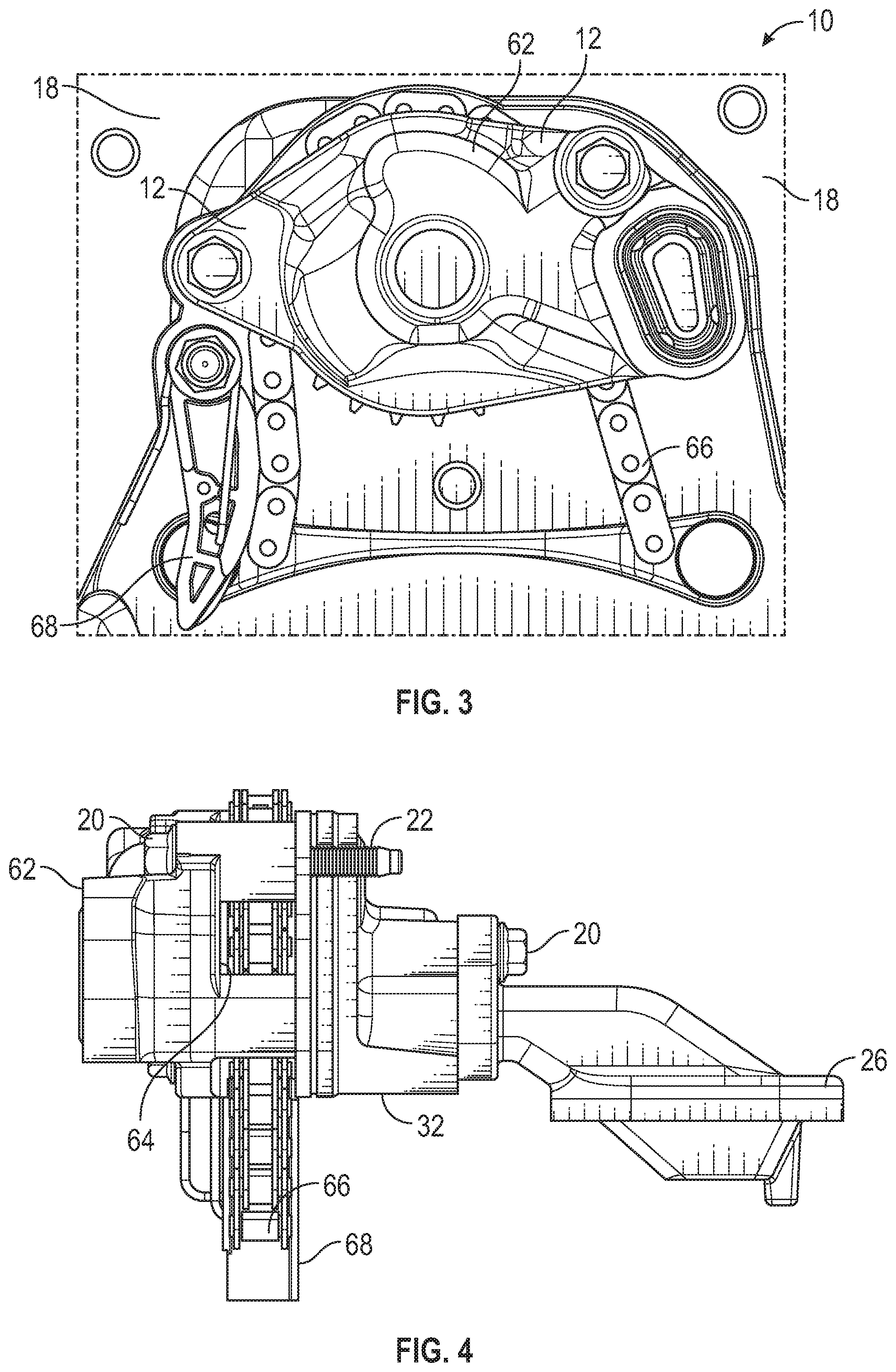
[0007] FIG. 3 is a schematic front view of the engine block and the sprocket gerotor pump of FIG. 1.
[0008] FIG. 4 is a schematic side view of the sprocket gerotor pump of FIG. 1.
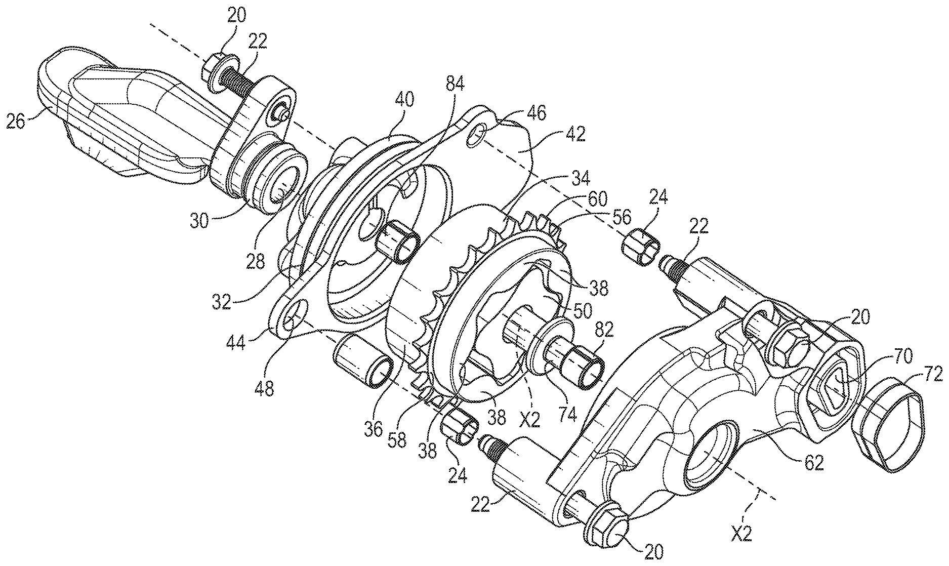
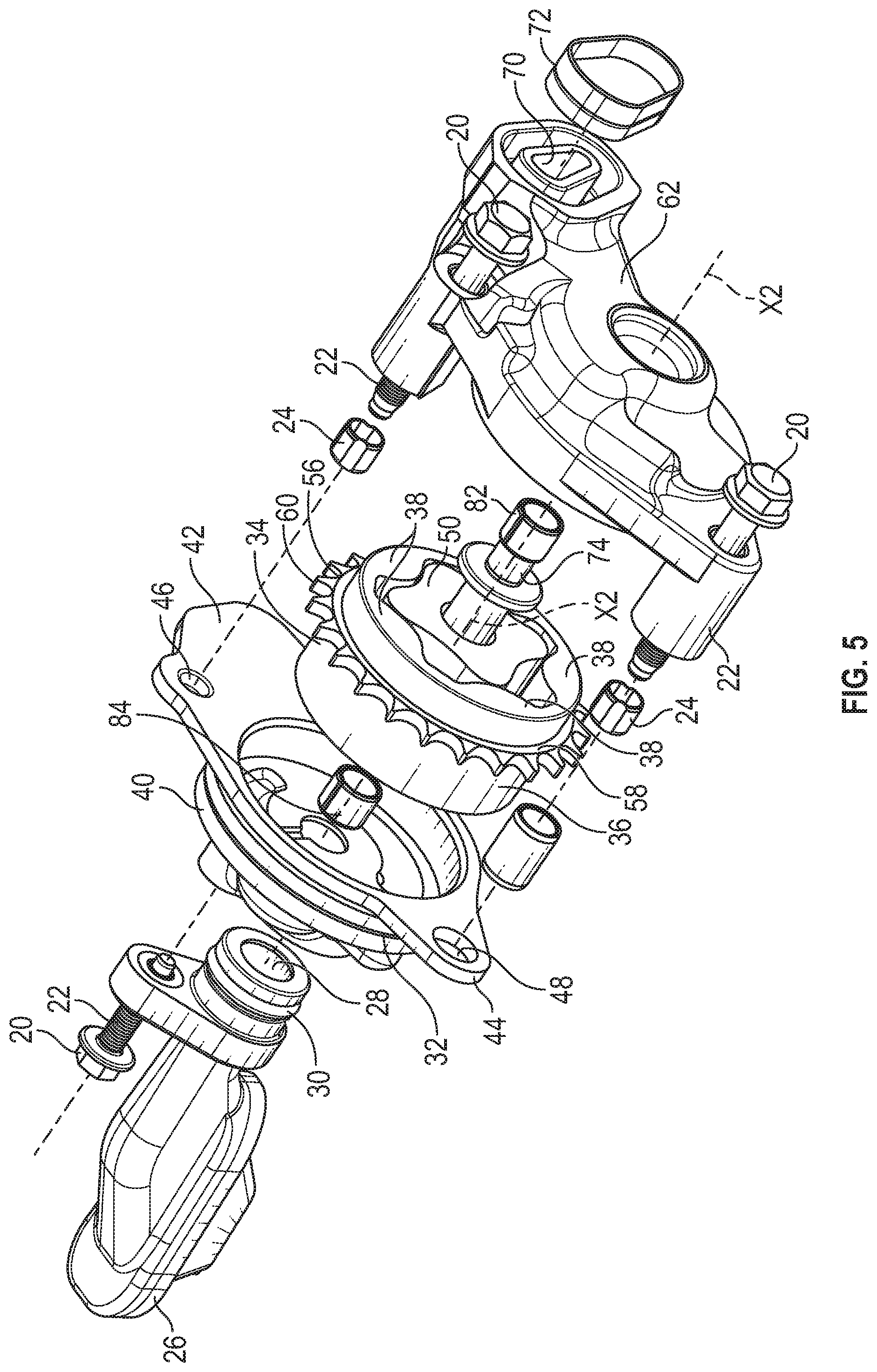
[0009] FIG. 5 is a schematic perspective, exploded view of the gerotor of FIG. 1.
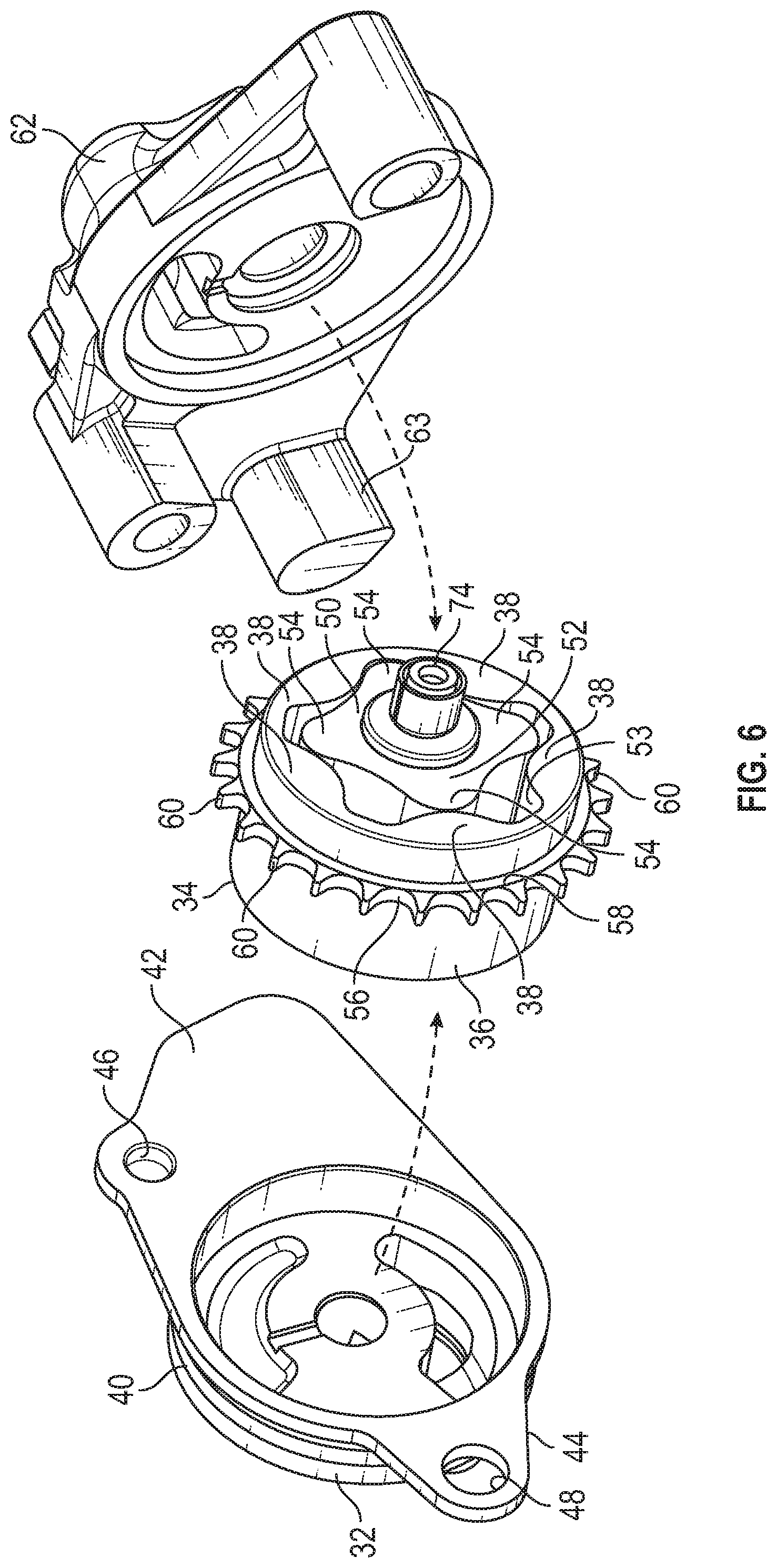
[0010] FIG. 6 is a schematic perspective, exploded view of a housing, a cover, an outer gerotor gear, a shaft, and an inner gerotor gear of the sprocket gerotor pump of FIG. 1.
[0011] FIG. 7 is a schematic sectional side view of the sprocket gerotor pump o FIG. 1.
DETAILED DESCRIPTION
[0012] With reference to FIG. 1, a vehicle system 10 includes a sprocket gerotor pump 12. The sprocket gerotor pump 12 may be configured as a supply pump 12 for moving a lubricant L (i.e., oil) to a vehicle component 13 and/or as a scavenge pump 12b for returning the lubricant L back to a lubricant source 16 (e.g., a storage reservoir). The vehicle system 10 may be a car, a truck, or other suitable device capable of transporting objects or passengers. In the depicted embodiment, the vehicle component 13 may be an internal combustion engine 14 having an engine block 18. Therefore, the sprocket gerotor pump 12 is in fluid communication with the vehicle component 13 (e.g., the internal combustion engine 14). The sprocket gerotor pump 12 is also in fluid communication with the lubricant source 16 (e.g., reservoir) containing the lubricant L (e.g., oil). Accordingly, the sprocket gerotor pump 12 may pump lubricant L from the lubricant source 16 to the vehicle component 13 (e.g., the internal combustion engine 14). Alternatively, the sprocket gerotor pump 12 may return from the vehicle component 13 back to the lubricant source 16.
[0013] With reference to FIGS. 2 and 4, one or more fasteners 20 directly connects the sprocket gerotor pump 12 to the engine block 18. In the depicted embodiment, the fasteners 20 are bolts 22 extending through the sprocket gerotor pump 12 and into the engine block 18 in order to directly couple the sprocket gerotor pump 12 to the engine block 18. Plastic bolt retainers 24 may be attached to each bolt 22 for retaining the bolts 22 in a fixed shipping position. The sprocket gerotor pump 12 is also supported by the engine block 18. For example, the engine block 18 may be in direct contact with the sprocket gerotor pump 12 to enhance their structural connection.
[0014] With reference to FIGS. 2-7, the sprocket gerotor pump 12 is a positive displacement pump including a pickup tube 26 in fluid communication with the lubricant in the engine cylinder head cavities. The pickup tube 26 defines a pickup channel 28 (FIG. 5) for allowing fluid flow of the lubricant L. An O-ring may be disposed around an annular portion 30 of the pickup tube 26 to avoid air suction. The sprocket gerotor pump 12 further includes an outer gerotor gear 34 and a housing 32 partially encasing the outer gerotor gear 34. One or more fasteners 20 (e.g., bolts 22) directly couples pickup tube 26 to the housing 32. The housing 32 further includes a housing body 40, a first housing flange 42 extending laterally from the housing body 40, and a second housing flange 44 extending laterally from the housing body 40. The housing 32 defines a first flange hole 46 extending through the first housing flange 42 and a second flange hole 48 extending through the second housing flange 44. Each of the first flange hole 46 and the second flange hole 48 is configured, sized, and shaped to receive one of the fasteners 20 (e.g., bolts 22).
[0015] As discussed above, the sprocket gerotor pump 12 includes the outer gerotor gear 34. Aside from being configured to rotate about the first axis X1, the outer gerotor gear 34 includes an outer gear body 36 including a plurality of internal gear teeth 38 extending from the outer gear body 36 toward the first axis X1.
[0016] The sprocket gerotor pump 12 further includes an inner gerotor gear 50 configured to rotate about a second axis X2. The first axis X1 of the outer gerotor gear 34 is spaced apart (and parallel to) the second axis X2 of the inner gerotor gear 50. In other words, the second axis X2 is offset from the first axis X1. The inner gerotor gear 50 includes an inner gear body 52 and a plurality of external gear teeth 54 extending from the inner gear body 52 away from the second axis X2. The external gear teeth 54 mesh with the internal gear teeth 38 of the outer gerotor gear 34. Consequently, rotating the outer gerotor gear 34 causes rotation of the inner gerotor gear 50. The internal gear teeth 38 defines an inner cavity 53. The inner cavity 53 is sized to receive the inner gerotor gear 50. Specifically, the inner gerotor gear 50 is entirely disposed inside the inner cavity 53. The inner gerotor gear 50 has n external gear teeth 54, while the outer gerotor gear 34 has n+1 internal gear teeth 38, wherein n is a natural number greater than 2. The geometry of the inner gerotor gear 50 and the outer gerotor gear 34 partitions the volume between them into n different dynamically-changing volumes. During rotation, each of these volumes defined between the internal gear teeth 38 and the external gear teeth 54 changes continuously (i.e., increasing and then decreasing). An increase in volume creates a vacuum. This vacuum in turn creates suction. Lubricant intake by the sprocket gerotor pump 12 occurs during suction. On the other hand, cavity compression occurs when the volume between the internal gear teeth 38 and the external gear teeth 54 decreases. During cavity 53 compression, the lubricant L is squeezed out of the sprocket gerotor pump 12.
[0017] The sprocket gerotor pump 12 further includes a sprocket 56 integrally coupled with the outer gerotor gear 34. As such, the sprocket 56 and the outer gerotor gear 34 collectively form a one-piece structure. The term "integrally coupled" means that components are part of a one-piece or unitary structure and excludes components that are interconnected by, for example, fasteners, welding, friction fitting, adhesives, or other attaching methods. The term "one-piece structure" means a structure made of a single undivided piece and excludes structures made of components that are interconnected by, for example, fasteners, welding, friction fitting, adhesives, or other attaching methods. By integrally coupling the sprocket 56 to the outer gerotor gear 34, the package size and the mass of the sprocket gerotor pump 12 is minimized. As a result, the additional package space is created in the vehicle system 10, allowing vehicle manufacturers to incorporate additional devices into the vehicle system 10. The sprocket 56 includes a ring 58 and a plurality of external sprocket teeth 60 extending from the ring 58. The ring 58 is directly coupled to the outer gear body 36. Specifically, the ring 58 is integrally coupled to the outer gear body 36 to minimize the package size of the sprocket gerotor pump 12 as discussed above. Each of the external sprocket teeth 60 is directly coupled to the ring 58. Specifically, each of the external sprocket teeth 60 is integrally coupled to the ring 58 to minimize the package size of the sprocket gerotor pump 12 as discussed above. Each of the external sprocket teeth 60 extends away from the first axis X1.
[0018] The sprocket gerotor pump 12 further includes a cover 62 partially encasing the outer gerotor gear 34. The housing 32 and the cover 62 collectively define an annular gap 64 therebetween. The sprocket gerotor pump 12 further includes a chain 66 partially disposed in the annular gap 64. One or more fasteners 20 (e.g., bolts 22) couple the cover 62 to the housing 32 while maintaining the annular gap 64 between the cover 62 and the housing 32. In the case of the supply pump 12a, the cover 62 defines an outlet 70 to deliver lubricant L to the vehicle component 13. In the case of the scavenge pump 12b, the cover 62 defines an outlet 70 to deliver lubricant L to the lubricant source 16. One or more seals 72 are coupled to the outlet 70 to minimize lubricant leakage. Another sprocket (that is not part of the meshed sprocket gerotor pump 12) is connected to a crankshaft and drives the chain 66 to rotate the outer gerotor gear 34. The chain 66 meshes with the external sprocket teeth 60. Thus, rotating the chain 66 causes the outer gerotor gear 34 to rotate. The annular gap 64 solely receives the external sprocket teeth 60 and a portion of the chain 66 to minimize the space occupied by the sprocket gerotor pump 12. A chain tensioner 68 may be coupled to the engine block 18 to maintain the chain 66 in tension. Accordingly, the chain tensioner 68 is configured to be in direct contact with the chain 66. The housing 62 includes a support feature 63 (e.g., protrusion) that is on the same plane with other two bases to support the housing 40 to absorb vibration and structural load.
[0019] The sprocket gerotor pump 12 further includes a shaft 74 extending through the cover 62, the housing 32, and the inner gerotor gear 50. Accordingly, the shaft 74 interconnects and supports the cover 62, the housing 32, and the inner gerotor gear 50. The shaft 74 includes a first end portion 76 (FIG. 7) and a second end portion 78 (FIG. 8) spaced apart from the first end portion 76 along the second axis X2. Further, the shaft 74 includes a thrust face/bearing face 80. The shaft flange 80 is closer to the first end portion 76 than to the second end portion 78 of the shaft 74. The sprocket gerotor pump 12 includes a first bushing 82 and a second bushing 84. The first bushing 82 is coupled to the first end portion 76, and the second bushing 84 is coupled to the second end portion 78 of the shaft 74. The chain 66 is located in the annular gap 64 between the first bushing 82 and the second bushing 84 to evenly distribute the load exerted by the chain 66, thereby maximizing shared stress load on the shaft 74 and the bearings 84 and 76.
[0020] While the best modes for carrying out the disclosure have been described in detail, those familiar with the art to which this disclosure relates will recognize various alternative designs and embodiments for practicing the disclosure within the scope of the appended claims.
* * * * *
D00000
D00001
D00002
D00003
D00004
D00005
D00006
XML
uspto.report is an independent third-party trademark research tool that is not affiliated, endorsed, or sponsored by the United States Patent and Trademark Office (USPTO) or any other governmental organization. The information provided by uspto.report is based on publicly available data at the time of writing and is intended for informational purposes only.
While we strive to provide accurate and up-to-date information, we do not guarantee the accuracy, completeness, reliability, or suitability of the information displayed on this site. The use of this site is at your own risk. Any reliance you place on such information is therefore strictly at your own risk.
All official trademark data, including owner information, should be verified by visiting the official USPTO website at www.uspto.gov. This site is not intended to replace professional legal advice and should not be used as a substitute for consulting with a legal professional who is knowledgeable about trademark law.