Module Of A Variable Valve Drive Of An Internal Combustion Engine
Schmidt; Volker ; et al.
U.S. patent application number 16/441486 was filed with the patent office on 2020-01-23 for module of a variable valve drive of an internal combustion engine. This patent application is currently assigned to Schaeffler Technologies AG & Co. KG. The applicant listed for this patent is Schaeffler Technologies AG & Co. KG. Invention is credited to Wolfgang Christgen, Volker Schmidt.
| Application Number | 20200025043 16/441486 |
| Document ID | / |
| Family ID | 69147822 |
| Filed Date | 2020-01-23 |
| United States Patent Application | 20200025043 |
| Kind Code | A1 |
| Schmidt; Volker ; et al. | January 23, 2020 |
MODULE OF A VARIABLE VALVE DRIVE OF AN INTERNAL COMBUSTION ENGINE
Abstract
A module of a variable valve drive of an internal combustion engine is proposed that includes a push rod mounted longitudinally in a cylinder head of the internal combustion engine. The push rod is actuated by a linear actuator that includes an armature that makes contact, at least indirectly with the push rod, to displace it in a first longitudinal direction. A switchable rocker arm with a coupling slide arranged transversely to a longitudinal extent or side of the rocker arm corresponds to an actuating finger that extends from the push rod. The coupling slide includes a slide part that projects laterally from the rocker arm and can be acted upon by a free end of the actuating finger. Kinetic energy of the push rod is dissipated or converted at least partially via a separate damper in the first longitudinal direction before it reaches a final position.
| Inventors: | Schmidt; Volker; (Burgbernheim, DE) ; Christgen; Wolfgang; (Seukendorf, DE) | ||||||||||
| Applicant: |
|
||||||||||
|---|---|---|---|---|---|---|---|---|---|---|---|
| Assignee: | Schaeffler Technologies AG &
Co. KG Herzogenaurach DE |
||||||||||
| Family ID: | 69147822 | ||||||||||
| Appl. No.: | 16/441486 | ||||||||||
| Filed: | June 14, 2019 |
| Current U.S. Class: | 1/1 |
| Current CPC Class: | F01L 1/185 20130101; F01L 2820/03 20130101; F01L 1/46 20130101; F01L 1/22 20130101; F01L 2001/186 20130101; F01L 13/0005 20130101; F01L 2305/00 20200501; F01L 1/267 20130101 |
| International Class: | F01L 1/22 20060101 F01L001/22; F01L 1/18 20060101 F01L001/18; F01L 1/46 20060101 F01L001/46 |
Foreign Application Data
| Date | Code | Application Number |
|---|---|---|
| Jul 18, 2018 | DE | 10 2018 117 338.5 |
Claims
1. A module of a variable valve drive of an internal combustion engine, comprising a push rod configured to be mounted longitudinally in a cylinder head of the internal combustion engine, the push rod having an actuating finger; a linear actuator having an armature, the armature configured to displace the push rod in a first longitudinal direction; a switchable rocker arm having a coupling slide arranged transversely to a longitudinal side of the switchable rocker arm, the coupling slide arranged to be actuated by the actuating finger; and as the push rod is displaced by the linear actuator, kinetic energy of the push rod is dissipated at least partially by a damper.
2. The module as claimed in claim 1, wherein an electronic actuator is applied as the linear actuator.
3. The module as claimed in claim 1, wherein the damper acts upon the push rod before the push rod reaches a final position configured as a stop on the cylinder head.
4. The module as claimed in claim 1, wherein the damper dissipates kinetic energy of the push rod as the push rod moves in the first longitudinal direction.
5. The module as claimed in claim 1, wherein the damper dissipates kinetic energy of the push rod as the push rod moves in a second longitudinal direction, opposite the first longitudinal direction.
6. The module as claimed in claim 1, wherein the damper is attached to an end of the push rod.
7. The module as claimed in claim 1, further comprising the cylinder head, and the damper is configured within the cylinder head.
8. The module as claimed in claim 1, wherein a reverse position of the push rod is accomplished in a second longitudinal direction by a compression spring configured to be tensioned between the push rod and the cylinder head.
9. The module as claimed in claim 8, wherein the damper and compression spring are either combined in an assembly or are each spatially separate.
10. The module as claimed in claim 1, wherein the damper is one of either an elastic solid body, a gas damper, or a fluid damper.
11. The module as claimed in claim 1, wherein the actuating fingers are leaf-like spring tongues.
12. An actuation system for a variable valve drive of an internal combustion engine, comprising: a push rod configured to be mounted longitudinally in a cylinder head of the internal combustion engine, the push rod having at least one actuating finger configured to actuate a coupling slide of at least one switchable rocker arm; a linear actuator having an armature, the armature configured to displace the push rod; and as the push rod is displaced by the linear actuator, at least a portion of the kinetic energy of the push rod is dissipated by a damper.
13. The actuation system of claim 12, wherein the damper is a hydraulic clearance compensation element.
14. The actuation system of claim 12, further comprising the at least one switchable rocker arm, wherein the coupling slide of the at least one switchable rocker arm is arranged transversely to a longitudinal side of the switchable rocker arm.
15. The actuation system of claim 14, wherein the at least one switchable rocker arm includes a first and a second switchable rocker arm, and the at least one actuating finger includes a first and a second actuating finger, the first actuating finger arranged to actuate the first switchable rocker arm and the second actuating finger arranged to actuate the second switchable rocker arm.
16. The actuation system of claim 15, wherein displacement of the push rod in a first longitudinal direction by the linear actuator causes synchronous coupling or synchronous uncoupling of the first and second switchable rocker arms.
17. The actuation system of claim 15, wherein the first and second actuating fingers are leaf-like spring tongues that extend from the push rod.
18. The actuation system of claim 12, wherein the damper dissipates kinetic energy of the push rod as the push rod is displaced in a first longitudinal direction by the linear actuator.
19. The actuation system of claim 12, further comprising a spring that is arranged to move the push rod in a second longitudinal direction.
20. The actuation system of claim 19, wherein the damper dissipated kinetic energy of the push rod as it moves in the second longitudinal direction.
Description
CROSS-REFERENCE TO RELATED APPLICATIONS
[0001] This application claims priority under 35 U.S.C. Section 119 of German Patent Application No. DE 2018 117 338.5 filed Jul. 18, 2018, the disclosure of which is incorporated herein by reference.
TECHNICAL FIELD
[0002] This disclosure relates to a module of a variable valve drive of an internal combustion engine. The module includes a push rod mounted longitudinally in a cylinder head of the internal combustion engine. The push rod is actuated by a linear actuator that includes an armature that makes contact, at least indirectly, with the push rod to displace it in a longitudinal direction. A switchable rocker arm with a coupling slide arranged transversely to the longitudinal extent or side of said rocker arm corresponds to an actuating finger that extends from the push rod. The coupling slide includes a slide part that projects laterally from the rocker arm and can be acted upon by a free end of the actuating finger.
BACKGROUND
[0003] Modules of this kind with a push rod acted upon by an actuator, actuator fingers thereon, and rocker arms, are now also referred to as electronic rocker modules or systems. One example of this emerges from DE 10 2017 101 792. In this case, a series of identically operating gas exchange valves in a series of cylinders in an internal combustion engine in the cylinder head is each assigned a rocker arm with an actuator on the front end, in this case an electronic actuator. Two identically operating gas exchange valves are provided for each cylinder. A reset of the push rod takes place when the actuator is not energized through the force of a servo means, in this case a compression spring.
[0004] The disadvantage of the aforementioned embodiment is that the push rod emits structure-borne noise when one of its two final positions is suddenly reached. These frequencies may lie within an audible, and thus, within a comfort range. A "hard" stop of the cylinder head (body edge) is a potential end point/reverse point for the push rod in an actuator extension direction. In the return direction thereof, either a counter-stop of this kind or a stop for the armature of the actuator in said actuator is conceivable and provided for. Depending on the embodiment of the actuator armature/push rod assembly, said push rod may also become detached from the armature when it is suddenly slowed down by a stop and strike it while once again emitting noises.
[0005] The problem is that of creating a module of the aforementioned kind which can be operated in a low-noise manner.
SUMMARY
[0006] According to the disclosure, this problem is solved in that the kinetic energy of the push rod, which may be a flat metal sheet, a pipe or a solid cylinder, is dissipated at least partially via a separate damper before it reaches its final position, at least in a first longitudinal direction away from the linear actuator. A damper according to one embodiment of the disclosure, can be an elastic solid body (elastomer, plastic, rubber), a gas damper, or a fluid damper.
[0007] In the simplest variant, a rubber piece, for example, is therefore attached to the push rod on the free end face thereof, through which the kinetic energy of the push rod is "abolished" or, to be more precise, dissipated or converted, in the extension and impact scenario brought about by the actuator, so that the push rod reaches its final position comparatively "gently" and without emitting audible noises. The damper may also lie on the counter-contour of the cylinder head. Likewise, the other rearward end point in the actuator may be provided with a mechanical damper or this final position may likewise be "damped" by the aforementioned measures on the push rod or the cylinder head. Where necessary, dampers such as elastic solid bodies may also be attached to each of the contours (push rod and cylinder head) in one or both abutment cases.
[0008] An alternative would be a gas or fluid damper. Both dampers may have a substantially progressive characteristic curve, so that it is also possible for them to be permanently connected to the push rod, at least in the extension direction thereof. A fluid damper should also be understood to mean a leakage gap element, for example, as is known from valve drive technology as a hydraulic clearance compensation element which are also fitted into chain or belt tensioners.
[0009] According to a further development of the disclosure, the push rod, wherein a set of push rods is also always possible, is to be acted upon in its reverse direction by a mechanical spring. At least one helical compression spring, in particular, is envisaged in this case, said helical compression spring being supported by the cylinder head at one end. As an alternative to this, the push rod may also be acted upon in the reverse position thereof via an actuator, such as an electronic actuator.
[0010] Instead of the free end face of the push rod contacting the damper, an arm which communicates with a damper of the cylinder head or itself possesses a damper for what is then a "hard" cylinder head contact may also project from the push rod.
[0011] It is also advantageous for the damping and compression spring to be combined in a pre-mounted assembly. However, where there are installation space problems, the separate application thereof is however also a possibility.
[0012] The actuating fingers projecting from the push rod are configured as leaf-like spring tongues according to one embodiment of the disclosure, but they may also be "stiff" fingers under certain circumstances.
BRIEF DESCRIPTION OF THE DRAWINGS
[0013] In relation to the drawings:
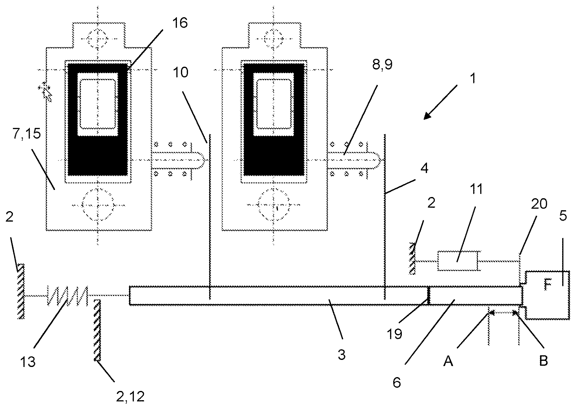
[0014] FIG. 1 shows a first variant of a module with a damper and spring existing separately from one another; and
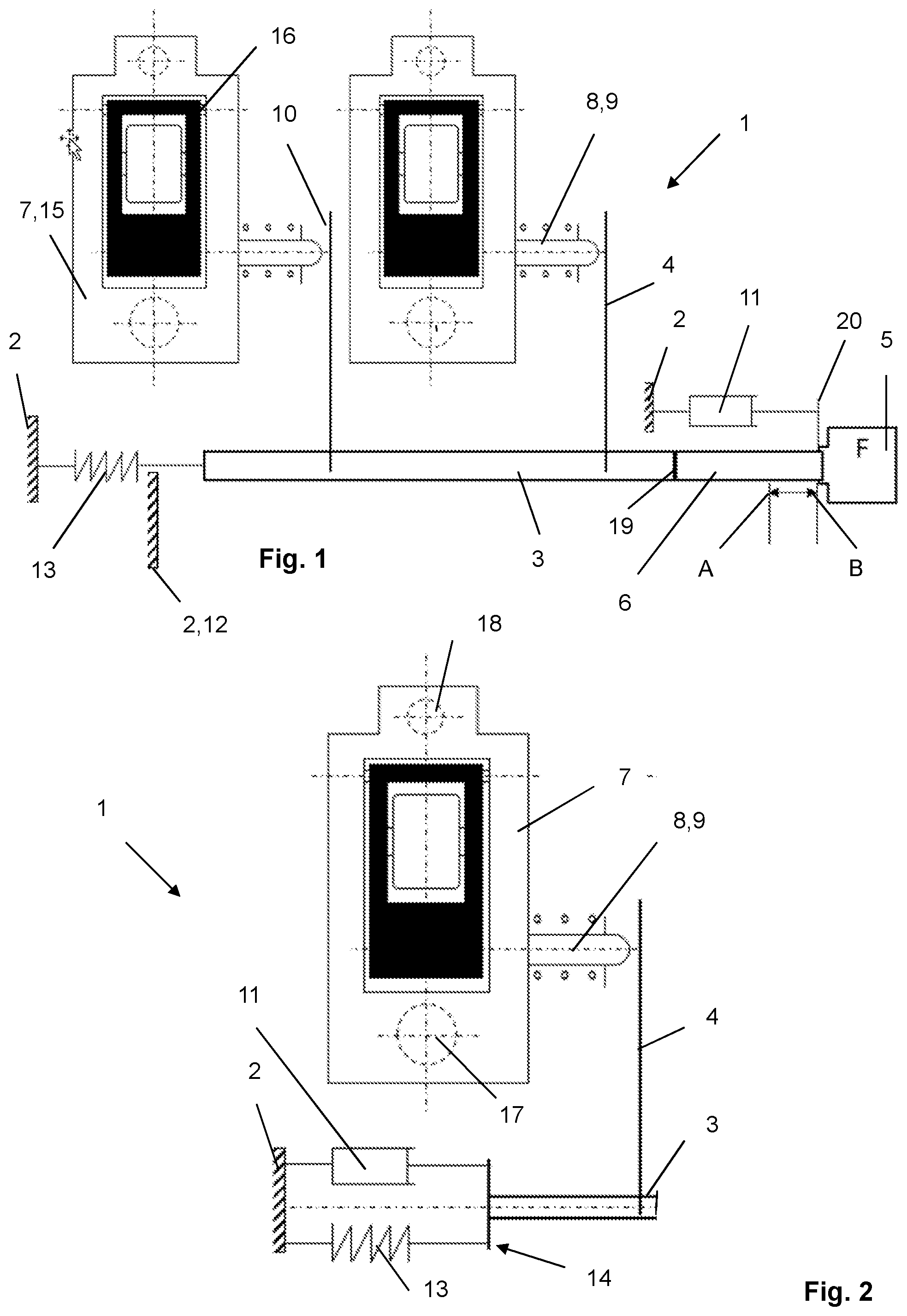
[0015] FIG. 2 shows a partial view as previously mentioned, wherein a damper and spring form a structural unit.
DETAILED DESCRIPTION
[0016] FIGS. 1, 2 show a module 1 of a variable valve drive of an internal combustion engine. This module 1 is also referred to as an electronic rocker module or system.
[0017] Module 1 comprises a push rod 3 mounted longitudinally in a cylinder head 2 of the internal combustion engine. An actuating finger 4 configured as a leaf-like spring tongue is suspended from said push rod for each switchable rocker arm 7 to be actuated. The push rod 3, as disclosed in FIG. 1, is preceded by a linear actuator 5 configured as an electronic actuator (electronic magnet). The push rod includes a face 19 on a right end that is aligned with the linear actuator 5. An armature 6 of the linear actuator 5 acts directly on the aforementioned face 19 to displace the push rod 3 in the first longitudinal direction A.
[0018] Each actuating finger 4 cooperates with a switchable rocker arm 7 as a further component of the module. The rocker arm 7 comprises in each case, although this need not be further dealt with here, a box-like outer lever 15 which encloses an inner lever 16. On an underside (facing away from a camshaft) the rocker arm 7 has a support 17 for pivotable mounting on a support element on one longitudinal end and a valve contact 18 on another longitudinal end.
[0019] There projects laterally from each rocker arm 7 being switched a coupling slide means 8 which therefore runs transversely and which, in the simplest case, comprises precisely one slide part 9, wherein, however, two or three slide parts can be provided. The slide part 9, as emerges from the two figures, is acted upon by a free end 10 of its actuating finger 4. In this case, the actuating fingers 4 in both figures are depicted out of contact with their slide parts 9, which represents an unswitched state of the module 1. Where necessary, the aforementioned components may also be in contact in this state.
[0020] So that all identically operating rocker arms 7 are synchronously coupled (or, alternatively, uncoupled), the electronic actuator 5 is energized, as a result of which the armature 6 thereof displaces the push rod 3 in both figures, in this case from right to left against the force of a compression spring 13. The bendable actuating fingers 4 are pretensioned on their slide parts 9, which slide parts 9 can then be suddenly displaced when the cam base circle is passed through. According to FIG. 1, the push rod 3 experiences a final travel limit at a "hard" stop 12. Said stop is a simple body edge on the cylinder head 2.
[0021] According to FIG. 1, a damper 11 is provided on the module 1 which is spatially separate from the compression spring 13. This is only depicted as a symbol here and, in the simplest case, comprises a simple elastic solid body. From the push rod 3 which represents a structural unit with the armature 6 here, there projects away an arm 20 connected thereto which, when the armature 6 moves with the push rod 3 in the first longitudinal direction A, comes into contact with the damper 11 or is in contact from the very beginning.
[0022] Through this embodiment, the push rod 3 experiences at its one final position no sudden braking accompanied by noises and increased wear. Instead, at least some of the kinetic energy of the push rod 3 is converted in the damper 11 or dissipated by the damper 11.
[0023] If the electronic actuator 5 is de-energized, a backwards displacement of the push rod 3 takes place in a second longitudinal direction B via the compression spring 13 with simultaneous "removal" of the actuator fingers 4 from their slide parts 9. The aforementioned fingers are acted upon in their respective rocker arm 7 via spring means which are not labelled in the extension direction (to the right in the case) and when the cam base circle is passed through they are suddenly displaced outwards, as depicted.
[0024] It is provided according to FIG. 2 for the damper 11 and compression spring 13 to be combined in an assembly 14.
LIST OF REFERENCE CHARACTERS
[0025] 1 Module [0026] 2 Cylinder head [0027] 3 Push rod [0028] 4 Actuating finger [0029] 5 Linear actuator, electronic actuator [0030] 6 Armature [0031] 7 Rocker arm [0032] 8 Coupling slide [0033] 9 Slide part [0034] 10 End [0035] 11 Damper [0036] 12 Stop [0037] 13 Compression spring [0038] 14 Assembly [0039] 15 Outer lever [0040] 16 Inner lever [0041] 17 Support [0042] 18 Valve contact [0043] 19 Face [0044] 20 Arm [0045] A first longitudinal direction [0046] B second longitudinal direction
* * * * *
D00000
D00001
XML
uspto.report is an independent third-party trademark research tool that is not affiliated, endorsed, or sponsored by the United States Patent and Trademark Office (USPTO) or any other governmental organization. The information provided by uspto.report is based on publicly available data at the time of writing and is intended for informational purposes only.
While we strive to provide accurate and up-to-date information, we do not guarantee the accuracy, completeness, reliability, or suitability of the information displayed on this site. The use of this site is at your own risk. Any reliance you place on such information is therefore strictly at your own risk.
All official trademark data, including owner information, should be verified by visiting the official USPTO website at www.uspto.gov. This site is not intended to replace professional legal advice and should not be used as a substitute for consulting with a legal professional who is knowledgeable about trademark law.