Combined Processing Method for Lithium Containing Solutions
REED; Christopher John
U.S. patent application number 16/483774 was filed with the patent office on 2020-01-23 for combined processing method for lithium containing solutions. The applicant listed for this patent is Inneovation Pty Ltd. Invention is credited to Christopher John REED.
| Application Number | 20200024686 16/483774 |
| Document ID | / |
| Family ID | 63106802 |
| Filed Date | 2020-01-23 |


View All Diagrams
| United States Patent Application | 20200024686 |
| Kind Code | A1 |
| REED; Christopher John | January 23, 2020 |
Combined Processing Method for Lithium Containing Solutions
Abstract
A combined processing method for the purification of lithium containing solutions, the method comprising the method steps of passing a lithium containing solution to a first purification step in which the lithium containing solution is contacted with a titanate adsorbent whereby lithium ions are adsorbed thereon whilst rejecting substantially all other cations, the recovery of lithium from the adsorbent providing a part-purified lithium containing solution, the part-purified lithium containing solution produced in the first purification step is then passed in whole or part to a second purification step in which a graphene based filter medium is utilised to provide a further purified lithium containing solution.
| Inventors: | REED; Christopher John; (Swanbourne, AU) | ||||||||||
| Applicant: |
|
||||||||||
|---|---|---|---|---|---|---|---|---|---|---|---|
| Family ID: | 63106802 | ||||||||||
| Appl. No.: | 16/483774 | ||||||||||
| Filed: | February 8, 2017 | ||||||||||
| PCT Filed: | February 8, 2017 | ||||||||||
| PCT NO: | PCT/AU2017/050099 | ||||||||||
| 371 Date: | August 6, 2019 |
| Current U.S. Class: | 1/1 |
| Current CPC Class: | C01G 23/005 20130101; C01G 23/003 20130101; C01P 2006/12 20130101; C01P 2004/04 20130101; C01P 2004/13 20130101; C22B 3/20 20130101; C22B 26/12 20130101; C01D 15/04 20130101; C01P 2006/80 20130101; C22B 3/24 20130101; Y02P 10/234 20151101; B01J 20/06 20130101 |
| International Class: | C22B 26/12 20060101 C22B026/12; C01D 15/04 20060101 C01D015/04; C01G 23/00 20060101 C01G023/00; C22B 3/24 20060101 C22B003/24 |
Claims
1-41. (canceled)
42. A combined processing method for the purification of lithium containing solutions, the method comprising the method steps of passing a lithium containing solution to a first purification step in which the lithium containing solution is contacted with a titanate adsorbent whereby lithium ions are adsorbed thereon whilst rejecting substantially all other cations, the recovery of lithium from the adsorbent providing a part-purified lithium containing solution, the part-purified lithium containing solution produced in the first purification step is then passed in whole or part to a second purification step in which a graphene based filter medium is utilised to provide a further purified lithium containing solution.
43. The method of claim 42, wherein the lithium containing solution is a lithium containing brine.
44. The method of claim 42, wherein the adsorbent is provided in the form of either a hydrated titanium dioxide or a sodium titanate.
45. The method of claim 42, wherein the further purified lithium containing solution is a substantially pure lithium chloride solution.
46. The method of claim 42, wherein the brine contains impurities from the group of sodium, potassium, magnesium, calcium and borate, and the impurity concentration does not exceed about 20 ppm.
47. The method of claim 43, wherein the brine contains lithium in the range of about 500 to 1500 ppm, and impurities including magnesium in the range of about 0.15% to 0.30%, calcium in the range of about 0.05% to 0.1%, sodium in the range of about 8 to 10%, potassium in the range of about 0.7% to 1.0%, and borate in the range of about 0.15% to 0.20%.
48. The method of claim 43, wherein the brine solution is adjusted to a pH of 7 through the addition of a base.
49. The method of claim 42, wherein the contact between the lithium containing solution and the adsorbent takes place at or about room or ambient temperature.
50. The method of claim 49, wherein the contact or residence time between the brine solution and the adsorbent is: a) between about 4 to 24 hours; b) between about 20 to 24 hours; or c) between about 8 to 16 hours.
51. The method of claim 42, wherein the recovery of lithium from the adsorbent is achieved through the regeneration of the adsorbent by the addition of an acid solution and the adsorbed lithium is extracted to provide the part purified lithium containing solution.
52. The method of claim 51, wherein the acid solution is a solution of hydrochloric acid.
53. The method of claim 51, wherein the amount of lithium extracted from the adsorbent through exposure to the acid solution is: a. greater than about 90%; or b. about 100%.
54. The method of claim 42, wherein the graphene based filter medium of the second purification step comprises a graphene membrane formed of one or more graphene, graphene oxide and/or reduced graphene oxide and to which the part-purified lithium containing solution is presented.
55. The method of claim 54, wherein the passing of the part purified lithium containing solution to the second purification step produces a filtrate or permeate that is enriched in relative terms in lithium ions, providing the further purified lithium containing solution.
56. The method of claim 54, wherein the second purification step is conducted under pressure.
57. The method of claim 42, wherein the further purified lithium containing solution is suitable is suitable for use in the production of battery grade lithium chemicals.
58. The method of claim 42, wherein the graphene is provided as a graphene oxide membrane formed in turn from graphite oxide powder.
59. The method of claim 54, wherein the graphene oxide membrane is reduced by way of exposure to ascorbic acid.
60. The method of claim 54, wherein the membrane is supported by a porous substrate.
61. The method of claim 54, wherein the graphene membrane has a thickness of between: c. 30 to 200 nm; or d. 150 to 200 nm.
62. The method of claim 42, wherein the level of salt rejection achieved by the second purification step is 20% or greater as measured by the conductivity of a permeate relative to that of the part-purified lithium containing solution.
63. The method of claim 62, wherein lithium is the least rejected ion or salt of the second purification step.
64. The method of claim 1, wherein the first and second purification steps comprise one or more stages, passes or repeats of contact or exposure between the lithium containing solution passed to them and the adsorbent or filter medium, respectively.
Description
FIELD OF THE INVENTION
[0001] The present invention relates to a combined processing method for lithium containing solutions.
[0002] More particularly, the method of the present invention is intended for use in the extraction of lithium chloride from a lithium containing brine. In one form the extraction of lithium chloride from a lithium containing brine is achieved through the combined action of an adsorbent and a filter utilising a graphene based filter medium.
[0003] The present invention further relates to the synthesis of an adsorbent derived from titanium dioxide, such as sodium titanate (Na.sub.2Ti.sub.3O.sub.7) or hydrogen titanate (H.sub.2TiO.sub.3), and a process for the extraction of lithium chloride from a lithium containing solution, such as a brine, from such adsorbent. More particularly, the lithium chloride is extracted from a brine solution through adsorption on an adsorbent, for example sodium titanate (Na.sub.2Ti.sub.3O.sub.7) or hydrogen titanate (H.sub.2TiO.sub.3), synthesised from titanium dioxide.
[0004] The present invention still further relates to a process for the purification of semi-pure lithium chloride obtained through adsorption of lithium on an adsorbent, such as sodium titanate or hydrogen titanate, to prepare high purity lithium chloride solution for use in battery applications. This is particularly achieved through a process in which the semi-pure lithium chloride solution obtained through desorption on adsorbent is passed through a graphene based membrane.
[0005] The graphene based filter medium employed in the process of the present invention is particularly, in one form, graphene oxide (GO) or reduced graphene oxide (rGO). It is envisaged that the graphene based filter medium acts as an ion sieve, allowing ions with smaller sizes than those of the channels to permeate while blocking all other larger species. In this manner it is understood that the graphene based filter medium rejects impurities such as K, Na and Mg, allowing the purification of a LiCl containing solution.
Background Art
[0006] Lithium chloride (LiCl) has widespread commercial application. It is used in the production of lithium metal, lithium carbonate and lithium hydroxide monohydrate for various battery applications. Due to the requirement for high purity in many of these applications, particularly when used as a cathode material in lithium ion batteries, there is an ever increasing need for high purity lithium chloride.
[0007] Traditionally, LiCl from a brine source is purified by solar evaporation technology to concentrate the brine solution and thereby remove sodium and potassium impurities. Other impurities, such as boron, may be removed by solvent extraction technology, whereas calcium, magnesium and other similar impurities may be removed by increasing the pH of the brine solution. This is typically achieved through the addition of lime and the formation and precipitation of insoluble salts, including calcium carbonate. This is very time consuming and highly dependent on the weather. Therefore, a purification means is needed to remove the majority of the impurities from a LiCl solution derived from a brine source, such that the concentration of each impurity is reduced to less than about 20 ppm.
[0008] An impurity concentration of less than about 20 ppm makes the resulting LiCl solution suitable for use in lithium metal extraction or the preparation of other lithium compounds, including lithium carbonate and lithium hydroxide monohydrate, for use in lithium ion battery applications.
[0009] The processes of the present invention have as one object thereof to overcome substantially one or more of the above mentioned problems associated with prior art, or to at least provide a useful alternative thereto.
[0010] The preceding discussion of the background art is intended to facilitate an understanding of the present invention only. This discussion is not an acknowledgement or admission that any of the material referred to is or was part of the common general knowledge as at the priority date of the application.
[0011] Throughout the specification and claims, unless the context requires otherwise, the word "comprise" or variations such as "comprises" or "comprising", will be understood to imply the inclusion of a stated integer or group of integers but not the exclusion of any other integer or group of integers.
[0012] The term brine, or brines, or variations thereof, is to be understood to include a solution of alkali and/or alkaline earth metal salt(s) in water, of a natural or possibly industrial source. The concentrations of the various salts can vary widely. The ions present in brine may include a combination of one or more of a monovalent cation, such as lithium, multivalent cations, monovalent anions, and multivalent anions.
[0013] The term high purity lithium chloride is to be understood, unless the context requires otherwise, as requiring any impurity present to be present in amounts of less than about 20 ppm.
[0014] The term graphene, graphene sheet or graphene material is to be understood, unless the context requires otherwise, as including single layer graphene, few layer graphene (FLG), graphene nano-platelets, graphene nanotubes, graphene nanoribbons, graphene nano-sheets and the like.
DISCLOSURE OF THE INVENTION
[0015] In accordance with the present invention there is provided a combined processing method for the purification of lithium containing solutions, the method comprising the method steps of passing a lithium containing solution to a first purification step in which the lithium containing solution is contacted with a titanate adsorbent whereby lithium ions are adsorbed thereon whilst rejecting substantially all other cations, the recovery of the lithium from the adsorbent providing a part-purified lithium containing solution, the part-purified lithium containing solution produced in the first purification step is then passed in whole or part to a second purification step in which a graphene based filter medium is utilised to provide a further purified lithium containing solution.
[0016] In one form, the lithium containing solution is a lithium containing brine.
[0017] Preferably, the adsorbent is provided in the form of either a hydrated titanium dioxide or a sodium titanate. In one form of the present invention the hydrated titanium dioxide is produced from titanium dioxide.
[0018] Still preferably, the process in turn produces a substantially pure lithium chloride solution.
[0019] The brine preferably contains impurities from the group of sodium, potassium, magnesium, calcium and borate.
[0020] Still preferably, the impurity concentration of the substantially pure lithium chloride solution does not exceed about 20 ppm.
[0021] In one form of the present invention the brine contains lithium in the range of about 500 to 1500 ppm, and impurities including magnesium in the range of about 0.15% to 0.30%, calcium in the range of about 0.05% to 0.1%, sodium in the range of about 8 to 10%, potassium in the range of about 0.7% to 1.0%, and borate in the range of about 0.15% to 0.20%.
[0022] In a more preferred form of the present invention, the brine contains about 700 ppm lithium, about 0.19% magnesium, about 0.09% calcium, about 8.8% sodium, about 0.8% potassium and about 0.18% borate.
[0023] The brine solution is preferably adjusted to a pH of 7 through the addition of a base. The base is preferably provided in the form of sodium hydroxide.
[0024] The contact between the brine solution and the adsorbent preferably takes place at or about room or ambient temperature.
[0025] In one form of the present invention the brine is collected into a vessel and cooled to room temperature prior to its exposure to the adsorbent. Preferably, room temperature is understood to be between about 20.degree. C. to 28.degree. C.
[0026] Preferably, the contact or residence time between the brine solution and the adsorbent is between about 4 to 24 hours.
[0027] Still preferably, the contact or residence time between the brine solution and the adsorbent is: [0028] a) between about 8 to 24 hours; [0029] b) between about 20 to 24 hours; or [0030] c) between about 8 to 16 hours.
[0031] It is to be understood that the contact time is to some extent dependent upon additional variables including reactor size and shape.
[0032] Preferably, the recovery of lithium from the adsorbent is achieved through the regeneration of the adsorbent by the addition of an acid solution and the adsorbed lithium is extracted to provide the part purified lithium containing solution. Still preferably, the acid solution is a solution of hydrochloric acid.
[0033] Still further preferably, the amount of lithium extracted from the adsorbent through exposure to the acid solution is greater than about 90%. Yet still preferably, the amount of lithium extracted from the adsorbent through exposure to the acid solution is about 100% of the adsorbed lithium.
[0034] The graphene based filter medium of the second purification step preferably comprises a graphene membrane formed of one or more graphene, graphene oxide and/or reduced graphene oxide and to which the part-purified lithium containing solution is presented.
[0035] The passing of the part purified lithium containing solution to the second purification step produces a filtrate or permeate that is enriched in relative terms in lithium ions, providing the further purified lithium containing solution.
[0036] Preferably, the second purification step is conducted under pressure. The pressure may be 10 bar.
[0037] Preferably, the further purified lithium containing solution is suitable is suitable for use in the production of battery grade lithium chemicals.
[0038] In one form, the graphene is provided as a graphene oxide membrane formed in turn from graphite oxide powder. The graphene oxide membrane may preferably be supported on a first support that is in turn located in an aperture of a second support.
[0039] Preferably the first support is an anodic alumina disc. Still preferably, the second support is a copper plate.
[0040] In one form the graphene is provided as a reduced graphene oxide membrane. The graphene oxide membrane may preferably be reduced by way of exposure to ascorbic acid.
[0041] The area used for pressure filtration is preferably about 1-2 cm2. Preferably, the membranes may be further supported by a porous substrate. In one form the porous substrate may be provided in the form of polyether sulfone (PES).
[0042] Preferably, an adhesive material is applied to the porous substrate to increase the bond between the substrate and the graphene material. Still preferably, the adhesive material is provided in the form of a polymer. Still further preferably, the polymer is a positively charged polymer.
[0043] In one form the positively charged polymer is polydiallyldimethulammonium chloride.
[0044] Preferably, the graphene membrane has a thickness of between 30 to 200 nm. Still preferably, the thickness of the graphene membrane is 150 to 200 nm.
[0045] Preferably, the salt rejection achieved by the second purification step is 20% or greater as measured by the conductivity of the permeate relative to that of the part-purified lithium containing solution.
[0046] Still preferably, lithium is the least rejected ion or salt of the second purification step.
[0047] In one form, the first and second purification steps may comprise one or more stages, passes or repeats of contact or exposure between the lithium containing solution passed to them and the adsorbent or filter medium, respectively.
[0048] In accordance with the present invention there is further provided a process for the synthesis of a titanate adsorbent.
[0049] Preferably, the titanate adsorbent is provided in the form of sodium titanate (Na.sub.2Ti.sub.3O.sub.7) and hydrogen titanate (H.sub.2TiO.sub.3).
[0050] Still preferably, the titanate adsorbent formed in accordance with this process is suitable for the extraction of lithium from a lithium containing solution. The lithium containing solution may be a brine.
[0051] The brine contains impurities from the group of sodium, potassium, magnesium, calcium and borate.
BRIEF DESCRIPTION OF THE DRAWINGS
[0052] The present invention will now be described, by way of example only, with reference to one embodiment thereof and the accompanying drawings, in which:
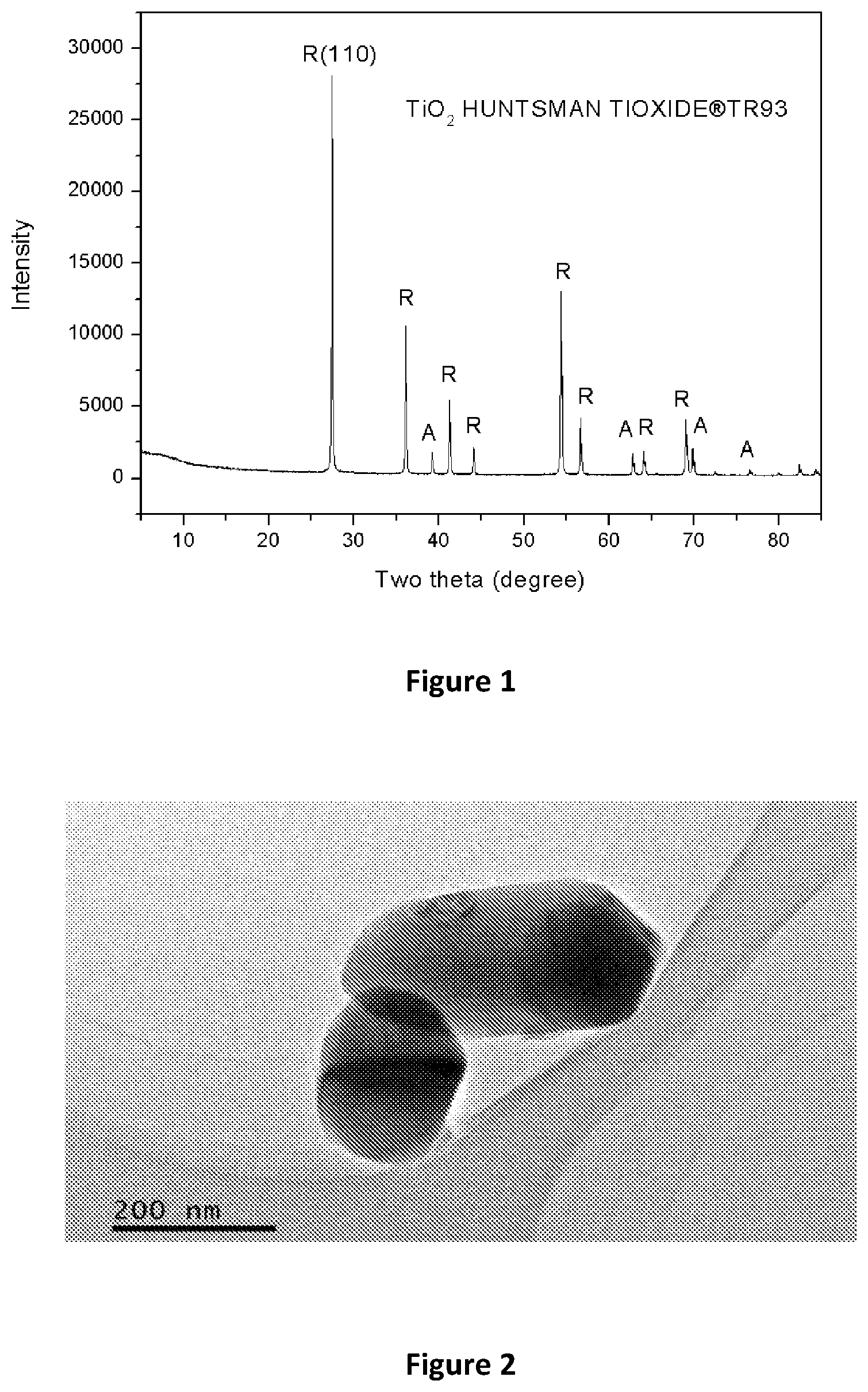
[0053] FIG. 1 is an XRD pattern of a pristine TiO.sub.2 powder;
[0054] FIG. 2 is a TEM image of pristine TiO.sub.2;
[0055] FIG. 3 is an XRD Pattern of a Na.sub.2Ti.sub.3O.sub.7 prepared at 120.degree. C.;
[0056] FIG. 4 is an XRD Pattern of an Na.sub.2Ti.sub.3O.sub.7 prepared at 150.degree. C.;
[0057] FIG. 5 is a an XRD Pattern of Na.sub.2Ti.sub.3O.sub.7 prepared at 180.degree. C.;
[0058] FIG. 6 is a TEM image of Na.sub.2Ti.sub.3O.sub.7 Prepared at 120.degree. C.;
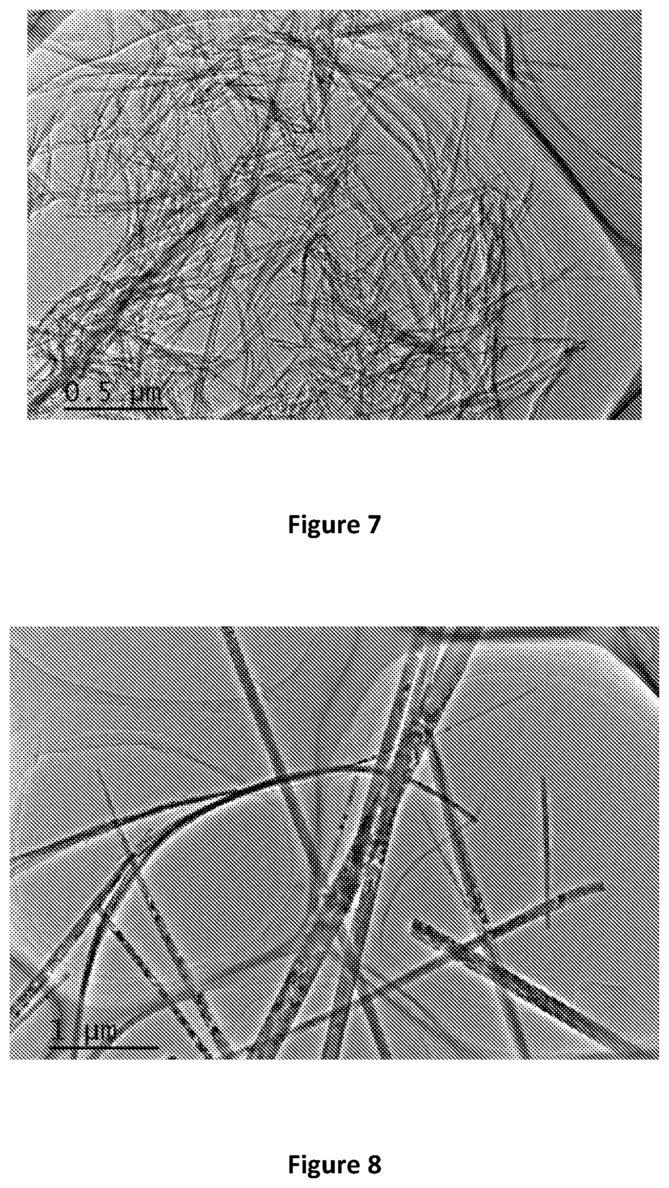
[0059] FIG. 7 is a TEM image of Na.sub.2Ti.sub.3O.sub.7 Prepared at 150.degree. C.;
[0060] FIG. 8 is a TEM image of Na.sub.2Ti.sub.3O.sub.7 Prepared at 180.degree. C.;
[0061] FIG. 9 is the XRD patterns of Li.sub.2TiO.sub.3 and H.sub.2TiO.sub.3 as per Example 3;
[0062] FIG. 10 is a TEM image of Li.sub.2TiO.sub.3;
[0063] FIG. 11 is a TEM image of H.sub.2TiO.sub.3;
[0064] FIG. 12 is an XRD pattern of Na.sub.2Ti.sub.3O.sub.7 (Synthesised at 120.degree. C.) after Adsorption Test;
[0065] FIG. 13 is an XRD pattern of Na.sub.2Ti.sub.3O.sub.7 (Synthesised at 120.degree. C.) after Adsorption Test;
[0066] FIG. 14 is a TEM image of Na.sub.2Ti.sub.3O.sub.7 (Synthesised at 120.degree. C.) after Adsorption Test;
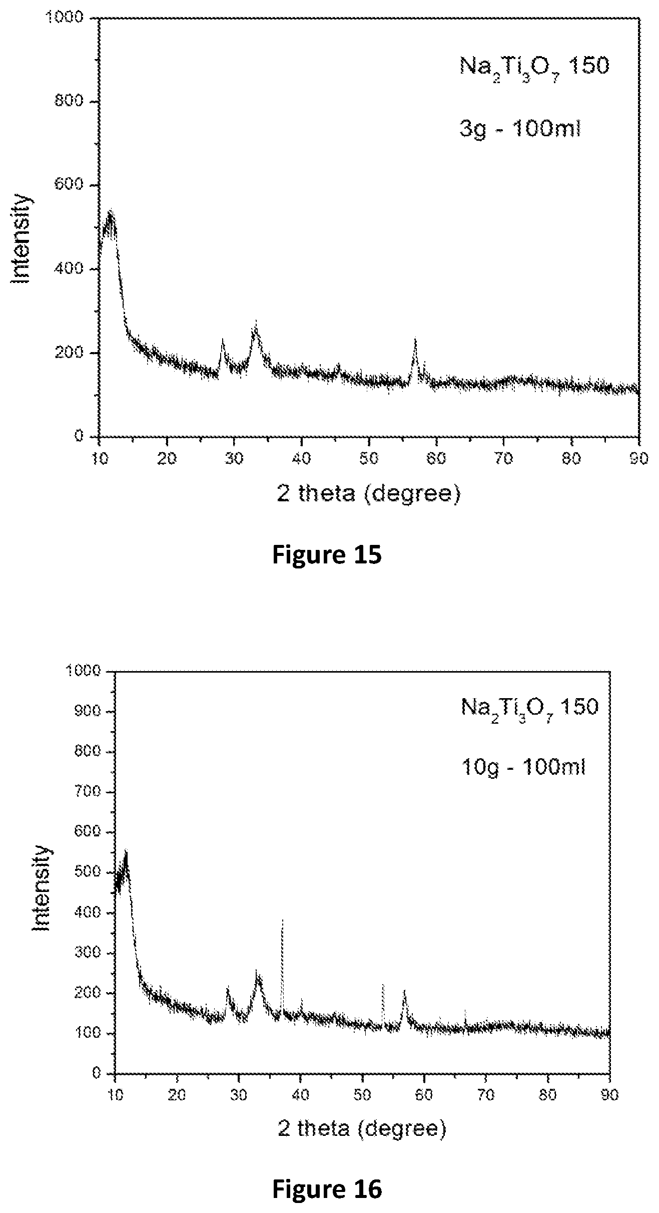
[0067] FIG. 15 is an XRD pattern of Na.sub.2Ti.sub.3O.sub.7 (Synthesised at 150.degree. C.) after Adsorption Test;
[0068] FIG. 16 is an XRD pattern of Na.sub.2Ti.sub.3O.sub.7 (Synthesised at 150.degree. C.) after Adsorption Test;
[0069] FIG. 17 is TEM image of Na.sub.2Ti.sub.3O.sub.7 (Synthesised at 150.degree. C.) after Adsorption Test;
[0070] FIG. 18 is an XRD pattern of Na.sub.2Ti.sub.3O.sub.7 (Synthesised at 180.degree. C.) after Adsorption Test;
[0071] FIG. 19 is an XRD pattern of Na.sub.2Ti.sub.3O.sub.7 (Synthesised at 180.degree. C.) after Adsorption Test;
[0072] FIG. 20 is TEM image of Na.sub.2Ti.sub.3O.sub.7 (Synthesised at 180.degree. C.) after Adsorption Test;
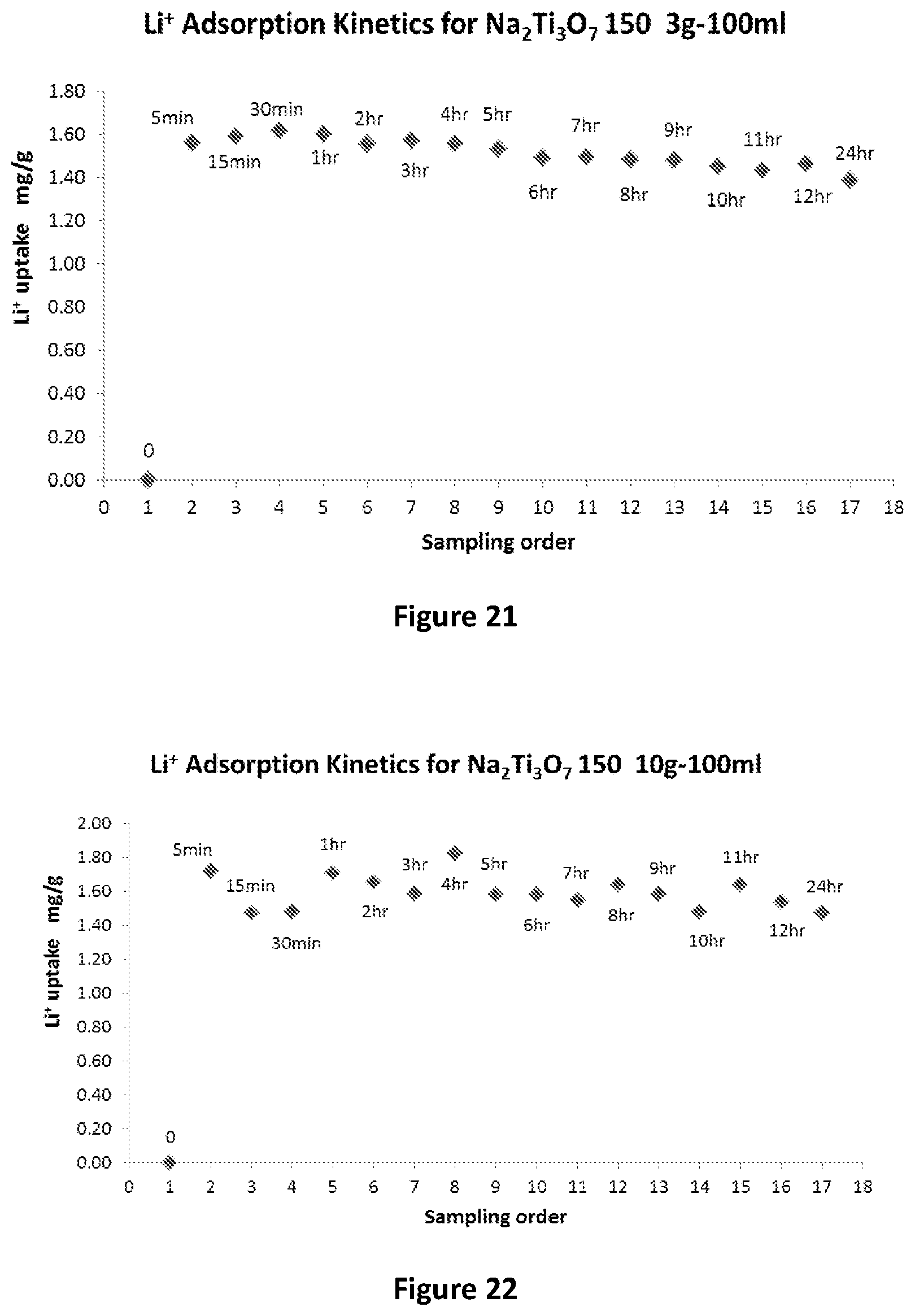
[0073] FIG. 21 is a kinetic adsorption test of sodium titanate Na.sub.2Ti.sub.3O.sub.7 sorbent synthesizes at 150.degree. C. in 100 ml brine solution (.about.300 ppm Li);
[0074] FIG. 22 is a kinetic adsorption test of sodium titanate Na.sub.2Ti.sub.3O.sub.7 sorbent synthesizes at 150.degree. C. in 100 ml brine solution (.about.300 ppm Li);
[0075] FIGS. 23(a) to 23(d) are the XRD characterisations for sodium titanate (Na.sub.2Ti.sub.3O.sub.7) synthesised at 150.degree. C. sorbents, observed at 4 sampling times;
[0076] FIG. 24 shows BET surface areas of sodium titanate synthesizes at 120.degree. C., 150.degree. C. and 180.degree. C. observed before and after adsorption;
[0077] FIG. 25 shows the kinetics of 3g sodium titanate sorbent prepared at 150.degree. C. (Na.sub.2Ti.sub.3O.sub.7 150) for 100 mL brine solution with different concentrations of Li.sup.+ ions and at different times of adsorption;
[0078] FIG. 26 shows the kinetics of 10 g sodium titanate sorbent prepared at 150.degree. C. (Na.sub.2Ti.sub.3O.sub.7 150) for 100 mL brine solution with different concentrations of Li.sup.+ ions and at different times of adsorption;
[0079] FIG. 27 shows an increased in amount of sorbent to 100 g/100 mL of brine solution (sorbent prepared at 150.degree. C.--Na.sub.2Ti.sub.3O.sub.7 150) for different concentrations f Li.sup.+ ions and at different times of adsorption;
[0080] FIG. 28 shows the results of the kinetic adsorption tests of hydrogen titanate sorbent (H.sub.2TiO.sub.3) in sorbent to solution ratio: 3 g-100 mL brine solution (.about.300 ppm Li);
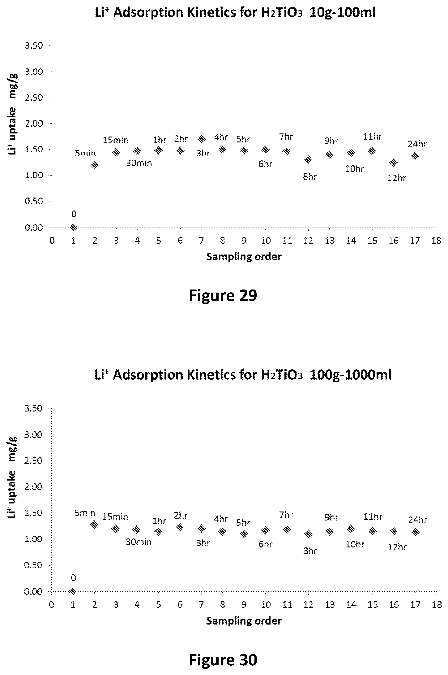
[0081] FIG. 29 shows the results of the kinetic adsorption tests of hydrogen titanate sorbent (H.sub.2TiO.sub.3) in sorbent to solution ratio: 10 g-100 mL brine solution (.about.300 ppm Li);
[0082] FIG. 30 shows the results of the kinetic adsorption tests of hydrogen titanate sorbent (H.sub.2TiO.sub.3) in sorbent to solution ratio: 100 g-1000 mL brine solution (.about.300 ppm Li);
[0083] FIG. 31 shows XRD data of the sorbent hydrogen titanate sorbent (H.sub.2TiO.sub.3) before and after adsorption at different times;
[0084] FIG. 32 shows BET surface area data of the sorbent hydrogen titanate sorbent (H.sub.2TiO.sub.3) before and after adsorption;
[0085] FIG. 33 shows the reaction kinetics of 3 g hydrogen titanate sorbent (H.sub.2TiO.sub.3), 100 mL brine solution with different concentrations of with different concentrations of Li.sup.+ ions;
[0086] FIG. 34 shows the reaction kinetics of 10 g hydrogen titanate sorbent (H.sub.2TiO.sub.3), 100 mL brine solution with different concentrations of with different concentrations of Li.sup.+ ions;
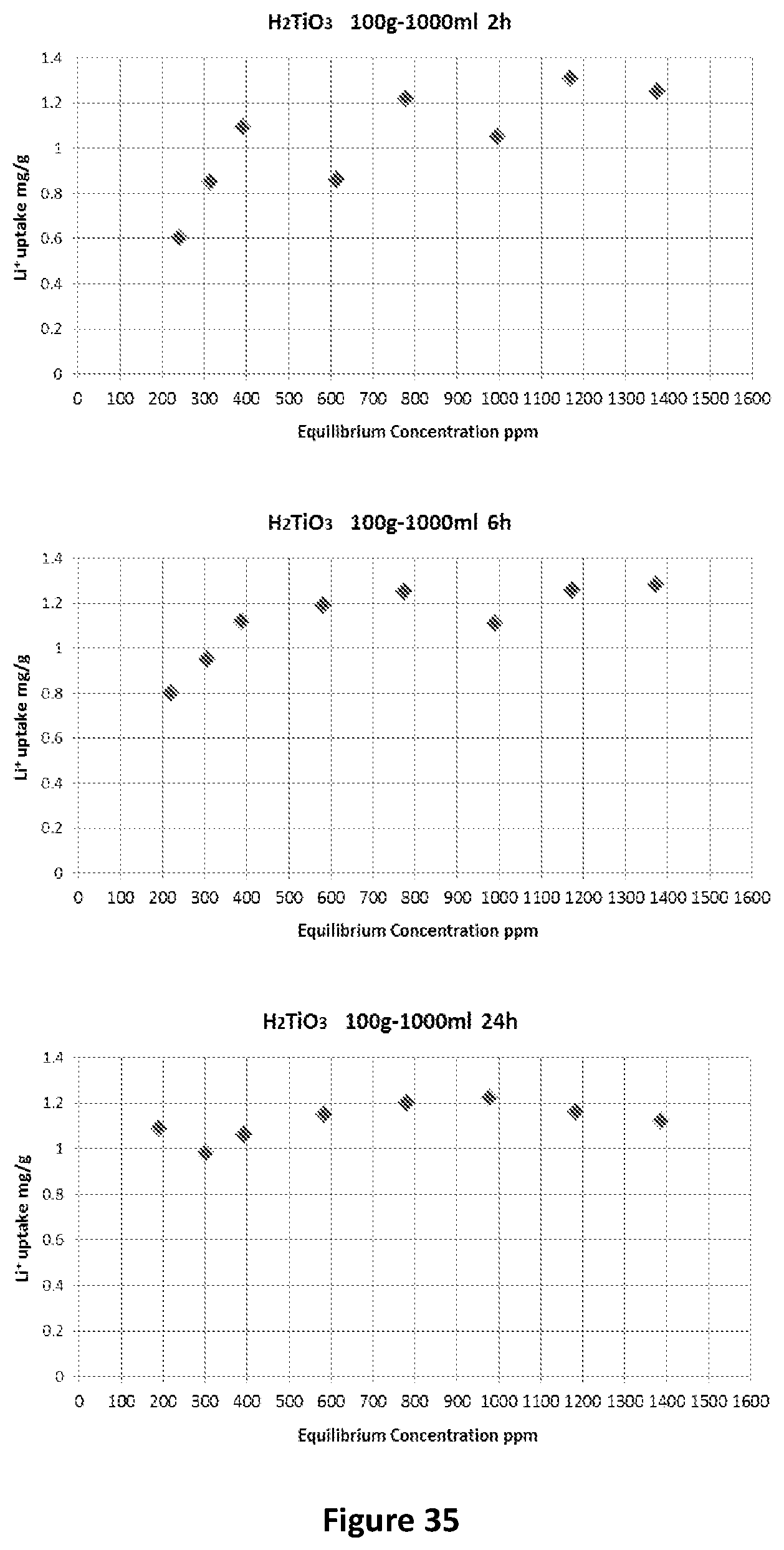
[0087] FIG. 35 shows the reaction kinetics of 100 g hydrogen titanate sorbent (H.sub.2TiO.sub.3), 1000 mL brine solution with different concentrations of with different concentrations of Li.sup.+ ions;
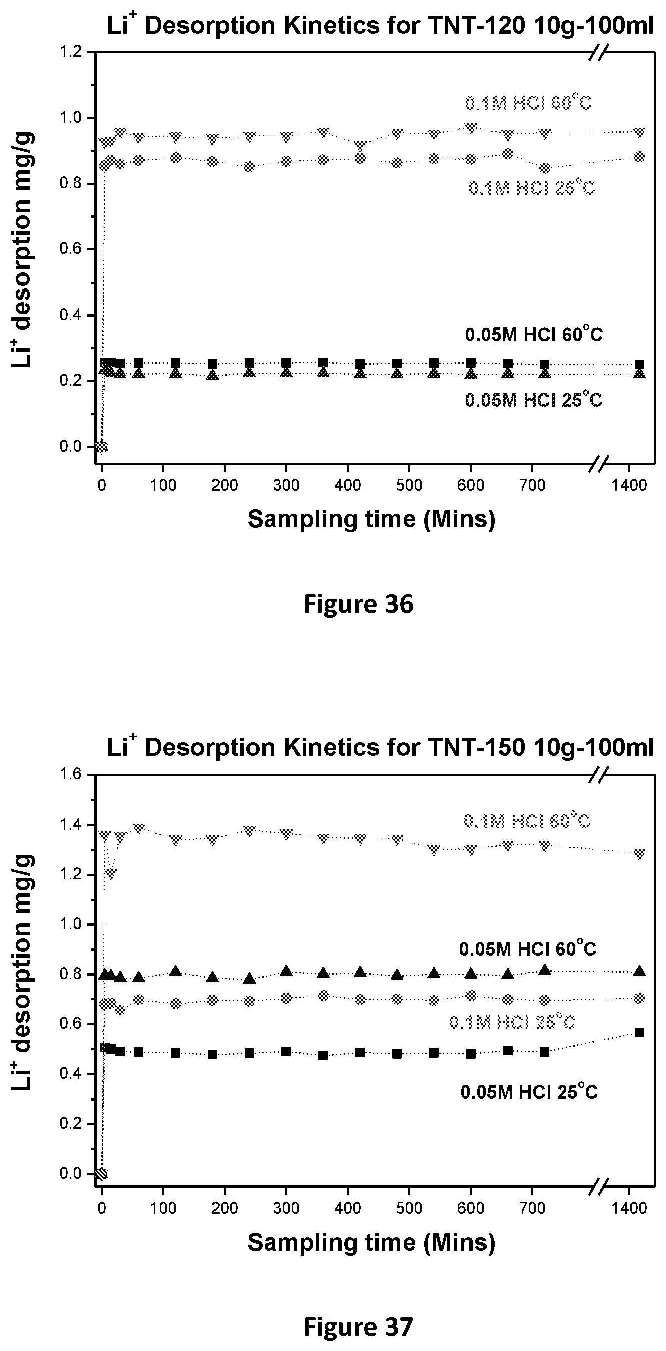
[0088] FIG. 36 shows the results of kinetic desorption testing for TNT-120;
[0089] FIG. 37 shows the results of kinetic desorption testing for TNT-150;
[0090] FIG. 38 shows the results of kinetic desorption testing for TNT-180;
[0091] FIG. 39 shows the desorption data for hydrogen titanate sorbent (H.sub.2TiO.sub.3);
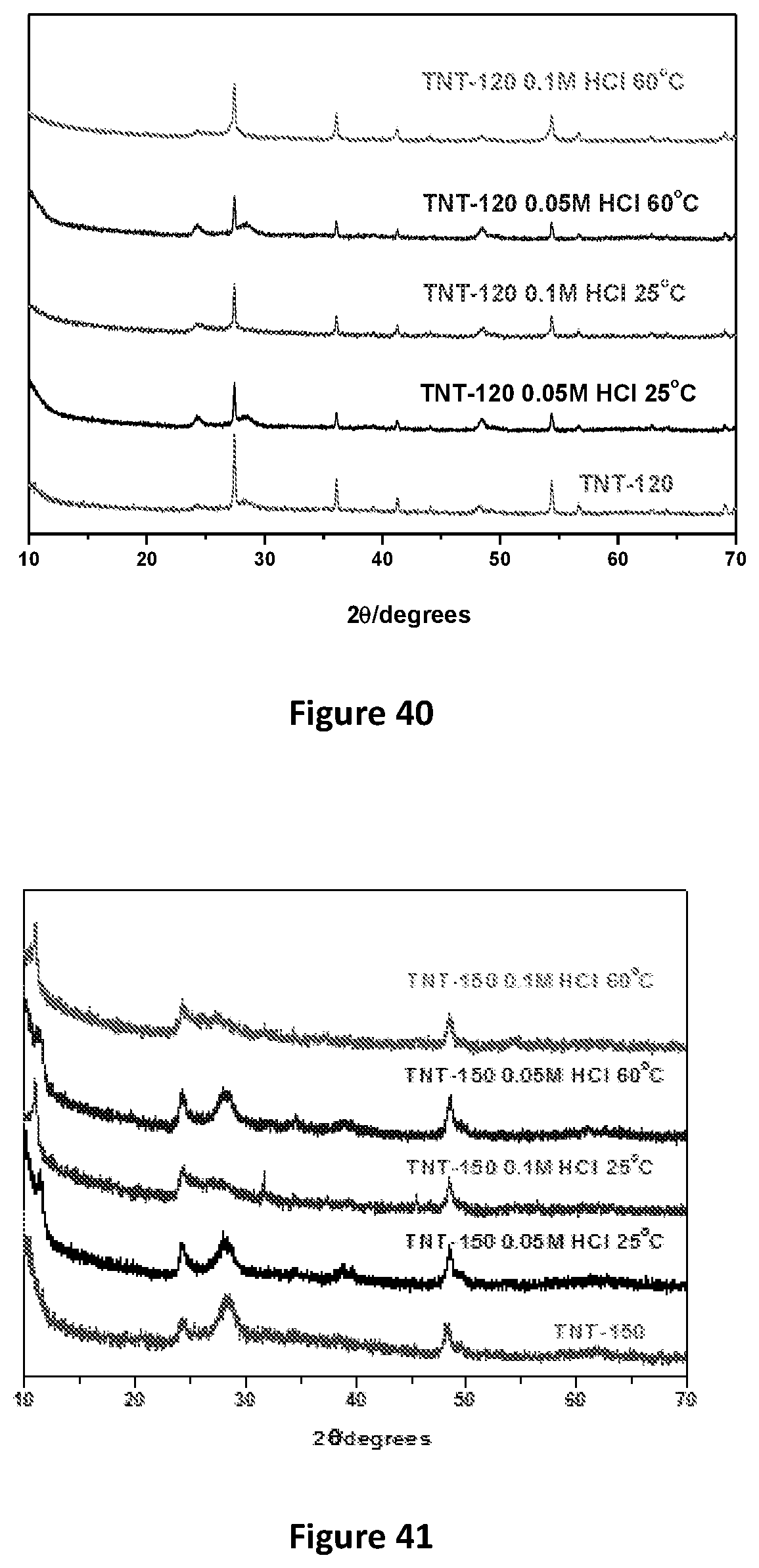
[0092] FIG. 40 shows XRD patterns of TNT-120 sorbent after adsorption in 300 ppm Li.sup.+ solution;
[0093] FIG. 41 shows XRD patterns of TNT-150 sorbent after adsorption in 300 ppm Li.sup.+ solution;
[0094] FIG. 42 shows XRD patterns of TNT-180 sorbent after adsorption in 300 ppm Li.sup.+ solution;
[0095] FIG. 43 shows XRD patterns of H.sub.2TiO.sub.3 sorbent after adsorption in 300 ppm Li.sup.+ solution;
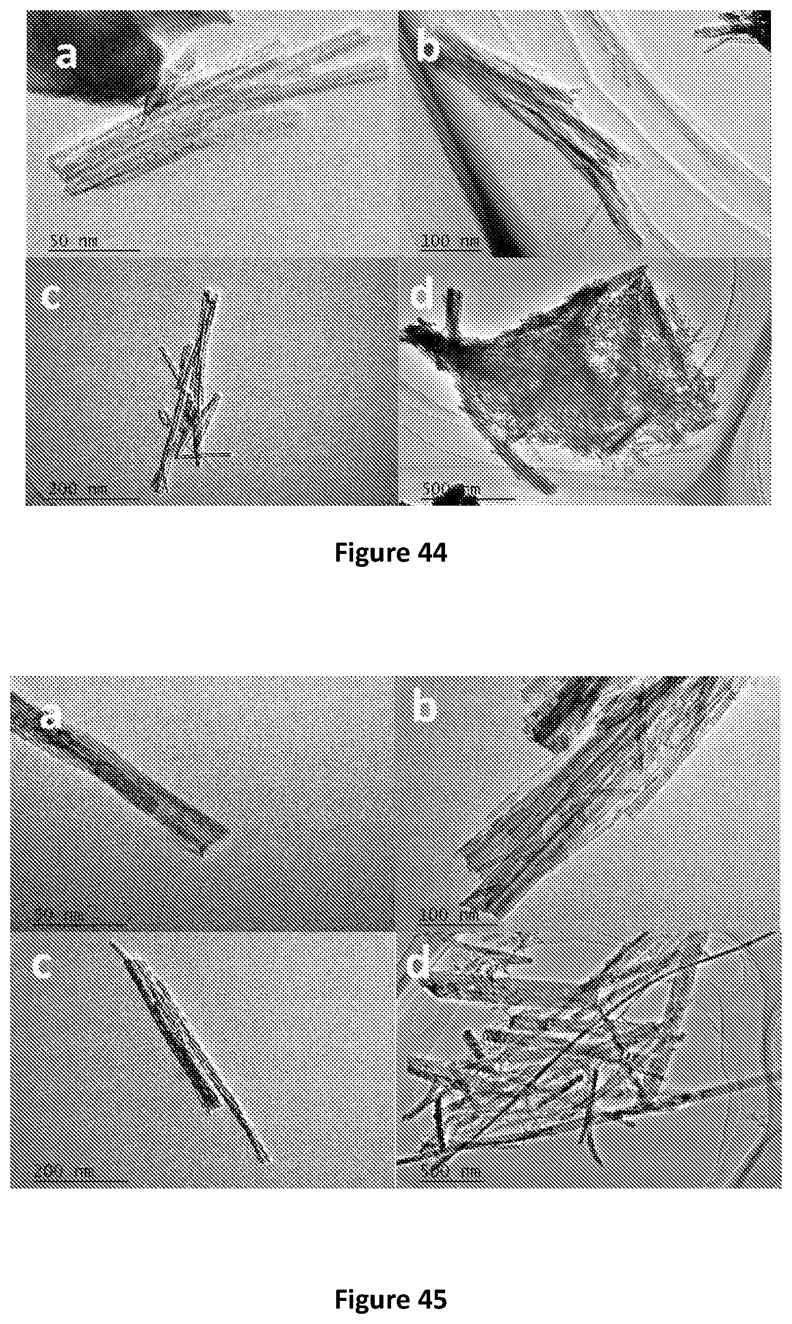
[0096] FIG. 44 shows TEM images of TNT-120 sorbents after desorption with 0.05M HCl at 25.degree. C.;
[0097] FIG. 45 shows TEM images of TNT-150 sorbents after desorption with 0.05M HCl at 25.degree. C.;
[0098] FIG. 46 shows TEM images of TNT-180 sorbents after desorption with 0.05M HCl at 25.degree. C.;
[0099] FIG. 47 shows TEM images of H.sub.2TiO.sub.3 sorbents after desorption with 0.05M HCl at 25.degree. C.;
[0100] FIG. 48 shows Na.sup.+ and Cl.sup.- ion permeation through a GO membrane;
[0101] FIG. 49 shows the filtration performance of modified GO membranes with different thickness (FIG. 49a) and different reduction time (FIG. 49b); and
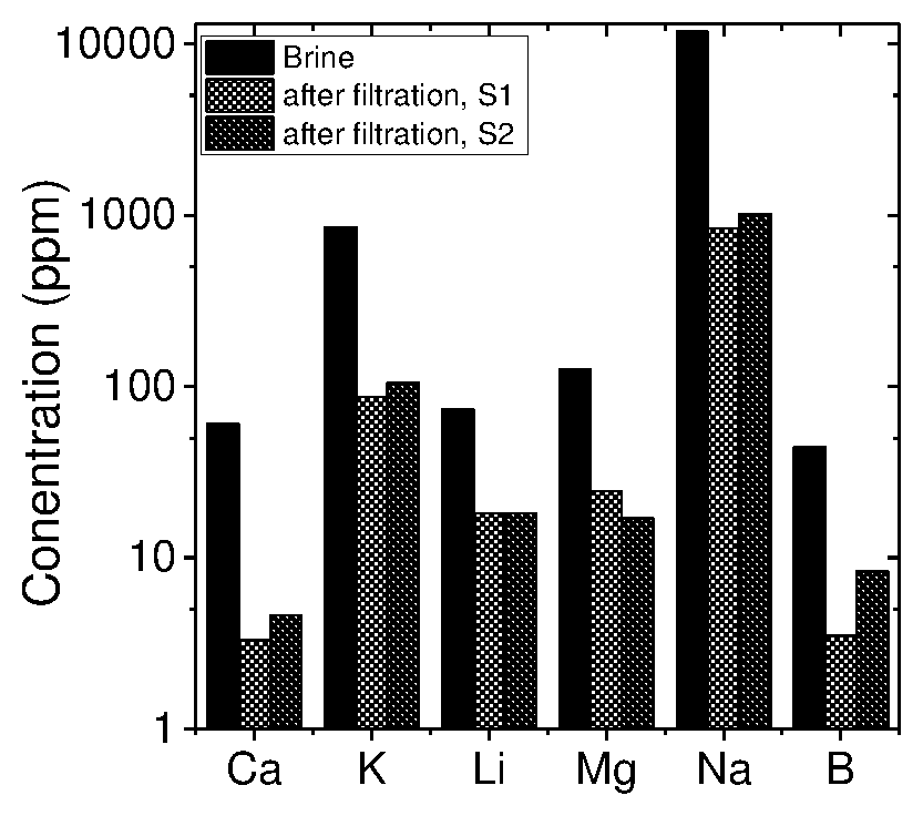
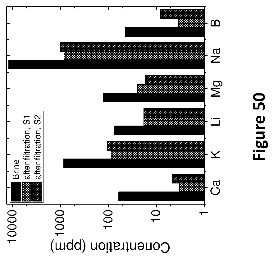
[0102] FIG. 50 shows the concentration of salts in a brine solution before and after filtration through a modified GO membrane, where the Y-axis--log scale and S1 and S2 represent data from two different membranes, the membrane used being 200 nm thick and 30 minute rGO.
BEST MODE(S) FOR CARRYING OUT THE INVENTION
[0103] The present invention provides a combined processing method for the purification of lithium containing solutions, the method comprising the method steps of passing a lithium containing solution to a first purification step in which the lithium containing solution is contacted with a titanate adsorbent whereby lithium ions are adsorbed thereon whilst rejecting substantially all other cations, the recovery of the adsorbed lithium providing a part-purified lithium containing solution, the part-purified lithium containing solution produced in the first purification step is then passed in whole or part to a second purification step in which a graphene based filter medium is utilised to provide a further purified lithium containing solution.
[0104] In one form, the lithium containing solution is a lithium containing brine. The brine to be treated initially contains impurities from the group of sodium, potassium, magnesium, calcium and borate. In one form of the present invention the brine contains lithium in the range of about 500 to 1500 ppm, and impurities including magnesium in the range of about 0.15% to 0.30%, calcium in the range of about 0.05% to 0.1%, sodium in the range of about 8 to 10%, potassium in the range of about 0.7% to 1.0%, and borate in the range of about 0.15% to 0.20%. In a more preferred form of the present invention, the brine contains about 700 ppm lithium, about 0.19% magnesium, about 0.09% calcium, about 8.8% sodium, about 0.8% potassium and about 0.18% borate.
[0105] The adsorbent is provided in the form of either a hydrated titanium dioxide or a sodium titanate. In one form of the present invention the hydrated titanium dioxide is produced from titanium dioxide.
[0106] The process in turn produces a substantially pure lithium chloride solution. The impurity concentration of the substantially pure lithium chloride solution does not exceed about 20 ppm.
[0107] The brine solution is preferably adjusted to a pH of 7 through the addition of a base. The base is preferably provided in the form of sodium hydroxide.
[0108] The contact between the brine solution and the adsorbent preferably takes place at or about room or ambient temperature. Room temperature is understood to be between about 20.degree. C. to 28.degree. C.
[0109] In one form of the present invention the brine is collected into a vessel and cooled to room temperature prior to its exposure to the adsorbent. The contact or residence time between the brine solution and the adsorbent is between about 4 to 24 hours.
[0110] The contact or residence time between the brine solution and the adsorbent is: [0111] a) between about 8 to 24 hours; [0112] b) between about 20 to 24 hours; or [0113] c) between about 8 to 16 hours.
[0114] It is to be understood that the contact time is to some extent dependent upon additional variables including reactor size and shape.
[0115] The recovery of lithium from the adsorbent is preferably achieved through the regeneration of the adsorbent by the addition of an acid solution and the adsorbed lithium is extracted to provide the part purified lithium containing solution. The acid solution is a solution of hydrochloric acid.
[0116] The amount of lithium extracted from the adsorbent through exposure to the acid solution is greater than about 90%. For example, the amount of lithium extracted from the adsorbent through exposure to the acid solution is about 100% of the adsorbed lithium.
[0117] The graphene based filter medium of the second purification step comprises a graphene membrane formed of one or more graphene, graphene oxide and/or reduced graphene oxide and to which the part-purified lithium containing solution is presented.
[0118] The passing of the part purified lithium containing solution to the second purification step produces a filtrate or permeate that is enriched in relative terms in lithium ions, providing the further purified lithium containing solution.
[0119] The second purification step is conducted under pressure. The pressure may be at or about 10 bar.
[0120] The further purified lithium containing solution is suitable is suitable for use in the production of battery grade lithium chemicals.
[0121] In one form, the graphene is provided as a graphene oxide membrane formed in turn from graphite oxide powder. The graphene oxide membrane may be supported on a first support that is in turn located in an aperture of a second support. The first support is, for example, an anodic alumina disc. The second support is, for example, a copper plate.
[0122] In one form the graphene is provided as a reduced graphene oxide membrane. The graphene oxide membrane may be reduced by way of exposure to ascorbic acid.
[0123] The area used for pressure filtration is about 1-2 cm.sup.2. The membranes may be further supported by a porous substrate. In one form the porous substrate may be provided in the form of polyether sulfone (PES).
[0124] An adhesive material may applied to the porous substrate to increase the bond between the substrate and the graphene material. The adhesive material is, for example, provided in the form of a polymer. The polymer is, in one form, a positively charged polymer, for example polydiallyldimethulammonium chloride.
[0125] The graphene membrane may have a thickness of between 30 to 200 nm. For example, the thickness of the graphene membrane is 150 to 200 nm.
[0126] The level of salt rejection achieved by the second purification step is 20% or greater as measured by the conductivity of the permeate relative to that of the part-purified lithium containing solution. Lithium is the least rejected ion or salt of the second purification step.
[0127] In one form, the first and second purification steps may comprise one or more stages, passes or repeats of contact or exposure between the lithium containing solution passed to them and to the adsorbent or filter medium, respectively.
[0128] The Applicants have found that the graphene based filter medium works most effectively if presented with a relatively dilute lithium containing solution, as opposed to being presented with what may be termed a `raw` brine. Such a raw brine is typically near saturated with sodium chloride. The part-purified lithium containing solution from the first purification step has been determined by the Applicants to be an appropriate if not ideal feed to the second purification step and is such that the graphene based filter medium may operate effectively to provide the further purified lithium containing solution of the present invention.
[0129] The present invention further provides a process for the synthesis of a titanate adsorbent. The titanate adsorbent is provided in the form of sodium titanate (Na.sub.2Ti.sub.3O.sub.7) and hydrogen titanate (H.sub.2TiO.sub.3).
[0130] The titanate adsorbent formed in accordance with this process is suitable for the extraction of lithium from a lithium containing solution. The lithium containing solution may be a brine. The brine may contain impurities from the group of sodium, potassium, magnesium, calcium and borate.
[0131] The combined processing method for the purification of lithium containing solutions of the present invention may be further understood with reference to the following non-limiting examples.
EXAMPLE 1
Synthesis of Na.sub.2Ti.sub.3O.sub.7 Nano-Tubes/Fibres
[0132] 150 g of TiO.sub.2 (Anatase type) powder was mixed with 3L NaOH solution (10 mol/L), and kept stirring for 2 hours, then transferred to 5L autoclave and react at each of 120.degree. C., 150.degree. C., and 180.degree. C. for 48 h. Resulting Na.sub.2Ti.sub.3O.sub.7 nano-tubes were washed using vacuum filtration until pH of filtrate was 7. The product weight after drying at 100.degree. C. was 175 g. This produced high purity Na.sub.2Ti.sub.3O.sub.7 nanotubes (over 95% product are tubes); the nanotubes have the largest specific surface area of 232 m.sup.2/g.
[0133] The sodium titanate was characterized by powder X-ray diffraction (XRD) and transmission electron microscopy (TEM) to confirm the morphological phase and structure.
[0134] In FIG. 1 there is shown the XRD pattern of the pristine TiO2 powder. This suggests that TiO2 material contained mainly rutile (R) TiO2 mixed with some anatase (A) phase.
[0135] In FIG. 2 there is shown a TEM image of pristine TiO.sub.2 is shown. It can be seen that the diameter of the TiO.sub.2 particles is around 100.about.200 nm.
Synthesis and XRD--Na.sub.2Ti.sub.3O.sub.7 (Sodium Titanate)
[0136] The XRD patterns of the Na-titanate exhibit apparent difference from the pristine TiO.sub.2 powder. The XRD patterns of these samples are in good agreement with that of monoclinic Na.sub.2Ti.sub.3O.sub.7 phase. The synthetic processes and XRD patterns of Na.sub.2Ti.sub.3O.sub.7 samples prepared at different temperatures 120.degree. C., 150.degree. C. and 180.degree. C. are provided below.
Synthesis of Na.sub.2Ti.sub.3O.sub.7 at 120.degree. C.
[0137] 150 g TiO.sub.2 powder was mixed with 3L NaOH solution (10 mol/L), and kept stirring for 2 h, then transferred to 5L autoclave and react at 120.degree. C. for 48 h. Resulting Na.sub.2Ti.sub.3O.sub.7 nanotubes were washed with water using vacuum filtration until pH value of filtrate was 7. Product weight after drying at 100.degree. C.: 175 g.
[0138] The XRD Pattern of Na.sub.2Ti.sub.3O.sub.7 Prepared at 120.degree. C. is shown in FIG. 3.
Synthesis of Na.sub.2Ti.sub.3O.sub.7 at 150.degree. C.
[0139] 150 g TiO.sub.2 powder mixed with 3 L NaOH solution (10 mol/L), and kept stirring for 2 h, then transferred to 5 L autoclave and react at 150.degree. C. for 48 h. Resulting Na.sub.2Ti.sub.3O.sub.7 nanotubes were washed with water using vacuum filtration until pH value of filtrate was 7. Product weight after drying: 171 g.
[0140] The XRD Pattern of Na.sub.2Ti.sub.3O.sub.7 Prepared at 1500 C is shown in FIG. 4.
Synthesis of Na.sub.2Ti.sub.3O.sub.7 at 180.degree. C.
[0141] 150 g TiO.sub.2 powder mixed with 3 L NaOH solution (10 mol/L), and kept stirring for 2 h, then transferred to 5 L autoclave and react at 180.degree. C. for 48 h. Resulting Na.sub.2Ti.sub.3O.sub.7 nanotubes were washed with water using vacuum filtration until pH value of filtrate was 7. Product weight after drying: 172 g.
[0142] The XRD Pattern of Na.sub.2Ti.sub.3O.sub.7 Prepared at 1800 C is shown in FIG. 5.
TEM: Na.sub.2Ti.sub.3O.sub.7
[0143] After the hydrothermal reaction, the TiO.sub.2 particle morphology is changed. As can be seen clearly from the TEM images of the hydrothermal reaction products, the long tubes are well crystallized of layered Na-titanate according to the TEM images of the samples. A TEM image of Na.sub.2Ti.sub.3O.sub.7 Prepared at 120.degree. C. is shown in FIG. 6. A TEM image of Na.sub.2Ti.sub.3O.sub.7 Prepared at 150.degree. C. is shown in FIG. 7. A TEM image of Na.sub.2Ti.sub.3O.sub.7 Prepared at 180.degree. C. is shown in FIG. 8.
Synthesis of H.sub.2TiO.sub.3 Nano-Tubes/Fibres
EXAMPLE 2
[0144] 150 g of TiO.sub.2 (Anatase type) and 13.9 g of Li.sub.2CO.sub.3 were mixed, ground and heated in an alumina crucible at a rate of ca 6.degree. C./min in air up to 700.degree. C. and maintained for the next 4 h. After cooling to room temperature, the solid powder (Li.sub.2TiO.sub.3) was treated with 0.2M HCl solution with occasional shaking for 24 h at room temperature (5 g solid in 1L HCl acid). The solid was separated by filtration, washed and deionized water until the filtrate was neutral, and allowed to dry at room temperature to obtain high purity H.sub.2TiO.sub.3.
EXAMPLE 3
[0145] Anatase type TiO.sub.2 (15.0 g, Ti 0.187 mole) and Li.sub.2CO.sub.3 (13.9 g, Li 0.376 mole) were mixed, ground and heated in an alumina crucible at a rate of ca. 6.degree. C./min in air up to 700.degree. C. and maintained for the next 4 h. After cooling to room temperature, the solid powder (Li2TiO.sub.3) was treated with 0.2 M HCl solution with occasional shaking for 24 h at room temperature (5 g of solid in 1L acid). The solid was separated by filtration, washed with deionized water until the filtrate was neutral and allowed to dry at room temperature to obtain the H.sub.2TiO.sub.3.
[0146] The precursor (Li.sub.2TiO.sub.3) and (H.sub.2TiO.sub.3) sorbent was prepared through solid calcination method. XRD patterns of precursor and H.sub.2TiO.sub.3 sorbent matches the known literature.
[0147] TEM analysis indicates that H.sub.2TiO.sub.3 sorbent is mostly round shape nanoparticles and nano-rods with average size 200-400 nm. Li.sub.2TiO.sub.3 precursor exhibits similar structure as H.sub.2TiO.sub.3 sorbent suggesting that acid treatment has negligible impact on the morphology of the sorbent.
[0148] The surface area of synthesized H.sub.2TiO.sub.3 sorbent at 20.0 m.sup.2/g is far less than Na.sub.2Ti.sub.3O.sub.7 nanotubes synthesized at 150.degree. C. (232 m.sup.2/g). The Brunauer-Emmett-Teller (BET) result is consistent with TEM analysis.
[0149] The XRD Patterns of Li.sub.2TiO.sub.3 and H.sub.2TiO.sub.3 are shown in FIG. 9. [0150] TEM: Li.sub.2TiO.sub.3
[0151] A TEM image of Li.sub.2TiO.sub.3 is shown at FIG. 10. [0152] TEM: H.sub.2TiO.sub.3
[0153] A TEM image of H.sub.2TiO.sub.3 is shown at FIG. 11.
EXAMPLE 4
Sorbent Tests
[0154] A brine solution, the composition of which is described in the table below (-j 300 ppm Li), was chosen for the adsorption tests.
TABLE-US-00001 TABLE 1 Composition of brine/L: Compound Mass (g) Na.sub.2SO.sub.4 23.53 Na.sub.2B.sub.4O.sub.7.cndot.10H.sub.2O 3.81 NaHCO.sub.3 0.32 NaCl 210.43 KCl 22.50 MgCl.sub.2.cndot.6H.sub.2O 40.80 CaCl.sub.2 1.25 LiCl 1.92
Sodium Titanate (Na.sub.2Ti.sub.3O.sub.7) Sorbent Behaviour
[0155] The kinetics of lithium adsorption by sodium titanate was determined by sampling the brine during adsorption at time intervals of 5 min, 15 min, 30 min, 1 hr, 2 hr, 3 hr, 4 hr, 5 hr, 6 hr, 7 hr, 8 hr, 9 hr, 10 hr, 11 hr, 12 hr, 24 hr (16 sampling times). The adsorption kinetics for all 9 sodium titanate sorbents was determined using brine solution of similar composition and no buffer. Analytical characterisation was done by ICP, XRD and BET methods on selected samples.
[0156] It was observed that the Li.sup.+ adsorption reached to its equilibrium in 5-15 minutes for most of the adsorption test.
[0157] XRD characterisation of the adsorbed sorbent confirmed that the structure remains unchanged, however weak characterization peaks of MgTiO.sub.x (x=3 or 5) were observed because of heavy presence of Mg in the brine and affinity of sorbent towards Mg.
[0158] It was also observed that after Li.sup.+ uptake, the specific surface area of Na.sub.2Ti.sub.3O.sub.7 decreases. Several observations and conclusions have also been made, including that Na.sub.2Ti.sub.3O.sub.7 synthesized at 150.degree. C. shows the highest Li.sup.+ uptake (1.42.+-.0.1 mg/g) compared to the Na.sub.2Ti.sub.3O.sub.7 synthesized at 120.degree. C. and 180.degree. C., when a Brine solution of 300 ppm Li.sup.+ concentration is used. Further, after Li.sup.+ uptake, very small nanoparticles (2-3 nm) were found on the surface of sodium titanate sorbents as indicated in TEM images. The XRD analysis show that those nanoparticles are mostly MgTiO.sub.x (x=3 or 5), this is thought to be due to the high concentration of Mg.sup.2+ (about 5000 ppm) in the brine solution.
XRD Pattern of Na.sub.2Ti.sub.3O.sub.7 (Synthesised at 120.degree. C.) After Adsorption Test
[0159] The Li brine (.about.300 ppm Li) 100 mL was adsorbed for 2 h in 3 g sorbent. The XRD pattern is shown in FIG. 12.
[0160] The Li brine (.about.300 ppm Li) 100 mL was adsorbed for 2 h in 10 g sorbent also. The XRD pattern is shown in FIG. 13.
[0161] The TEM images of Na.sub.2Ti.sub.3O.sub.7 (synthesised at 120.degree. C.) collected after adsorption test in 100 mL of brine (.about.300 ppm Li) for 2 h in 3 g sorbent are shown in FIG. 14.
XRD Pattern of Na.sub.2Ti.sub.3O.sub.7 (Synthesised at 150.degree. C.) After Adsorption Test
[0162] The Li brine (.about.300 ppm Li) 100 mL was adsorbed for 2 h in 3 g sorbent. The XRD pattern is shown in FIG. 15.
[0163] The Li brine (.about.300 ppm Li) 100 mL was adsorbed for 2 h in 10 g sorbent. The XRD pattern is shown in FIG. 16.
[0164] The TEM images of Na.sub.2Ti.sub.3O.sub.7 (synthesised at 150.degree. C.) collected after adsorption test in 100 mL of brine (.about.300 ppm Li) for 2 h in 3 g sorbent is provided in FIG. 17.
[0165] XRD Pattern of Na.sub.2Ti.sub.3O.sub.7 (Synthesised at 180.degree. C.) after Adsorption Test
[0166] The Li brine (.about.300 ppm Li) 100 mL was adsorbed for 2 h in 3 g sorbent. The XRD pattern is shown in FIG. 18.
[0167] The Li brine (.about.300 ppm Li) 100 mL was adsorbed for 2 h in 10 g sorbent. The XRD pattern is shown in FIG. 19.
[0168] The TEM images of Na.sub.2Ti.sub.3O.sub.7 (synthesised at 180.degree. C.) collected after adsorption test in 100 mL of brine (.about.300 ppm Li) for 2 h in 3 g sorbent are shown in FIG. 20.
[0169] ICP analysis results of sorption tests in for 3 g and 10 g sodium titanate sorbent in 100 ml brine solution (.about.300 ppm Li+) after 2h are provided in the below table.
TABLE-US-00002 TABLE 2 Brine (~300 ppm Li) Uptake (mg/g) Adsorbent Sorbent (g)-Solution (ml) Li Mg Na.sub.2Ti.sub.3O.sub.7 (120.degree. C.) 3 g-100 ml 0.68 4.43 10 g-100 ml 0.73 7.52 Na.sub.2Ti.sub.3O.sub.7 (150.degree. C.) 3 g-100 ml 1.42 .+-. 0.1 5.61 10 g-100 ml 1.30 .+-. 0.1 6.27 Na.sub.2Ti.sub.3O.sub.7 (180.degree. C.) 3 g-100 ml 0.41 1.2 10 g-100 ml 0.51 4.61
[0170] Na.sub.2Ti.sub.3O.sub.7 (150.degree. C.) shows the best results on Li uptake at 1.42 mg/g of sorbent in 100 mL brine solution adsorbed for 2 hours.
[0171] The Kinetic adsorption tests of sodium titanate Na.sub.2Ti.sub.3O.sub.7 sorbent synthesizes at 150.degree. C. in 100 ml brine solution (.about.300 ppm Li) are shown in FIGS. 21 and 22 confirming that the Li.sup.+ adsorption reaches to its equilibrium in 5-15 minutes for most of the adsorption tests.
[0172] The XRD characterisation for sodium titanate (Na.sub.2Ti.sub.3O.sub.7) synthesised at 150.degree. C. sorbents was observed at 4 of the sampling times, and shown in FIGS. 23(a) to (d). It was observed that the structure of sorbent remains unchanged.
[0173] BET surface areas of sodium titanate synthesizes at 120.degree. C., 150.degree. C. and 180.degree. C. were observed before and after adsorption and are shown in FIG. 24.
[0174] With the exception of sodium titanate synthesised at 120.degree. C. which nearly remains unchanged within the experimental error variation, all other sodium titanate samples showed decrease in BET surface area after adsorption.
[0175] Li equilibrium adsorption for sodium titanate sorbents for different concentration of Li in brine was also studied. It was found that Na.sub.2Ti.sub.3O.sub.7 sorbent synthesized at 150.degree. C. reaches the Li.sup.+ uptake equilibrium of 4.65 mg/g at Li.sup.+ concentration above 1,300 ppm when dispersed 3 g sorbent into 100 ml brine solution. An increase in the sorbent amount to 10 g, the uptake equilibrium was found to decrease to 2.5 mg/g.
[0176] Na.sub.2Ti.sub.3O.sub.7 120 and Na.sub.2Ti.sub.3O.sub.7 180 show much lower Li.sup.+ uptake equilibrium below 1.5 mg/g at those concentrations of Li in brine.
[0177] The kinetics of 3g sodium titanate sorbent prepared at 150.degree. C. (Na.sub.2Ti.sub.3O.sub.7 150) for 100 mL brine solution with different concentrations of Li.sup.+ ions and at different times of adsorption is shown in FIG. 25. The maximum adsorption at 4.65 mg/g of sorbent may be achieved in 2 hours at 1,300 ppm Li concentration in brine.
[0178] The kinetics of 10 g sodium titanate sorbent prepared at 150.degree. C. (Na.sub.2Ti.sub.3O.sub.7 150) for 100 mL brine solution with different concentrations of Li.sup.+ ions and at different times of adsorption is shown in FIG. 26. The adsorption of Li at .about.4 mg/g of sorbent is lower than using 3 g of sorbent/100 mL of brine solution.
[0179] An increased in amount of sorbent to 100 g/100 mL of brine solution (sorbent prepared at 150.degree. C.--Na.sub.2Ti.sub.3O.sub.7 150) for different concentrations of Li.sup.+ ions and at different times of adsorption is shown in FIG. 27. The adsorption of Li decreases significantly.
Sorbent Behaviour of Hydrogen Titanate (H.sub.2TiO.sub.3)
[0180] Li adsorption kinetics for H.sub.2TiO.sub.3 sorbents was determined by sampling the brine during adsorption at time intervals of 5 min, 15 min, 30 min, 1 hr, 2 hr, 3 hr, 4 hr, 5 hr, 6 hr, 7 hr, 8 hr, 9 hr, 10 hr, 11 hr, 12 hr, 24 hr (16 sampling times). The adsorption kinetics for H.sub.2TiO.sub.3 sorbents was determined using just 300 ppm Li brine solution.
[0181] For analytical characterisation, ICP was performed for all samples. XRD characterisation was performed for half of the H.sub.2TiO.sub.3 sorbent at 4 of the sampling times. BET characterisation was performed for the H.sub.2TiO.sub.3 sorbent synthesised before and after Li.sup.+ adsorption.
[0182] It was observed that the Li.sup.+ adsorption reached to its equilibrium after 30 minutes for H.sub.2TiO.sub.3 sorbent, which was found to be slower than Na.sub.2Ti.sub.3O.sub.7 nanotubes synthesized at 150.degree. C.
[0183] XRD patterns of H.sub.2TiO.sub.3 after Li.sup.+ adsorption suggests that the impact of adsorption process on H.sub.2TiO.sub.3 sorbent is negligible.
[0184] After Li.sup.+ uptake, the specific surface area of H.sub.2TiO.sub.3 sorbent was found to be decreased from 20 m.sup.2/g to 18.1 m.sup.2/g.
[0185] The FIGS. 28 to 30 show the results of the kinetic adsorption tests of hydrogen titanate sorbent (H.sub.2TiO.sub.3) in different sorbent to solution ratio: 3g-100mL, 10g-100mL, and 100g-1000mL brine solution (.about.300 ppm Li), respectively.
[0186] FIG. 31 shows XRD data of the sorbent hydrogen titanate sorbent (H.sub.2TiO.sub.3) before and after adsorption at different times.
[0187] FIG. 32 shows BET surface area data of the sorbent hydrogen titanate sorbent (H.sub.2TiO.sub.3) before and after adsorption.
[0188] The Li equilibrium adsorption for a hydrogen titanate sorbent was observed for different brine concentrations. ICP characterisation was performed for all the samples.
[0189] It was observed that H.sub.2TiO.sub.3 sorbent reaches the Li.sup.+ uptake equilibrium of 4.4 mg/g at Li.sup.+ concentration of 500 ppm when dispersed 3 g sorbent into 100 ml brine solution. Neither increasing nor decreasing Li.sup.+ concentration leads to reduced Li.sup.+ uptake capacity. Increase the sorbent amount to 10 g, the uptake equilibrium is decreased to 2.8 mg/g. The results suggest H.sub.2TiO.sub.3 sorbent exhibits better Li.sup.+ uptake at relatively low Li.sup.+ concentration (300-700 ppm) while Na.sub.2Ti.sub.3O.sub.7-150 sorbent exhibits better performance at high Li.sup.+ concentration (900-1500 pm). When using large scale of sorbent 100 g H.sub.2TiO.sub.3 to large scale of brine solution (1000 ml), the sorption capacity is rather low up to 1.3 mg/g only.
[0190] FIG. 33 shows the reaction kinetics of 3 g hydrogen titanate sorbent (H.sub.2TiO.sub.3), 100 mL brine solution with different concentrations of with different concentrations of Li.sup.+ ions.
[0191] FIG. 34 shows the reaction kinetics of 10 g hydrogen titanate sorbent (H.sub.2TiO.sub.3), 100 mL brine solution with different concentrations of with different concentrations of Li.sup.+ ions.
[0192] FIG. 35 shows the reaction kinetics of 100 g hydrogen titanate sorbent (H.sub.2TiO.sub.3), 1000 mL brine solution with different concentrations of with different concentrations of Li.sup.+ ions.
EXAMPLE 5
Recovery of Li/Regeneration of Sorbents
[0193] Recovery of Li/Regeneration of sorbents for different regeneration conditions (limited sorbent/brine combinations) was studied. The combination of the 4 titanate sorbents and 3 brine solutions were selected for assessment of Li recovery and sorbent regeneration. The hydrogen titanate sorbent with the same 2 brine solutions was also tested. All samples were tested under 0.05 M and 0.1 M HCl solution at 25.degree. C. and 60.degree. C. respectively. Regeneration kinetics were determined by sampling the solution at time intervals of 5 min, 15 min, 30 min, 1 h, 2 h, 3 h, 4 h, 5 h, 6 h, 7 h, 8 h, 9 h, 10 h, 11 h, 12 h, and 24 h.
[0194] Analytical characterisation was performed using ICP (inductively coupled plasma atomic emission spectroscopy), XRD (x-ray diffraction) and TEM (transmission electron microscopy).
[0195] The observations were that the Li.sup.+ recovery amount from sodium titanate synthesized at 150.degree. C. sorbent was the highest at 1.4 mg/g during all samples used for this recovery test, which are below 1.0 mg/g. ICP data of Li.sup.+ recovery kinetic data indicates that, when using brine solution with the composition as above, the Li.sup.+ desorption reached equilibration at 5 mins for sodium titanate synthesized at 150.degree. C. and 30 mins for H.sub.2TiO.sub.3 sorbent, respectively. The 0.1 M HCl solution exhibited superior desorption property compared with the diluted HCl solution (0.05 M) only except with H.sub.2TiO.sub.3 sorbent. The high desorption temperature (60.degree. C.) can increase the Li+desorption equilibration compared with that of room temperature.
[0196] According to the XRD characterization, 0.05 M HCl has negligible impact on the crystal structure of titanate nanotube sorbents. However, the XRD patterns suggests that concentrated HCl solution (0.1 M) can convert the sodium titanate to hydrogen titanate and anatase TiO.sub.2 phase. TEM images of 4 sorbents after desorption at 25.degree. C. using 0.05 M HCl suggested the unchanged morphology of 4 sorbents.
[0197] EXAMPLE 6
Kinetic Desorption Tests
[0198] Sodium Titanate Synthesized at 120.degree. C. (TNT 120)
[0199] 10 g of the adsorbed sorbent was dispersed in 100 ml recovery solutions of 0.05M HCl and 0.1M HCl, respectively. Two different desorption temperatures were applied to find the influence of temperature. The four groups of desorption data are plotted together for a clear comparison.
[0200] As shown in FIG. 36, the higher concentration of HCl recovery solution exhibited the higher recovery amount of Li.sup.+ from the used sodium titanate synthesized at 120.degree. C. (TNT 120). The elevated desorption temperature (60.degree. C.) is able to increase the Li.sup.+ recovery, but not significantly. The triangles are desorption data over time using 0.05 M HCl solution at 25.degree. C. The squares are desorption data over time using 0.05 M HCl solution at 60.degree. C. The diamonds are desorption data over time using 0.1 M HCl solution at 25.degree. C. The inverted triangles are desorption data over time using 0.1 M HCl solution at 60.degree. C.
[0201] Element desorption from TNT-120 sorbent after adsorption with 10 g sorbent after 24 h is provided in the table below.
TABLE-US-00003 TABLE 3 Desorption Desorption Element release (mg/L) Adsorbent agent temperature Li B Ca K Mg Na TNT-120 0.05M 25.degree. C. 0.25 0.14 0.03 0.56 0.02 11.7 HCl TNT-120 0.1M HCl 25.degree. C. 0.88 0.17 5.49 5.73 2.43 39.7 TNT-120 0.05M 60.degree. C. 0.56 0.42 0.03 2.81 0.30 54.91 HCl TNT-120 0.1M HCl 60.degree. C. 0.95 0.18 5.8 5.67 1.9 41.5
[0202] Sodium Titanate Synthesized at 150.degree. C. (TNT 150)
[0203] 10 g of the sorbent TNT 150 was dispersed in 100 ml recovery solutions of 0.05M HCl and 0.1 M HCl respectively. Two different desorption temperatures were applied. The four groups of desorption data are plotted together for a clear comparison.
[0204] The Li.sup.+ recovery amount from TNT-150 sorbent is the highest (1.4 mg/g) during all samples used for this recovery test.
[0205] At a same temperature, the higher concentration of HCl recovery solution exhibited the higher recovery amount of Li.sup.+ from the used TNT-150 sorbents, as shown in FIG. 37. The elevated desorption temperature (60.degree. C.) is able to increase the Li.sup.+ recovery significantly, this is quite different from the other recovered samples. The triangles are desorption data over time using 0.05 M HCl solution at 25.degree. C. The squares are desorption data over time using 0.05 M HCl solution at 60.degree. C. The diamonds are desorption data over time using 0.1 M HCl solution at 25.degree. C. The inverted triangles are desorption data over time using 0.1 M HCl solution at 60.degree. C.
[0206] The following table depicts the element desorption from TNT-150 sorbent after adsorption brine solution with 10 g sorbent after 24 h.
TABLE-US-00004 TABLE 4 Desorption Desorption Element release (mg/L) Adsorbent agent temperature Li B Ca K Mg Na TNT-150 0.05M 25.degree. C. 0.488 0.37 0.03 2.6 0.22 48.59 HCl TNT-150 0.1M HCl 25.degree. C. 0.7035 0.39 6.07 6.38 1.09 71.96 TNT-150 0.05M 60.degree. C. 0.81 0.38 0.26 7.04 0.86 75.87 HCl TNT-150 0.1M HCl 60.degree. C. 1.29 0.38 0.27 3.01 1.01 75.76
[0207] Sodium Titanate Synthesized at 180.degree. C. (TNT 180)
[0208] The collected sodium titanate sorbent TNT-180 after adsorption in brine solution, 10g dispersed in 100 ml recovery solutions of 0.05M HCl and 0.1M HCl, respectively. Two different desorption temperatures were applied. The four groups of desorption data are plotted together for a clear comparison and shown in FIG. 38.
[0209] The higher concentration of HCl recovery solution exhibited the higher recovery amount of Li.sup.+ from the used TNT-180 sorbents.
[0210] The elevated desorption temperature (60.degree. C.) did not show a clear increase of Li.sup.+ recovery. The triangles are desorption data over time using 0.05 M HCl solution at 25.degree. C. The squares are desorption data over time using 0.05 M HCl solution at 60.degree. C. The diamonds are desorption data over time using 0.1 M HCl solution at 25.degree. C. The inverted triangles are desorption data over time using 0.1 M HCl solution at 60.degree. C.
[0211] The following table depicts the element desorption from TNT-180 sorbent after adsorption in brine solution with 10 g sorbent after 24 h.
TABLE-US-00005 TABLE 5 Desorption Desorption Element release (mg/L) Adsorbent agent temperature Li B Ca K Mg Na TNT-180 0.05M 25.degree. C. 0.3347 0.11 0.01 1.05 0.03 29.60 HCl TNT-180 0.1M HCl 25.degree. C. 0.832 0.11 1.70 2.60 0.44 80.06 TNT-180 0.05M 60.degree. C. 0.4916 0.13 0.02 1.08 0.09 37.72 HCl TNT-180 0.1M HCl 60.degree. C. 1.041 0.15 1.66 3.03 0.38 94.96
[0212] Hydrogen Titanate
[0213] The collected hydrogen titanate sorbent (H.sub.2TiO.sub.3) after adsorption in brine solution, 10 g sorbent was dispersed in 100 ml recovery solutions of 0.05M HCl and 0.1 M HCl, respectively. Two different desorption temperatures were applied. The four groups of desorption data are plotted together for a clear comparison, as shown in FIG. 39.
[0214] The different concentration of recovery solution or different recovery temperatures do not show a significant impact on the Li.sup.+ recovery as it shown to other sodium titanate samples. FIG. 39 shows kinetic desorption test of H.sub.2TiO.sub.4 sorbent after adsorption in brine solution. The triangles are desorption data over time using 0.05 M HCl solution at 25.degree. C.; the squares are desorption data over time using 0.05 M HCl solution at 60.degree. C.; the diamonds are desorption data over time using 0.1 M HCl solution at 25.degree. C.; the inverted triangles are desorption data over time using 0.1 M HCl solution at 60.degree. C.
[0215] The following table shows element desorption from H.sub.2TiO.sub.4 sorbent after adsorption in brine solution with 10 g sorbent after 24 h.
TABLE-US-00006 TABLE 6 Desorption Desorption Element release (mg/L) Adsorbent agent temperature Li B Ca K Mg Na H.sub.2TiO.sub.3 0.05M 25.degree. C. 0.731 0.004 0.05 0.10 0.016 1.90 HCl H.sub.2TiO.sub.3 0.1M HCl 25.degree. C. 0.795 0.01 0.08 0.14 0..03 2.50 H.sub.2TiO.sub.3 0.05M 60.degree. C. 0.8085 0.006 0.07 0.20 0.03 2.28 HCl H.sub.2TiO.sub.3 0.1M HCl 60.degree. C. 0.7554 0.02 0.10 0.23 0.10 2.03
XRD Analysis
[0216] The XRD patterns suggested that concentrated HCl solution (0.1 M) can convert the sodium titanate TNT-120 and TNT-150 to hydrogen titanate and anatase TiO.sub.2 phase slightly. TNT-180 has a more significant phase transformation, probably not feasible for repeated use. The possible impact of this slight phase change of sorbent in HCl solution to the next cycle Li.sup.+ uptake and recovery may explored in the future study.
XRD of TNT-120 After Li Recovery
[0217] FIG. 40 shows XRD patterns of TNT-120 sorbent after adsorption in 300 ppm Li.sup.+ solution. From the bottom, the first line is original TNT-120. The second line is TNT-120 after desorption using 0.05 M HCl solution at 25.degree. C. The third line is TNT-120 after desorption using 0.1 M HCl solution at 25.degree. C. The fourth line is TNT-120 after desorption using 0.05 M HCl solution at 60.degree. C. The top line TNT-120 after desorption using 0.1 M HCl solution at 60.degree. C.
XRD of TNT-150 After Li Recovery
[0218] FIG. 41 shows the XRD patterns of TNT-150 sorbent after adsorption in 300 ppm Li.sup.+ solution. Reading from the bottom, the first line is original TNT-150. The second line is TNT-150 after desorption using 0.05 M HCl solution at 25.degree. C. The third line is TNT-150 after desorption using 0.1 M HCl solution at 25.degree. C. The fourth line is TNT-150 after desorption using 0.05 M HCl solution at 60.degree. C. The top line TNT-150 after desorption using 0.1 M HCl solution at 60.degree. C.
XRD of TNT-180 After Li Recovery
[0219] FIG. 42 shows the XRD patterns of TNT-180 sorbent after adsorption in 300 ppm Li.sup.+ solution. Reading from the bottom, the first line is the original TNT-180. The second line is TNT-180 after desorption using 0.05 M HCl solution at 25.degree. C. The third line is TNT-180 after desorption using 0.1 M HCl solution at 25.degree. C. The fourth line is TNT-180 after desorption using 0.05 M HCl solution at 60.degree. C. The top line is TNT-180 after desorption using 0.1 M HCl solution at 60.degree. C.
XRD of H.sub.2TiO.sub.3 After Li Recovery
[0220] FIG. 43 shows the XRD patterns of H.sub.2TiO.sub.3 sorbent after adsorption in 300 ppm Li.sup.+ solution. Reading from the bottom up, the first line is the original H.sub.2TiO.sub.3. The second line is H.sub.2TiO.sub.3 after desorption using 0.05 M HCl solution at 25.degree. C. The third line is H.sub.2TiO.sub.3 after desorption using 0.1 M HCl solution at 25.degree. C. The fourth line is H.sub.2TiO.sub.3 after desorption using 0.05 M HCl solution at 60.degree. C. The fifth line is H.sub.2TiO.sub.3 after desorption using 0.1 M HCl solution at 60.degree. C.
EXAMPLE 7
TEM Analysis
[0221] TEM images of Desorbed TNT-120
[0222] TEM images of TNT-120 sorbents after desorption with 0.05M HCl at 25.degree. C. are shown in FIG. 44. The comparison of sorbent morphology before and after desorption indicates that the Li.sup.+ recovery process does not show significant impact on the nanofiber. TEM images of TNT-120 sorbent after desorption with 0.05M HCl at 25.degree. C. under different resolution (a) 50 nm, (b) 100 nm, (c) 200 nm, (d) 500 nm are shown.
TEM Images of Desorbed TNT-150
[0223] EM images of TNT-150 sorbents after desorption with 0.05M HCl at 25.degree. C. are shown in FIG. 45. The comparison of sorbent morphology before and after desorption indicates that the Li.sup.+ recovery process does not show significant impact on the nanofiber. TEM images of TNT-150 sorbent after desorption with 0.05M HCl at 25.degree. C. under different resolution (a) 50 nm, (b) 100 nm, (c) 200 nm, (d) 500 nm are shown.
TEM Images of Desorbed TNT-180
[0224] The TEM images of TNT-180 sorbents after desorption with 0.05M HCl at 25.degree. C. are shown in FIG. 46. The TNT-180 nanotubes are relatively large than TNT-120 and TNT-150, therefore low resolution. The comparison of sorbent morphology before and after desorption indicates that the Li.sup.+ recovery process does not show significant impact on the nanofiber. TEM images of TNT-180 sorbent after desorption with 0.05M HCl at 25.degree. C. under different resolution (a) 50 nm, (b) 500 nm, (c) 1000 nm, (d) 2000 nm are shown.
TEM Images of H.sub.2TiO.sub.3
[0225] The TEM images of H.sub.2TiO.sub.3 sorbents after desorption with 0.05M HCl at 25.degree. C. are shown in FIG. 47. The H.sub.2TiO.sub.3 sorbents are still particle aggregations over 100 nm, therefore. TEM images above 200 nm are collected as shown in the following figure. The comparison of sorbent morphology before and after desorption indicates that the Li.sup.+ recovery process removed the hand-shape particles from original sorbent. It is inferred that the hand-shape particles are Li2CO.sub.3 that dissolved by HCl solution, the amorphous particles aggregations, on the other hand, are H.sub.2TiO.sub.3 nanoparticles and their morphology is not influenced by desorption processes. TEM images of TNT-180 sorbent after desorption with 0.05M HCl at 25.degree. C. under different resolution (a) and (b) 200 nm, (c) 500 nm, (d) 1000 nm is shown.
EXAMPLE 8
Brine Treatment With Adsorbents
[0226] Both sodium titanate (Na.sub.2Ti.sub.3O.sub.7) and hydrogen titanate (H.sub.2TiO.sub.3) are, as noted above, preferred forms of the adsorbents used in the process of the present invention. Suitable sodium titanate (Na.sub.2Ti.sub.3O.sub.7) and/or hydrogen titanate (H.sub.2TiO.sub.3) were synthesised as per methods described above. The function of the adsorbent material in the process of the present invention, without being limited by theory, is to absorb lithium ions from the LiCl brine and thereby rejecting the impurities, including competing cations.
[0227] The adsorbent (Na.sub.2Ti.sub.3O.sub.7 and/or H.sub.2TiO.sub.3) used in this embodiment of the present invention may advantageously be placed in a series of column. Further, the adsorbent may be placed in a series of columns and the brine solution may be directed through this series of columns. In other preferred embodiments the adsorbent columns may be placed before the brine solution.
[0228] The lithium containing brine with the composition stated above was placed in a beaker. The adsorbent (Na.sub.2Ti.sub.3O.sub.7 or H.sub.2TiO.sub.3) was packed in a series of vertical columns. The amount of adsorbent top pack in the series of columns to treat a particular brine was selected to adsorb maximum Li from the brine in provided series of columns as per data obtained from our R&D and stated above.
[0229] The brine was passed through the series of vertical columns and retained for 5 minutes to several hours for complete adsorption of lithium in the adsorbent packed columns. After this, the lithium adsorbed in the adsorbent was stripped from the adsorbent using a dilute HCl acid the optimum strength as discussed and provided above. The stripped solution was analysed for the concentration of Li and all other impurities such as B, Na, K, Ca and Mg. The lithium was found to be extracted at >90% from the brine.
[0230] The following table shows the comparative analyses of the original brine solution before feeding to the adsorbents and after desorbed from the adsorbents.
TABLE-US-00007 TABLE 7 Original Brine Desorbed Brine ppm Desorbed Brine Elements ppm Na.sub.2Ti.sub.3O.sub.7 (TNT 150) ppm H.sub.2TiO.sub.3 Li 316 294 290 B 432 87 2.3 Ca 410 62 26 K 12,000 686 72 Mg 5,000 230 2 Na 100,000 17,266 820
[0231] An appropriate apparatus to be used in carrying out the first purification step of the present invention may be any manifold system whereby a lithium containing brine can be delivered to a series of columns containing an adsorbent and then ultimately collected in a receiving vessel. The apparatus may also have a means for drawing aliquots of LiCl for analysis. Such means may be a sample port comprising a resilient septum affixed in line to the apparatus. The apparatus may be composed of several vessels such as glass flasks, ceramic containers, metal containers or other typical non-reactive chemical reaction vessels. The vessels may be connected using non-reactive polymeric tubing, metal pipe or tube, or glass pipe or tube. The apparatus may be sectioned off using any type of valve stopcock or clamp depending on the composition of the tubing or piping.
[0232] The combined processing method for the purification of lithium containing solutions of the present invention further provides a method for the purification of semi-pure or part-purified LiCl solution obtained as may be produced as described above from a brine by using an adsorbent. The combined processing method further comprises passing the semi-pure LiCl solution obtained after desorption of adsorbent to a graphene based filter medium, for example a graphene based membrane. The graphene based membrane is, in one form, prepared from graphene oxide (GO) or reduced graphene oxide (rGO), which allows appropriate permeation through the membrane.
EXAMPLE 9
Graphene Filter Medium Preparation--GO Membrane
[0233] Graphene oxide dispersion is prepared by the ultra-sonication of graphite oxide powder in water and subsequent centrifugation. The vacuum filtration of the as-prepared solution on a first support, for example an anodic alumina disc, provides with subsequent drying a free-standing graphene oxide (GO) membrane. The GO membrane is then glued onto a second support, for example a copper plate having a 2 cm aperture provided in the centre thereof, for the conduct of permeation experiments.
EXAMPLE 10
Permeation Experiments
[0234] The permeation experiment was carried out such that the GO membranes, supported by the copper plate, were clamped between two O-rings and then fixed between feed and permeate compartments to provide a leak tight environment. The part-purified LiCl solution obtained after desorption from the adsorbent was used as feed and deionized water in the permeate side. As a result of the concentration gradient across the membrane, ions tend to diffuse through the membrane and reach the permeate side. Permeate solution is collected after 24 h and chemical analysis is conducted to quantify the ions in the permeate side.
[0235] The percentage of rejection for Mg.sup.2+ ion is 94% whereas 45% for Li.sup.+, Na.sup.+ and K.sup.+ ions. In FIG. 48, it can be seen that Na.sup.+ and Cl.sup.- ion permeation through GO is faster than other ions. The Applicants understand this demonstrates the potential of GO membranes for the selective removal of salt from the concentrated brine solution.
[0236] The results are shown in the following table and in FIG. 48.
TABLE-US-00008 TABLE 8 Na K Mg SO4 (mg/L) (mg/L) (mg/L) Li (mg/L) Cl (mg/L) (mg/L) Feed 111,000 9,420 3,360 302 180,000 14,000 Feed (ICP data) 47630 5495 2614 224 102,870 9,778 Permeate (ICP 25,205 3,203 155 120 62,237 768 data) Ratio 1.89 1.71 16.86 1.87 1.65 12.73 (feed:Permeate)
Pressure Filtration Using GO Membrane
[0237] To investigate the feasibility of using GO membrane in separating aqueous LiCl species from control aqueous brine or selective removal certain ions in the brine pressure filtration experiments were performed using a Sterlitech HP4750.TM. stirred cell. For pressure filtration, porous Poly ether sulfone (PES) was used as a substrate to increase the mechanical integrity of the membrane. To obtaining a reasonable flux we optimised the GO membrane thickness to 200-500 nm. The typical area used for pressure filtration was 1-2 cm.sup.2. GO membrane on PES was then fixed inside the stirred cell using a rubber 0-ring to avoid any possible leakage in the experiment. Brine solution was used as a feed solution and collected the water on filtrate side by applying a pressure of 10 bar using a compressed nitrogen gas cylinder.
[0238] Salt concentration on the filtrate side was analysed by checking the conductivity of the water solution and found that total salt rejection is 20%.
Preparation of rGO Membranes
[0239] GO membranes on PES substrates were found to be disintegrating after long time exposure to brine solution at high pressure and to resolve this issue we have partially reduced GO membrane with ascorbic acid. Partial reduction of GO decreased the amount of functional groups present in the membrane and subsequently reduced the hydrophilicity and wettability of the membrane. The ascorbic acid reduced graphene oxide (rGO) is found to be more stable in brine solution after long exposure.
Permeation Through rGO Membrane
[0240] As per the GO membranes referred to above, rGO membranes deposited on PES substrate (.about.5 cm dia membrane) were evaluated with pressure filtration. Even though the membrane is more stable after partial reduction, under high pressure, rGO layer from the PES got peeled off and damaged during the filtration. This suggests that reduced functional groups on rGO may have decreased the adhesion between the rGO layer and PES substrate. It is understood that increasing the adhesion of the rGO layer to PES will be possible by surface modification of PES with a polyelectrolyte.
EXAMPLE 10
Graphene Filter Medium Preparation--rGO Membrane
[0241] An aqueous suspension of graphene oxide was prepared by dispersing millimeter-sized graphite oxide flakes (purchased from BGT Materials Limited) in distilled water using bath sonication for 15 hours. The resulting dispersion was centrifuged 6 times at 8000 rpm to remove the multilayer GO flakes. The concentration of as prepared GO solution was 0.1 mg/ml. To improve the stability of GO membrane in brine solution we have partially reduced the GO with ascorbic acid. 1 ml of 0.17 mg/ml vitamin C was mixed with 1 ml GO solution and then the whole mixture was diluted to a volume of 20 ml. The pH of the mixed solution was adjusted to about 9-10 with 25% ammonia solution to promote the colloidal stability of the GO nanosheets. The solution was then heated at 90 degrees for 30 minutes in water bath to finish the reduction process.
[0242] Modified GO membranes were then prepared from the partially reduced GO (rGO) solution via vacuum filtration through a PES membrane with 0.22 um pore size. In order to increase the adhesion between partially reduced GO membrane and PES substrate, we coated a very thin polymer film on the surface of the PES substrate. The polymer used was Poly(diallyldimethylammonium chloride), which is a positively charged polymer. The positively charged Poly(diallyldimethylammonium chloride) tightly bonded the GO membrane and PES substrate via the electrostatic forces. After coating, the coated PES membrane was stored in the vacuum oven for two hours at 50.degree. C. before depositing the partially reduced GO via vacuum filtration.
[0243] Modified graphene-based membranes with improved adhesion and stability were prepared and tested for the membrane performance. Modified membranes were found stable in the brine solution and survived up to 20 Bar pressure. Membranes with different thickness, ranging from 30 nm to 200 nm, and different partial reduction conditions (reduction time) were prepared and their filtration properties via pressure filtration. Membranes having 150-200 nm thickness with 30 minute GO reduction time provided the best filtration performance. Typical water flow rate observed for 150-200 nm thickness were .about.0.5 L/h/M2/Bar. All the filtration experiments were performed with 10 times diluted brine solution, because, due to the high osmotic pressure of the pure brine solution, no detectable water flux was observed. FIG. 49 shows the filtration performance of modified GO membranes with different thickness (FIG. 49a) and different reduction time (FIG. 49b).
[0244] FIG. 50 shows the concentration of salts in brine solution before and after filtration through the modified GO membrane. Y-axis-log scale. S1 and S2 represent data from two different membranes. Membrane used is 200 nm thick and 30 minute reduced GO.
TABLE-US-00009 TABLE 9 Salt content after and before filtration (membrane used - 200 nm, 30 minute reduced GO) Ca K Li Mg B Sample (PPM) (PPM) (PPM) (PPM) Na (PPM) (PPM) 10 times 60.48 850.37 73.54 125.07 11738.98 44.06 diluted brine (feed) % content 0.46 6.5 0.57 0.97 91.0 0.34 After 3.3 87 18.1 24.5 837.7 3.5 filtration % content 0.33 8.9 1.9 2.5 85.9 0.35 after filtration Salt 94% 89% 75% 80% 92% 92% Rejection
[0245] The above experiments clearly show that all the salts in the brine solutions are rejected by the membrane with different rejection rate. Li salts gave least rejection (75%) with respect to other salts. The difference in rejection between Na and Li is .about.20.
[0246] It is understood that the nano-channels and/or interlayer galleries formed between the nano-sheets of, for example, GO or rGO, act as ion-sieves.
[0247] It is particularly envisaged that the first and second purification steps may comprise more than a single stage, pass or repeat of contact or exposure between the lithium containing solution passed to them and the adsorbent or graphene based filter medium, respectively, to realise the most significant benefits of the combination process of the present invention.
[0248] As can be seen with reference to the above description, a particular advantage is realised in accordance with the present invention in that the nanotube/fibre adsorbents of the present invention can be readily separated from a liquid after the sorption by filtration, sedimentation, or centrifugation because of their fibril morphology. It is expected that this will significantly reduce the cost of separation of the adsorbent from the liquid.
[0249] As can further be seen with reference to the above description, in one form the present invention provides a process to separate and purify LiCl and reduce or eliminate impurities in LiCl solutions to concentrations acceptable for use as a pre-cursor in high purity applications such as lithium ion batteries. This purification is achieved as described hereinabove. The preferred process according to the present invention specifically provides a method of reducing the contaminant impurities in the LiCl solution to less than about 20 ppm.
[0250] As demonstrated above, the Applicants have found that the graphene based filter medium works most effectively if presented with a relatively dilute lithium containing solution, as opposed to being presented with what may be termed a `raw` brine. Such a raw brine is typically near saturated with sodium chloride. The part-purified lithium containing solution from the first purification step has been determined by the Applicants to be an appropriate if not ideal feed to the second purification step and is such that the graphene based filter medium may operate effectively to provide the further purified lithium containing solution of the present invention.
[0251] It is further understood that the combination of the techniques of adsorption and filtration using a graphene filter medium is particularly advantageous in the production of substantially purified lithium solutions, particularly lithium chloride solutions. One basis for this apparent synergy in the combination of the adsorption and filtration appears to be the effectiveness of adsorption in removing sodium ions, in particular, which in turn ensures that the part-purified lithium containing solution that is then passed to the graphene based filter medium is able to be further purified effectively thereby.
[0252] Again with reference to the above description, the present invention provides an improved extraction method for the extraction of lithium from a LiCl containing brine. Preferred processes according to the present invention are envisaged as being able to meet the needs and demands of today's lithium ion battery industry.
[0253] Preferred processes according to the present invention specifically provide a method of reducing the contaminant impurities in the brine to less than 20 ppm.
[0254] Modifications and variations such as would be apparent to the skilled addressee are considered to fall within the scope of the present invention.
* * * * *
D00000
D00001
D00002
D00003
D00004
D00005
D00006
D00007
D00008
D00009
D00010
D00011
D00012

D00013

D00014
D00015

D00016

D00017

D00018

D00019

D00020

D00021
D00022

D00023

D00024

D00025
D00026
D00027

D00028
D00029

D00030
D00031

D00032

D00033
XML
uspto.report is an independent third-party trademark research tool that is not affiliated, endorsed, or sponsored by the United States Patent and Trademark Office (USPTO) or any other governmental organization. The information provided by uspto.report is based on publicly available data at the time of writing and is intended for informational purposes only.
While we strive to provide accurate and up-to-date information, we do not guarantee the accuracy, completeness, reliability, or suitability of the information displayed on this site. The use of this site is at your own risk. Any reliance you place on such information is therefore strictly at your own risk.
All official trademark data, including owner information, should be verified by visiting the official USPTO website at www.uspto.gov. This site is not intended to replace professional legal advice and should not be used as a substitute for consulting with a legal professional who is knowledgeable about trademark law.