Methods And Systems For Superheating Dilution Steam And Generating Electricity
DIJKMANS; Thomas ; et al.
U.S. patent application number 16/065295 was filed with the patent office on 2020-01-23 for methods and systems for superheating dilution steam and generating electricity. The applicant listed for this patent is SABIC Global Technologies B.V.. Invention is credited to Thomas DIJKMANS, Romina RUGGIERO, Joris VAN WILLIGENBURG.
| Application Number | 20200024525 16/065295 |
| Document ID | / |
| Family ID | 58016742 |
| Filed Date | 2020-01-23 |

| United States Patent Application | 20200024525 |
| Kind Code | A1 |
| DIJKMANS; Thomas ; et al. | January 23, 2020 |
METHODS AND SYSTEMS FOR SUPERHEATING DILUTION STEAM AND GENERATING ELECTRICITY
Abstract
Methods and system for superheating dilution steam for use in a steam cracking furnace and generating electricity are provided. Methods can include combusting fuel in the presence of compressed air to produce a flue gas, wherein the flue gas drives a turbine to produce electricity. Methods can further include superheating the dilution steam with the flue gas, combining the dilution steam with a feed stream including hydrocarbons to produce a mixed feed stream, and steam cracking the mixed feed stream to produce a product stream.
| Inventors: | DIJKMANS; Thomas; (Elsloo, NL) ; RUGGIERO; Romina; (Elsloo, NL) ; VAN WILLIGENBURG; Joris; (Elsloo, NL) | ||||||||||
| Applicant: |
|
||||||||||
|---|---|---|---|---|---|---|---|---|---|---|---|
| Family ID: | 58016742 | ||||||||||
| Appl. No.: | 16/065295 | ||||||||||
| Filed: | January 10, 2017 | ||||||||||
| PCT Filed: | January 10, 2017 | ||||||||||
| PCT NO: | PCT/IB2017/050113 | ||||||||||
| 371 Date: | June 22, 2018 |
Related U.S. Patent Documents
| Application Number | Filing Date | Patent Number | ||
|---|---|---|---|---|
| 62280852 | Jan 20, 2016 | |||
| Current U.S. Class: | 1/1 |
| Current CPC Class: | C10G 2400/20 20130101; C10G 9/36 20130101; C10G 2300/4006 20130101; F22G 1/16 20130101 |
| International Class: | C10G 9/36 20060101 C10G009/36; F22G 1/16 20060101 F22G001/16 |
Claims
1. A method for superheating dilution steam for use in a steam cracking furnace using compressed air, the method comprising the steps of: (a) combusting fuel in the presence of the compressed air to produce a flue gas, wherein the flue gas drives a turbine to produce electricity; (b) superheating the dilution steam with the flue gas; (c) combining the dilution steam with a feed stream comprising hydrocarbons to produce a mixed feed stream; and (d) steam cracking the mixed feed stream to produce a product stream.
2. The method of claim 1, wherein the dilution steam is superheated to a temperature from about 400.degree. C. to about 600.degree. C.
3. The method of claim 1, further comprising heating the feed stream prior to the combining.
4. The method of claim 1, further comprising flash vaporizing the mixed feed stream such that greater than about 70% of the hydrocarbons are vaporized prior to the steam cracking.
5. The method of claim 1, further comprising heating the mixed feed stream prior to the steam cracking.
6. The method of claim 1, wherein the product stream comprises ethylene.
7. The method of claim 1, further comprising quenching the product stream.
8. The method of claim 1, further comprising combusting fuel in the presence of an oxidation agent to heat the steam cracking furnace.
9. The method of claim 8, wherein the oxidation agent is heated with the flue gas prior to the combusting.
10. The method of claim 9, wherein the oxidation agent is heated with the flue gas in a heat exchanger.
11. The method of claim 10, wherein the oxidation agent is ambient air.
12. The method of claim 10, wherein the oxidation agent is the flue gas.
13. A system for superheating dilution steam for use in a steam cracking furnace, the system comprising: (a) a gas turbine generator for combusting air and fuel to produce electrical power and a flue gas stream; (b) a superheater, coupled to the gas turbine generator, for transferring heat from the flue gas stream to a dilution steam line; (c) a radiant coil for placement within the steam cracking furnace; and (d) a feed line, wherein the dilution steam line is combined with the feed line upstream from the radiant coil to form a mixed feed line, and wherein the mixed feed line is coupled to the radiant coil.
14. The system of claim 13, wherein the gas turbine generator comprises a compressor for compressing the air.
15. The system of claim 13, wherein the steam cracking furnace comprises a radiant section and a convection section, and wherein the radiant coil is within the radiant section, further comprising: (a) a feed preheater within the convection section for heating the feed line; and (b) a mixed preheater within the convection section for heating the mixed feed line.
16. The system of claim 15, further comprising a second mixed preheater for heating the mixed feed line.
17. The system of claim 15, further comprising: (a) a product line, coupled to the radiant coil, comprising steam cracking products; and (b) a transfer line exchanger, coupled to the product line, for quenching the steam cracking products by transferring heat to a water feed line to produce a steam line.
18. The system of claim 17, wherein the water feed line is coupled to an economizer within the convection section.
19. The system of claim 18, wherein the steam line is coupled to a superheater within the convection section.
20. The system of claim 17, wherein: (a) the water feed line is coupled to an economizer within the convection section and a steam drum; (b) the steam line is coupled to the steam drum for separating steam from the steam line to generate a second steam line; and (c) the second steam line is coupled to a superheater within the convection section.
Description
CROSS-REFERENCE TO RELATED APPLICATIONS
[0001] This application claims priority to and the benefit of U.S. Provisional Application No. 62/280,852 filed Jan. 20, 2016. The contents of the referenced application are incorporated into the present application by reference.
FIELD
[0002] The disclosed subject matter relates to methods and systems for superheating dilution steam and generating electricity.
BACKGROUND
[0003] During steam cracking operations, a hydrocarbon feedstock can be diluted with steam and thermally cracked to form lighter and/or unsaturated hydrocarbons. The presence of dilution steam can reduce coke formation. Dilution steam can also decrease the partial pressure of the hydrocarbons and thereby shift the reaction equilibrium to favor desired products and reduce byproduct formation. Additionally, dilution steam can be used to vaporize the hydrocarbon feedstock, which can reduce fouling in certain downstream heaters and reactors.
[0004] Because dilution steam can be used to vaporize the hydrocarbon feedstock, it can be desirable to provide high temperature dilution steam to promote complete vaporization. Certain methods of heating or superheating dilution steam are known in the art. For example, certain methods can heat dilution steam using coils or heat exchangers within the convection section of the steam cracking furnace. However, this method can be energy intensive and there is interest in developing efficient methods of generating superheated dilution steam.
[0005] Electrical energy can be generated, e.g., using a gas turbine generator, by combusting fuel to produce flue gas to drive a turbine. Certain methods of generating steam while producing electrical energy are known in the art. For example, U.S. Pat. No. 5,647,199 discloses a system for combined-cycle power generation in which each power generation unit includes a gas turbine that produces flue gas, a steam generator for producing high pressure steam from the flue gas, and a high pressure steam turbine for producing electricity from the high pressure steam. U.S. Pat. No. 5,669,216 discloses a process including performing an endothermic reaction to produce fuel, and then combusting the fuel to drive a gas turbine to produce mechanical and/or electrical energy. The process can include generating steam using the flue gas from the gas turbine. International Patent Publication No. WO2015/128035 discloses integrating a gas turbine and a steam cracking furnace. The method can include indirectly quenching the product stream from the steam cracking furnace in a transfer line exchanger to produce a mixture of water and steam, separating the water and steam in a steam drum, and using the flue gas from the gas turbine to superheat the steam from the steam drum.
[0006] However, there remains a need for improved techniques for efficiently generating and superheating dilution steam for a steam cracking process.
SUMMARY OF THE DISCLOSED SUBJECT MATTER
[0007] The disclosed subject matter provides techniques for superheating dilution steam and generating electricity, including by integrating a steam cracking furnace and a gas turbine generator.
[0008] In certain embodiments, an exemplary method of superheating dilution steam for use in a steam cracking furnace includes combusting fuel in the presence of compressed air to produce a flue gas and using the flue gas to drive a turbine to produce electricity. The method can further include superheating dilution steam using the flue gas, combining the dilution steam with a hydrocarbon feed stream to produce a mixed feed stream, and steam cracking the mixed feed stream to produce a product stream.
[0009] In certain embodiments, the method can further include compressing ambient air for the combustion. The dilution steam can be superheated to a temperature from about 400.degree. C. to about 600.degree. C. The feed stream can be heated prior to combining the dilution steam with the feed stream to produce a mixed feed stream.
[0010] In certain embodiments, the method can further include flash vaporizing the mixed feed stream such that greater than about 70% of the hydrocarbons are vaporized prior to steam cracking the mixed feed stream. The mixed feed stream can be heated prior to steam cracking. After steam cracking, the product stream can include ethylene. The method can further include quenching the product stream.
[0011] In certain embodiments, the method can further include combusting fuel in the presence of an oxidation agent to heat the steam cracking furnace. The oxidation agent can be heated using the flue gas. In particular embodiments, the oxidation agent is ambient air. In other particular embodiments, the oxidation agent is the flue gas.
[0012] The presently disclosed subject matter also provides systems for superheating dilution steam for use in a steam cracking furnace. In certain embodiments, an exemplary system includes a gas turbine generator for combusting air and fuel to produce electrical power and a flue gas stream. The system can further include a superheater, coupled to the gas turbine generator, for transferring heat from the flue gas stream to a dilution steam line. The system can further include a radiant coil within the steam cracking furnace, and a feed line, where the dilution steam line is combined with the feed line upstream from the radiant coil to form a mixed feed line, and where the mixed feed line is coupled to the radiant coil.
[0013] In certain embodiments, the gas turbine generator can include a compressor for compressing air. The steam cracking furnace can include a radiant section and a convection section, and the radiant coil can be within the radiant section. In certain embodiments, the convection section of the fired heater can further include a feed preheater for heating the feed line and a mixed preheater for heating the mixed feed line. The convection section can further include a second mixed preheater for further heating the mixed feed line.
[0014] In certain embodiments, the system can further include a product line, coupled to the radiant coil, for transferring the steam cracking products to a transfer line exchanger. The transfer line exchanger can be for quenching the steam cracking products by transferring heat to a water feed line to produce a steam line. The water feed line can be coupled to an economizer within the convection section of the steam cracking furnace. The steam line can be coupled to a superheater within the convection section of the steam cracking furnace. In certain embodiments, the water feed line can be coupled to both an economizer and a steam drum and the steam line can also be coupled to the steam drum for separating steam from the steam line. The steam from the steam line can be directed to a superheater within the convection section of the steam cracking furnace.
BRIEF DESCRIPTION OF THE DRAWINGS
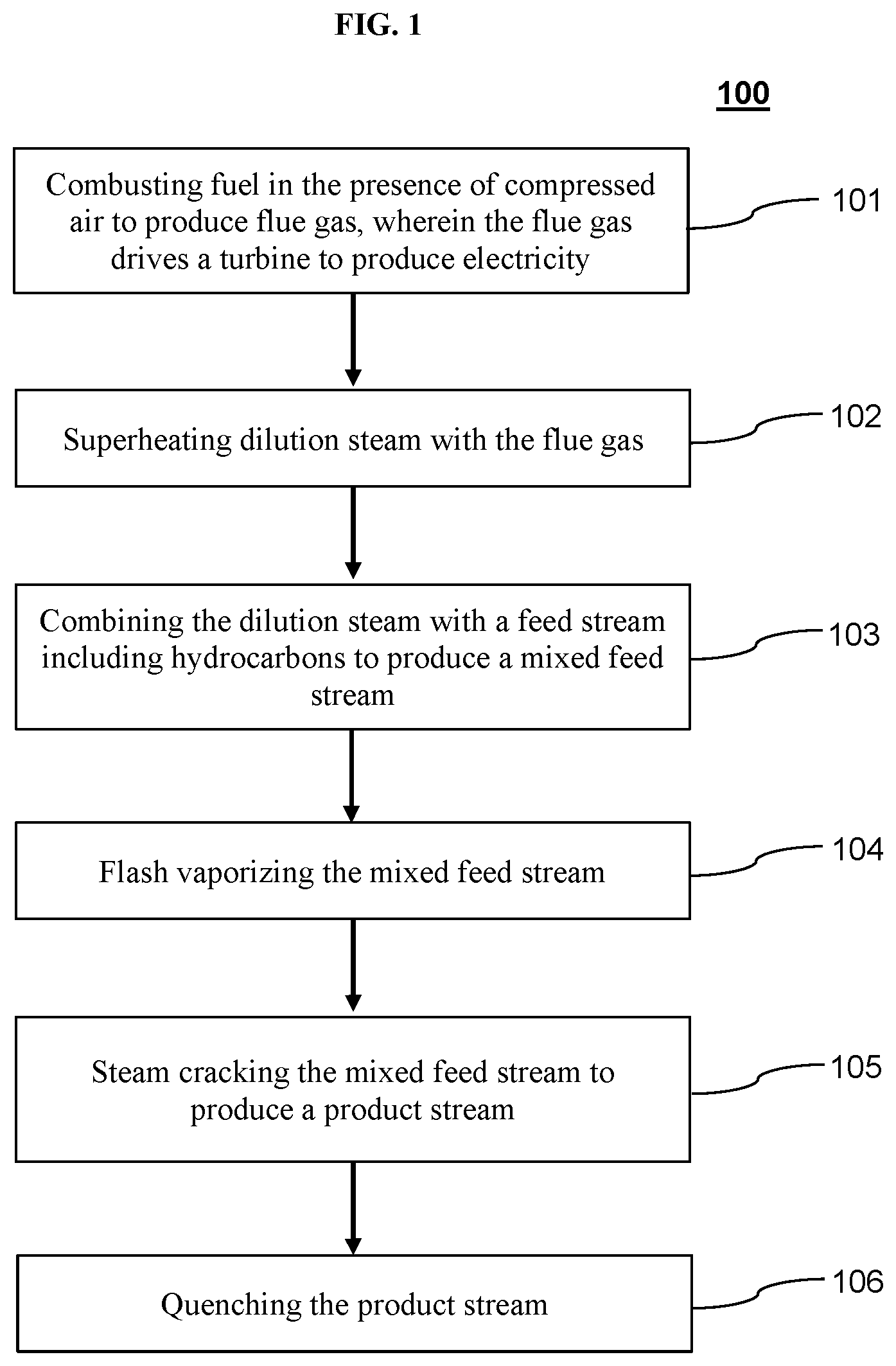
[0015] FIG. 1 depicts a method of superheating dilution steam and generating electricity according to one exemplary embodiment of the disclosed subject matter.
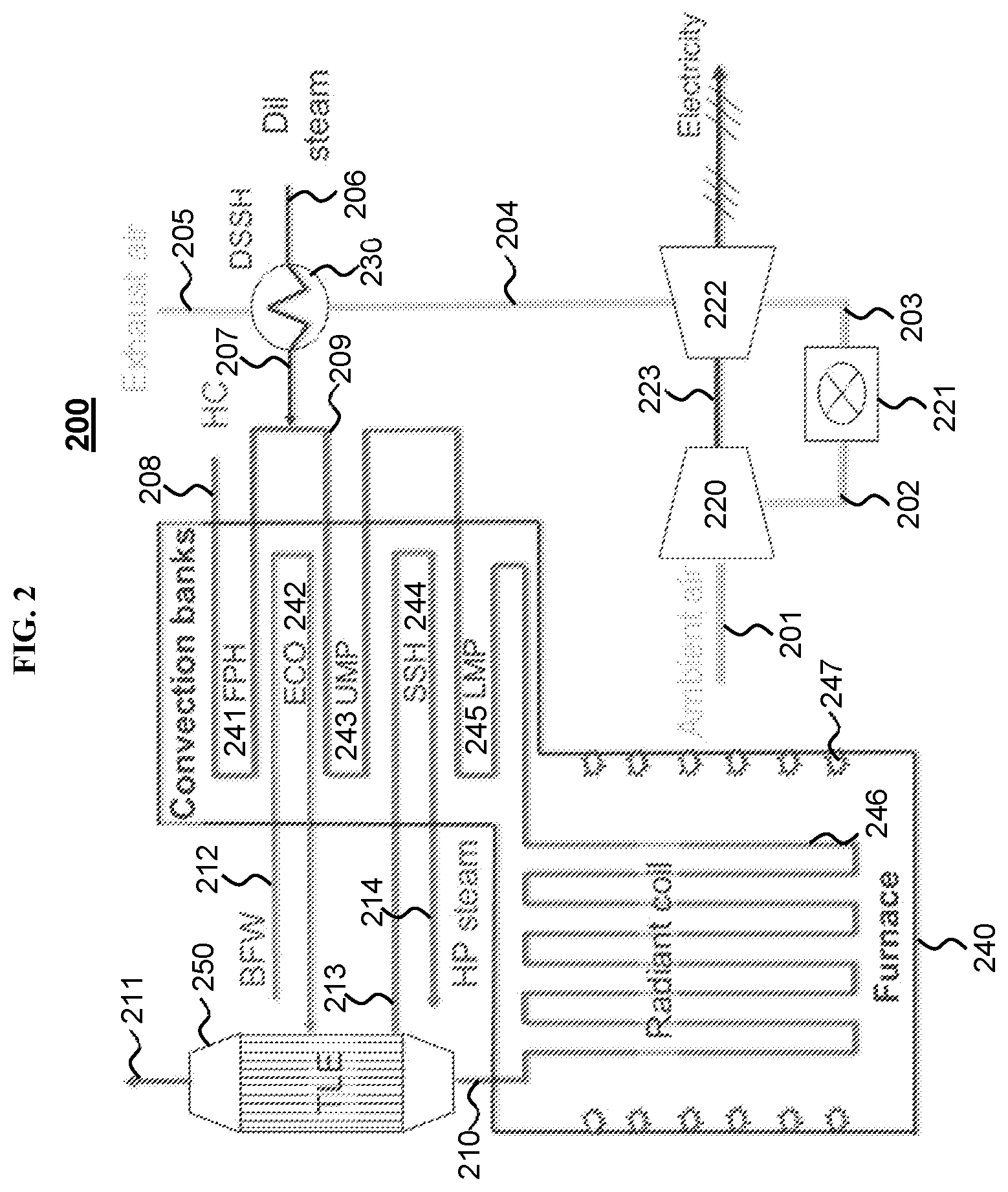
[0016] FIG. 2 depicts a system for superheating dilution steam and generating electricity according to one exemplary embodiment of the disclosed subject matter.
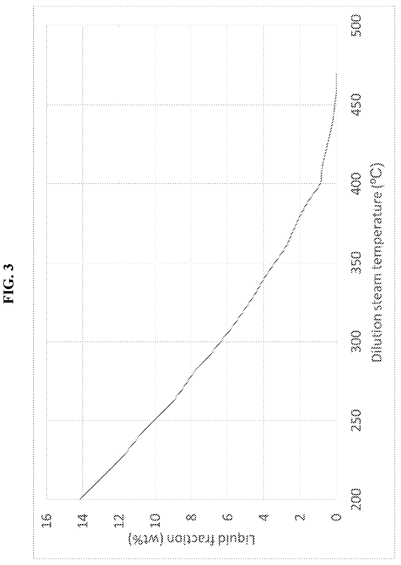
[0017] FIG. 3 provides a graphical representation of the remaining liquid fraction in the feed stream after contact with dilution steam having temperatures from about 200.degree. C. to about 475.degree. C., in accordance with an example embodiment of the disclosed subject matter.
DETAILED DESCRIPTION
[0018] The presently disclosed subject matter provides techniques for superheating dilution steam and generating electricity, including by integrating a steam cracking furnace and a gas turbine generator.
[0019] For the purpose of illustration and not limitation, FIG. 1 is a schematic representation of a method according to a non-limiting embodiment of the disclosed subject matter. In certain embodiments, the method 100 includes combusting fuel in the presence of compressed air to produce a flue gas 101. The air can be ambient air. The fuel can be a suitable fuel for a combustion reaction in the presence of air, for example, the fuel can be a hydrocarbon mixture such as petroleum, gasoline, diesel, natural gas or a fuel gas, which can be produced as a byproduct from an ethylene plant. For example, the fuel gas can contain hydrogen and methane. In certain embodiments, the fuel gas can be syngas, which contains carbon monoxide and hydrogen. The syngas can be produced by the gasification of coal or petroleum products.
[0020] The flue gas can include oxygen, carbon dioxide, steam, and uncombusted fuel. For example, the flue gas can contain from about 5% to about 18%, from about 10% to about 16%, or from about 13% to about 15% oxygen by volume. The flue gas can drive a turbine to generate mechanical work and/or electricity. The flue gas can have a temperature from about 300.degree. C. to about 800.degree. C., from about 350.degree. C. to about 700.degree. C., or from about 400.degree. C. to about 650.degree. C. In certain embodiments, the temperature of the flue gas can be increased, e.g., using a duct burner. For example, the temperature of the flue gas can be increased to about 850.degree. C.
[0021] As used herein, the term "about" or "approximately" means within an acceptable error range for the particular value as determined by one of ordinary skill in the art, which will depend in part on how the value is measured or determined, i.e., the limitations of the measurement system. For example, "about" can mean a range of up to 20%, up to 10%, up to 5%, and or up to 1% of a given value.
[0022] The method 100 can further include superheating dilution steam using the flue gas 102. For example, heat can be transferred from the flue gas to the dilution steam, e.g., in a boiler or heat exchanger. The dilution steam can be superheated to temperatures ranging from about 250.degree. C. to about 750.degree. C., from about 350.degree. C. to about 650.degree. C., or from about 400.degree. C. to about 600.degree. C.
[0023] While superheating the dilution steam, the flue gas can be cooled to a temperature from about 110.degree. C. to about 400.degree. C., or from about 150.degree. C. to about 300.degree. C. The cooled flue gas can be used to preheat the combustion gas used in the steam cracking furnace. Alternatively, the cooled flue gas can be used as a combustion gas in the steam cracking furnace. Additionally or alternatively, the cooled flue gas can be used to generate low pressure steam.
[0024] The method 100 can further include combining the dilution steam with a feed stream including a hydrocarbon feedstock to produce a mixed feed stream 103. The hydrocarbon feedstock can include paraffins, olefins, naphthenes, and/or aromatics. The hydrocarbon feedstock can be light or heavy, i.e., can have a boiling point ranging from about 30.degree. C. to about 500.degree. C. In certain embodiments, the feedstock can be a hydrocarbon stream that is rich in olefins, paraffins, isoparaffins, and/or naphthenes. The feedstock can further include up to about 30 wt-% aromatics. In certain embodiments, the feedstock can contain from about 0 wt-% to about 30 wt-% olefins and/or from about 0 wt-% to about 100 wt-% n-paraffins and/or from about 0 wt-% to about 100 wt-% isoparaffins and/or from about 0 wt-% to about 30 wt-% aromatics. The hydrocarbon feedstock can originate from various sources, for example from natural gas condensates, petroleum distillates, coal tar distillates, peat and/or a renewable source. For example, the hydrocarbon feedstock can include light naphtha, heavy naphtha, straight run naphtha, full range naphtha, delayed coker naphtha, gas condensates, coker fuel oil and/or gas oils, e.g., light coker gas oil and heavy coker gas oil. For further example, the hydrocarbon feedstock can include a hydrocarbon product from the synthesis of syngas, e.g., from Fischer Tropsch synthesis and/or the gasification of hydrocarbon material.
[0025] The dilution steam can be combined with the feed stream in a certain steam to hydrocarbon weight ratio. For example, the weight ratio of steam to hydrocarbons can be from about 0.1:1 to about 1:1. In particular embodiments, the ratio of steam to hydrocarbons is about 0.35:1.
[0026] In certain embodiments, the feed stream can be heated prior to combination with the dilution steam. For example, the feed stream can be heated in the convection section of a steam cracking furnace. The feed stream can be heated to a temperature of about 100.degree. C. to about 200.degree. C. prior to combination with the dilution steam.
[0027] The method 100 can further include flash vaporizing the mixed feed stream 104, i.e., the combination of the hydrocarbon feedstock and the dilution steam. Liquid in the mixed feed stream can be vaporized by contact with the superheated dilution steam. The extent of vaporization can depend in part on the temperature of the superheated dilution steam. FIG. 3 provides a graphical representation of the remaining liquid fraction after contact with dilution steam having temperatures from about 200.degree. C. to about 475.degree. C. In certain embodiments, after flash vaporization, the mixed feed stream can be less than about 35%, less than about 25%, less than about 15%, less than about 10%, less than about 5%, less than about 3%, or less than about 1% liquid. In certain embodiments, greater than about 50%, greater than about 60%, greater than about 70%, or greater than about 80% of the hydrocarbons in the mixed feed stream are vaporized. In certain embodiments, the mixed stream is completely vaporized.
[0028] In certain embodiments, the method can further include heating the mixed feed stream. For example, the mixed feed stream can be heated to a temperature of about 500.degree. C. to about 700.degree. C. In certain embodiments, the mixed feed stream can be further vaporized as it is heated.
[0029] The method 100 can further include steam cracking the mixed feed stream to generate a product stream 105. For example, the mixed feed stream can be steam cracked in the radiant section of a steam cracking furnace. The mixed feed stream can be steam cracked at a temperature from about 600.degree. C. to about 1000.degree. C., from about 700.degree. C. to about 900.degree. C., or from about 750.degree. C. to about 850.degree. C.
[0030] The product stream can include the steam cracking products. For example, the product stream can include light olefins, e.g., ethylene. The product stream can further include other olefins, e.g., propylene and butene, paraffins, e.g., methane, ethane, propane, and butane, dienes, e.g., butadiene, and/or alkynes, e.g., acetylene, methylacetylene and vinylacetylene. In certain embodiments, the product stream can further include other components, for example, hydrogen, carbon monoxide, carbon dioxide, hydrogen sulfide, benzene, toluene, xylenes, ethylbenzene, styrene, pyrolysis gasoline, and/or pyrolysis fuel oil.
[0031] The method 100 can further include quenching the product stream 106. For example, the product stream can be quenched to cool the steam cracking products. The product stream can be cooled to a temperature of about 180.degree. C. to about 500.degree. C.
[0032] In certain embodiments, the product stream can be cooled by indirect heat transfer, e.g., by transferring heat from the product stream to another stream. In certain embodiments, heat can be transferred to a stream containing water, e.g., from a steam drum. In particular embodiments, the water can be preheated prior to quenching the product stream. For example, the water can be preheated in the convection section of the steam cracking furnace. Any steam produced by quenching the product stream can be further superheated, e.g., in the convection section of the steam cracking furnace. In certain embodiments, the product stream can be cooled to a temperature of about 300.degree. C. to about 500.degree. C. by indirect heat transfer, and then subsequently cooled by direct oil quenching, e.g., to a temperature of about 200.degree. C.
[0033] FIG. 2 is a schematic representation of a system according to another non-limiting embodiment of the disclosed subject matter. The system 200 can include a gas turbine generator for combusting air and fuel to produce electrical power. The gas turbine generator can include a compressor 220, a combustion chamber 221, and a turbine 222. The compressor and turbine can be operated on a single shaft 223. A transfer line 201 can be coupled to the compressor for providing air to the compressor. One or more transfer lines 202 can be coupled to the combustion chamber for providing compressed air and fuel for combustion. The combustion can produce a flue gas, which can be used to drive the turbine. A transfer line 203 can transfer flue gas from the combustion chamber to the turbine.
[0034] "Coupled" as used herein refers to the connection of a system component to another system component by any suitable means known in the art. The type of coupling used to connect two or more system components can depend on the scale and operability of the system. For example, and not by way of limitation, coupling of two or more components of a system can include one or more joints, valves, transfer lines or sealing elements. Non-limiting examples of transfer lines include pipes, hose, tubing, and ducting, which can be made of any suitable material, including stainless steel, carbon steel, cast iron, ductile iron, non-ferrous metals and alloys, for example including aluminum, copper, and/or nickel, and non-metallic materials, e.g., concrete and plastic. Non-limiting examples of joints include threaded joints, soldered joints, welded joints, compression joints and mechanical joints. Non-limiting examples of fittings include coupling fittings, reducing coupling fittings, union fittings, tee fittings, cross fittings and flange fittings. Non-limiting examples of valves include gate valves, globe valves, ball valves, butterfly valves and check valves.
[0035] The system 200 can further include a superheater 230, coupled to the gas turbine generator, e.g., via a transfer line 204. A feed line 206 can also be coupled to the superheater for providing steam. The superheater can include one or more heat exchangers. The one or more heat exchangers can be any type suitable for heating gaseous or liquid streams. For example, but not by way of limitation, such heat exchangers include shell and tube heat exchangers, plate heat exchangers, plate and shell heat exchangers, adiabatic wheel heat exchangers, and plate fin heat exchangers. In certain embodiments, the transfer line 204 for transferring flue gas to the superheater can include one or more duct burners to provide additional heat to the flue gas.
[0036] The system can further include a steam cracking furnace 240 coupled to the superheater 230, i.e., via a transfer line 207. An exhaust line 205 can be coupled to the superheater 230 for removing cooled flue gas from the superheater. In certain embodiments, the exhaust line can be coupled to a heat exchanger for heating combustion air, i.e., a combustion gas line coupled to the steam cracking furnace 240. In alternative embodiments, the exhaust line is coupled to the steam cracking furnace and the flue gas is used as combustion gas in the steam cracking furnace.
[0037] The steam cracking furnace 240 can include a radiant section and a convection section. The radiant section can include one or more burners 247, which may be within a firebox. The radiant section can include a radiant coil 246. The convection section can also include one or more coils 241, 242, 243, 244, 245. The coils can be made of any suitable material and have any suitable thickness for the transfer of heat from the furnace. The coils can also include extended surfaces, e.g., fins, to increase heat transfer.
[0038] A feed line 208 can be coupled to the furnace for transferring hydrocarbons to the convection section. In certain embodiments, the feed line can be coupled to a feed preheater 241, i.e., a coil, for heating the hydrocarbons in the convection section. The feed line 208 can be combined with the transfer line 207 from the superheater 230 to form a mixed feed line 209 containing hydrocarbons and dilution steam.
[0039] The mixed feed line 209 can be coupled to a mixed preheater 243, i.e., a coil, for heating the hydrocarbons and dilution steam. This preheater can be termed the "upper mixed preheater." In certain embodiments, the mixed feed line can be coupled to a second mixed preheater 245, i.e., a coil, for further heating the hydrocarbons and dilution steam. This preheater can be termed the "lower mixed preheater." The system 200 can further include a radiant coil 246 downstream from one or more preheaters 241, 243, 245.
[0040] A product line 210 can be coupled to the radiant coil 246 for transferring the steam cracking products from the furnace 240. The product line 210 can be further coupled to a transfer line exchanger 250. The transfer line exchanger can be a heat exchanger, e.g., a shell and tube heat exchanger. In particular embodiments, the transfer line exchanger can be a Borsig transfer line exchanger, an Alstom exchanger, a Shaw quench system, or a KBR millisecond primary quench exchanger.
[0041] The transfer line exchanger 250 can be coupled to a steam drum. A water feed line 212 can provide water to the steam drum. In certain embodiments, the water feed line can transfer steam and/or water from the transfer line exchanger 250. In certain embodiments, the water feed line can be coupled to an economizer 242 upstream from the transfer line exchanger. The economizer can be a coil within the convection section of the steam cracking furnace 240. The product line 210 and the water feed line 212 can exchange heat within the transfer line exchanger. A cooled product line 211 can remove cooled steam cracking products from the transfer line exchanger. A transfer line 213 can transfer the heated water (and steam, if any) to a superheater 244, i.e., a coil, within the convection section of the steam cracking furnace. Another transfer line 214 can transfer steam from the superheater 244 to the steam drum.
[0042] The presently disclosed systems can further include additional components and accessories including, but not limited to, one or more gas exhaust lines, cyclones, product discharge lines, reaction zones, heating elements and one or more measurement accessories. The one or more measurement accessories can be any suitable measurement accessory known to one of ordinary skill in the art including, but not limited to, pH meters, flow monitors, pressure indicators, pressure transmitters, thermowells, temperature-indicating controllers, gas detectors, analyzers and viscometers. The components and accessories can be placed at various locations within the system.
[0043] The methods and systems of the presently disclosed subject matter can provide advantages over certain existing technologies. Exemplary advantages include efficient superheating of dilution steam for steam cracking operations and generation of electricity.
[0044] The following example provides methods of producing superheated dilution steam and electricity in accordance with the disclosed subject matter. However, the following example is merely illustrative of the presently disclosed subject matter and should not be considered as a limitation in any way.
Example: Dilution Steam Generation with and without Gas Turbine
[0045] Three steam cracking processes were simulated. In each simulation, the feed stream was preheated in the convection section of a fired heater. The feed stream was combined with dilution steam to form a mixed feed stream, and the mixed feed stream was fed to an upper mixed preheater and lower mixed preheater. In the first simulation, the dilution steam was not superheated prior to combination with the feed stream. In the second simulation, the dilution steam was superheated in a fired heater (having an efficiency of 90%) to 400.degree. C., 500.degree. C., and 600.degree. C. In the third simulation, the dilution steam was superheated using flue gas from a gas turbine generator to 400.degree. C., 500.degree. C., and 600.degree. C. All three simulations were repeated with light feedstock (i.e., having a boiling point from 30.degree. C. to 260.degree. C.) and heavy feedstock (i.e., having a boiling point from 30.degree. C. to 390.degree. C.). Table 1 shows comparative data from the simulations.
TABLE-US-00001 TABLE 1 Comparative data with no dilution steam superheater, with fired heater, and with gas turbine generator No DSSH DSSH with heater DSSH with gas turbine Light feedstock with BP between 30.degree. C. and 260.degree. C. T.sub.steam 200 400 500 600 400 500 600 Fuel furnace (kg hr.sup.-1) 37590 36800 36530 36030 36800 36530 36030 Fuel heater or gas turbine 0 888 1350 1824 1715 2602 3552 (kg hr.sup.-1) Total fuel (kg hr.sup.-1) 37590 37688 37880 37854 38515 39132 39582 Liquid after flash entering upper 14.2 1 0 0 1 0 0 mixed preheater (% dry) Liquid entering lower mixed 0 0 0 0 0 0 0 preheater (% dry) Electricity (MW) 0 0 0 0 7.27 11.09 15.01 Heavy feedstock with BP between 30.degree. C. and 390.degree. C. T.sub.steam 200 400 500 600 400 500 600 Fuel furnace (kg hr.sup.-1) 37060 36190 35800 35320 36190 35800 35320 Fuel heater or gas turbine 0 888 1350 1824 1715 2602 3552 (kg hr.sup.-1) Total fuel (kg hr.sup.-1) 37060 37078 37150 37144 37905 38402 38872 Liquid after flash entering upper 44.6 30.5 23.6 17.2 30.5 23.6 17.2 mixed preheater (% dry) Liquid entering lower mixed 7.5 2.3 1.0 0.5 2.3 1.0 0.5 preheater (% dry) Electricity (MW) 0 0 0 0 7.27 11.09 15.01
[0046] As shown in Table 1, as the temperature of dilution steam increases, the liquid fraction entering the upper mixed preheater decreases for both the light and heavy feedstock. Additionally, the liquid fraction entering the lower mixed preheater decreases for the heavy feedstock.
[0047] Although compared to the fired heater, the gas turbine generator uses more fuel, it also produces electricity. If the additional fuel is attributed entirely to electricity generation, the electricity is generated with an efficiency between 60% and 80%.
[0048] In addition to the various embodiments depicted and claimed, the disclosed subject matter is also directed to other embodiments having other combinations of the features disclosed and claimed herein. As such, the particular features presented herein can be combined with each other in other manners within the scope of the disclosed subject matter such that the disclosed subject matter includes any suitable combination of the features disclosed herein. The foregoing description of specific embodiments of the disclosed subject matter has been presented for purposes of illustration and description. It is not intended to be exhaustive or to limit the disclosed subject matter to those embodiments disclosed.
[0049] It will be apparent to those skilled in the art that various modifications and variations can be made in the systems and methods of the disclosed subject matter without departing from the spirit or scope of the disclosed subject matter. Thus, it is intended that the disclosed subject matter include modifications and variations that are within the scope of the appended claims and their equivalents.
* * * * *
D00000
D00001
D00002
D00003
XML
uspto.report is an independent third-party trademark research tool that is not affiliated, endorsed, or sponsored by the United States Patent and Trademark Office (USPTO) or any other governmental organization. The information provided by uspto.report is based on publicly available data at the time of writing and is intended for informational purposes only.
While we strive to provide accurate and up-to-date information, we do not guarantee the accuracy, completeness, reliability, or suitability of the information displayed on this site. The use of this site is at your own risk. Any reliance you place on such information is therefore strictly at your own risk.
All official trademark data, including owner information, should be verified by visiting the official USPTO website at www.uspto.gov. This site is not intended to replace professional legal advice and should not be used as a substitute for consulting with a legal professional who is knowledgeable about trademark law.