Conveyed Goods Container Having An Ejection Device And Associated Suspended Conveying Device
HERZOG-LANG; Viktor ; et al.
U.S. patent application number 16/476379 was filed with the patent office on 2020-01-23 for conveyed goods container having an ejection device and associated suspended conveying device. This patent application is currently assigned to TGW Mechanics GmbH. The applicant listed for this patent is TGW Mechanics GmbH. Invention is credited to Viktor HERZOG-LANG, Josef REISCHL.
| Application Number | 20200024074 16/476379 |
| Document ID | / |
| Family ID | 61148183 |
| Filed Date | 2020-01-23 |


View All Diagrams
| United States Patent Application | 20200024074 |
| Kind Code | A1 |
| HERZOG-LANG; Viktor ; et al. | January 23, 2020 |
CONVEYED GOODS CONTAINER HAVING AN EJECTION DEVICE AND ASSOCIATED SUSPENDED CONVEYING DEVICE
Abstract
A conveyed goods container for an overhead conveying device for transporting conveyed goods includes front and rear walls, a bottom abutting on the front and rear walls, and a storage space between the front and rear walls and the bottom, in which the conveyed good is transportable. The bottom forms a first longitudinal edge, which adjoins the front wall, a second longitudinal edge, which adjoins the rear wall, spaced from the first longitudinal edge, a first end edge extending between the first and second longitudinal edges, and a second end edge extending between the first and second longitudinal edges. The conveyed goods container includes a loading and/or unloading opening delimited by the front wall and rear wall and abutting on the first end edge and a side wall stop abutting on the second end edge, against which the conveyed goods can be applied in a transport position.
| Inventors: | HERZOG-LANG; Viktor; (Keltern, DE) ; REISCHL; Josef; (Gunskirchen, AT) | ||||||||||
| Applicant: |
|
||||||||||
|---|---|---|---|---|---|---|---|---|---|---|---|
| Assignee: | TGW Mechanics GmbH Wels AT |
||||||||||
| Family ID: | 61148183 | ||||||||||
| Appl. No.: | 16/476379 | ||||||||||
| Filed: | January 16, 2018 | ||||||||||
| PCT Filed: | January 16, 2018 | ||||||||||
| PCT NO: | PCT/EP2018/050972 | ||||||||||
| 371 Date: | October 11, 2019 |
| Current U.S. Class: | 1/1 |
| Current CPC Class: | B65G 19/025 20130101; B65G 9/004 20130101; B65G 9/002 20130101; B65G 47/61 20130101 |
| International Class: | B65G 9/00 20060101 B65G009/00; B65G 47/61 20060101 B65G047/61 |
Foreign Application Data
| Date | Code | Application Number |
|---|---|---|
| Jan 16, 2017 | DE | 20 2017 100 206.3 |
Claims
1-66. (canceled)
67. A conveyed goods container (1) for an overhead conveying device (3) for transporting conveyed good (5), which is adjustable between an opened position and a closed position, comprising a front wall (65), a rear wall (67), a bottom (11) abutting on the front wall (65) and rear wall (67), a storage space (69) between the front wall (65), the rear wall (67) and the bottom (11), which is accessible in the opened position and in which the conveyed good (5) can be transported, a frame (31), by means of which the conveyed goods container (1) is adjustable between the opened position and the closed position wherein the front wall (65), the rear wall (67) and the bottom (11) of the conveyed goods container (1) comprise a flexible material (33) suspended on the frame (31), wherein the storage space (69) is of reduced volume in the closed position, wherein the bottom (11) has a first longitudinal edge (71), which is adjoined by the front wall (65), a second longitudinal edge (73) extending spaced apart from the first longitudinal edge (71), which is adjoined by the rear wall (67), a first end edge (75) extending between the first longitudinal edge (71) and the second longitudinal edge (73), a second end edge (77) extending between the first longitudinal edge (71) and the second longitudinal edge (73), and wherein the conveyed goods container (1) in its opened position comprises a loading and/or unloading opening (79, 79') delimited by the front wall (65) and rear wall (67) and abutting on the first end edge (75), through which the conveyed goods container (1) can be loaded and/or unloaded with the conveyed good (5), if the conveyed goods container (1) has been adjusted into the opening position, wherein the flexible material (33) is at least partially planked for the at least partial stiffening of the conveyed goods container (1), wherein the planking forms a sliding surface (29), and wherein the bottom (11) forms a receiving surface (133) ending in the loading and/or unloading opening (79, 79'), on which the conveyed good (5) can be stored and which extends between the two longitudinal edges (71, 73) and the two end edges (75, 77) and which defines the sliding surface (29).
68. The conveyed goods container according to claim 67, wherein the storage space (69) is formed between the bottom (11), the front wall (65), the rear wall (67) and a side wall stop (81) disposed opposite the loading and unloading opening (79, 79').
69. The conveyed goods container according to claim 67, wherein the conveyed goods container (1) comprises a side wall stop (81) abutting on the second end edge (77), against which the conveyed goods (5) can be applied in a transport position.
70. The conveyed goods container according to claim 67, wherein the conveyed goods container (1) has an opening delimited by the front wall (65) and rear wall (67) and abutting on the second end edge (77), which forms in particular a loading and/or unloading opening (79').
71. The conveyed goods container according to claim 67, wherein the first longitudinal edge (71) forms a first folding edge (83) and the second longitudinal edge (73) forms a second folding edge (85).
72. The conveyed goods container according to claim 71, wherein a width of the bottom (11) between the folding edges (83,85) is between 5 mm and 800 mm.
73. The conveyed goods container according to claim 67, wherein the bottom (11) is inclinable between the transport position, in which the conveyed good (5) is storable within the conveyed goods container (1), and a discharge position, in which the conveyed good (5) is discharged from the conveyed goods container (1).
74. The conveyed goods container according to claim 67, wherein the bottom (11) in a suspended state of the conveyed goods container (1) in the transport position comprises a storage incline (15), in particular a storage incline (15) toward the side wall stop (81) of an at least partially closed vertical side (9), between the first end edge (75) and second end edge (77).
75. The conveyed goods container according to claim 67, wherein the conveyed goods container (1) comprises an opened top side (19) opposite the bottom (11) for loading with the conveyed good (5).
76. The conveyed goods container according to claim 67, wherein the front wall (65), the rear wall (67) and the side wall stop (81) form three at least partially closed vertical sides (9) of the conveyed goods container (1).
77. The conveyed goods container according to claim 67, wherein the flexible material (33) comprises at least one of the following electrical properties: an electrical surface resistance of greater than or equal to 10.sup.6 ohm, a surface resistivity between 10.sup.7 ohm/square and 10.sup.12 ohm/square.
78. The conveyed goods container according to claim 77, wherein the flexible material (33) comprises a surface resistivity of 2.times.10.sup.7 ohm/square.
79. The conveyed goods container according to claim 67, wherein the flexible material is antistatic, in particular comprises a surface resistivity between 10.sup.9 ohm/square and 10.sup.12 ohm/square.
80. The conveyed goods container according to claim 67, wherein the flexible material (33) comprises electrically conductive fibers (121) and/or electrically conductive wires.
81. The conveyed goods container according to claim 80, wherein the electrically conductive fibers (121) are inserted into the flexible material at a distance of between 1 mm and 15 mm, preferably about 8 mm.
82. The conveyed goods container according to claim 80, wherein the electrically conductive fibers (121) comprise a carbon fiber material.
83. The conveyed goods container according to claim 67, wherein the conveyed goods container (1) comprises a tripping lever (25) connected to the bottom (11).
84. An overhead conveying device (3) having a conveyed goods container (1) for transporting conveyed goods (5), wherein the conveyed goods container (1) is formed according to claim 67.
85. A loading station (87) having the conveyed goods container (1) according to claim 67, for manual or automated loading of the conveyed goods container (1) with a conveyed good (5), comprising an overhead conveying device (3) for transporting the conveyed goods container (1) into the loading station (87) and transporting the conveyed goods container (1) out of the loading station (87), an opening device (89, 107) for adjusting the conveyed goods container (1) between the closed position, in which the storage space (69) is inaccessible and/or of reduced volume, and the opened position, in which the storage space (69) is accessible, and for loading the conveyed goods container (1), which has been adjusted into the opened position, i) either a loading device (91), ii) or a feeding device (93) driven in an automated manner, (iii) or the loading device (91) and the feeding device (93) driven in an automated manner, and wherein the loading device (91) or the feeding device (93) defines a working plane (95), which extends essentially in alignment with the bottom (11) of the conveyed goods container (1) or slightly above the bottom (11) of the conveyed goods container (1), so that an essentially continuous transition between the working plane (95) and the bottom (11) is formed.
86. The loading station (87) according to claim 85, wherein a locking device (97) for temporarily fixing the conveyed goods container (1) during a loading operation is additionally provided.
87. The loading station according to claim 85, wherein a guide profile (99) for guiding a frame (31) of the conveyed goods container (1) is additionally provided.
88. The loading station according to claim 85, wherein the opening device (107) of the loading station (87) comprises at least one bag opening flap (101) movable by means of a drive (103) between a first flap position and a second flap position for adjusting the conveyed goods container (1) between the closed position and the opened position.
89. The loading station according to claim 88, wherein the bag opening flap (101) in the second flap position comprises a guide surface (115) for guiding the frame (31) during a leaving of the loading station (87), which extends in a direction of movement of the conveyed goods container (1).
90. Loading station according to claim 88, wherein the frame (31) in the second flap position is fixed in a friction fit between the bag opening flap (101) and the guide profile (99).
91. An unloading station (105) having the conveyed goods container (1) according to claim 67, for unloading the conveyed goods container (1) loaded with at least one conveyed good (5), comprising an overhead conveying device (3) for transporting the conveyed goods container (1) into the unloading station (105) and transporting the conveyed goods container (1) out of the unloading station (105), an opening device (89, 107) for adjusting the conveyed goods container (1) between the closed position, in which the conveyed good (5) is stowed or stowable in the storage space (69), and the opened position, in which the conveyed good (5) is accessible in the storage space (69), and an unloading device (109) for unloading the conveyed goods container (1), which has been adjusted into the opened position, with the help of which the bottom (11) is inclinable between a transport position, in which the conveyed good (5) is stored in the storage space (69), and a discharge position, in which the conveyed good (5) is discharged from the storage space (69).
92. The unloading station according to claim 91, wherein a locking device (97) for temporarily fixing the conveyed goods container during an unloading operation is additionally provided.
93. The unloading station according claim 91, wherein a guide profile (99) for guiding a frame (31) of the conveyed goods container (1) is additionally provided.
94. The unloading station according to claim 91, wherein the opening device (107) comprises at least one bag opening flap (101) movable by means of a drive (103) between a first flap position and a second flap position for adjusting the conveyed goods container (1) between the closed position and the opened position.
95. The unloading station according to claim 94, wherein the bag opening flap (101) in the second flap position comprises a guide surface (115) for guiding the frame (31) during a leaving of the unloading station (105) which extends in a direction of movement of the conveyed goods container (1).
96. The unloading station according to claim 94, wherein the frame (31) in the second flap position is fixed in a friction fit between the bag opening flap (101) and the guide profile (99).
97. The unloading station according to claim 91, wherein the unloading device (109) comprises a pusher-dog mechanism (21), by means of which the bottom (11) is adjustable between the transport position and the discharge position.
98. The unloading station according to claim 91, wherein the unloading device (109) comprises a bag unloading device (113), in particular bag unloading brackets, movable by means of an unloading drive (111) between an initial position and an actuation position for adjusting the bottom (11) between the transport position and the discharge position.
99. An overhead conveying system (117) comprising an overhead conveying device (3) having a conveyed goods container (1) for transporting conveyed goods (5), a loading station (87) for manual or automated loading of a conveyed goods container (1) and an unloading station (105) for unloading a conveyed goods container (1) loaded with at least one conveyed good (5), wherein the overhead conveying device (3) is formed according to claim 67.
100. The overhead conveying system according to claim 99, further comprising a suspended support (119) conveyable in a direction of movement of the conveyed goods container (1), each of which is fixable in the loading station (87) and/or the unloading station (105) by means of a locking device (97).
101. The overhead conveying system according to claim 100, wherein the locking device (97) is either releasable or fixable by means of a fixing plate (123) which is adjustable between an initial position and a fixed position.
102. A method for unloading a conveyed good (5) from a conveyed goods container (1), in particular the conveyed goods container (5) according to claim 67, in which the conveyed goods container (1) is transported on an overhead conveying device (3) to an unloading station (105) into a provisioning position and at the unloading station (105) i) in a first step is adjusted by means of an opening device (89, 107) or by an operator from a closed position, in which the conveyed good (5) is stowed in the storage space (69), into an opened position, in which the conveyed good (5) is accessible in the storage space (69), and subsequently ii) in a second step the bottom (11) is inclined by means of an unloading device (109) from a transport position, in which the conveyed good (5) is stored in the storage space (69), into a discharge position, in which the conveyed good (5) is discharged from the storage space (69), so that in the discharge position a rear region of the bottom positioned opposite the loading and/or unloading opening (79) is positioned higher than a front region of the bottom, and the conveyed good (5) slides out of the conveyed goods container (1).
103. The method for the manual or automated loading of a conveyed goods container (1) according to claim 67, with at least one conveyed good (5), in which the conveyed goods container (1) is transported on an overhead conveying device (3) to a loading station (87) and provisioned in a provisioning position in front of a loading device (91) or a feeding device (93), wherein i) in a first step the conveyed goods container (1) is adjusted by means of an opening device (89, 107) or by an operator from a closed position, in which the storage space (69) is inaccessible and/or reduced in volume, into an opened position, in which the storage space (69) is accessible, and subsequently ii) in a second step the conveyed good (5) is brought by the loading device (91) or the feeding device (93) into the storage space (69) of the conveyed goods container (1), which has been adjusted into the opened position, wherein a working plane (95) at the loading device (91) or the feeding device (93) is essentially in alignment with the bottom (11) of the conveyed goods container (1) or extends slightly above the bottom (11) of the conveyed goods container (1).
Description
FIELD OF THE INVENTION
[0001] The invention relates to a conveyed goods container for transporting piece good according to the preamble of claim 1, an associated overhead conveying device as well as a overhead conveying system for transporting, a loading and an unloading station for loading and unloading, a method for loading and unloading the conveyed goods container as well as a use of a flexible (non-rigid) material for the conveyed goods container.
PRIOR ART
[0002] In automated article stores, production plants and during article transport, such as for example in mail-order retail, it is required to accommodate conveyed good in conveyed goods containers in a manner that is, if possible, automated. In these conveyed goods containers the articles can be stored before their being delivered and thus get to the station where they are packaged for onward transport to the customer. The transport within the stores is typically done via overhead conveying devices. In this case, the conveyed goods containers are often bags which are manufactured like cloth bags and are hooked at the top into a rail system using a type of wire arm. Such a conveyed goods container is known for example from WO 2014/012965 A1. The side wall elements of the former are controlled via a rod assembly in such a way that the side wall elements connected to one another via a connection region can be flipped open. In the area of a loading station the containers are in addition transitioned into a horizontal or inclined position.
[0003] Comparable conveyed goods containers and associated overhead conveying devices are known for example from DE 10 2004 018 569 A1, EP 2 130 968 A1 or EP 2 196 415 A. The transport bags described therein consist of flexible materials in the form of a loop, in which the conveyed good is held. For loading, these transport bags are opened at the top in order to be able to insert the conveyed good into the loop. An unloading is done by the conveyed good either being taken or discharged sideways from the loop or the loop being opened at the bottom, e.g. in accordance with EP 2 130 968 A1. Furthermore, a conveyed goods carrier is known from DE 103 54 419 A1 which comprises a relatively stiff and flat plastic wall with a cutout opening for loading and unloading conveyed good.
[0004] Other conveyed goods containers are manufactured like hanging, flat tubs of plastic unilaterally coated with elastic fabrics, which clamps conveyed good.
[0005] It is known to load such conveyed goods containers in a mechanized manner and to unload them manually. A transporting stage is determined by the slowest process, which depends, inter alia, on the quantity of conveyed good. In particular a high number of individual conveyed goods can slow down the loading and/or unloading. For example the unloading and/or the assembling of dismantled transport containers can determine the maximum possible transporting stage. EP 2 686 258 B1 relates to an overhead conveying system having a transport bag for automated unloading of a loaded piece good and having an unloading station. The transport bag comprises a horizontal bottom, on which the piece good can be stored for the purpose of being transported. The bottom cooperates with a lifting device adapted to lift the bottom of the transport bag, which is loaded with at least one piece good, when the transport bag is in an unloading position in a vertical direction in such a way that the at least one piece good can be centrally pushed out by means of a pushing device through an end wall of a basic body of the transport bag and wherein the pushing device comprises a slide which engages with an interior of the basic body through a different end wall of the basic body where the at least one piece good is located when the bottom is lifted. This means that for unloading are required the two opposite, opened end walls, the bottom which is liftable in the vertical direction as well as the slide of the pushing device reaching through one of the end walls.
SUMMARY OF THE INVENTION
[0006] Starting from this prior art the object underlying the present invention is to create a conveyed goods container which allows a transporting stage which is as short as possible, can be loaded and unloaded in a simple manner and/or allows a trouble-free transport and yet has a structure which is as simple as possible.
[0007] In a conveyed goods container for an overhead conveying device for transporting conveyed good, comprising a front wall, a rear wall, a bottom abutting on the front wall and rear wall, a storage space between the front wall, the rear wall and the bottom, in which the conveyed good can be transported, wherein the bottom forms a first longitudinal edge which is adjoined by the front wall, a second longitudinal edge extending spaced apart from the second longitudinal edge, which is adjoined by the rear wall, a first end edge extending between the first longitudinal edge and the second longitudinal edge, a second end edge extending between the first longitudinal edge and the second longitudinal edge, the object is achieved by the conveyed goods container comprising a loading and/or unloading opening delimited by the front wall and rear wall and abutting on the first end edge. The conveyed goods container is configured to be adjustable between a closed position, in which the storage space is inaccessible and/or of reduced volume, and an opened position, in which the storage space is accessible. In particular the conveyed goods container can comprise a frame, by means of which the conveyed goods container is adjustable between the closed position and the opened position. In the closed position a conveyed good inserted into the storage space can be transported. In the opened position the conveyed goods container can be loaded and/or unloaded. In particular the conveyed goods container comprises, in its opened position, a loading and/or unloading opening delimited by the front wall and rear wall and abutting on the first end edge. In the opened position the bottom extends essentially horizontally between the first longitudinal edge and the second longitudinal edge.
[0008] According to the invention it is provided that the loading and/or unloading opening abuts on the first end edge, which, however, does not exclude a side wall extending between the front wall and rear wall above the loading and/or unloading opening. It must merely be ensured that the loading and/or unloading opening is sized in such a way that the largest conveyed good can be moved through the loading and/or unloading opening without colliding with the side wall. In particular it is advantageous that for unloading of the conveyed goods container a conveyed good resting on the bottom can be done through the unloading opening and over the first end edge. If loading of the conveyed goods container is also done through the loading opening, the conveyed good can be done through the loading opening and over the first end edge. In this case, the first end edge can also serve as a tipping edge, enabling a reliable unloading and/or loading of the conveyed goods container. In addition, the conveyed goods container can be manufactured at particularly low cost.
[0009] Preferably the frame has a rectangular outline with two longitudinal sides and two short sides, wherein the front wall and the rear wall are each positioned in an articulated manner at the longitudinal sides of the frame. The frame is tiltable around an axis relative to a suspended support, by means of which the conveyed goods container can be hung on an overhead conveying device. The suspended support is mounted at one of the longitudinal sides, in particular at the longitudinal side at which the front wall is positioned. Preferably the axis extends through the longitudinal side of the frame at which the front wall is positioned.
[0010] According to one embodiment of the invention it is provided that the conveyed goods container comprises a side wall stop abutting on the second end edge, against which the conveyed good can be applied in a transport position.
[0011] The additional side wall stop can hold the conveyed good in the storage space during transport. While typical conveyed goods in the transport position of a respective conveyed goods container are held between the front wall, rear wall and the bottom with sufficient holding force, it proves advantageous if conveyed goods deviating from standard measurements or standard forms are additionally held by the side wall stop. Thus, an accidental dropping of the conveyed good out of the conveyed goods container during a transport can be avoided by means of the side wall stop. Further, the conveyed good can be pushed into the conveyed goods container in a simple manner until the former rests against the side wall stop. An accidental dropping out of the conveyed good during any too dynamic loading operation can thus be prevented with certainty. Preferably the bottom is inclined toward the side wall stop in order to achieve an even higher level of safety during loading and transport. According to one design of the invention it is also possible that the conveyed goods container comprises an opening delimited by the front wall and rear wall and abutting on the second end edge. This opening can also be used as a loading and/or unloading opening.
[0012] In this case, the conveyed goods container is formed without an additional side wall stop. This is because it has become apparent that typical conveyed goods in the transport position of the conveyed goods container can be held with sufficient holding force between the front wall, rear wall and the bottom. Therefore, manufacturing costs of the conveyed goods container can be reduced to a minimum, as an additional process step in the manufacturing of the side wall stop becomes obsolete. Such a side wall stop is especially cut from a separate material web and joined with the at least one material web for the front wall, rear wall and the bottom, in particular sewn to the front wall and the bottom or the rear wall and the bottom.
[0013] Relinquishing the side wall stop may seem trivial at first sight, but in view of the enormously high number of pieces in a logistics plant it reduces investment costs considerably.
[0014] If the opening is used optionally as a loading and/or unloading opening, the conveyed goods container can be loaded and/or unloaded unrestrictedly from both sides. The conveyed goods container in the loading station can be loaded either from the first side or from the second side. In a preferred embodiment there is a stationary wall on a side opposite the loading side, which is sized to cover the unloading opening between the front wall and rear wall. The height of the wall can vary, however, at least formed sufficiently downward for the second end edge to be positioned somewhat higher than the bottom edge of the wall.
[0015] It also proves advantageous if the conveyed goods container is for example loaded from the first side in the loading station and unloaded from the second side in the unloading station. This is because it has become apparent that when loading the conveyed goods container from the first side the conveyed good ends up being positioned in the rear region of the bottom, and thus closer to the unloading opening than to the loading opening. Therefore, the conveyed goods container can be unloaded more quickly. One exemplary embodiment provides that the first longitudinal edge forms a first folding edge and the second longitudinal edge forms a second folding edge. The folding edges serve as material hinges to which the bottom is hinged and enable a relative shift between the front wall and rear wall. Thus, the storage space and/or the holding capacity can be increased and decreased. The conveyed goods container can be used for conveyed goods of different sizes and/or be buffered empty in a very space-saving manner or be transported back.
[0016] It is possible for a width of the bottom between the folding edges to be between 5 mm and 800 mm. The width of the bottom between the folding edges can be varied. Therefore, specially adapted conveyed goods containers are conceivable.
[0017] Alternatively it can be provided that the bottom is inclinable between the transport position, in which the conveyed good is storable within the conveyed goods container, and a discharge position, in which the conveyed good is discharged from the conveyed goods container. In the transport position the conveyed good can be brought in contact with the side wall stop. To that end the bottom in the transport position can be inclined toward the side wall stop. By changing the inclination of the bottom into the discharge position toward the loading and/or unloading opening, the unloading of the conveyed goods container can be made simpler and/or easier. Ideally, the conveyed good can slide out of the conveyed goods container by itself.
[0018] Further, it is possible that the bottom in a suspended state of the conveyed goods container in the transport position comprises a storage incline between the first end edge and second end edge. In particular, according to one embodiment of the conveyed goods container having a side wall stop the storage incline is formed toward the side wall stop of an at least partially closed vertical side. The at least partially closed vertical side can comprise and/or form the side wall stop. During the transport due to the storage incline the conveyed good automatically slides toward the at least partially closed vertical side and rests against the latter, put away safely. An accidental dropping of the conveyed good out of the conveyed goods container can thus be avoided with certainty or at least be made substantially more difficult.
[0019] Another possible variant provides that the bottom in the discharge position comprises a discharge incline toward the loading and/or unloading opening of an at least partially opened vertical side. The discharge incline facilitates the unloading of the conveyed goods container, wherein the discharge incline is ideally sized in such a way that a parallel component of the force of gravity of the conveyed good standing on the bottom overcomes a static friction and the conveyed good thus slides out of the conveyed goods container by itself. Because of the discharge incline, i.e. the inclining of the bottom toward the loading and/or unloading opening so that the conveyed good can unrestrictedly slide out of the conveyed goods container, the first end edge abutting on the loading and/or unloading opening is positioned lower than the second end edge disposed opposite the former.
[0020] Preferably the bottom can form a receiving surface ending in the loading and/or unloading opening (if according to a first embodiment there is a side wall stop) or in the loading and/or unloading openings (if according to a second embodiment a side wall stop is relinquished), on which the conveyed good can be mounted. The receiving surface can also define a sliding surface. In particular the receiving surface extends between the two longitudinal edges and the two end edges. The receiving surface abuts immediately on the first end edge and second end edge. The conveyed good can be slidably mounted on the sliding surface of the bottom. This facilitates a loading and unloading of the conveyed goods container, and in particular can the conveyed good be pushed into the conveyed goods container and pulled out of it again in a particularly simple manner. Depending on the current incline of the bottom by a power-assisted sliding movement or, if applicable, in an externally powerless sliding movement, i.e. by itself.
[0021] Preferably it is conceivable that the conveyed goods container comprises the opened top side opposite the bottom for filling with the conveyed good. In this way the conveyed goods container can be loaded and/or unloaded either through the loading and/or unloading opening or via the opened top side. It is in particular conceivable to load the conveyed goods container via the opened top side, wherein in this case the conveyed goods container is preferably already in the transport position, and to carry out the unloading via the loading and/or unloading opening. To that end the bottom can be set to the discharge position.
[0022] In another alternative the front wall, rear wall and the side wall stop can form three at least partially closed vertical sides of the conveyed goods container. The front wall, rear wall and side wall can for example have an identical cut, which allows a particularly simple structure of the conveyed goods container. A closed vertical side can for example be understood to mean a textile or a foil extending in a vertical direction of the conveyed goods container. Partially closed can be understood to mean that the textile and/or the foil extends at least in some regions in a vertical direction of the conveyed goods container. In particular it is conceivable that a partially closed vertical side extends starting at the longitudinal edges and/or end edges across a part of a total height of the conveyed goods container. This improves access from the top to the conveyed good without reducing safety during transport. It is self-evident that optionally only the side wall can form one of the three partially closed vertical sides while the front wall and rear wall each form a completely closed vertical side.
[0023] Another exemplary embodiment of the conveyed goods container provides that the front wall, rear wall and/or the bottom of the conveyed goods container comprise a flexible (non-rigid) material suspended on a frame. By means of the frame and the flexible material as well as the bottom the storage space can be tentered. A flexible material can be understood to mean a fabric, a foil, a braid, a knitted fabric, a weave and/or similar. By means of the suspended flexible material a very light and flexible-use conveyed goods container can be provided.
[0024] Further, it is possible for the conveyed goods container to hold, in particular clamp, the conveyed good in the transport position between the bottom and the flexible material. The flexible material is preferably supple and can, if applicable, have elastic properties. In this way the conveyed good can be surrounded at least in some regions, for example at corners and edges, in a tight-fitting manner by the flexible material. In this way a form and/or friction fit for holding the conveyed good within the conveyed goods container can be caused. The form and/or friction fit can be intensified by a gravity of the conveyed good, wherein an autoinhibition can occur.
[0025] The flexible material can be at least partially planked for stiffening the conveyed goods container. Due to the planking a more stable conveyed goods container can be provided. The planking can be adapted to different transporting tasks and for example fortify heavily strained regions, in particular of the flexible material.
[0026] The flexible (non-rigid) material can preferably be designed at least in some regions electrically conductive in such a way that an electrostatic charge can be counteracted. To that end it can for example have a surface resistance of greater than or equal to 10.sup.6 ohm and/or a surface resistivity between 10.sup.7 ohm/square and 10.sup.12 ohm/square. Already in this range an electrostatic charge can be avoided very well, wherein due to the comparatively weak conductivity properties which are important for the transport, the loading and unloading, such as elasticity, foldability and stability, are not affected. In this way the conveyed goods container can be used for the most varied conveyed goods, i.e. also conveyed goods which are susceptible to electrostatic discharges. Further, an undesired adherence of the conveyed good within the conveyed goods container by means of electrostatic forces can be avoided. In this way the conveyed goods container can be more easily loaded and unloaded. A surface resistance and/or surface resistivity can be understood to mean an electric resistance which is measurable at a specific distance between two point-shaped electrodes. A surface resistivity can be understood to mean a resistance measured between two longitudinal electrodes which are arranged in parallel opposite each other, wherein a length of the electrodes corresponds to a distance of the electrodes to each other. Specifically the surface resistivity can be 2.times.10.sup.7 ohm/square. In order to reliably avoid an electrostatic charge, a material is used which is antistatic. Particularly preferably in this case the surface resistivity can be between 10.sup.9 ohm/square and 10.sup.12 ohm/square.
[0027] To that end it is also conceivable that the flexible material comprises electrically conductive fibers and/or electrically conductive wires. Via the electrically conductive fibers and/or wires, electric energy can be discharged for preventing the electrostatic charge. To that end the fibers and/or wires can be connected to a ground.
[0028] Preferably the electrically conductive fibers and/or wires can be inserted into the flexible (non-rigid) material at a distance of between 1 mm and 15 mm, preferably about 8 mm. When the distance is greater, comparatively few wires and/or fibers will be needed. For the special tasks of the conveyed goods container it turned out that a distance of between 1 and 15 mm still ensures a sufficiently good discharge of the load for preventing the electrostatic charge. A distance of about 8 mm has turned out to be a good compromise between saving material and preventing the electrostatic charge.
[0029] Particularly preferably the electrically conductive fibers can comprise a carbon fiber material. The carbon fiber material can be woven into the flexible (non-rigid) material and/or positioned on a surface. Any flexible properties are not or only insubstantially affected by the carbon fiber material, while at the same time a stability can be increased and the electrical conductivity can be provided.
[0030] It is finally conceivable that the conveyed goods container comprises a tripping lever connected to the bottom. Via an optional tripping lever the bottom can be adjusted between the transport position and the discharge position in a mechanized or manual manner. In a simple case the bottom can thereby be unilaterally lifted and inclined. Without the tripping lever being actuated, the bottom comprises the storage incline, and, by the tripping lever being actuated, the bottom comprises the discharge incline toward the loading and/or unloading opening. In this way the conveyed good can be discharged from the conveyed goods container in a mechanized and/or manual manner.
[0031] The object is further achieved in an overhead conveying device having a conveyed goods container for transporting conveyed goods described above. By means of the overhead conveying device the conveyed goods container can be transported to a loading station for loading the conveyed goods container and transported away from the latter and/or transported to an unloading station for unloading the conveyed goods container and transported away from the latter as well as between the loading station and the unloading station. As to the rest, the advantages described above become apparent.
[0032] Moreover the object is in a loading station for manual or automated loading of a conveyed goods container with a conveyed good, having a front wall, a rear wall, a bottom abutting on the front wall and rear wall, a storage space between the front wall, the rear wall and the bottom, in which the conveyed good is transportable, which loading station comprises an overhead conveying device for transporting the conveyed goods container into the loading station and transporting the conveyed goods container out of the loading station, an opening device for adjusting the conveyed goods container between a closed position, in which the storage space is inaccessible and/or of reduced volume, and an opened position, in which the storage space is accessible, and, for loading the conveyed goods container, which has been adjusted into the opened position, either a loading device or a (mechanized) feeding device driven in an automated manner or the loading device and the feeding device, wherein the loading device or the feeding device defines a working plane extending essentially in alignment with the bottom of the conveyed goods container or slightly above the bottom of the conveyed goods container, so that an essentially continuous transition is formed between the working plane and the bottom. In this case, the term "essentially continuous transition" is to be understood to mean that while a limited progressive ratio between the working plane and the bottom is possible, the former is, in this case, so small that even a small conveyed good is not thrown off onto the bottom in free fall. Rather, the conveyed good can be tilted from the working plane onto the bottom.
[0033] In particular, for a manual loading, the working plane can be formed by a supporting table. On the latter, a manual shifting of the conveyed good through the loading opening into the storage space of the conveyed goods container can be done in a simple manner. To that end the conveyed goods container is first adjusted into the opened position. According to an alternative, however, the working plane can also be understood to mean an imaginary plane formed by means of a mechanization, for example a robot. Along the imaginary working plane the conveyed good can be moved through the loading opening into the storage space of the conveyed goods container by means of the robot. It is also possible that the conveyed good is moved by a conveying device, for example a belt conveyor, through the loading opening into the storage space of the conveyed goods container. The conveying plane is in this case formed by the working plane. According to these embodiments, too, the conveyed good is not "thrown off" but carefully put down. According to another embodiment a pusher and a supporting table can be used, wherein the conveyed good rests on the working plane and is transported through the loading opening into the storage space of the conveyed goods container in a mechanized manner.
[0034] The opening device can comprise a mechanization, by means of which the conveyed goods container is adjustable between the opened position and the closed position. In a particularly simple design the opening device comprises merely the frame (of the conveyed goods container), which can be seized and deviated for a manual actuation. To that end the frame can be mounted at the conveyed goods container deviatably along a swivel axis. For an automatic actuation the opening device can comprise a mechanization acting on the frame which causes the dislocation, preferably deviation, of the frame.
[0035] To increase a safety of operation, a locking device for temporarily fixing the conveyed goods container during a loading operation can additionally be provided. By means of the locking device the conveyed goods container can be positioned and/or maintained in a desired position. An accidental moving of the conveyed goods container out of the loading station during a loading operation can be prevented.
[0036] In a preferred exemplary embodiment the loading station can additionally comprise a guide profile for guiding a frame of the conveyed goods container. At the frame the vertical sides of the conveyed goods container can be suspended and/or tentered. A guiding of the frame also causes a precise desired path of motion of the entire conveyed goods container. The conveyed goods container can therefore be dislocated and/or positioned in a desired manner within the loading station. The guide profile can alternatively or additionally be designed for opening the conveyed goods container.
[0037] Further, it can be provided that the opening device of the loading station comprises at least one bag opening flap movable by means of a drive between a first flap position and a second flap position for adjusting the conveyed goods container between the closed position and the opened position. The bag opening flap preferably acts on the frame of the conveyed goods container. To that end the bag opening flap can be deviatable around an angle and dislocate, in particular deviate, the frame by means of this deviation movement. In the closed position the bag opening flap is deviated out of a path of motion of the frame. In the opened position the bag opening flap is preferably located below the frame and brings the latter in a horizontal position. It is conceivable to use two bag opening flaps which act on opposite sides of the conveyed goods container and are synchronously controlled. In this way a torsion-free dislocating of the frame and/or a relief of the load on the drag bearing can be achieved during opening of the conveyed goods container. Heavier conveyed goods can be loaded into the conveyed goods container.
[0038] In another possible embodiment of the loading station it is provided that the bag opening flap in the second flap position comprises a guide surface extending in a direction of movement of the conveyed goods container for guiding the frame during a leaving of the loading station. By means of the guide surface a desired path of motion of the conveyed goods container can be achieved during the leaving of the loading station. If applicable, any vibrations and/or oscillations occurring during the acceleration of the conveyed goods container can be dampened, so that an overall quieter movement and therefore more careful transport of the conveyed good within the conveyed goods container are possible.
[0039] Further, it is possible that the frame in the second flap position is fixed in a friction fit between the bag opening flap and the guide profile. The bag opening flap can be pressed against the frame, so that the latter, in turn, is pressed against the guide profile. In this way the friction fit can be caused. By means of a fixing of the frame, in addition to a causing of the opened position, the entire conveyed goods container can also be locked and/or fixed within the loading station.
[0040] The loading station preferably comprises a conveyed goods container described above. The conveyed goods container described above can be loaded in the loading station. Regarding the conveyed goods container and the interaction of the loading station, the advantages described above become apparent as to the rest.
[0041] The object is further achieved in an unloading station for unloading a conveyed goods container loaded with at least one conveyed good, having an overhead conveying device for transporting the conveyed goods container into the unloading station and transporting the conveyed goods container out of the unloading station, which conveyed goods container comprises a front wall, a rear wall, a bottom abutting on the front wall and rear wall, a storage space between the front wall, the rear wall and the bottom, in which the conveyed goods can be transported, by the unloading station comprising an opening device for adjusting the conveyed goods container between a closed position, in which the conveyed goods are stowed or stowable in the storage space, and an opened position, in which the conveyed goods are accessible in the storage space, and an unloading device for unloading the conveyed goods container, which has been adjusted into the opened position, with the help of which the bottom is inclinable between a transport position, in which the conveyed good is stored in the storage space, and a discharge position, in which the conveyed good is discharged from the storage space. In the unloading station the conveyed goods container can initially be brought from the closed position into the opened position. Either still during the opening operation of the conveyed goods container or after the opening operation of the conveyed goods container the inclination of the bottom can be adjusted in such a way that the conveyed good is discharged from the storage space, for example slides out of the latter by itself. This change in the inclination can be done by means of the mechanization or manually. Any reaching into the storage space for unloading the conveyed goods container is not required. The unloading can therefore be done in a particularly simple and safe manner. Any collisions of an operator and/or robot and/or pusher with the conveyed goods container cannot occur, as a reaching into and/or moving into a path of motion of the conveyed goods container for unloading are not required. Rather, the conveyed good slides out of the latter by itself and can then accordingly be processed further.
[0042] A preferred design of the unloading station provides, analog to the design of the loading station, that a locking device for temporarily fixing the conveyed goods container during an unloading operation is additionally provided. The advantages described above become apparent.
[0043] Further, a guide profile for guiding a frame of the conveyed goods container can additionally be provided. The guide profile can have a structure analog to that of the loading station, wherein the same advantages become apparent.
[0044] Preferably the opening device comprises at least one bag opening flap movable by means of a drive between a first flap position and a second flap position for adjusting the conveyed goods container between the closed position and the opened position. It is conceivable that the bag opening flap in the second flap position comprises a guide surface extending in the direction of movement of the conveyed goods container for guiding the frame during a leaving of the unloading station. In another exemplary embodiment of the unloading station the frame in the second flap position is fixed in a friction fit between the bag opening flap and the guide profile. The bag opening flap preferably has the same structure as in the loading station. Regarding the function and method of operation the advantages described above become apparent.
[0045] An optional pusher-dog mechanism of the unloading device of the unloading station allows for the bottom to be adjustable between the transport position and the discharge position. The pusher-dog mechanism is formed in a preferred embodiment in accordance with FIGS. 6, 7. Alternatively, by means of the pusher-dog mechanism for example a lever mechanically connected to the bottom can be actuated, for example lifted and lowered, in order to adjust the inclination of the bottom in accordance with an exemplary embodiment according to FIG. 3.
[0046] In another possible embodiment, the unloading device can comprise a bag unloading device, in particular bag unloading brackets, movable between an initial position and an actuation position by means of an unloading drive, for adjusting the bottom between the transport position and the discharge position. The bag arm of the bag unloading device can for example be dislocated or preferably deviated by means of the unloading drive and therefore be brought in contact with the bottom in such a way that the latter is inclined, i.e. unilaterally lifted, during another dislocation and/or deviation. In this way the conveyed good can slide out of the storage space. After unloading has finished, the bag unloading device, i.e. in particular the bag unloading bracket, can be moved and/or deviated out of the path of motion of the transport container and the conveyed goods container be adjusted into the closed position, so that the former can leave the unloading station in a collision-free manner.
[0047] The unloading station preferably comprises a conveyed goods container described above. The unloading station interacts with the conveyed goods container for unloading the latter. A particularly simple mechanized and/or partially manual unloading of the conveyed goods container can be done. As to the rest, the advantages described above become apparent.
[0048] The object is also achieved by means of an overhead conveying system comprising an overhead conveying device described above having a conveyed goods container described above for transporting conveyed goods, a loading station described above for manual or automated loading of a conveyed goods container and an unloading station described above for unloading a conveyed goods container loaded with at least one conveyed good. With the overhead conveying system transport tasks of conveyed goods for dispatch purposes can be accomplished in a simple manner. As to the rest, the advantages described above become apparent.
[0049] The overhead conveying system preferably comprises a suspended support conveyable in a direction of movement of the conveyed goods container, which is fixable in the loading station and/or the unloading station by means of a locking device. The conveyed goods container can be hooked to the suspended support. The suspended support can be conveyed by means of the overhead conveying device. By a fixing of the suspended support in the loading and/or unloading station by means of the locking device, therefore, also the conveyed goods container can be fixed. In this way a trouble-free and safe loading and unloading of the conveyed goods container can be done.
[0050] The locking device can be formed in particular by means of a fixing plate which is either releasable or fixable between an initial position and a fixed position. The fixing plate acts preferably on the suspended support and can fix the latter by means of a friction and/or form fit.
[0051] The object is further achieved by a method for unloading a conveyed good from a conveyed goods container, in particular a conveyed goods container described above, in which the conveyed goods container is transported on an overhead conveying device to an unloading station into a provisioning position and in a first step is adjusted at the unloading station by means of an opening device or by an operator from a closed position, in which the conveyed good is stowed in the storage space, into an opened position, in which the conveyed good is accessible in the storage space, and the bottom is subsequently in a second step inclined by means of an unloading device from a transport position, in which the conveyed good is stored in the storage space, into a discharge position, in which the conveyed good is discharged from the storage space, so that in the discharge position a rear region of the bottom positioned opposite the loading and/or unloading opening is positioned higher than a front region of the bottom and the conveyed good slides out of the conveyed goods container. The conveyed good can therefore be discharged from the storage space of the conveyed goods container without additional use of force, with the exception of a parallel component of the force of gravity acting on the former, and thus contactlessly. Any manual and/or mechanized reaching into the storage space is not required. Any reaching through two opposite open sides, for example by means of a pushing device, is also not required.
[0052] The object is additionally achieved by a method for manual or automated loading of a conveyed goods container, in particular of a conveyed goods container described above, with at least one conveyed good, in which the conveyed goods container is transported to a loading station on an overhead conveying device and is provisioned in a provisioning position in front of a loading device or a feeding device, wherein in a first step the conveyed goods container is adjusted by means of an opening device or by an operator from a closed position, in which the storage space is inaccessible and/or of reduced volume, into an opened position, in which the storage space is accessible, and the conveyed good is subsequently in a second step brought by the loading device or the feeding device into the storage space of the conveyed goods container, which has been adjusted into the opened position, wherein a working plane at the loading device or the feeding device extends essentially in alignment with the bottom of the conveyed goods container or slightly above the bottom of the conveyed goods container, so that an essentially continuous transition is formed between the working plane and the bottom. In this case, the term "essentially continuous transition" is to be understood to mean that while a limited progressive ratio between the working plane and the bottom is possible, the former is, in this case, so small that even a small conveyed good is not thrown off onto the bottom in free fall. Rather, the conveyed good can be tilted from the working plane onto the bottom. The working plane can be a table surface or an imaginary plane formed by means of a mechanization such as a robot. In the case of a manual loading by means of a table the conveyed good can be pushed into the conveyed goods container in a sliding movement along the working plane. This is also possible in a mechanized manner by means of the robot. According to this embodiment the conveyed good is not "thrown off" but carefully put down. According to another embodiment a pusher and a supporting table can be used, wherein the conveyed good rests on the working plane and is transported through the loading opening into the storage space of the conveyed goods container in a mechanized manner.
[0053] Another achieving of the object becomes apparent when using a flexible material for a conveyed goods container, in particular a conveyed goods container described above, for an overhead conveying device for transporting conveyed goods, in particular an overhead conveying device for transporting conveyed goods described above, and/or for carrying out a method described above for loading a conveyed goods container with at least one conveyed good, in particular a conveyed good described above, and/or for carrying out a method, in particular a method described above, for unloading a conveyed good from a conveyed goods container, in particular a conveyed goods container described above, from the fact that the flexible material comprises at least one of the following electrical properties: a surface resistance of greater than or equal to 10.sup.6 ohm, a surface resistivity between 10.sup.7 ohm/square and 10.sup.12 ohm/square. Specifically, the surface resistivity can be 2.times.10.sup.7 ohm/square. In order to reliably avoid an electrostatic charge, a material is used which is antistatic. Particularly preferably in this case the surface resistivity can be between 10.sup.9 ohm/square and 10.sup.12 ohm/square. Any undesired electrostatic charges can be avoided. In this way an undesired adherence of the conveyed good to the conveyed goods container by means of electrostatic forces as well as any damage by electrostatic discharges can be avoided.
[0054] The object is further achieved by means of a conveyed goods container having the features of claim 47.
[0055] The conveyed goods container comprises a bottom and a discharge device mechanically associated with the former. The discharge device can be actuated in such a way that the bottom is adjustable between a transport position and a discharge position. In the transport position any conveyed good to be transported in the conveyed goods container can be held and/or stored safely within the conveyed goods container, so that in particular an accidental dropping out of the conveyed good is avoidable with certainty. In the discharge position the conveyed good can drop out of the conveyed goods container in particular following gravity. Alternatively, however, it is conceivable that an additional mechanical discharge movement for moving the conveyed good takes place, in particular the conveyed good can be lifted together with the bottom by an actuation of the discharge device in such a way that the conveyed good drops out of the conveyed goods container by itself. The discharge device is mechanically associated with the bottom and can be actuated manually or preferably in a mechanized, automated manner, if applicable, i.e. moved back and forth between the transport position and the discharge position. Preferably the conveyed good can be discharged with process safety from the conveyed goods container at the opened vertical side and/or through the latter. The conveyed goods container is therefore loadable and unloadable in the same small amount of time, in particular independent of a number of piece goods currently conveyed in the conveyed goods container.
[0056] In a preferred design of the conveyed goods container the bottom has different gradients due to an actuation of the discharge device. In a suspended state of the conveyed goods container, due to the storage incline toward the at least one closed vertical side, a parallel component of the force of gravity can act on the conveyed good toward the closed vertical side. In this way the conveyed good is brought in contact with the closed vertical side and cannot readily drop out of the conveyed goods container during the transport. Preferably the storage incline is reversed and/or changed in a direction by an actuation of the discharge device in such a way that the conveyed good, due to the relevant parallel component of the force of gravity slides toward the other, opened vertical side and can thus be discharged from the conveyed goods container. The relevant discharge gradient toward the opened vertical side is preferably selected in such a way that the conveyed good starts sliding by itself and slides out of the conveyed goods container by itself via the inclined bottom. In this way an unloading of the conveyed goods container can be done particularly quickly and safely. In particular this can be done in an automated and/or mechanized manner by a relevant mechanized actuation of the discharge device.
[0057] Preferably the conveyed goods container encloses any conveyed good located inside it from three sides, i.e. comprises three closed vertical sides. In this way the conveyed good can be held even better within the conveyed goods container during the conveying.
[0058] In another preferred exemplary embodiment the conveyed goods container is loadable from the top. To that end the conveyed goods container comprises an opened top side opposite the bottom. The opened top side can be held open in particular by a frame and/or wire arm, wherein relevant fabrics and/or wall elements of the side are attachable and/or hookable to the wire arm.
[0059] In another design of the conveyed goods container it is possible that the discharge device is actuated merely by its kinetic energy upon a moving past a pusher-dog mechanism and the conveyed goods container is thereby emptied. By means of the pusher-dog mechanism the discharge device can be actuated in an automated, mechanized manner. The pusher-dog mechanism can for example comprise a link motion positioned on the overhead conveying device for actuating and, if applicable, reactuating the discharge device. Additional actuation elements such as motor operators and/or similar are not required to empty the conveyed goods container during the moving past the pusher-dog mechanism.
[0060] Further, in another design the conveyed goods container in a suspended state can be pivotable around its yaw axis. In this way it can be selected in which direction the opened vertical side faces, for example in the direction of movement, against the direction of movement or sideways. As the conveyed good is discharged through the opened vertical side, it can be set by means of a relevant turning of the conveyed goods container whether the conveyed good is discharged sideways, along the direction of movement or against the latter. In this way the conveyed good can e.g. be discharged discharged onto slides positioned laterally at the overhead conveying device. A yaw axis can be understood to mean a vertical axis, a Z axis and/or an axis extending parallel to one of the vertical sides.
[0061] In another embodiment of the conveyed goods container the discharge device comprises a tripping lever connected to the bottom. The tripping lever can thus act directly on the bottom and in particular set the storage incline and the discharge incline. The tripping lever is in particular provided as a rod and/or oblong strip, in particular sewn into a fabric conduit of the bottom. In this way the discharge device can be manufactured in a particularly simple manner at low cost and comprises a minimal mechanical complexity.
[0062] Preferably the tripping lever extends at least partially along the bottom and/or comprises a protrusion at one of the sides opposite the opened vertical side, in particular at the closed vertical side. At the protrusion the tripping lever can be actuated in a simple manner, in particular manually and/or in a mechanized manner. Via the sliding surface the conveyed good can slide out of the conveyed goods container through the opened vertical side. This results in a simple and safe unloading of the conveyed goods container.
[0063] In another preferred embodiment design the conveyed goods container comprises flexible wall elements, in particular the closed vertical sides and the bottom can be manufactured out of the flexible material such as a textile, a foil and/or similar. In this way the conveyed goods container can be flexibly filled with the conveyed good and comprises a comparatively small weight and/or is in a non-filled state reducible to a minimal cubic measure. Further, a local form fit between the conveyed good and the flexible material can thereby take place, wherein the flexible material is locally bulged due to a preferably elastic deformation. In this way, in addition to a friction fit at the closed vertical sides and a parallel component of the force of gravity induced by the storage incline, the conveyed good can be additionally fixed during the transport in the conveyed goods container.
[0064] It is possible to plank the flexible material at least partially. In this way the conveyed goods container can be stiffened completely or at least partially, in particular a sliding surface can be formed by such a planking.
[0065] Finally, the discharge device of the conveyed goods container can comprise a rerouting mechanism. By means of the rerouting mechanism the discharge device can be actuated. In this way the discharge device can be adjusted more flexibly to the overhead conveying device, in particular a relevant pusher-dog mechanism. If applicable, an actuation of the tripping lever which is spatially separated from the former is possible.
[0066] The object is further achieved by means of an overhead conveying device having the features of claim 53. The overhead conveying device serves to convey a conveyed goods container, in particular a conveyed goods container described above. In this respect the advantages described above become apparent. The overhead conveying device comprises a pusher-dog mechanism interacting with the conveyed goods container, which allows a discharge of the conveyed good, in particular a direct actuation of a discharge device of the conveyed goods container by means of the kinetic energy of a moving past of the conveyed goods container. By moving past the pusher-dog mechanism the conveyed goods container can therefore be emptied.
[0067] An exemplary embodiment of the overhead conveying device provides that a rerouting mechanism of the conveyed goods container is actuatable by means of the pusher-dog mechanism. Due to the rerouting mechanism, a simpler and/or spatially simpler arrangement of the pusher-dog mechanism of the overhead conveying device can be achieved.
[0068] The pusher-dog mechanism can comprise an inclined surface, which can be brought in flush contact with the conveyed goods container, in particular with the bottom of the latter, upon a moving past. In this way the bottom can be dislocated in such a way that the conveyed good is easily discharged. The surface can be disposed at the pusher-dog mechanism ascending in the direction of movement at first and then descending again. In this way a lifting and a subsequent lowering of the bottom can be done without further aids. The resulting movement of the bottom is thereby as gentle and jerk-free as possible.
[0069] Additionally or alternatively the surface can also be inclined sideways and/or transversely to the direction of movement, in particular by circa 90.degree. to the direction of movement. In this way a sideways discharge of the conveyed good can be done. The opened vertical side of the conveyed goods container can to that end also be arranged laterally, viewed in the direction of movement, during the conveying.
[0070] The object is further achieved by means of the conveying arrangement having the features of claim 58. The conveying arrangement comprises a conveyed goods container, an overhead conveying device and a pusher-dog mechanism, in particular each as described above. The advantages described above become apparent.
[0071] A preferred exemplary embodiment of the conveying arrangement comprises a separately installable pusher-dog mechanism. The latter can be positioned independent of the remaining conveying arrangement in a selectable place in a conveying path of the overhead conveying device by simple installation. A conveying path can be understood to mean an imaginary spatial region through which the conveyed good is conveyable, in particular a trajectory of movement of the conveyed good in conveyance. During a conveyance of the conveyed good a desired collision of the conveyed good with the pusher-dog mechanism can thereby be generated, which leads to a discharge of the conveyed good. This can be done without further auxiliary energy, i.e. merely by means of the conveying movement along the conveying path.
[0072] Other advantages become apparent from the sub-claims and the description of a preferred exemplary embodiment below.
BRIEF DESCRIPTION OF THE FIGURES
[0073] The invention will be elucidated in more detail below by means of an embodiment illustrated in the figures, wherein
[0074] FIG. 1 shows a schematic rear view onto a conveyed goods container in a first embodiment having a discharge device;
[0075] FIG. 2 shows the conveyed goods container shown in FIG. 1 in a three-dimensional oblique lateral-to-rear view;
[0076] FIG. 3 shows another schematic rear view of the conveyed goods container shown in FIGS. 1 and 2, but together with a schematically marked conveyed good and in a discharge position of the discharge device;
[0077] FIG. 4 shows a front view of a second embodiment of a conveyed goods container having a rerouting mechanism for actuating the discharge device;
[0078] FIG. 5 shows the conveyed goods container shown in FIG. 4, but in the discharge position of the discharge device;
[0079] FIG. 6 shows a view of a conveyed goods container interacting with a pusher-dog mechanism, viewed against a direction of movement; and
[0080] FIG. 7 shows a view of the conveyed goods container shown in FIG. 6 together with the pusher-dog mechanism transverse to the direction of movement;
[0081] FIG. 8 shows a three-dimensional view onto a conveyed goods container in a third embodiment from the lateral top into a loading and unloading opening;
[0082] FIG. 9 shows the view of the conveyed goods container shown in FIG. 8, but in contrast loaded with a conveyed good;
[0083] FIG. 10 shows a lateral view of the conveyed goods container shown in the FIGS. 8 and 9 without conveyed goods and in a closed position;
[0084] FIGS. 11 and 12 show the view of the conveyed goods container shown in FIG. 10, but with a small and a larger stowed conveyed good;
[0085] FIG. 13 shows the view of the conveyed goods container shown in the FIGS. 11 and 12, but without conveyed good and in an opened position;
[0086] FIG. 14 shows a three-dimensional oblique lateral-to-front top view of the conveyed goods container shown in the FIGS. 8 to 13 in a loading station;
[0087] FIGS. 15 to 17 each show a three-dimensional oblique view of another conveyed goods container from the lateral-to-rear top in another loading station to illustrate different phases of a loading of the conveyed goods container with a conveyed good;
[0088] FIGS. 18 to 20 show the conveyed goods container shown in the FIGS. 15 to 17, but in contrast in an unloading station to illustrate an unloading operation;
[0089] FIG. 21 shows a detail of the conveyed goods container shown in the FIGS. 18 to 20 in a side view, wherein the conveyed goods container is closed;
[0090] FIG. 22 shows the detail shown in FIG. 21, wherein the conveyed goods container has been brought from a closed position shown in FIG. 21 into an opened position by means of a bag opening flap; and
[0091] FIG. 23 shows another loading station analog to the loading station shown in the FIGS. 15 to 17, which in contrast comprises a stationary wall for preventing an accidental sliding through of the load.
DESCRIPTION OF PREFERRED EXEMPLARY EMBODIMENTS
[0092] Before the invention is described in detail it is to be noted that it is not restricted to the respective components of the device as well as the respective process steps, as these components and process steps may vary. The terms used here are intended for the sole purpose of describing particular embodiments and are not used in a limiting manner. Also, wherever the singular or indefinite articles are used in the description or in the claims, this shall also refer to the plural of these elements, unless the overall context clearly suggests otherwise.
[0093] The FIGS. 1 to 3 show an exemplary embodiment of a conveyed goods container 1 for an overhead conveying device 3, wherein the FIGS. 2 and 3 show a discharge device 13 of the conveyed goods container 1 in different positions, namely a transport position in FIG. 2 and a discharge position in FIG. 3. The FIGS. 1 to 13 are referenced in equal measure below, unless explicitly stated otherwise.
[0094] The conveyed goods container 1 can be hooked into the overhead conveying device, which is merely indicated by means of the reference number 3, and be transported and/or conveyed by means of the latter. To that end the conveyed goods container 1 comprises a hook 37, which can be hooked into a relevant accommodation of the overhead conveying device 3 not depicted in its entirety here.
[0095] As schematically indicated in FIG. 3, a conveyed good 5 can be accommodated and/or transported within the container 1.
[0096] The conveyed goods container 1 comprises an opened vertical side 7, through which the conveyed good 5 in the discharge position shown in FIG. 3 can be discharged discharged.
[0097] The loading of the conveyed goods container 1 can be done through a frame 31, which tenters an opened top side 19 of the conveyed goods container 1. Generally, however, a loading is also possible via the opened vertical side 7. The loading of the conveyed goods container 1 with the conveyed good 5 is indicated by means of a curved arrow 39 in FIG. 3. The loading and/or an unloading direction is indicated in FIG. 3 by means of an arrow 41. The unloading direction in accordance with the arrow 41 extends along a discharge incline 17, which is producible by means of the discharge device 13. To produce the discharge incline 17, a tripping lever 25 of the discharge device 13 can be actuated. More precisely, it can be actuated vertically upward in a direction of an arrow 43. The tripping lever 25 is connected to a bottom 11 of the conveyed goods container 1 and in particular sewn into a fabric conduit 45 of the bottom 11. In order to secure the tripping lever 25 against a pulling out of the fabric conduit 45, the former can comprise a cranked end 47.
[0098] As can be seen in the FIGS. 1 and 2, the conveyed goods container 1, in addition to the opened vertical side 7, comprises three closed vertical sides 9. The conveyed good 5, during conveyance and in the transport position of the discharge device 13 show in the FIGS. 1 and 2, can be brought in contact with the latter.
[0099] As marked in FIG. 1, the bottom 11 comprises a storage incline 15 in the transport position, which storage incline 15 is inclined in an opposite direction to the discharge incline 17. In this way the conveyed good 5 can slide to the closed vertical side 9 opposite the opened vertical side 7 and be brought in contact with the former. In this way an accidental dropping of the conveyed good 5 out of the conveyed goods container 1 during the transport can be avoided with certainty.
[0100] As can be seen in FIG. 3, the overhead conveying device 3 can comprise a pusher-dog mechanism 21. The pusher-dog mechanism 21 comprises in particular a link motion, which can interact with a guide knob 49 at one end of a protrusion 27 of the tripping lever 25. By means of the pusher-dog mechanism 21 the guide knob 49 can be vertically lifted and lowered again in the direction of the arrow 43 along a direction of movement 51 during a moving past of the conveyed goods container 1. In this way the tripping lever 25 can be deviated in a mechanized manner and without additional actuating drives for adjusting the storage incline 15 into the discharge incline 17 and back again.
[0101] In a preferred exemplary embodiment the conveyed goods container 1 in a hooked state on the overhead conveying device 3 is deviatable around a yaw axis 23, which is marked out in an exemplary manner in the FIGS. 1 and 3. In this way the opened vertical side 7, which faces toward the left-hand side, i.e. in the direction of movement 51, in an exemplary manner in FIG. 3, can also be set at a random angle to the direction of movement 51 or opposite the latter. In this way the conveyed good 5, if desired, can be discharged sideways, e.g. at an angle of approximately 90 degrees to the direction of movement 51 from the conveyed goods container 1, in particular on slides positioned laterally at the overhead conveying device 3.
[0102] The FIGS. 4 and 5 show a front view of another embodiment of a conveyed goods container 1, wherein FIG. 4 shows the latter in the transport position and FIG. 5 in the discharge position. In contrast to the illustration of the FIGS. 1 to 3, the conveyed goods container 1 and/or the discharge device 13 of the conveyed goods container 1 additionally comprises a rerouting mechanism 35. The rerouting mechanism 35 is positioned at the end of the tripping lever 25 opposite the cranked end 47 and leads, via an eyelet 53 which reroutes an actuation force, upward into the vicinity of the hook 37 of the conveyed goods container 1. By means of the rerouting mechanism 35 the discharge device 13 can be actuated at a spatial distance to the former, in particular to the tripping lever 25. In particular, the rerouting mechanism 35 comprises a rope hoist, which causes a lifting of the tripping lever 25 by means of a pull in the direction of an arrow 55 and/or a lowering of the tripping lever 25 by means of a letting go again. Due to the rerouting mechanism 35 the discharge device 13 can be operated in a particularly simple manner.
[0103] As can be seen in the FIGS. 3 and 5, the conveyed goods container 1 comprises in particular a flexible (non-rigid) material 33, which allows the lifting of the bottom 11. In particular, it is conceivable that for a stiffening of the flexible material 33 the latter comprises a planking 57 on the inside or on the outside. In particular, the bottom 11 can comprise such a planking 57 in order to allow a safe storing of the conveyed good 5 within the conveyed goods container 1. Furthermore it is conceivable that the bottom 11 and/or the planking 57 comprise a sliding surface 29, along which the conveyed good 5 can be slidably mounted in accordance with the storage incline 15 or the discharge incline 17. Preferably the sliding surface 29 can comprise a friction-reducing material, in particular PTFE (polytetrafluoroethylene) and/or similar.
[0104] Due to the mechanized actuation of the discharge device, particularly short loading cycles can be achieved, in particular 3,000 to 4,500 loading operations and corresponding unloading operations and/or removal operations. Advantageously, the conveyed goods container 1 can be filled and emptied in a fully automated manner. Further, the conveyed goods container 1 need not be disassembled during the unloading of the conveyed good 5. Rather, the former can continue to be used again, i.e. be loaded, immediately after the unloading. In this way, too, a particularly short cycle time can be achieved. Advantageously, the conveyed goods container 1 can be manufactured at particularly low cost due to its simple structure of a small number of parts. Further, existing conveyed goods containers can be retrofitted with a discharge device shown in the FIGS. 1 to 5. To that end the tripping lever 25 can be positioned at, in particular sewn to, the bottom 11 in a simple manner.
[0105] Advantageously the conveyed goods container 1 is closed on three sides and comprises the inclinable bottom 11. In this way a conveying of the conveyed good 5 which is secured against dropping out and a simple unloading are ensured. By means of the tripping lever 25 sewn into the fabric conduit 45 a low side of the bottom 11 shown at the right-hand side in the FIGS. 1, 2 and 4, viewed in a suspended state of the conveyed goods container 1, can be lifted, whereby the discharge incline 17 is produced. The handling can either be done manually or preferably by means of the pusher-dog mechanism 21, in particular a metal skid and/or a link motion, past which the conveyed goods container 1 moves. Alternatively this can be done from above as illustrated in the FIGS. 4 and 5, i.e. by means of the rerouting mechanism 35. Preferably this is done by pure kinematic energy of movement of the conveyed goods receptacle 1 during the moving past, so that additional actuation elements and/or motor operators and/or an interrupting of the movement along the direction of movement of the conveyed goods container 1 are not required. Therefore, a so-called fragmented movement, which would, if applicable, entail mechanical, procedural and/or sensory complexity, is not required.
[0106] The conveyed goods container 1 and/or the suspended device 3 can be adapted in such a way that the pivoting around the yaw axis 23 is possible, so that the conveyed good 5 can also be discharged toward the right or left onto outgoing slides.
[0107] The FIGS. 6 and 7 show another exemplary embodiment of a conveyed goods container 1 interacting with a pusher-dog mechanism 21. In FIG. 6 the conveyed goods container 1 moves along a conveyance path 63 into the image plane and in the perspective of the FIG. 7 parallel to the image plane from left to right. The pusher-dog mechanism 21, the conveyed goods container 1 and an overhead conveying device 3, which is merely schematically indicated in FIG. 7, are part of a conveying arrangement 61. The above figures will also be referenced and only the differences will be elaborated on below.
[0108] In contrast to the first exemplary embodiment the conveyed goods container 1 is emptied by means of a flush contact with the pusher-dog mechanism 21 provided as an installable table, which can be produced upon a moving past. The pusher-dog mechanism can also be formed and/or permanently installed as an inclined plane. The installation and positioning of the pusher-dog mechanism 21 can thus be installed independent of a rail of the overhead conveying device 3, on which the hook 37 is conveyable. The pusher-dog mechanism 21 can be positioned and/or installed freely along the conveying path. In this case, the installation is done in such a way that a collision of the conveyed goods container 1 with an inclined surface 59 of the pusher-dog mechanism 21 is generatable in a targeted manner upon a moving past. In this way the bottom 11 is dislocatable directly from its transport position into the discharge position shown in FIG. 6.
[0109] In order to support a targeted dislocation by means of the flush contact, in particular a grinding along the pusher-dog mechanism 21, the bottom 11 can comprise, in particular be tentered by, a wire frame. Alternatively or additionally the bottom 11 can also comprise a stiffening plate. Upon a moving onward, there is a relocation into the transport position upon leaving the pusher-dog mechanism 21. To that end the surface 59 is provided ascending and then descending again, viewed in the direction of movement 51. In particular, the surface 59 is additionally inclined sideways to the direction of movement 51, in particular with the discharge incline 17, which descends from the top right to the bottom left, viewed in the alignment of the FIG. 6. The pusher-dog mechanism 21 is therefore lower at a side at which the discharge takes place than at a side opposite to the former. In this way a lateral discharge of the conveyed good 5, viewed relative to the direction of movement 51, can be done. Alternatively, the conveyed good 1 can be discharged in or against the direction of movement 51.
[0110] In order to achieve the effect described above for dislocating the bottom 11 via a direct flush contact with the pusher-dog mechanism 21, the latter can be disposed in the conveying path 63, in particular in such a way that the surface 59 collides with the bottom 11 in order to dislocate the latter. A retrofitting can simply be done.
[0111] As can be seen in FIG. 7, which shows the conveyed goods container 1 with the vertical opened side 7 facing the observer, the surface 59 can have a curved course, preferably a course curved in the shape of a parabola, in particular one that is curved upward in the shape of a parabola in the direction of movement 51 and preferably descending transversely to the direction of movement as well as toward the vertical opened side 7. To adjust the dislocation of the bottom 11, the pusher-dog mechanism 21 can comprise an in particular hydraulically actuatable height adjustment. Preferably also the incline of the surface 59 can be influenced by means of the height adjustment, in particular transversely to the direction of movement 51. As can be seen in FIG. 6, the material 33 is flexible (non-rigid) at least in some regions, so that a precise dislocation of the bottom 11 can be done, wherein the conveyed goods container 1 seizes swinging before, during and after the flush contact with the pusher-dog mechanism 21. In this way large and small conveyed goods 5 can be discharged in a controllable and safe manner.
[0112] FIG. 8 shows an oblique three-dimensional side view from the lateral top of another conveyed goods container 1. What can be seen is the view through a loading and unloading opening 79 into a storage space 69 of the conveyed goods container 1. The storage space 69 remains between the bottom 11, a front wall 65, a rear wall 67 and a side wall stop 81 arranged opposite the loading and unloading opening.
[0113] The side wall stop 81 serves as a lock for the conveyed good 5 transportable in the storage space 69. The side wall stop 81 is in the present case formed as a triangle and is adjoined by a second end edge 77 of the bottom 11 and, from there, extends vertically upward while tapering off. The side wall stop 81 is also positioned at the bottom 11 and at the rear wall 67. Alternatively it is also conceivable to position the side wall stop 81 at the bottom 11 and the front wall 65 and/or at both walls 65 and 67 and/or to provide the former all over between the frame 31, the bottom 11, the front wall 65 and the rear wall 67. The frame 31 is preferably designed rectangular-shaped.
[0114] The bottom 11 merges into the front wall 65 at a first longitudinal edge 71. Accordingly, the bottom 11 merges into the rear wall 73 at a second longitudinal edge 73. Preferably the first longitudinal edge 71 is formed as a first folding edge 83 and the second longitudinal edge 73 is formed as a second folding edge 85. At the folding edges 83 and 85 the front wall 65, rear wall 67 and the bottom 11 can be folded and/or deviated against one another. The frame 31 is deviatable relative to a suspended support 119 along a drag bearing 127. Opposite the drag bearing 127 the frame 31 comprises another drag bearing 129, here comprising a loop formed by folding down and/or a fabric conduit for the articulated accommodation of a leg of the frame 31. By means of the other drag bearing 129 the rear wall 67 can be deviated relative to the frame 31. It is apparent that by means of the drag bearing 127 the other drag bearing 129 as well as the first folding edge 83 and the second folding edge 85 a four-bar linkage is formed, by means of which the conveyed goods container 1 shown in FIG. 8 can be adjusted and/or is adjustable between an opened position shown in FIG. 8 and a closed position shown for example in FIG. 10.
[0115] Opposite the second end edge 77 the bottom 11 of the conveyed goods container 1 comprises a first end edge 75. At the first end edge 75 the bottom 11 is adjoined by the loading and/or unloading opening 79. Laterally the loading and/or unloading opening 79 is limited by the front wall 65 and rear wall 67.
[0116] FIG. 9 shows the conveyed goods container 1 shown in FIG. 8, but loaded with a conveyed good 5. In FIG. 9, too, the conveyed goods container 1 is shown in the opened position, wherein the conveyed good 5 is accessible via the loading and unloading opening 79. Further, in FIG. 9 the planking 57 can be seen, which in this exemplary embodiment serves for stiffening the rear wall 67. The bottom 11 can also comprise a planking 57, on which the conveyed good 5 can be installed without essential deformation of the bottom 11, as marked in FIG. 8.
[0117] FIG. 10 shows the conveyed goods container 1 shown in the FIGS. 8 and 9 in a lateral view and in the closed position. It can be seen that to that end the frame 31 is deviated, in the present case folded down, by means of the drag bearing 127. In this way the conveyed goods container 1 can be folded up along the folding edges 83 and 85, wherein a volume of the storage space 69 is reduced to a minimum, preferably to a volume of zero.
[0118] FIG. 11 shows the view of the conveyed goods container 1 shown in FIG. 10, also in the closed position, but loaded with a comparatively small conveyed good 5. It can be seen that due to the volume of the conveyed good 5 the storage space 9 in the closed position is only partially reduced. More precisely, the storage space 69 in the closed position comprises a volume adjusted to the conveyed good 5, wherein the conveyed good 5 is held, clamped and/or fixed in a friction fit in the storage space 69 due to a weight of the conveyed good 5 as well as of the plankings 57 and/or of the frame 31. Alternatively or additionally in this case the flexible material 33 can deform and/or adapt to a contour of the conveyed good 5 and cause a form fit 131 between the flexible material 33 and the conveyed good 5. In this way the conveyed good 5 can be held particularly well in the storage space 69.
[0119] FIG. 12 shows the view of the conveyed goods container 1 shown in the FIGS. 10 and 11, but loaded with a larger conveyed good 5. FIG. 12 shows the conveyed goods container 1 in its closed position as well, wherein due to the larger volume of the conveyed good 5 the storage space 69 is increased accordingly and is thereby adapted to the volume of the conveyed good 5.
[0120] FIG. 13 shows the view of the conveyed goods container 1 shown in the FIGS. 10 to 12, but in contrast in the opened position. As indicated by means of a curved arrow 125 in the FIGS. 10 to 13, the frame 31 is to that end deviated from a drooping position shown in FIG. 10 into an approximately horizontal position. It can be seen that the storage space 69 is thereby increased to a maximum volume. In the opened position a loading and unloading of the conveyed goods container 1 can be done in a simple manner.
[0121] As can be seen in FIG. 13, the conveyed goods container in its opened position preferably comprises a trapezoid longitudinal section, wherein the bottom 11 is arranged parallel to the frame 31. Preferably the longitudinal section of the conveyed goods container 1 in the opened position is isoscelesly trapezoid. Alternatively, however, it is also conceivable that the longitudinal section in the opened position forms a general quadrangle, a rectangle or a square. An isoscelesly trapezoid design in FIG. 13 has proven particularly advantageous, wherein the storage space 69 widens upward toward the frame 31. In such a design the loading and unloading can be done in a particularly simple manner, wherein the front wall 65 and the rear wall 67 interfere comparatively little. Further, in this design it is possible to alternatively load the conveyed goods container 1 in a particularly simple manner from the top through the frame 31.
[0122] FIG. 14 shows the conveyed goods container 1 shown in the FIGS. 8 to 13 from the oblique lateral-to-rear top in a loading station 87.
[0123] In the loading station 87 the conveyed goods container 1 has the opened position. The latter can for example be caused by means of an opening device 89 of the loading station 87. In the present case, the opening device 89 is part of a guide profile 99 interacting with the frame 31. More precisely, upon entry (from right to left--as indicated with the help of the arrow) into the loading station 87 the frame 31 approaches an obliquely cranked part of the guide profile 99 and is thereby deviated around the drag bearing 127 from the closed position shown in FIG. 10 into the opened position shown in FIG. 13.
[0124] According to a first embodiment the loading station 87 comprises only a loading device 91, which is in the present case formed as a table. The table of the loading device 91 comprises a surface forming a working plane 95.
[0125] According to a second design the loading station 87 can comprise the loading device 91 and a feeding device 93 indicated merely by means of dashed lines and the reference number 93. The feeding device 93 can for example comprise a pusher, which dislocates the conveyed good 5 into the storage space 69 of the conveyed goods container 1. The loading device 91, in turn, is formed as a table, which forms at one surface the working plane 95.
[0126] According to a third design the loading station 87 can comprise a feeding device 93, which comprises for example a motorized conveyor mechanism, such as a belt conveyor, which conveys the conveyed good 5 into the storage space 69 of the conveyed goods container 1. The feeding device 93 forms the working plane 95 by its conveying plane.
[0127] According to a fourth design (not depicted in more detail) the loading station 87 can comprise a feeding device 93 instead of the loading device 91. The feeding device 93 can for example comprise a robot, which dislocates the conveyed good 5 into the storage space 69 of the conveyed goods container 1. In this case the table is obsolete, wherein the working plane 95 is formed as an imaginary working plane, for example defined by a trajectory of movement of the robot not depicted in more detail, for moving the conveyed good 5 into the storage space 69.
[0128] According to all embodiments the working plane 95 is disposed preferably in alignment, particularly preferably slightly above a sliding surface 29 of the bottom 11. According to the first and second embodiment, to load the conveyed goods container 1 the conveyed good 5 can slide along the working plane 95 and the sliding surface 29 of the bottom 11, which is symbolized in FIG. 14 by means of a first arrow 135.
[0129] The FIGS. 15 to 17 show another exemplary embodiment of a conveyed goods container 1 in a loading station 87. What is depicted are different phases of the loading of the conveyed goods container 1 with the conveyed good 5. The FIGS. 15 to 17 are referenced equally below, unless explicitly stated otherwise.
[0130] The loading station 87 and the conveyed goods container 1 are part of an overhead conveying system 117 depicted only partially. The overhead conveying system 117 comprises the overhead conveying device 3. The overhead conveying device 3 can for example comprise a conveyor medium, which is known in principle and is therefore not elucidated in detail, for example a belt endlessly revolving along a conveyor rail. By means of the overhead conveying device 3 the suspended supports 119, and via these the conveyed goods container 1, can be conveyed. If applicable, this can be done along the loading station 87 by means of the guide profile 99. As can be seen in the FIGS. 15 to 17, the guide profile 99 can be provided unilaterally or, if applicable, bilaterally for guiding the frame 31. For purposes of better illustration a side of the guide profile 99 is merely partially depicted in the FIGS. 15 to 17. The guide profiles 99 can extend along the entire overhead conveying device 3 or optionally merely along the unloading station 105 in order to save material.
[0131] The FIGS. 15 to 17 show one of the conveyed goods containers 1 relative to the loading station 87 and/or the overhead conveying device 3 in a provisioning position (loading position). The provisioning position can be induced and/or maintained by means of a locking device 97. By means of the locking device 97 the conveyed goods container 1 can to that end be fixed and/or braked relative to the overhead conveying device 3, so that the latter remains in the provisioning position during the loading operation.
[0132] As can further be seen in the FIGS. 15 to 16, a plurality of the conveyed goods containers 1 are transported with the help of the overhead conveying system 117 by means of the overhead conveying device 3. In an exemplary manner, seven other empty conveyed goods containers 1, each of which is in the closed position, are marked in the drawing in a buffer prior to an entry into the loading station 87. As soon as the previous conveyed goods container 1 has been loaded, a next conveyed goods container 1 moves up and can be loaded with another conveyed good 5.
[0133] As can be seen in FIG. 15, the conveyed goods container 1 is in the closed position before the loading. In this case, the frame 31 is folded down, i.e. it is located approximately in a vertical alignment.
[0134] As can be seen in FIG. 16, the conveyed goods container 1 is already deviated into its opened position. To that end a bag opening flap 101 is deviated around an angle starting from a position shown in FIG. 15 into another position shown in FIG. 16. The actuating and/or deviating of the bag opening flap 101 between a first flap position and a second flap position is done by means of a drive 103. In the first flap position (FIG. 15) the conveyed goods container 1 is in the closed position. In the second flap position (FIG. 16, 17) the conveyed goods container 1 is in the opened position. The drive 103 can be a stepper motor and/or any other mechanical drive. The drive 103 and the bag opening flap 101 are part of an opening device 107 for adjusting the conveyed goods container 1 from its closed position, which is shown in FIG. 15, into its opened position, which is shown in FIG. 16. The opening device 107 comprises an actuation device for opening the conveyed goods container 1, in which an actuation device moves the frame 31 of the conveyed goods container 1 between an initial initial position and a deviation position. In the initial position, depending on the load, the frame 31 is disposed approximately vertical to oblique and in the deviation position approximately horizontal.
[0135] According to the embodiment shown the actuation device comprises a bag opening flap 101 adjustable via the drive 103 between a first position, shown in FIG. 15, and a second position, shown in the FIGS. 16 and 17.
[0136] The bag opening flap 101 comprises a guide crosspiece 115. In the illustration of FIG. 15, i.e. in the closed position of the conveyed goods container 1, the latter is located in front of the folded-down frame 31. In the illustration according to FIGS. 16 and 17, i.e. in the opened position of the conveyed goods container 1, the frame 31 is located between the guide crosspiece 115 and the guide profile 99. Depending on the driving torque of the drive 103, it is possible that the frame 31 is thereby fixed in a friction fit between the guide crosspiece 115 of the bag opening flap 101 and the guide profile 99. As shown in the FIGS. 16 and 17, therefore, in the opened position of the conveyed goods container 1 the guide crosspiece 115 rests against the frame 31 and holds the latter in an essentially horizontal position.
[0137] In FIG. 15 the conveyed goods container 1 is still in the closed position. In FIG. 16 the conveyed goods container 1 is in its opened position by means of a deviating of the frame 31 into a horizontal position, wherein in FIG. 16 a conveyed good 5 is on standby to be loaded. The latter is pushed into the storage space 69 along a second arrow 137. In this case, the bottom 11 forms a receiving surface 133 ending in the loading and/or unloading opening 79, on which the conveyed good 5--as depicted in FIG. 17--can be stored until the readjusting of the conveyed goods container 1 from the opened position, shown in the FIGS. 16 and 17, into its closed position, and which in particular defines the sliding surface 29. In comparison to the FIGS. 10 to 12 it can be seen that the bottom 11 forms the essentially horizontal receiving surface 133 only in the opened position. In the closed position, shown in the FIGS. 10 to 12, the bottom 11 is drooping vertically and can in this case form a vertical contact surface, against which the conveyed good 5 can be applied during the transport, if applicable.
[0138] FIG. 17 accordingly shows the conveyed goods container 1 in the loading station 87 with the accommodated conveyed good 5. In FIG. 17 the conveyed good 5 is thus already in the conveyed goods container 1, wherein the latter is still in the opened position. By a redeviating of the bag opening flap 101 from the actuation position, shown in the FIGS. 16 and 17, into the initial position, shown in FIG. 15, the conveyed goods container 1 can be brought from the opened position into the closed position, wherein in this case the conveyed good 5 is clamped in the storage space 65, as illustrated for example also in the FIGS. 11 and 12.
[0139] To load a conveyed goods container 1 with a conveyed good, conveyed goods containers 1 are transported on the overhead conveying device 3 to the loading station 87 and sequentially provisioned in the provisioning position in front of the loading device 91 or the feeding device 93.
[0140] The conveyed goods container 1 to be loaded can be stopped at a provisioning position and, there, fixed in its position with the help of the locking device 97, if applicable. The conveyed goods container 1 is still in the closed position.
[0141] In a first step the conveyed goods container 1 is adjusted by means of the opening device 107 from the closed position, in which the storage space 69 is inaccessible and/or of reduced volume, into the opened position, in which the storage space 69 is accessible. This is done, according to this exemplary embodiment, by actuating the bag opening flap 101 from the first flap position into the second flap position. In the second flap position the frame 31 is in the deviation position and is maintained in the deviation position by the bag opening flap 101 in the opened position of the conveyed goods container 1. Further, in the deviation position the frame 31 can be applied against the guide profile 99, whereby a stabilization of the opened conveyed goods container 1 is achieved and the loading operation can be done in a particularly reliable manner.
[0142] Subsequently in a second step one or several conveyed goods 5 is brought from the loading device 91 or the feeding device 93 into the storage space 69 of the conveyed goods container 1, which has been adjusted into the opened position. The working plane 95 at the loading device 91 or at the feeding device 93 is essentially in alignment with the bottom 11 of the conveyed goods container 1 or extends slightly above the bottom 11 of the conveyed goods container 1.
[0143] After the loading of the conveyed goods container 1 with at least one conveyed good 5 the conveyed goods container 1 is released, provided that there is a locking device 97, and a driving force is impinged on it and the frame 31 slides along the guide crosspiece 115 (still adjusted into the second flap position). The frame 31 leaves the guide crosspiece 115 as a consequence of the conveying movement and the frame 31 deviates downward by itself, so that the loaded conveyed goods container 1 is closed--the conveyed goods container 1 is in the closed position and holds the conveyed good between the front wall 65, rear wall 67 and bottom 11.
[0144] After the conveyed goods container 1 has left the loading station 87, the bag opening flap 101 is adjusted from the second flap position into the first flap position. The bag opening flap 101 is again on standby for the next conveyed goods container 1.
[0145] Alternatively, the adjusting of the conveyed goods container 1 from the closed position, in which the storage space 69 is inaccessible and/or of reduced volume, into the opened position, in which the storage space 69 is accessible, can be done by an operator (not depicted) working at the loading station 87. In this case also the frame 31 is adjusted, in particular deviated. A separate opening device 107 is therefore obsolete.
[0146] FIG. 23 shows another loading station 87 analog to the loading station shown in the FIGS. 15 to 17, which in contrast comprises a stationary wall 141 for preventing an accidental sliding through of the load. The differences are elucidated in more detail below and, as to the rest, reference is made to the FIGS. 15 to 17.
[0147] FIG. 23 shows the conveyed goods container 1 in the loading station 87 in the opened position and therefore ready to be loaded, wherein the conveyed good 5, like in the illustration of FIG. 16, has not yet been inserted into the storage space 69. The conveyed goods container 1 is therefore in the provisioning position. It can be seen that the loading station 87 comprises a stationary wall 141 opposite the loading and/or unloading opening 79, if the conveyed goods container 1 is in the provisioning position depicted. The conveyed good 5 can stop against this stationary wall 141 of the loading station 87 in a loading operation along the direction of the second arrow 137. In this way an accidental sliding through, during which the conveyed good 5 would drop out of the conveyed goods container 1 again, can be prevented with certainty.
[0148] FIG. 23 further shows a conveyed goods container 1, which is formed in contrast to the previous figures without the side wall stop 81. Such a conveyed goods container 1 can be used particularly well in combination with the loading station 87 according to FIG. 23.
[0149] In this embodiment the conveyed goods container 1 contains an opening delimited by the front wall 65 and rear wall 67 and abutting on the second end edge 77, which forms in particular a loading and/or unloading opening 79'. In this way it is possible that at a first side the conveyed goods container 1 forms the loading opening 79 and at a second side the conveyed goods container 1 forms the unloading opening 79' or vice versa.
[0150] Within the scope of the invention, however, it is also possible that the loading station 87 in accordance with the previous embodiments is equipped with a stationary wall and the conveyed goods container 1 is formed with the side wall stop 81. Similarly, the unloading station 105 can comprise a stationary wall (not depicted) opposite the loading and/or unloading opening 79, against which the conveyed good 5 to be unloaded can be applied. In this way the conveyed good 5 can be aligned relative to the bottom 11, if applicable.
[0151] The FIGS. 18 to 20 show the conveyed goods container 1 in an unloading station 105 of the overhead conveying system 117. The FIGS. 18 to 20 illustrate an unloading operation of the conveyed goods container 1 in various phases. The FIGS. 18 to 20 are referenced collectively below, unless explicitly stated otherwise.
[0152] The unloading station 105 for unloading a conveyed goods container 1 loaded with at least one conveyed good 5 comprises an overhead conveying device 3 for transporting the conveyed goods container 1 into the unloading station 105 and transporting the conveyed goods container 1 out of the unloading station 105, an opening device 107 (discharge mechanism) for adjusting the conveyed goods container 1 between a closed position, in which the conveyed good 5 is stowed or stowable in the storage space 69, and an opened position, in which the conveyed good 5 is accessible in the storage space 69, and an unloading device 109 for unloading the conveyed goods container 1, which has been adjusted into the opened position. Reference is made to the description of the FIGS. 15 to 17. Further, the unloading station 105 comprises a locking device 97 for locking the suspended support 119 analog to the illustrations 15 to 17. The locking device 97 comprises a fixing plate 123, which can be brought in contact with the suspended support 119 and by means of which the suspended support 119 is fixable in a form and/or friction fit to the overhead conveying device 3. The fixing plate 123 can be dislocated and/or accordingly brought in contact with the suspended support 119 by means of a drive and/or actuation device not depicted in more detail.
[0153] The overhead conveying device 3 can for example comprise a conveyor medium, which is known in principle and is therefore not elucidated in detail, for example a belt endlessly revolving along a conveyor rail. By means of the overhead conveying device 3 the suspended supports 119, and via these the conveyed goods container 1, can be conveyed. If applicable, this can be done along the unloading station 105 by means of the guide profile 99. As can be seen in the FIGS. 18 to 20, the guide profile 99 can be provided unilaterally or, if applicable, bilaterally for guiding the frame 31. For purposes of better illustration a side of the guide profile 99 is merely partially depicted in the FIGS. 18 to 20. The guide profiles 99 can extend along the entire overhead conveying device 3 or optionally merely along the unloading station 105 in order to save material.
[0154] The opening device 107 comprises an actuation device for opening the conveyed goods container 1, in which an actuation device moves the frame 31 of the conveyed goods container 1 between an initial position and a deviation position. In the initial position, depending on the load, the frame 31 is disposed approximately vertical to oblique and in the deviation position approximately horizontal.
[0155] According to the embodiment shown the actuation device comprises a bag opening flap 101 adjustable via the drive 103 between a first position, shown in the FIGS. 18, 21, and a second position, shown in the FIGS. 19, 20 and 22. In the first flap position the conveyed goods container 1 is in the closed position. In the second flap position the conveyed goods container 1 is in the opened position. If the conveyed goods container 1 is in the provisioning position, i.e. optionally locked and positioned for unloading in the unloading station 105, the frame 31 is in the initial position and the bag opening flap 101 is in the first position, in which the frame 31 is applied against a guide crosspiece 115 of the bag opening flap 101.
[0156] FIG. 18 shows the conveyed goods container 1 in a state loaded with the conveyed good 5, which is merely indicated my means of a dashed rhombus in FIG. 18. Further, other buffered conveyed goods containers 1 as well as an approaching conveyed goods container 1 entering into the buffer are depicted in the FIGS. 18 to 20.
[0157] FIG. 19 shows the conveyed goods container 1 fixed in the unloading station 105, but brought into the opened position by means of the bag opening flap 101 of the opening device 107. It can be seen that the conveyed good 5 is thereby accessible through the loading and unloading opening 79. In order to make a reaching into the storage space 69 avoidable, the unloading station 105 shown in the FIGS. 18 to 20 comprises an unloading device 109. The unloading device 109 comprises a bag unloading device 113 actuatable by means of an unloading drive 111 between an initial position (FIGS. 18, 19, 21, 22) and an actuation position (20). In the present case the bag unloading device 113 is designed as an arm deviatable by means of the unloading drive 111.
[0158] As can be seen in the FIGS. 18 to 20, the bag unloading device 113, in particular the arm, is disposed at a side of the conveyed goods container 1 opposite the loading and unloading opening 79 and positioned in such a way that the bottom 11 can be unilaterally lifted by deviating the bag unloading device 113, in particular the arm. By deviating the arm of the bag unloading device 113 the bottom 11 of the conveyed goods container 1 is unilaterally reached under. The bottom 11 can therefore be unilaterally lifted. By the unilateral lifting opposite the loading and unloading opening 79 the second end edge 77 opposite the loading and unloading opening 79 is positioned higher than the first end edge 75, which abuts on the loading and unloading opening 79. In this way the discharge incline 17 of the bottom 11 marked in FIG. 20 is produced, so that the conveyed good 5 slides out of the conveyed goods container 1 by itself in the direction of an arrow 139. The sliding motion takes place across the bottom 11 and/or the sliding surface 29 of the bottom 11. In comparison the bottom 11 in the FIGS. 18 and 19 can form the storage incline 15 toward the side wall stop 81.
[0159] In the FIGS. 18 to 20 it can also be seen that the conveyed goods containers 1 are conveyed on the overhead conveying device 3 sequentially and separately to the unloading station 105. The conveyed goods containers 1 can be backed up in front of the unloading station 105 in the buffer device, as shown in the FIGS. 18 to 20. Subsequently, the conveyed goods containers 1 are, again separately, conveyed to the unloading station 105 and, there, into a provisioning position (unloading position). The separation of the conveyed goods containers 1 is done by the buffer device. Such a buffer device is known from the prior art and is therefore not described in more detail.
[0160] The FIGS. 21 and 22 show a detailed view of the opening device 107 and unloading device 109 shown in the FIGS. 18 to 20. The interaction of the opening device 107 and the unloading device 109 for the unloading of the conveyed goods container 1 is elucidated in more detail below. First the conveyed goods container 1 enters into the unloading station 105 and is fixed in the unloading position by means of the locking device 97. The unloading position of the conveyed goods container 1 is shown in the FIGS. 21 and 22. In FIG. 21 the conveyed goods container 1 is still in its closed position and is loaded with a conveyed good 5 not depicted. By a deviating of the bag opening flap 101 the opened position of the conveyed goods container 1 shown in FIG. 22 is caused. In this case the storage space 69 and the conveyed good 5, which is inside it but not depicted, is accessible. After an actuation of the bag opening flap 101 there is an actuation of the bag unloading device 113. As can be seen clearly in the FIGS. 21 and 22, a rod of the arm of the bag unloading device device 113, which is located radially outside a deviation axis defined by the unloading drive 111, can unilaterally reach under the bottom 11. To lift the bottom 11, the former stops against the bottom 11 from below and lifts the latter until the desired discharge incline 17 has been produced. This position is shown in FIG. 20.
[0161] To unload, loaded conveyed goods containers 1 are transported to the unloading station 105 on the overhead conveying device 3 and sequentially provisioned in the provisioning position in front of the unloading device 109. The conveyed goods container 1 to be unloaded can be stopped at the provisioning position (unloading position) and, there, fixed in its position with the help of the locking device 97, if applicable. The loaded conveyed goods container 1 is still in the closed position (FIGS. 18, 21).
[0162] In a first step the preferably stopped and optionally locked conveyed goods container 1 is adjusted by means of the opening device 107 from the closed position, in which the storage space 69 is inaccessible and/or of reduced volume, into the opened position, in which the storage space 69 is accessible (FIGS. 19, 22). This is done, according to this exemplary embodiment, by actuating the bag opening flap 101 from the first flap position into the second flap position. In the second flap position the frame 31 is in the deviation position and is maintained in the deviation position by the bag opening flap 101 in the opened position of the conveyed goods container 1. Further, in the deviation position the frame 31 can be applied against the guide profile 99, whereby a stabilization of the opened conveyed goods container 1 is achieved and the unloading operation can be done in a particularly reliable manner.
[0163] Subsequently, in a second step the bottom 11 is inclined from a transport position, in which the conveyed good 5 is stored in the storage space 69, into a discharge position, in which the conveyed good 5 is discharged from the storage space 69 (FIG. 20). In the discharge position a rear region of the bottom positioned opposite the loading and/or unloading opening 79 is positioned higher than a front region of the bottom, and the conveyed good 5 slides out of the conveyed goods container 1.
[0164] If the conveyed goods container 1 is to be conveyed out of the unloading station 105 after unloading, the bottom 11 is moved from the discharge position back into the transport position. This is done according to this exemplary embodiment by actuating the bag opening flap 101 from the second flap position into the first flap position (while the conveyed goods container 1 stands still). The conveyed goods container 1 is released, provided that there is a locking device 97, and a driving force is impinged on it and the frame 31 slides along the guide crosspiece 115 (still adjusted into the second flap position). The frame 31 leaves the guide crosspiece 115 as a consequence of the conveying movement and the frame 31 is readjusted and/or deviates downward by itself from the deviation position into the initial position, so that the conveyed goods container 1 is closed--the unloaded conveyed goods container 1 is in the closed position.
[0165] After the conveyed goods container 1 has left the unloading station 105, the bag opening flap 101 is adjusted from the second flap position into the first flap position. The bag opening flap 101 is again on standby for the next conveyed goods container 1.
[0166] Alternatively, the adjusting of the conveyed goods container 1 from the closed position, in which the storage space 69 is inaccessible and/or of reduced volume, into the opened position, in which the storage space 69 is accessible, can be done by an operator (not depicted) working at the unloading station 105. In this case also the frame 31 is adjusted, in particular deviated. A separate opening device 107 is therefore obsolete.
[0167] As can be seen in FIG. 8, it is possible that the flexible (non-rigid) material 33 of the conveyed goods container 1 comprises electrically conductive properties, in particular electrically conductive fibers 121. These can be woven into the flexible material 33 at a distance of between 1 and 15 mm, preferably ca. 8 mm. Alternatively or additionally it is conceivable that the flexible material 33 comprises electrical properties, for example an electric surface resistance of .gtoreq.10.sup.6 ohm and/or a surface resistivity of 10.sup.7ohm/square to 10.sup.12 ohm/square, in particular of 2.times.10.sup.7 ohm/square. In this way it is possible to prevent, at least reduce to a minimum, an electrostatic charge of the flexible material. In this way the loading and unloading of the conveyed goods container 1 can be improved, in particular an undesired adherence of the conveyed good 5 by means of electrostatic forces can be prevented. Further, any damaging effects by electrostatic discharges can be avoided. It has become apparent that the specified interval is a best-possible compromise between a use of the electrically conductive fibers 121 and a good protection of the conveyed good 5 against an adherence and any damaging electrical discharges. In this case, a best-possible result can be achieved with a minimum use of material of the electrically conductive fibers 121.
[0168] Finally it should be noted that the conveyed goods containers 1 described above can also be referred to as a hanging bag. The conveyed goods container 1 can accommodate a single conveyed good 5 or several conveyed goods 5.
[0169] It should also be noted that it may also prove advantageous, even though this is not mandatory, that the loading station 87 and/or unloading station 105 comprises the optional locking device 97, with the help of which the conveyed goods container 1 is maintained in the provisioning position (and/or loading position and/or unloading position). According to the embodiment shown the locking device comprises the fixing plate 123 which is adjustable via another drive not depicted in more detail between a first position and a second position and interacts with the suspended support 119. In the first position the suspended support 119 can be moved relative to the fixing plate 123 and in the second position the suspended support 119 is fixed/held.
[0170] Even if according to the embodiments shown the opening device 107 and/or the actuation device shows a single bag opening flap 101, it is possible that a second bag opening flap (not depicted in more detail) is additionally provided, which is adjustable via a drive between a first position and a second position. The first bag opening flap and second bag opening flap are disposed at both sides of the frame 31. According to such an embodiment, the drives 103 are controlled synchronously.
[0171] The embodiment of the bag opening flap(s) 101 actively driven by means of the drive(s) 103 has the advantage that the frame 31 is handled with care.
LIST OF REFERENCE NUMBERS
[0172] 71 first longitudinal edge
[0173] 1 conveyed goods container 73 second longitudinal edge
[0174] 3 overhead conveying device 75 first end edge
[0175] 5 conveyed good 77 second end edge
[0176] 7 opened vertical side 79 loading/unloading opening
[0177] 9 closed vertical side 81 side wall stop
[0178] 11 bottom 83 first folding edges
[0179] 13 discharge device 85 second folding edges
[0180] 15 storage incline 87 loading station
[0181] 17 discharge incline 89 opening device
[0182] 19 top side 91 loading device
[0183] 21 pusher-dog mechanism 93 feeding device
[0184] 23 yaw axis 95 working plane
[0185] 25 tripping lever 97 locking device
[0186] 27 protrusion 99 guide profile
[0187] 29 sliding surface 101 bag opening flap
[0188] 31 frame 103 drive
[0189] 33 material 105 unloading station
[0190] 35 rerouting mechanism 107 opening device
[0191] 37 hook 109 unloading device
[0192] 39 arrow 111 unloading drive
[0193] 41 arrow 113 bag unloading device
[0194] 43 arrow 115 guide crosspiece
[0195] 45 fabric conduit 117 overhead conveying system
[0196] 47 end 119 suspended support
[0197] 49 guide knob 123 fixing plate
[0198] 51 direction of movement 125 curved arrow
[0199] 53 eyelet 127 drag bearing
[0200] 55 arrow 129 other drag bearing
[0201] 57 planking 131 form fit
[0202] 59 surface 133 receiving surface
[0203] 61 conveying arrangement 135 first arrow
[0204] 63 conveying path 137 second arrow
[0205] 65 front wall 139 third arrow
[0206] 67 rear wall 141 stationary wall
[0207] 69 storage space
* * * * *
D00000
D00001
D00002
D00003
D00004
D00005
D00006
D00007
D00008
D00009
D00010
D00011
D00012
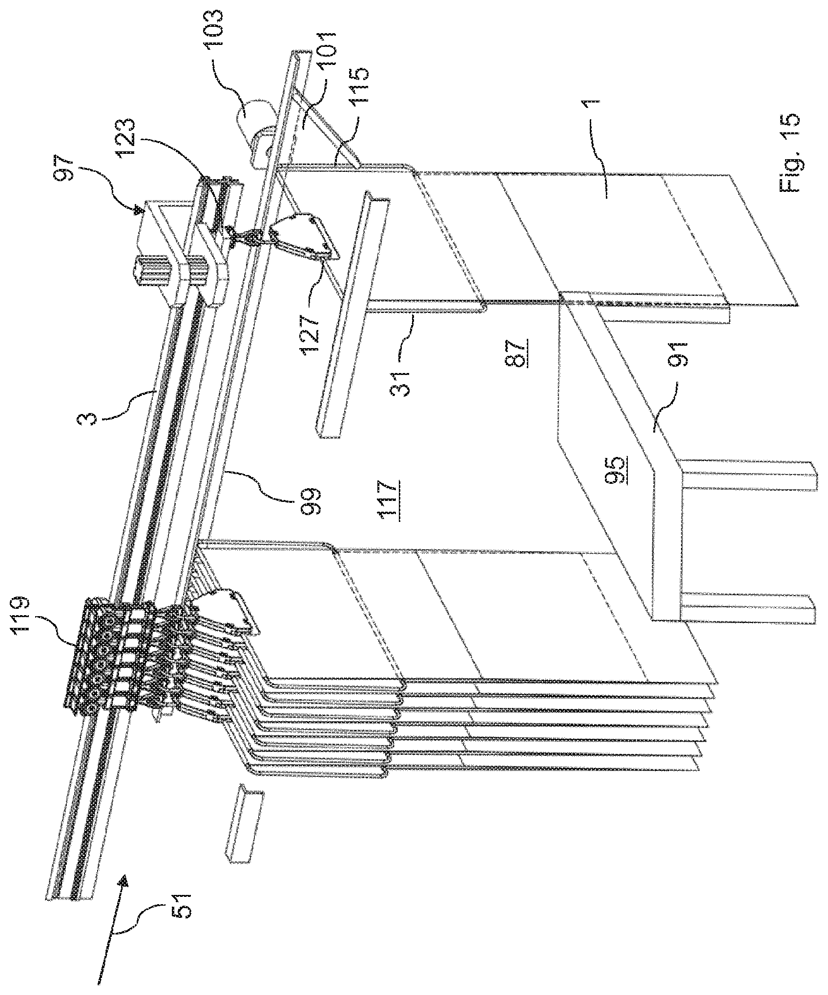
D00013

D00014

D00015

D00016

D00017

D00018

D00019

XML
uspto.report is an independent third-party trademark research tool that is not affiliated, endorsed, or sponsored by the United States Patent and Trademark Office (USPTO) or any other governmental organization. The information provided by uspto.report is based on publicly available data at the time of writing and is intended for informational purposes only.
While we strive to provide accurate and up-to-date information, we do not guarantee the accuracy, completeness, reliability, or suitability of the information displayed on this site. The use of this site is at your own risk. Any reliance you place on such information is therefore strictly at your own risk.
All official trademark data, including owner information, should be verified by visiting the official USPTO website at www.uspto.gov. This site is not intended to replace professional legal advice and should not be used as a substitute for consulting with a legal professional who is knowledgeable about trademark law.