Device For Collecting Split Wood
SCHUTT; Andreas
U.S. patent application number 16/585262 was filed with the patent office on 2020-01-23 for device for collecting split wood. The applicant listed for this patent is Andreas SCHUTT. Invention is credited to Andreas SCHUTT.
| Application Number | 20200023547 16/585262 |
| Document ID | / |
| Family ID | 61768324 |
| Filed Date | 2020-01-23 |


| United States Patent Application | 20200023547 |
| Kind Code | A1 |
| SCHUTT; Andreas | January 23, 2020 |
DEVICE FOR COLLECTING SPLIT WOOD
Abstract
A device for collecting split wood, having a plurality of bar elements, which each have a first and a second longitudinal portion, and a plurality of connecting elements, which connect the bar elements movably to one another. The second longitudinal portion of each bar element extends in a curved manner and the first longitudinal portion extends in a straight manner. The connecting elements cooperate with the second longitudinal portions, and a clamping element, which cooperates with the first longitudinal portions, is designed to firmly clamp the bar elements to a chopping block by their first longitudinal portions.
| Inventors: | SCHUTT; Andreas; (NEUHAUSEN, DE) | ||||||||||
| Applicant: |
|
||||||||||
|---|---|---|---|---|---|---|---|---|---|---|---|
| Family ID: | 61768324 | ||||||||||
| Appl. No.: | 16/585262 | ||||||||||
| Filed: | September 27, 2019 |
Related U.S. Patent Documents
| Application Number | Filing Date | Patent Number | ||
|---|---|---|---|---|
| PCT/EP2018/057491 | Mar 23, 2018 | |||
| 16585262 | ||||
| Current U.S. Class: | 1/1 |
| Current CPC Class: | B27L 7/08 20130101 |
| International Class: | B27L 7/08 20060101 B27L007/08 |
Foreign Application Data
| Date | Code | Application Number |
|---|---|---|
| Mar 29, 2017 | DE | 20 2017 101 806.7 |
Claims
1. A device for collecting split wood comprising: a plurality of bar elements, which each have a first and a second longitudinal portion, wherein the second longitudinal portion extends in a curved manner and the first longitudinal section extends in a straight manner, a plurality of connecting elements, which connect the bar elements movably to one another, wherein the connecting elements cooperate with the second longitudinal portions, and a clamping element, which cooperates with the first longitudinal portions and is designed to firmly clamp the bar elements to a chopping block by their first longitudinal portions.
2. The device as claimed in claim 1, wherein the bar elements are formed in an S shape.
3. The device as claimed in claim 1, wherein the second longitudinal portions form a collecting basket for the split wood with the connecting elements.
4. The device as claimed in claim 1, wherein the bar elements, in the fastened state on the chopping block, are evenly spaced in the circumferential direction of the chopping block, and further wherein a working region in the circumferential direction is left open.
5. The device as claimed in claim 1, wherein the connecting elements are formed as rope-shaped connecting elements.
6. The device as claimed in claim 5, wherein the connecting elements comprise wire ropes.
7. The device as claimed in claim 5, wherein the bar elements have bores in their second longitudinal portions for guiding through the rope-shaped connecting elements.
8. The device as claimed in claim 1, wherein the first longitudinal portions each have a receiving element for guiding through the clamping element.
9. The device as claimed in claim 1, wherein the clamping element is formed as a clamping belt.
10. The device as claimed in claim 1, wherein at least three bar elements are provided.
11. The device as claimed in claim 10, wherein five bar elements are provided.
12. The device as claimed in claim 1, wherein at least three connecting elements are provided.
13. The device as claimed in claim 12, wherein five connecting elements are provided.
14. The device as claimed in claim 1, wherein at least one stop element is provided on each of the first longitudinal portions of the bar elements, which stop element, in the fastened state on the chopping block, abuts against a working surface of the chopping block to prevent the respective bar element from slipping downwards.
15. The device as claimed in claim 1, wherein at least one bore for receiving a fastening element is provided in the first longitudinal portions of the bar elements.
16. The device as claimed in claim 1, wherein the connecting elements are detachable from the bar elements.
17. The device as claimed in claim 1, wherein the bar elements are formed with a T-shaped cross-section.
18. A device for collecting split wood comprising: a plurality of bar elements, which each have a first and a second longitudinal portion, wherein the second longitudinal portion extends in a curved manner and the first longitudinal section extends in a straight manner, a plurality of connecting elements, which connect the bar elements movably to one another, wherein the connecting elements cooperate with the second longitudinal portions, and a clamping element, which cooperates with the first longitudinal portions and is designed to firmly clamp the bar elements to a chopping block by their first longitudinal portions; wherein the bar elements are formed in an S shape such that the enclosed region is widened.
Description
CROSS-REFERENCE TO RELATED APPLICATIONS
[0001] This is a continuation application of International patent application PCT/EP2018/057491, filed on Mar. 23, 2018, which claims the priority of German patent application DE 20 2017 101 806.7, filed on Mar. 29, 2017. The entire contents of these priority applications are incorporated herein by reference.
BACKGROUND OF THE INVENTION
[0002] The present invention relates to a device for collecting split wood. When splitting wood, the log is conventionally placed on a so-called chopping block and then split with an ax. In this case, the two split pieces of wood usually fall off the side of the chopping block and onto the ground. The person chopping the wood then has to bend down to the wood to pick it up and move it away.
[0003] Bending down to the wood involves effort and is tiring.
SUMMARY OF THE INVENTION
[0004] Against this background, the object of the present invention is to provide a device which makes it easier to chop or split wood.
[0005] This object is achieved by a device for collecting split wood, which has the following features: [0006] a plurality of bar elements, which each have a first and a second longitudinal portion, wherein the second longitudinal portion extends in a curved manner and the first longitudinal section extends in a straight manner, [0007] a plurality of connecting elements, which connect the bar elements movably to one another, wherein the connecting elements cooperate with the second longitudinal portions, and [0008] a clamping element, which cooperates with the first longitudinal portions and is designed to firmly clamp the bar elements to a chopping block by their first longitudinal portions.
[0009] In other words, this means that the device provides a very flexibly useable collecting basket, which can be firmly clamped to the chopping block, conventionally a tree stump, in a very simple manner with the aid of the clamping element. In this case, the bar elements, in particular the second longitudinal portions of the bar elements, project upwards and form a type of collecting fence around the upper surface of the chopping block on which the wood to be split is placed.
[0010] This device prevents the split wood from falling off the side of the chopping block and onto the ground.
[0011] In a preferred further development, the bar elements are formed in an S shape. The second longitudinal portions further preferably form a collecting basket for the split wood with the connecting elements.
[0012] The curved S-shaped form of the bar elements enables a widening of the enclosed region so that the split wood can lie on the connecting elements. Therefore, the split wood does not fall back into the working region.
[0013] In a preferred further development, the bar elements--in the fastened state on the chopping block--are evenly spaced in the circumferential direction of the chopping block, wherein--in the circumferential direction--a working region is left open.
[0014] The working region consequently has an opening in the collecting basket so that the wood can be split in an unobstructed manner.
[0015] In a preferred further development, the connecting elements are formed as rope-shaped connecting elements, preferably as wire ropes.
[0016] By using wire ropes, the plurality of bar elements are movable relative to one another so that a very flexible arrangement on a chopping block is possible.
[0017] In a preferred further development, these bar elements have, in their second longitudinal portions, bores for guiding through the rope-shaped connecting elements. The first longitudinal portions further preferably each have a receiving element for guiding through the clamping element.
[0018] The connection of the connecting elements to the bar elements is therefore possible in a very simple manner. The connection of the clamping element to the bar elements is also possible in a very simple manner with the aid of the receiving element.
[0019] In a preferred further development, the clamping element is formed as a clamping belt.
[0020] Such a clamping belt is a standard component, which is very cost-effective and simple to handle.
[0021] In a preferred further development, at least two, preferably five, bar elements are provided. Further preferably, at least three, preferably five, connecting elements are provided.
[0022] In a preferred further development, at least one stop element is provided in each case on the first longitudinal portions of the bar elements, which stop element--in the fastened state on the chopping block--abuts against a working surface of the chopping block to prevent the respective bar element from slipping downwards.
[0023] At least one bore for receiving a fastening element is further preferably provided in the first longitudinal portions of the bar elements.
[0024] These measures enable very stable attachment to a chopping block.
[0025] In a preferred further development, the connecting elements are detachable from the bar elements.
[0026] These measures have the advantage that the connecting elements can be replaced at any time.
[0027] In a preferred further development, the bar elements are formed with a T-shaped cross-section.
[0028] This configuration has been shown to be particularly advantageous since the bar elements are thus very stable on the one hand and, on the other, provide space for bores through which the connecting elements and the clamping belt can be guided.
[0029] Of course, the features mentioned above and those still to be explained below can be used not only in the combination described in each case, but also in other combinations or alone, without deviating from the scope of the present invention.
BRIEF DESCRIPTION OF DRAWINGS
[0030] Further advantages and configurations of the invention are revealed in the description of the accompanying drawing, which shows:
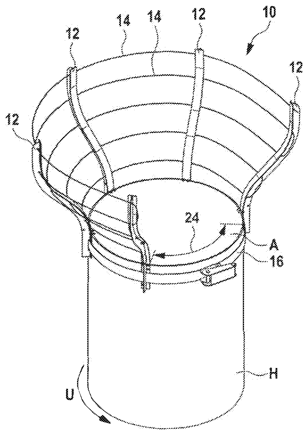
[0031] FIG. 1 a schematic illustration of an inventive device, which is attached to a chopping block;
[0032] FIG. 2 a side view of the inventive device shown in FIG. 1;
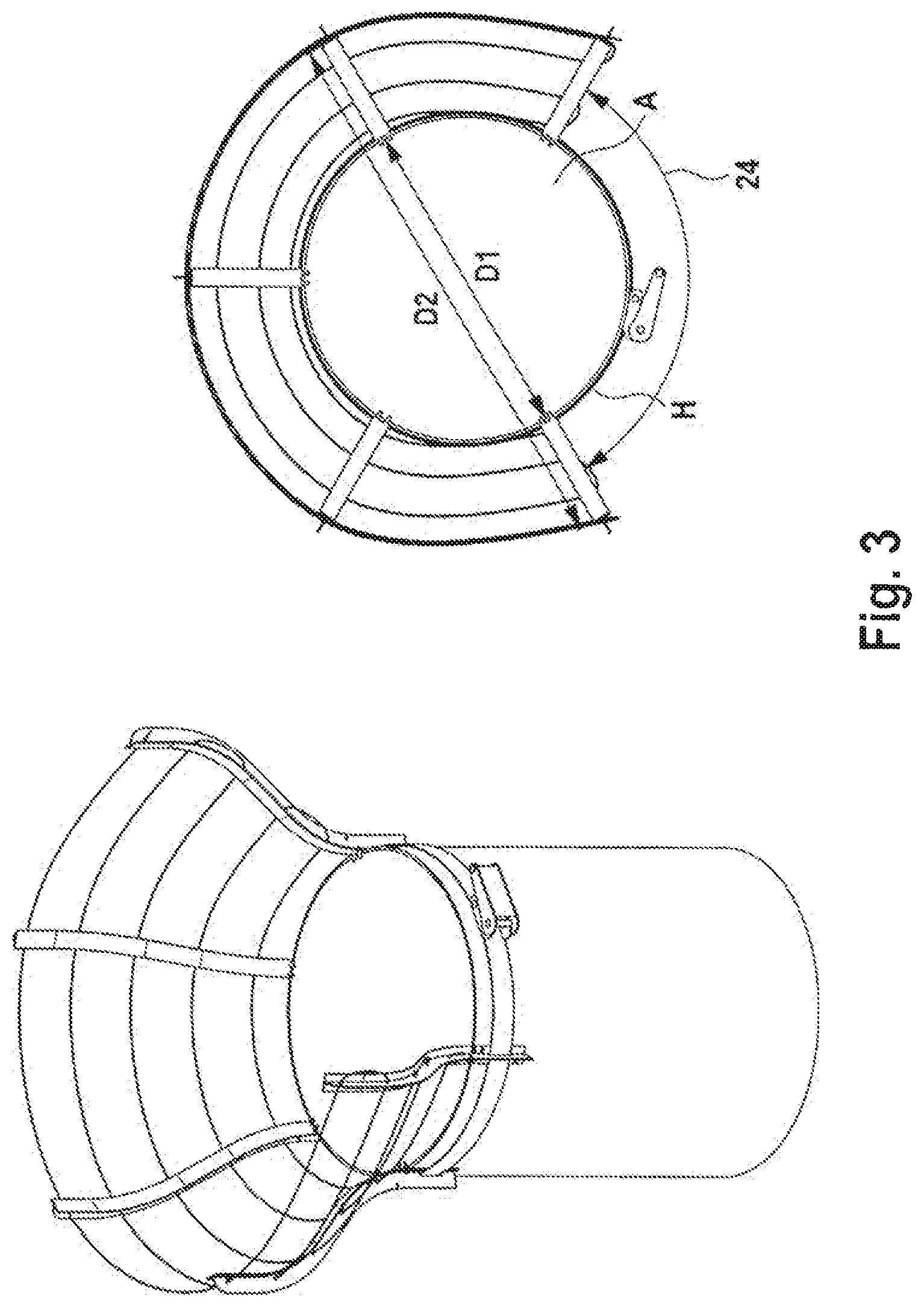
[0033] FIG. 3 a schematic plan view of the inventive device of FIG. 1; and
[0034] FIG. 4 a schematic detailed view of a region of the inventive device.
DETAILED DESCRIPTION OF THE PREFERRED EMBODIMENTS
[0035] In FIG. 1, a device for collecting split wood, simply referred to as a collecting device below, is illustrated schematically and denoted by the reference sign 10. The collecting device 10 comprises a plurality of bar-shaped elements 12--preferably five--a plurality of connecting elements 14--preferably five--and a clamping belt 16.
[0036] The bar elements 12 are formed to all be the same and, as illustrated in FIG. 2, have a first longitudinal portion L1 and a longitudinal portion L2 adjoining this. While the first longitudinal portion L1 extends linearly, i.e. straight, the second longitudinal portion L2 has a curved form so that the bar element as a whole has an approximately S-shaped form.
[0037] The bar elements 12 have--as seen in cross-section--a T shape, as revealed in particular in the view in FIG. 4. The respective bar element 12 consequently consists of a base 30 and a flange 32.
[0038] Bores 18, through which the connecting elements 14, preferably formed as wire ropes, can pass, are provided in the base 30 in the second longitudinal portion L2.
[0039] A rectangular opening, through which the clamping belt 16 can be guided, is provided in the base 30 in the first longitudinal portion L1.
[0040] As revealed in FIG. 4, stop elements 34 are provided on the flange 32 of a bar element 12 in the first longitudinal portion L1, which stop elements project from the flange 32 in the form of pins.
[0041] Bores 36, which serve for receiving fastening elements, for example nails, are moreover provided in the first longitudinal portion L1 of a bar element 12.
[0042] The collecting device 10 can be very easily attached to a chopping block H and clamped with the clamping belt 16. The stop elements 34 are provided to prevent the individual bar elements 12 from sitting too deep, for example, with respect to a working surface A of a chopping block H, which stop elements lie on the working surface A and therefore prevent the respective bar element from slipping downwards.
[0043] The bar elements can moreover be fastened on the chopping block H by inserting fastening elements, such as nails or screws, through the bores 36.
[0044] As revealed in FIGS. 1 and 3, the bar elements 12, with the connecting elements 14, surround a large region of the circumference of the chopping block H. However, a circumferential region 24 is left open, which serves as a working opening for chopping the wood.
[0045] As is again clearly revealed in FIG. 3, the collecting device opens upwards from a diameter D1, which corresponds to the diameter of the chopping block, to a considerably larger diameter D2. This larger diameter D2 is achieved by the S-shaped configuration of the bar elements.
[0046] The bar elements are preferably made from metal and preferably protected against rust. The connecting elements are likewise preferably manufactured from metal.
[0047] The collecting device 10 makes it easier to chop wood since the split wood does not fall to the ground from the chopping block and the working surface A thereof, but is instead collected by the fence-like connecting elements 14. The user then has to simply take the wood from the working surface and no longer has to bend to the ground.
[0048] All in all, the inventive device for collecting split wood provides a considerably more comfortable manner of working, while the simple construction means that it is cost-effective and can be used very flexibly.
* * * * *
D00000
D00001
D00002
D00003
XML
uspto.report is an independent third-party trademark research tool that is not affiliated, endorsed, or sponsored by the United States Patent and Trademark Office (USPTO) or any other governmental organization. The information provided by uspto.report is based on publicly available data at the time of writing and is intended for informational purposes only.
While we strive to provide accurate and up-to-date information, we do not guarantee the accuracy, completeness, reliability, or suitability of the information displayed on this site. The use of this site is at your own risk. Any reliance you place on such information is therefore strictly at your own risk.
All official trademark data, including owner information, should be verified by visiting the official USPTO website at www.uspto.gov. This site is not intended to replace professional legal advice and should not be used as a substitute for consulting with a legal professional who is knowledgeable about trademark law.