Polishing-pad Laminated Structure, Polishing-pad Positioning Instrument, And Method Of Attaching A Polishing Pad To A Polishing
Nomura; Toshikazu ; et al.
U.S. patent application number 16/426398 was filed with the patent office on 2020-01-23 for polishing-pad laminated structure, polishing-pad positioning instrument, and method of attaching a polishing pad to a polishing . The applicant listed for this patent is EBARA CORPORATION. Invention is credited to Masaki Kinoshita, Takashi Kishi, Toshikazu Nomura, Suguru Sakugawa, Nobuyuki Takahashi.
| Application Number | 20200023489 16/426398 |
| Document ID | / |
| Family ID | 69098134 |
| Filed Date | 2020-01-23 |
View All Diagrams
| United States Patent Application | 20200023489 |
| Kind Code | A1 |
| Nomura; Toshikazu ; et al. | January 23, 2020 |
POLISHING-PAD LAMINATED STRUCTURE, POLISHING-PAD POSITIONING INSTRUMENT, AND METHOD OF ATTACHING A POLISHING PAD TO A POLISHING TABLE
Abstract
A polishing-pad laminated structure which allows for easy alignment of a through-hole of a polishing pad with a sensor head installed in a polishing table is disclosed. The polishing-pad laminated structure includes a polishing pad and a release sheet. The polishing pad has a through-hole located at a position corresponding to a position of a sensor head disposed in the polishing table. The release sheet covers an adhesive surface of the polishing pad. The release sheet is divided into at least a first release sheet and a second release sheet. The first release sheet has a surface area smaller than a surface area of the second release sheet.
| Inventors: | Nomura; Toshikazu; (Tokyo, JP) ; Kinoshita; Masaki; (Tokyo, JP) ; Takahashi; Nobuyuki; (Tokyo, JP) ; Sakugawa; Suguru; (Tokyo, JP) ; Kishi; Takashi; (Tokyo, JP) | ||||||||||
| Applicant: |
|
||||||||||
|---|---|---|---|---|---|---|---|---|---|---|---|
| Family ID: | 69098134 | ||||||||||
| Appl. No.: | 16/426398 | ||||||||||
| Filed: | May 30, 2019 |
Related U.S. Patent Documents
| Application Number | Filing Date | Patent Number | ||
|---|---|---|---|---|
| 62691119 | Jun 28, 2018 | |||
| Current U.S. Class: | 1/1 |
| Current CPC Class: | B24B 37/26 20130101; B24B 37/005 20130101; B24B 47/22 20130101; B24B 37/345 20130101 |
| International Class: | B24B 47/22 20060101 B24B047/22; B24B 37/26 20060101 B24B037/26; B24B 37/34 20060101 B24B037/34; B24B 37/005 20060101 B24B037/005 |
Claims
1. A polishing-pad laminated structure comprising: a polishing pad having a through-hole located at a position corresponding to a position of a sensor head disposed in a polishing table; and a release sheet covering an adhesive surface of the polishing pad, the release sheet being divided into at least a first release sheet and a second release sheet, the first release sheet having a surface area smaller than a surface area of the second release sheet.
2. The polishing-pad laminated structure according to claim 1, wherein the second release sheet has a through-hole at a same position as a position of the through-hole of the polishing pad.
3. The polishing-pad laminated structure according to claim 1, further comprising: a release assisting projection connected to an edge of the second release sheet.
4. A polishing-pad positioning instrument for positioning a polishing pad with respect to a polishing table, comprising: a positioning structure configured to be removably attached to the polishing table, the positioning structure including (i) a first positioning protrusion configured to be inserted into a table hole formed in a pad support surface of the polishing table, and (ii) a second positioning protrusion fixed to the first positioning protrusion, the second positioning protrusion having a cross-sectional shape corresponding to a cross-sectional shape of a through-hole formed in the polishing pad.
5. The polishing-pad positioning instrument according to claim 4, wherein a length of the second positioning protrusion along a central axis of the second positioning protrusion is not less than a thickness of the polishing pad.
6. The polishing-pad positioning instrument according to claim 4, further comprising a third positioning protrusion connected to the second positioning protrusion, the third positioning protrusion having a mark indicating a position of the first positioning protrusion with respect to the central axis of the second positioning protrusion.
7. The polishing-pad positioning instrument according to claim 6, further comprising a support structure supporting the third positioning protrusion, the support structure having at least two legs separated from each other.
8. The polishing-pad positioning instrument according to claim 7, wherein the first positioning protrusion and the second positioning protrusion are located between the at least two legs.
9. The polishing-pad positioning instrument according to claim 7, wherein: the support structure includes a stopper having an engagement portion configured to be inserted into a recessed portion of the third positioning protrusion; and a distance from bottom surfaces of the legs to a top surface of the engagement portion is longer than a distance from a tip end of the first positioning protrusion to an upper surface of the recessed portion.
10. The polishing-pad positioning instrument according to claim 4, further comprising a support structure supporting the second positioning protrusion, the support structure having a bottom surface perpendicular to a central axis of the second positioning protrusion.
11. The polishing-pad positioning instrument according to claim 10, wherein the second positioning protrusion is supported by the support structure such that the second positioning protrusion is movable along the central axis of the second positioning protrusion.
12. The polishing-pad positioning instrument according to claim 11, further comprising a spring disposed between the second positioning protrusion and the support structure, the positioning structure being forced by the spring in an extending direction of the central axis of the second positioning protrusion.
13. A method of attaching a polishing pad to a pad support surface of a polishing table, comprising: (i) providing a polishing-pad laminated structure including the polishing pad and a release sheet, the polishing pad having a through-hole located at a position corresponding to a position of a sensor head disposed in the polishing table, the release sheet covering an adhesive surface of the polishing pad, the release sheet being divided into at least a first release sheet and a second release sheet, the first release sheet having a surface area smaller than a surface area of the second release sheet; (ii) providing a positioning structure including a first positioning protrusion and a second positioning protrusion, the first positioning protrusion being configured to be inserted into a table hole formed in the pad support surface of the polishing table, the second positioning protrusion being fixed to the first positioning protrusion, the second positioning protrusion having a cross-sectional shape corresponding to a cross-sectional shape of the through-hole of the polishing pad; (iii) placing the polishing-pad laminated structure, from which the first release sheet has been removed, on the pad support surface of the polishing table; (iv) inserting the first positioning protrusion into the table hole through the through-hole of the polishing pad; (v) inserting the second positioning protrusion into the through-hole of the polishing pad; (vi) removing the positioning structure from the polishing table and the polishing pad; and (vii) removing the second release sheet from the polishing pad and attaching the entire adhesive surface of the polishing pad to the pad support surface of the polishing table.
14. A method of attaching a polishing pad to a pad support surface of a polishing table, comprising: (i) providing a polishing-pad laminated structure including the polishing pad and a release sheet, the polishing pad having a through-hole located at a position corresponding to a position of a sensor head disposed in the polishing table, the release sheet covering an adhesive surface of the polishing pad, the release sheet being divided into at least a first release sheet and a second release sheet, the first release sheet having a surface area smaller than a surface area of the second release sheet; (ii) providing a positioning structure including a first positioning protrusion and a second positioning protrusion, the first positioning protrusion being configured to be inserted into a table hole formed in the pad support surface of the polishing table, the second positioning protrusion being fixed to the first positioning protrusion, the second positioning protrusion having a cross-sectional shape corresponding to a cross-sectional shape of the through-hole of the polishing pad; (iii) inserting the first positioning protrusion into the table hole; (iv) placing the polishing-pad laminated structure, from which the first release sheet has been removed, on the pad support surface of the polishing table; (v) inserting the second positioning protrusion into the through-hole of the polishing pad; (vi) removing the positioning structure from the polishing table and the polishing pad; and (vii) removing the second release sheet from the polishing pad and attaching the entire adhesive surface of the polishing pad to the pad support surface of the polishing table.
Description
CROSS REFERENCE TO RELATED APPLICATION
[0001] This document claims priority to U.S. Provisional Patent Application No. 62/691,119 filed Jun. 28, 2018, the entire contents of which are hereby incorporated by reference.
BACKGROUND
[0002] Manufacturing processes of semiconductor devices include a process of polishing a dielectric film, e.g., SiO.sub.2, and a process of polishing a metal film, e.g., copper or tungsten. Manufacturing processes of backside illumination CMOS sensor and through-silicon via (TSV) include a process of polishing a silicon layer (silicon wafer), in addition to the polishing processes of the dielectric film and the metal film.
[0003] Wafer polishing is generally performed using a chemical mechanical polishing apparatus (or a CMP apparatus). This CMP apparatus is configured to polish a surface of the wafer by bringing the wafer into sliding contact with a polishing pad attached to a polishing table while supplying slurry onto the polishing pad. The polishing of the wafer is terminated when a thickness of a film (an insulating film, a metal film, a silicon layer, etc.), constituting the surface of the wafer, reaches a predetermined target value. Therefore, the film thickness is measured during polishing of the wafer.
[0004] An optical film-thickness measuring device is one example of a film-thickness measuring device. The optical film-thickness measuring device is configured to direct light to a surface of a wafer and analyze optical information contained in reflected light from the wafer to thereby measure a film thickness. The optical film-thickness measuring device includes a sensor head including a light emitter and a light receiver disposed in the polishing table. The polishing pad has a through-hole at the same position as the position of the sensor head. The light emitted from the sensor head is directed to the wafer through the through-hole of the polishing pad, and the reflected light from the wafer passes through the through-hole again to reach the sensor head.
[0005] The polishing pad wears gradually as polishing of wafers and dressing of the polishing pad are repeated. Therefore, if the wear of the polishing pad has progressed to some extent, it is replaced with a new polishing pad. A back surface of the polishing pad is composed of an adhesive surface, and the polishing pad is attached to the top surface of the polishing table. When attaching the polishing pad to the polishing table, it is important to accurately align the through-hole of the polishing pad with the sensor head disposed in the polishing table. This is because, if the through-hole of the polishing pad is not in alignment with the sensor head, the film-thickness measuring accuracy is lowered.
[0006] However, it is difficult to accurately align the through-hole of the polishing pad with the sensor head disposed in the polishing table. In particular, since the through-hole of the polishing pad are typically small, it takes a long time to properly attach the polishing pad to the polishing table, thus resulting in a decrease in operation rate of the polishing apparatus.
SUMMARY OF THE INVENTION
[0007] Therefore, according to one embodiment, there are provided a polishing-pad laminated structure and a polishing-pad positioning instrument which allow for easy alignment of a through-hole of a polishing pad with a sensor head installed in a polishing table. Further, according to one embodiment, there is provided a method of attaching a polishing pad to a polishing table using the polishing-pad positioning instrument.
[0008] The below-described embodiments relate to a polishing pad used in a polishing apparatus for polishing a substrate such as a wafer, and in particular, a polishing pad used in a polishing apparatus provided with a polishing table in which a film-thickness measuring device is disposed.
[0009] In an embodiment, there is provided a polishing-pad laminated structure comprising: a polishing pad having a through-hole located at a position corresponding to a position of a sensor head disposed in a polishing table; and a release sheet covering an adhesive surface of the polishing pad, the release sheet being divided into at least a first release sheet and a second release sheet, the first release sheet having a surface area smaller than a surface area of the second release sheet.
[0010] In an embodiment, the second release sheet has a through-hole at a same position as a position of the through-hole of the polishing pad.
[0011] In an embodiment, the polishing-pad laminated structure further comprises a release assisting projection connected to an edge of the second release sheet.
[0012] In an embodiment, there is provided a polishing-pad positioning instrument for positioning a polishing pad with respect to a polishing table, comprising: a positioning structure configured to be removably attached to the polishing table, the positioning structure including (i) a first positioning protrusion configured to be inserted into a table hole formed in a pad support surface of the polishing table, and (ii) a second positioning protrusion fixed to the first positioning protrusion, the second positioning protrusion having a cross-sectional shape corresponding to a cross-sectional shape of a through-hole formed in the polishing pad.
[0013] In an embodiment, a length of the second positioning protrusion along a central axis of the second positioning protrusion is not less than a thickness of the polishing pad.
[0014] In an embodiment, the polishing-pad positioning instrument further comprises a third positioning protrusion connected to the second positioning protrusion, the third positioning protrusion having a mark indicating a position of the first positioning protrusion with respect to the central axis of the second positioning protrusion.
[0015] In an embodiment, the polishing-pad positioning instrument further comprises a support structure supporting the third positioning protrusion, the support structure having at least two legs separated from each other.
[0016] In an embodiment, the first positioning protrusion and the second positioning protrusion are located between the at least two legs.
[0017] In an embodiment, the support structure includes a stopper having an engagement portion configured to be inserted into a recessed portion of the third positioning protrusion, and a distance from bottom surfaces of the legs to a top surface of the engagement portion is longer than a distance from a tip end of the first positioning protrusion to an upper surface of the recessed portion.
[0018] In an embodiment, the polishing-pad positioning instrument further comprises a support structure supporting the second positioning protrusion, the support structure having a bottom surface perpendicular to a central axis of the second positioning protrusion.
[0019] In an embodiment, the second positioning protrusion is supported by the support structure such that the second positioning protrusion is movable along the central axis of the second positioning protrusion.
[0020] In an embodiment, the polishing-pad positioning instrument further comprises a spring disposed between the second positioning protrusion and the support structure, the positioning structure being forced by the spring in an extending direction of the central axis of the second positioning protrusion.
[0021] In an embodiment, there is provided a method of attaching a polishing pad to a pad support surface of a polishing table, comprising: (i) providing a polishing-pad laminated structure including the polishing pad and a release sheet, the polishing pad having a through-hole located at a position corresponding to a position of a sensor head disposed in the polishing table, the release sheet covering an adhesive surface of the polishing pad, the release sheet being divided into at least a first release sheet and a second release sheet, the first release sheet having a surface area smaller than a surface area of the second release sheet; (ii) providing a positioning structure including a first positioning protrusion and a second positioning protrusion, the first positioning protrusion being configured to be inserted into a table hole formed in the pad support surface of the polishing table, the second positioning protrusion being fixed to the first positioning protrusion, the second positioning protrusion having a cross-sectional shape corresponding to a cross-sectional shape of the through-hole of the polishing pad; (iii) placing the polishing-pad laminated structure, from which the first release sheet has been removed, on the pad support surface of the polishing table; (iv) inserting the first positioning protrusion into the table hole through the through-hole of the polishing pad; (v) inserting the second positioning protrusion into the through-hole of the polishing pad; (vi) removing the positioning structure from the polishing table and the polishing pad; and (vii) removing the second release sheet from the polishing pad and attaching the entire adhesive surface of the polishing pad to the pad support surface of the polishing table.
[0022] In an embodiment, there is provided a method of attaching a polishing pad to a pad support surface of a polishing table, comprising: (i) providing a polishing-pad laminated structure including the polishing pad and a release sheet, the polishing pad having a through-hole located at a position corresponding to a position of a sensor head disposed in the polishing table, the release sheet covering an adhesive surface of the polishing pad, the release sheet being divided into at least a first release sheet and a second release sheet, the first release sheet having a surface area smaller than a surface area of the second release sheet; (ii) providing a positioning structure including a first positioning protrusion and a second positioning protrusion, the first positioning protrusion being configured to be inserted into a table hole formed in the pad support surface of the polishing table, the second positioning protrusion being fixed to the first positioning protrusion, the second positioning protrusion having a cross-sectional shape corresponding to a cross-sectional shape of the through-hole of the polishing pad; (iii) inserting the first positioning protrusion into the table hole; (iv) placing the polishing-pad laminated structure, from which the first release sheet has been removed, on the pad support surface of the polishing table; (v) inserting the second positioning protrusion into the through-hole of the polishing pad; (vi) removing the positioning structure from the polishing table and the polishing pad; and (vii) removing the second release sheet from the polishing pad and attaching the entire adhesive surface of the polishing pad to the pad support surface of the polishing table.
[0023] According to the embodiments described above, the position of the polishing pad with respect to the polishing table is adjusted in a state where the first release sheet having a small surface area has been removed. Since the polishing-pad laminated structure can be moved relatively freely on the polishing table, the through-hole of the polishing pad can be precisely aligned with the sensor head disposed in the polishing table. Further, immediately after the alignment of the through-hole of the polishing pad with the sensor head is completed, the exposed portion of the adhesive surface of the polishing pad (i.e., the portion that has been covered with the first release sheet) is pressed against the polishing table, so that the relative position of the polishing pad with respect to the polishing table can be fixed.
[0024] Furthermore, according to the above-described embodiments, the positioning of the polishing pad with respect to the polishing table is completed by inserting the second positioning protrusion of the positioning structure into the through-hole of the polishing pad. Accordingly, the attachment work of the polishing pad can be easy.
BRIEF DESCRIPTION OF THE DRAWINGS
[0025] FIG. 1 is a view showing an embodiment of a polishing apparatus;
[0026] FIG. 2 is a schematic cross-sectional view showing the polishing apparatus including an optical film-thickness measuring device;
[0027] FIG. 3 is a top view of a through-hole of a polishing pad shown in FIG. 2;
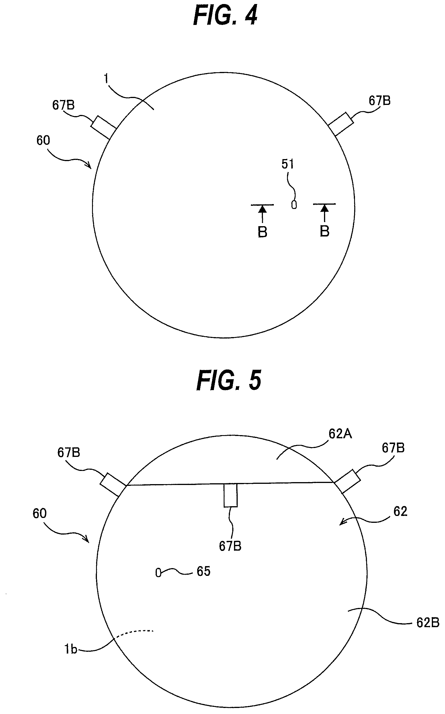
[0028] FIG. 4 is a top view showing a polishing-pad laminated structure having a new polishing pad;
[0029] FIG. 5 is a backside view of the polishing-pad laminated structure shown in FIG. 4;
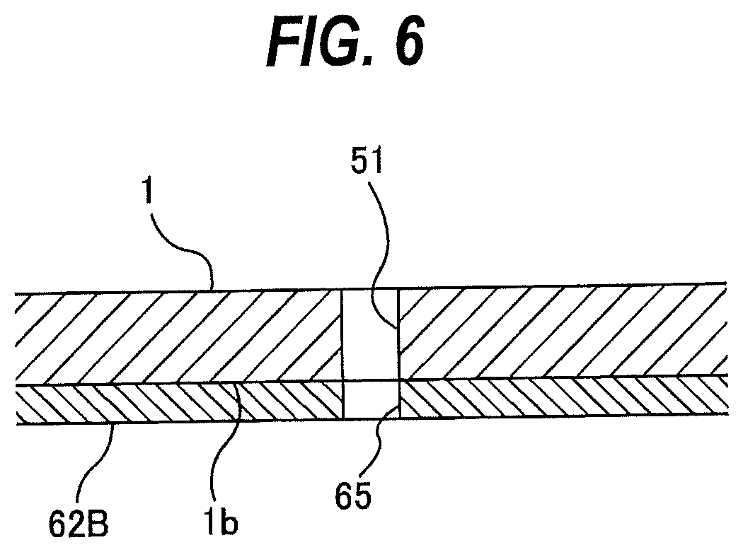
[0030] FIG. 6 is a cross-sectional view taken along a line B-B in FIG. 4;
[0031] FIG. 7 is a flow chart for explaining an attaching operation of a polishing pad to a polishing table;
[0032] FIG. 8A is a side view of a positioning structure used to position the polishing pad with respect to the polishing table;
[0033] FIG. 8B is a bottom view of the positioning structure shown in FIG. 8A;
[0034] FIG. 9 is a cross-sectional view showing the positioning structure in a state in which a first positioning protrusion is inserted into a drain hole of the polishing table;
[0035] FIG. 10 is a diagram showing a process of attaching the polishing pad to the polishing table using the positioning structure;
[0036] FIGS. 11A and 11B are diagrams each illustrating a process of attaching the polishing pad to the polishing table using the positioning structure;
[0037] FIG. 12 is a perspective view showing another embodiment of the polishing-pad positioning instrument;
[0038] FIG. 13 is a front view of the polishing-pad positioning instrument shown in FIG. 12;
[0039] FIG. 14 is a cross-sectional view taken along a line C-C of FIG. 13;
[0040] FIG. 15 is a view showing a process of attaching a polishing pad to a polishing table using the polishing-pad positioning instrument;
[0041] FIGS. 16A and 16B are diagrams each showing a process of attaching the polishing pad to the polishing table using the polishing-pad positioning instrument;
[0042] FIG. 17 is a cross-sectional view showing a positional relationship among the positioning structure, the polishing-pad laminated structure, and the polishing table;
[0043] FIGS. 18A and 18B are perspective views each showing still another embodiment of the polishing-pad positioning instrument;
[0044] FIGS. 19A and 19B are diagrams each showing a process of attaching a polishing pad to a polishing table using the polishing-pad positioning instrument;
[0045] FIG. 20 is a view showing a process of attaching the polishing pad to the polishing table using the polishing-pad positioning instrument;
[0046] FIG. 21 is a cross-sectional view showing a positional relationship among the positioning structure, the polishing-pad laminated structure, and the polishing table;
[0047] FIG. 22 is a view showing a process of attaching the polishing pad to the polishing table using the polishing-pad positioning instrument;
[0048] FIG. 23 is a view showing a process of attaching the polishing pad to the polishing table using the polishing-pad positioning instrument;
[0049] FIG. 24 is a view showing a process of attaching the polishing pad to the polishing table using the polishing-pad positioning instrument;
[0050] FIG. 25 is a cross-sectional view showing a positional relationship among the positioning structure, the polishing-pad laminated structure, and the polishing table;
[0051] FIG. 26A is a top view showing another embodiment of a polishing-pad laminated structure, and FIG. 26B is a backside view of the polishing-pad laminated structure shown in FIG. 26A;
[0052] FIG. 27A is a top view showing still another embodiment of a polishing-pad laminated structure, and FIG. 27B is a backside view of the polishing-pad laminated structure shown in FIG. 27A;
[0053] FIG. 28 is a schematic cross-sectional view showing an embodiment of a polishing apparatus having a polishing table in which a plurality of sensor heads are arranged;
[0054] FIG. 29A is a top view showing an embodiment of a polishing-pad laminated structure used for the polishing table in which two sensor heads are arranged, and FIG. 29B is a backside view of the polishing-pad laminated structure shown in FIG. 29A;
[0055] FIG. 30 is a perspective view showing an embodiment of a polishing-pad positioning instrument suitable for the polishing-pad laminated structure shown in FIGS. 29A and 29B;
[0056] FIG. 31 is a front view of the polishing-pad positioning instrument shown in FIG. 30;
[0057] FIG. 32 is a cross-sectional view taken along a line D-D of FIG. 31;
[0058] FIGS. 33A and 33B are perspective views each showing another embodiment of a polishing-pad positioning instrument suitable for the polishing-pad laminated structure shown in FIGS. 29A and 29B;
[0059] FIG. 34 is a perspective view showing another embodiment of a polishing-pad positioning instrument suitable for the polishing-pad laminated structure shown in FIGS. 29A and 29B;
[0060] FIG. 35 is a front view of the polishing-pad positioning instrument shown in FIG. 34;
[0061] FIGS. 36A and 36B are diagrams each showing a process of attaching a polishing pad to a polishing table using the polishing-pad positioning instrument;
[0062] FIG. 37 is a view showing a process of attaching the polishing pad to the polishing table using the polishing-pad positioning instrument;
[0063] FIG. 38 is a view showing a process of attaching the polishing pad to the polishing table using the polishing-pad positioning instrument;
[0064] FIG. 39A is a top view showing another embodiment of a polishing-pad laminated structure used for a polishing table in which two sensor heads are arranged, and FIG. 39B is a backside view of the polishing-pad laminated structure shown in FIG. 39A;
[0065] FIG. 40A is a top view showing still another embodiment of a polishing-pad laminated structure used for a polishing table in which two sensor heads are arranged, and FIG. 40B is a backside view of the polishing-pad laminated structure shown in FIG. 40A;
[0066] FIG. 41A is a top view showing an embodiment of a polishing-pad laminated structure used for a polishing table in which three sensor heads are arranged, and FIG. 41B is a backside view of the polishing-pad laminated structure shown in FIG. 41A;
[0067] FIG. 42A is a top view showing another embodiment of a polishing-pad laminated structure used for a polishing table in which three sensor heads are arranged, and FIG. 42B is a backside view of the polishing-pad laminated structure shown in FIG. 42A;
[0068] FIG. 43A is a top view showing still another embodiment of a polishing-pad laminated structure used for a polishing table in which three sensor heads are arranged, and FIG. 43B is a backside view of the polishing-pad laminated structure shown in FIG. 43A;
[0069] FIG. 44A is a perspective view of another embodiment of a positioning structure;
[0070] FIG. 44B is a side view of the positioning structure shown in FIG. 44A;
[0071] FIG. 44C is a bottom view of the positioning structure shown in FIG. 44A;
[0072] FIG. 45 is a perspective view of one embodiment of a support structure for supporting the positioning structure shown in FIGS. 44A to 44C;
[0073] FIG. 46 is a view of the positioning structure and the support structure shown in FIG. 45 as viewed from obliquely below;
[0074] FIG. 47 is a sectional view taken along a line E-E of FIG. 45;
[0075] FIG. 48 is a view showing a state in which an engagement portion of a stopper is disengaged from a recessed portion of a third positioning protrusion;
[0076] FIG. 49 is a diagram showing a process of peeling a first release sheet from the polishing-pad laminated structure;
[0077] FIG. 50 is a view showing a state in which the polishing-pad laminated structure from which the first release sheet has been peeled is placed on a pad support surface of the polishing table;
[0078] FIGS. 51A and 51B are views each showing a process of inserting a first positioning protrusion of a positioning structure into a drain hole of a polishing table through a through-hole of a polishing pad;
[0079] FIG. 52 is a view showing a state in which the first positioning protrusion of the positioning structure is inserted into the drain hole of the polishing table and a second positioning protrusion is inserted into the through-hole of the polishing pad;
[0080] FIGS. 53A and 53B are diagrams each showing a process of inserting a third positioning protrusion of the positioning structure, which is standing by itself on the polishing table, into a vertical hole of the support structure;
[0081] FIGS. 54A and 54B are diagrams each showing a process of inserting a first positioning protrusion of another positioning structure into another drain hole of the polishing table through a through-hole of the polishing pad;
[0082] FIGS. 55A and 55B are diagrams each showing a process of inserting the third positioning protrusion of the positioning structure, which is standing by itself on the polishing table, into a vertical hole of another support structure;
[0083] FIG. 56 is a view showing a process of peeling a second release sheet and a third release sheet from the polishing pad, and attaching the entire adhesive surface of the polishing pad to the pad support surface of the polishing table;
[0084] FIG. 57A is a perspective view of another embodiment of a positioning structure;
[0085] FIG. 57B is a side view of the positioning structure shown in FIG. 57A;
[0086] FIG. 57C is a bottom view of the positioning structure shown in FIG. 57A;
[0087] FIG. 58 is a perspective view of one embodiment of a support structure for supporting positioning structures, one of which is shown in FIGS. 57A to 57C;
[0088] FIG. 59 is a view of the positioning structures and the support structure shown in FIG. 58 as viewed obliquely from below;
[0089] FIG. 60 is a cross-sectional view of the support structure and the positioning structure shown in FIG. 58;
[0090] FIG. 61 is a view showing a state in which an engagement portion of a stopper is disengaged from a recessed portion of a third positioning protrusion;
[0091] FIG. 62 is a view showing a state in which a polishing-pad positioning instrument is placed on a polishing pad with the stoppers engaging with the third positioning protrusions;
[0092] FIG. 63 is a view showing a state in which the engagement portions of the stoppers are disengaged from the recessed portions of the third positioning protrusions;
[0093] FIG. 64 is a view showing a state in which a first positioning protrusion is inserted into the drain hole (table hole) of the polishing table, and a second positioning protrusion is inserted into the through-hole of the polishing pad;
[0094] FIG. 65 is a perspective view showing another embodiment of a support structure for supporting the positioning structure shown in FIGS. 57A to 57C;
[0095] FIG. 66 is a view of the positioning structure and the support structure shown in FIG. 65 as viewed obliquely from below;
[0096] FIG. 67 is a cross-sectional view taken along a line F-F of FIG. 65;
[0097] FIG. 68 is a view showing a state in which the engagement portion of the stopper is disengaged from the recessed portion of the third positioning protrusion;
[0098] FIG. 69 is a view showing a state in which two polishing-pad positioning instruments are placed on a polishing pad with the stoppers engaging with the third positioning protrusions;
[0099] FIG. 70 is a view showing a state in which the engagement portions of the stoppers are disengaged from the recessed portions of the third positioning protrusions; and
[0100] FIG. 71 is a view showing another embodiment of a positioning structure.
DESCRIPTION OF EMBODIMENTS
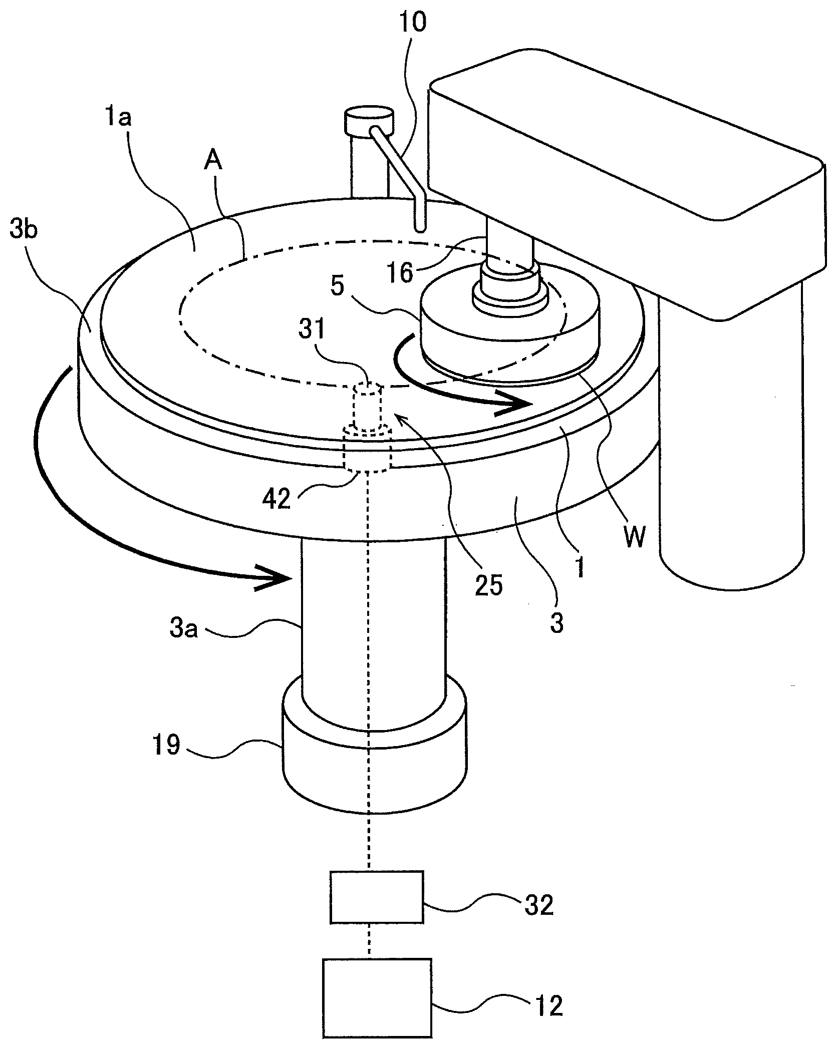
[0101] Embodiments will be described below with reference to the drawings. FIG. 1 is a view showing an embodiment of a polishing apparatus. As shown in FIG. 1, the polishing apparatus includes a polishing table 3 to which a polishing pad 1 having a polishing surface 1a is attached, a polishing head 5 for holding a wafer W, which is an example of a substrate, and pressing the wafer W against the polishing pad 1 on the polishing table 3 to polish the wafer W, a polishing-liquid supply nozzle 10 for supplying a polishing liquid (e.g., slurry) onto the polishing pad 1, and a polishing controller 12 for controlling polishing of the wafer W.
[0102] The polishing table 3 is coupled to a table motor 19 through a table shaft 3a, so that the polishing table 3 is rotated by the table motor 19 in a direction indicated by arrow. The table motor 19 is located below the polishing table 3. The polishing pad 1 is attached to a pad support surface 3b of the polishing table 3. The pad support surface 3b is composed of an upper surface of the polishing table 3. The polishing pad 1 has an upper surface, which provides a polishing surface 1a for polishing the wafer W. The polishing head 5 is secured to a lower end of a polishing head shaft 16. The polishing head 5 is configured to be able to hold the wafer W on its lower surface by vacuum suction. The polishing head shaft 16 can be elevated and lowered by an elevating mechanism (not shown in the drawing).
[0103] Polishing of the wafer W is performed as follows. The polishing head 5 and the polishing table 3 are rotated in directions indicated by arrows, while the polishing liquid (or slurry) is supplied from the polishing-liquid supply nozzle 10 onto the polishing pad 1. In this state, the polishing head 5 presses the wafer W against the polishing surface 1a of the polishing pad 1. The surface of the wafer W is polished by a mechanical action of abrasive grains contained in the polishing liquid and a chemical action of the polishing liquid.
[0104] The polishing apparatus includes an optical film-thickness measuring device (film-thickness measuring apparatus) 25 for measuring a film thickness of the wafer W. This optical film-thickness measuring device 25 has a sensor module 42 for obtaining an optical signal that varies in accordance with the film thickness of the wafer W, and a processor 32 for determining the film thickness from the optical signal. The sensor module 42 is disposed in the polishing table 3, and the processor 32 is coupled to the polishing controller 12. The sensor module 42 includes a sensor head 31 configured to direct light to the surface of the wafer W and receive reflected light from the wafer W. The sensor head 31 rotates together with the polishing table 3 as indicated by arrow A, and obtains the optical signal of the wafer W held on the polishing head 5. The sensor module 42 is coupled to the processor 32 so that the optical signal, obtained by the sensor module 42, is sent to the processor 32.
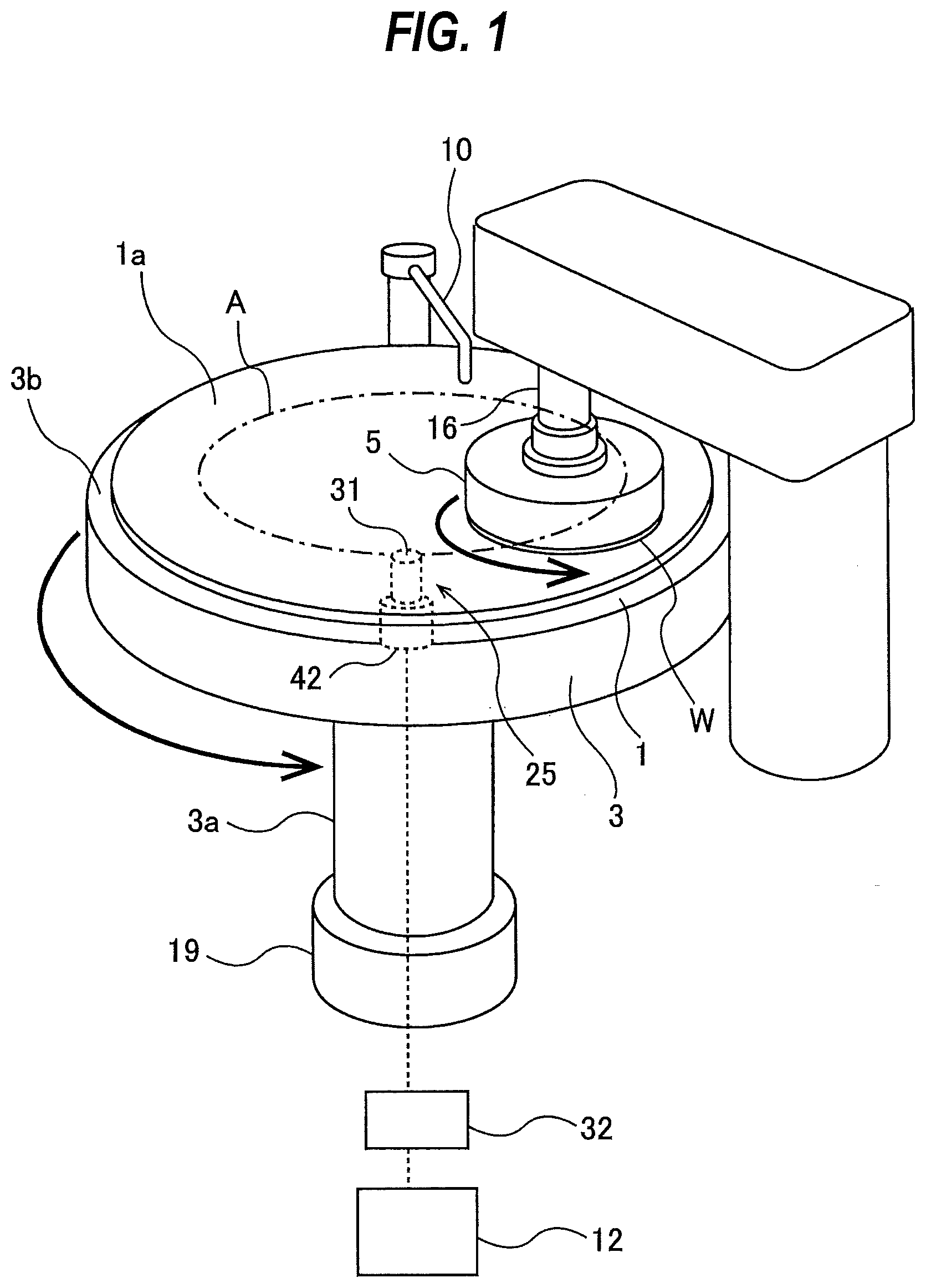
[0105] FIG. 2 is a schematic cross-sectional view showing the polishing apparatus having the optical film-thickness measuring device 25. The polishing head shaft 16 is coupled to a polishing head motor 18 through a coupling device 17, such as belt, so that the polishing head shaft 16 is rotated by the polishing head motor 18. This rotation of the polishing head shaft 16 is transmitted to the polishing head 5 to rotate the polishing head 5 in the direction indicated by the arrow.
[0106] As described previously, the optical film-thickness measuring device 25 includes the sensor module 42 having the sensor head 31 and the processor 32. The sensor module 42 includes an optical device 47 having at least a light source and a spectrometer, and optical fibers 48 coupled to the optical device 47. The tip ends of the optical fibers 48 constitute the sensor head 31, and the other ends of the optical fibers 48 are coupled to the optical device 47. The optical device 47 is configured to emit light, which travels through the optical fibers 48 and is directed from the sensor head 31 to the surface, to be polished, of the wafer W. Reflected light from the wafer W is received by the sensor head 31 and is further transmitted to the optical device 47 through the optical fibers 48. The optical device 47 is configured to resolve the reflected light according to wavelength and measure intensity of the reflected light over a predetermined wavelength range.
[0107] The polishing table 3 has a sensor hole 50A and a drain hole 50B formed in the upper surface of the polishing table 3. The drain hole 50B functions as a table hole used in positioning of the polishing pad 1 with respect to the polishing table 3 as described later. The polishing pad 1 has a through-hole 51 at a position corresponding to the holes 50A and 50B. The holes 50A, 50B are in communication with the through-hole 51, and the through-hole 51 is located right above the holes 50A, 50B. The through-hole 51 has an upper open end lying in the polishing surface 1a. The sensor hole 50A is coupled to a liquid supply passage 53. This liquid supply passage 53 is coupled to a liquid supply source 55 via a rotary join (not shown). The drain hole 50B is coupled to a liquid discharge passage 54.
[0108] The sensor head 31, which is constituted by the tip ends of the optical fibers 48, is located in the sensor hole 50A, and is located close to the surface, to be polished, of the wafer W. The sensor head 31 is located so as to sweep across the surface, to be polished, of the wafer W held by the polishing head 5. Each time the polishing table 3 rotates, the light is directed to a plurality of areas of the wafer W.
[0109] During polishing of the wafer W, the liquid supply source 55 supplies water (preferably pure water) as a transparent liquid into the sensor hole 50A through the liquid supply passage 53. The water fills a space formed between the lower surface of the wafer W and the sensor head 31. The water further flows into the drain hole 50B and is expelled therefrom through the liquid discharge passage 54. The polishing liquid is discharged together with the water and thus a path of light is ensured. The liquid supply passage 53 is provided with a valve (not shown in the drawing) configured to operate in conjunction with the rotation of the polishing table 3. The valve operates so as to stop the flow of the water or reduce the flow of the water when the wafer W is not located over the through-hole 51.
[0110] During polishing of the wafer W, the sensor head 31 directs the light to the wafer W, and the sensor head 31 receives the reflected light from the wafer W. The optical device 47 measures the intensity of the reflected light at each of the wavelengths over a predetermined wavelength range, and transmits light intensity data obtained to the processor 32. This light intensity data is an optical signal reflecting a film thickness of the wafer W, and contains the intensities of the reflected light and the corresponding wavelengths. The processor 32 produces, from the light intensity data, a spectral waveform representing the intensity of the light at each of the wavelengths. The processor 32 performs a Fourier transform process (e.g., fast Fourier transform process) on the spectral waveform to produce a frequency spectrum and determines a film thickness of the wafer W from the frequency spectrum.
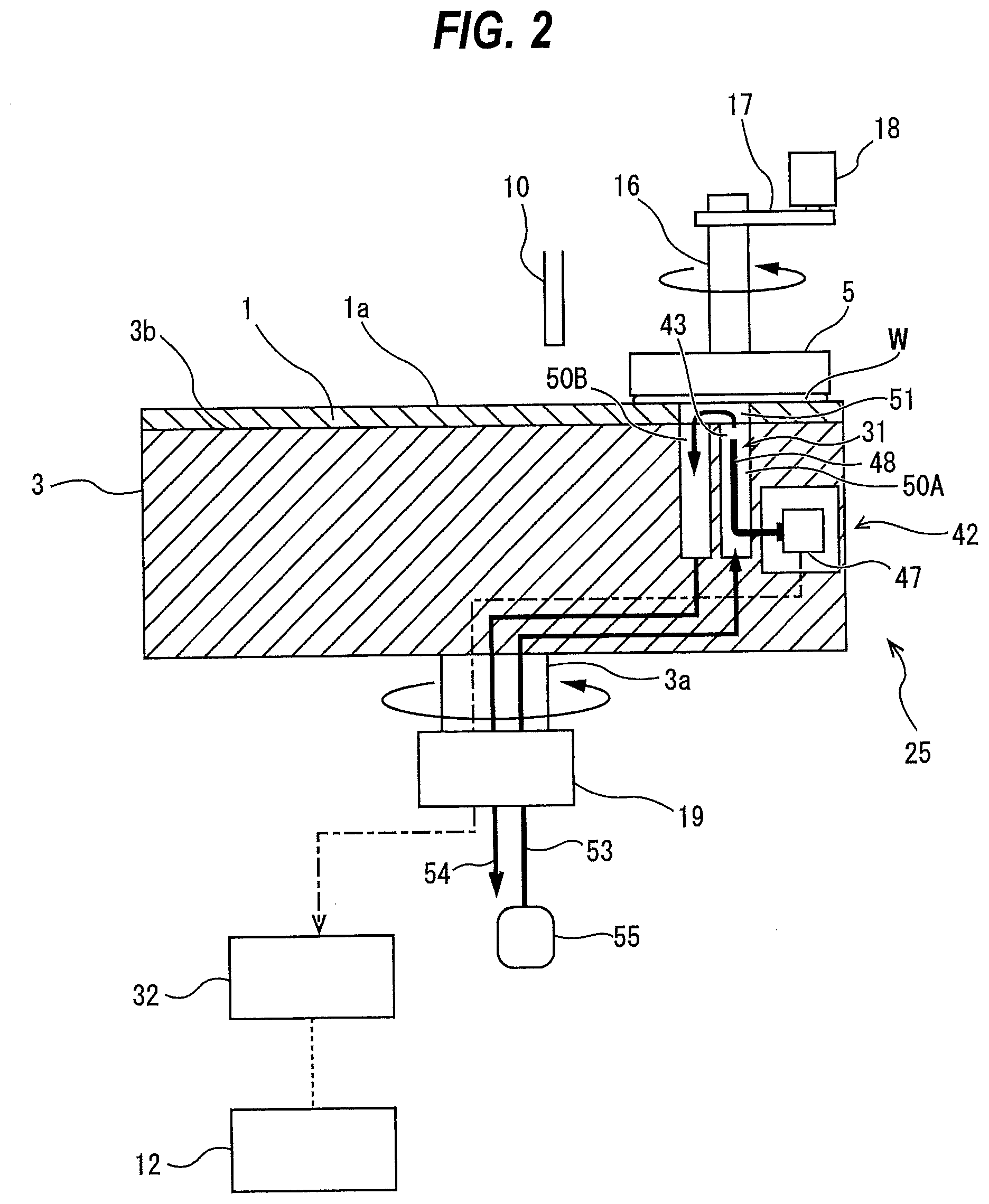
[0111] FIG. 3 is a top view of the through-hole 51 of the polishing pad 1 shown in FIG. 2. The through-hole 51 of the polishing pad 1 has an elliptical cross section. The sensor hole 50A and the drain hole 50B are adjacent to each other, and are arranged along the rotational direction of the polishing table 3. A width of the through-hole 51 of the polishing pad 1 is larger than a width of the sensor hole 50A and a width of the drain hole 50B, so that open ends of the sensor hole 50A and the drain hole 50B are located in the through-hole 51 of the polishing pad 1. The sensor head 31 is arranged in the sensor hole 50A. The water that has been supplied to the sensor hole 50A through the liquid supply passage 53 and the polishing liquid (e.g., slurry) that has been used in polishing the wafer W are drained through the drain hole 50B.
[0112] The polishing pad 1 gradually wears as polishing of wafers and dressing of the polishing pad 1 are repeated. Therefore, the polishing pad 1 is a consumable item. When the wear of the polishing pad 1 progresses to some extent, it is replaced with a new polishing pad.
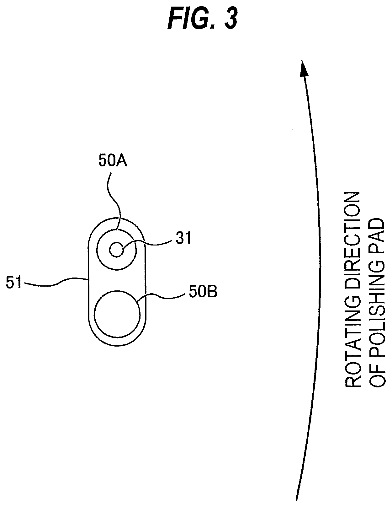
[0113] FIG. 4 is a top view showing a polishing-pad laminated structure 60 including a new polishing pad 1, FIG. 5 is a backside view of the polishing-pad laminated structure 60 shown in FIG. 4, and FIG. 6 is a cross-sectional view taken along a line B-B in FIG. 4. The polishing-pad laminated structure 60 includes the new polishing pad 1 and a release sheet 62 covering an adhesive surface 1b constituting a back surface of the polishing pad 1. The release sheet 62 is made of a flexible sheet material, such as paper or a resin film, which can be easily removed from the adhesive surface 1b. The polishing pad 1 has the through-hole 51 at a position corresponding to the position of the sensor head 31 disposed in the polishing table 3. The release sheet 62 has a through-hole 65 at the same position as the through-hole 51 of the polishing pad 1. The through-hole 51 of the polishing pad 1 are aligned with the through-hole 65 of the release sheet 62.
[0114] The release sheet 62 has the same size and the same shape as the polishing pad 1 and is attached to the entire adhesive surface 1b of the polishing pad 1. In the present embodiment, the polishing pad 1 and the release sheet 62 are in a circular shape. The release sheet 62 is divided into a first release sheet 62A and a second release sheet 62B. The first release sheet 62A and the second release sheet 62B cover the entire adhesive surface 1b of the polishing pad 1, and can be peeled off (or removed) from the adhesive surface 1b. In the present embodiment, the first release sheet 62A has a crescent shape. The first release sheet 62A has a surface area smaller than that of the second release sheet 62B. The first release sheet 62A and the second release sheet 62B are next to each other. In one embodiment, the release sheet 62 may be divided into three or more release sheets.
[0115] The through-hole 65 of the release sheet 62 are formed in the second release sheet 62B. Three release assisting projections 67B for assisting the removing of the second release sheet 62B are connected to the second release sheet 62B. One of the three release assisting projections 67B is connected to an inner edge of the second release sheet 62B, and the other two release assisting projections 67B are connected to both outer edges of the second release sheet 62B. It is noted, however, the arrangement of the release assisting projections 67B is not limited to the present embodiment. In one embodiment, only one or only two of the three release assisting projections 67B may be provided. In one embodiment, four or more release assisting projections 67B may be connected to the second release sheet 62B. A plurality of release assisting projections 67B may be connected to the inner edge of the second release sheet 62B, or three or more release assisting projections 67B may be connected to the outer edge of the second release sheet 62B. Furthermore, in one embodiment, the release assisting projection 67B may not be provided.
[0116] The release assisting projection 67B has a sheet or tape shape, and has a size that allows a user to pinch it. The release assisting projections 67B may be integral with the second release sheet 62B, or may be tape materials attached to the second release sheet 62B by adhesives. In the present embodiment, no release assisting projection is connected to the first release sheet 62A, but one or more release assisting projections for assisting the removing of the first release sheet 62A may be connected to the first peeling sheet 62A.
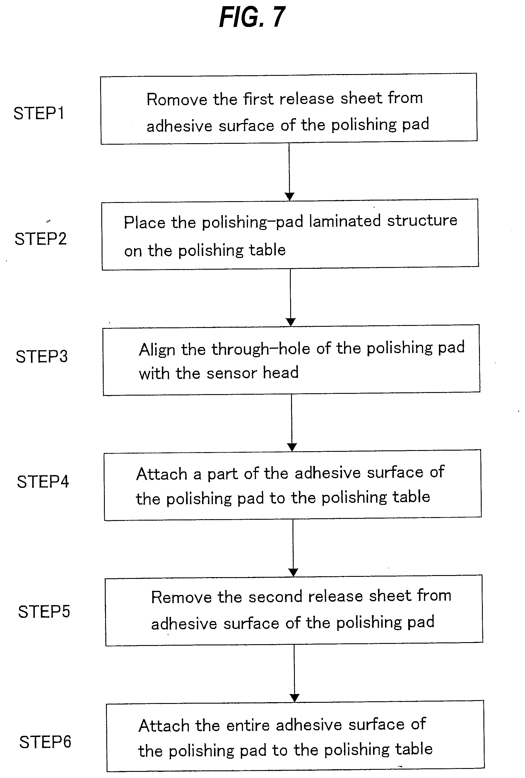
[0117] Next, operations of attaching the polishing pad 1 to the polishing table 3 will be described with reference to a flowchart of FIG. 7.
[0118] In step 1, a user peels off the first release sheet 62A from the adhesive surface (back surface) 1b of the polishing pad 1.
[0119] In step 2, the polishing-pad laminated structure 60 is placed on the pad support surface 3b of the polishing table 3 with the second release sheet 62B covering the adhesive surface 1b of the polishing pad 1. Although the first release sheet 62A has been removed from the polishing pad 1, at this stage an exposed portion of the adhesive surface 1b of the polishing pad 1 (i.e., a portion that has been covered by the first release sheet 62A) does not adhere to the pad support surface 3b of the polishing table 3. Therefore, the polishing-pad laminated structure 60 can be freely moved on the polishing table 3.
[0120] In step 3, the through-hole 51 of the polishing pad 1 is aligned with the sensor head 31 in the polishing table 3.
[0121] In step 4, with the through-hole 51 of the polishing pad 1 aligned with the sensor head 31, the exposed portion of the adhesive surface 1b of the polishing pad 1 (i.e., the portion that has been covered by the first release sheet 62A) is pressed strongly against the pad support surface 3b of the polishing table 3, whereby the part of the adhesive surface 1b of the polishing pad 1 is attached to the pad support surface 3b of the polishing table 3.
[0122] In step 5, the user grips the release assisting projections 67B with fingers and peels the second release sheet 62B from the adhesive surface 1b of the polishing pad 1. Since the release assisting projections 67B are connected to the edge of the second release sheet 62B, peeling of the second release sheet 62B begins at its edge, making it easy to remove the second release sheet 62B.
[0123] In step 6, a remaining part of the adhesive surface 1b of the polishing pad 1 is strongly pressed against the pad support surface 3b of the polishing table 3, whereby the entire adhesive surface 1b of the polishing pad 1 is attached to the pad support surface 3b of the polishing table 3.
[0124] According to the present embodiment, adjustment of the position of the polishing pad 1 with respect to the polishing table 3 is performed in a state where the first release sheet 62A having a small surface area has been removed. Since the polishing-pad laminated structure 60 can be moved relatively freely on the polishing table 3, the through-hole 51 of the polishing pad 1 can be precisely aligned with the sensor head 31 disposed in the polishing table 3. In particular, according to the present embodiment, at the time of aligning the through-hole 51, the adhesive layer 1b around the through-hole 51 remains covered with the second release sheet 62B, and therefore fine adjustment of the position of the through-hole 51 can be easily conducted. Further, immediately after the alignment between the through-hole 51 of the polishing pad 1 and the sensor head 31 is completed, the exposed portion (i.e., the portion that has been covered with the first release sheet 62A) of the adhesive surface 1b of the polishing pad 1 is pressed against the polishing table 3, so that the relative position of the polishing pad 1 with respect to the polishing table 3 can be fixed.
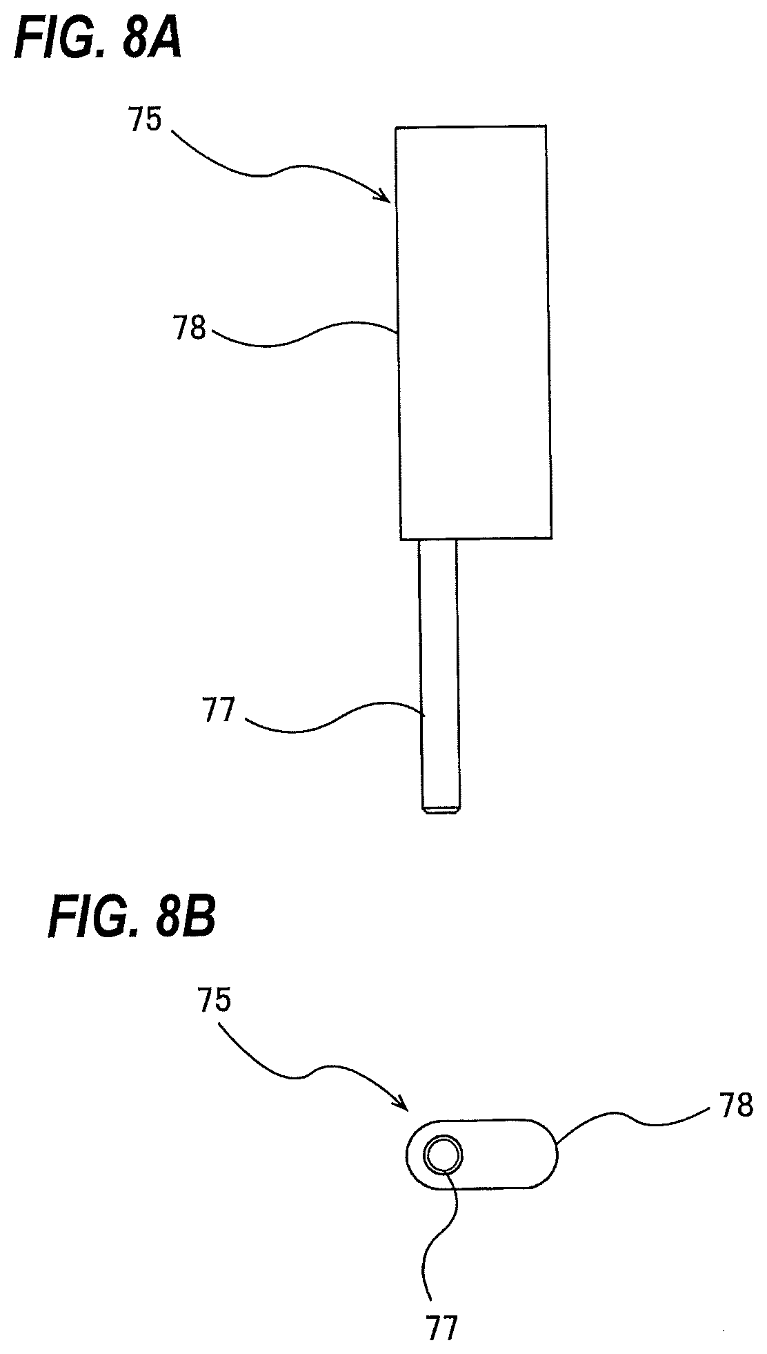
[0125] In order to facilitate the operation of aligning the through-hole 51 of the polishing pad 1 with the sensor head 31 and to improve the alignment accuracy, in one embodiment, a positioning structure 75 shown in FIGS. 8A and 8B is used. FIG. 8A is a side view of the positioning structure 75 used to position the polishing pad 1 with respect to the polishing table 3, and FIG. 8B is a bottom view of the positioning structure 75 shown in FIG. 8A. The positioning structure 75 includes a first positioning protrusion 77 configured to be able to be inserted into the drain hole 50B (see FIG. 2) as a table hole formed in the pad support surface 3b of the polishing table 3, and a second positioning protrusion 78 fixed to the first positioning protrusion 77. The second positioning protrusion 78 is located on the upper side of the first positioning protrusion 77.
[0126] The positioning structure 75 is detachably attached to the pad support surface 3b of the polishing table 3. The positioning structure 75 constitutes at least a part of a polishing-pad positioning instrument for positioning the polishing pad 1 with respect to the polishing table 3.
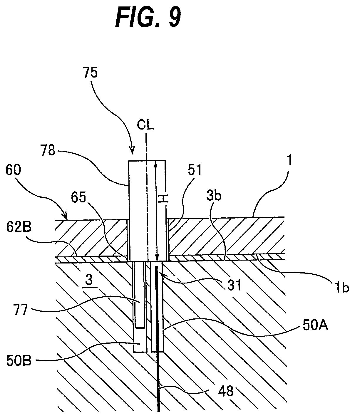
[0127] FIG. 9 is a cross-sectional view showing the positioning structure 75 with its first positioning protrusion 77 inserted into the drain hole 50B of the polishing table 3. The first positioning protrusion 77 has a cross section that can be inserted into the drain hole 50B as a table hole formed in the pad support surface 3b of the polishing table 3. The length of the first positioning protrusion 77 is shorter than the length of the drain hole 50B, so that the entire first positioning protrusion 77 can be inserted into the drain hole SOB. In the present embodiment, the first positioning protrusion 77 has a pin shape. However, the shape and the length of the first positioning protrusion 77 are not limited to the present embodiment, and are determined based on the shape and the length of the table hole formed in the pad support surface 3b.
[0128] In the present embodiment, the cross section of the first positioning protrusion 77 is smaller than the cross section of the second positioning protrusion 78. In a case where the cross section of the table hole is large, the cross section of the first positioning protrusion 77 may have the same shape and the same size as those of the cross section of the second positioning protrusion 78. Furthermore, in one embodiment, the cross section of the first positioning protrusion 77 may be larger than the cross section of the second positioning protrusion 78.
[0129] When the first positioning protrusion 77 is placed in the drain hole 50B, the second positioning protrusion 78 protrudes upward from the pad support surface 3b of the polishing table 3. The second positioning protrusion 78 has the cross-sectional shape corresponding to the cross-sectional shape of the through-hole 51 of the polishing pad 1. In the present embodiment, since the through-hole 51 of the polishing pad 1 has an elliptical cross section, the cross section of the second positioning protrusion 78 is in an elliptical shape slightly smaller than the cross section of the through-hole 51 of the polishing pad 1. A length H of the second positioning protrusion 78 along a central axis CL of the second positioning protrusion 78 is equal to or greater than the thickness of the polishing pad 1.
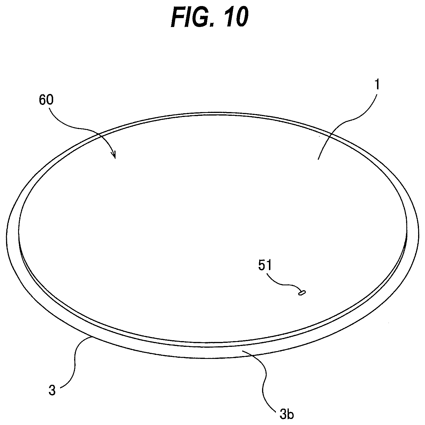
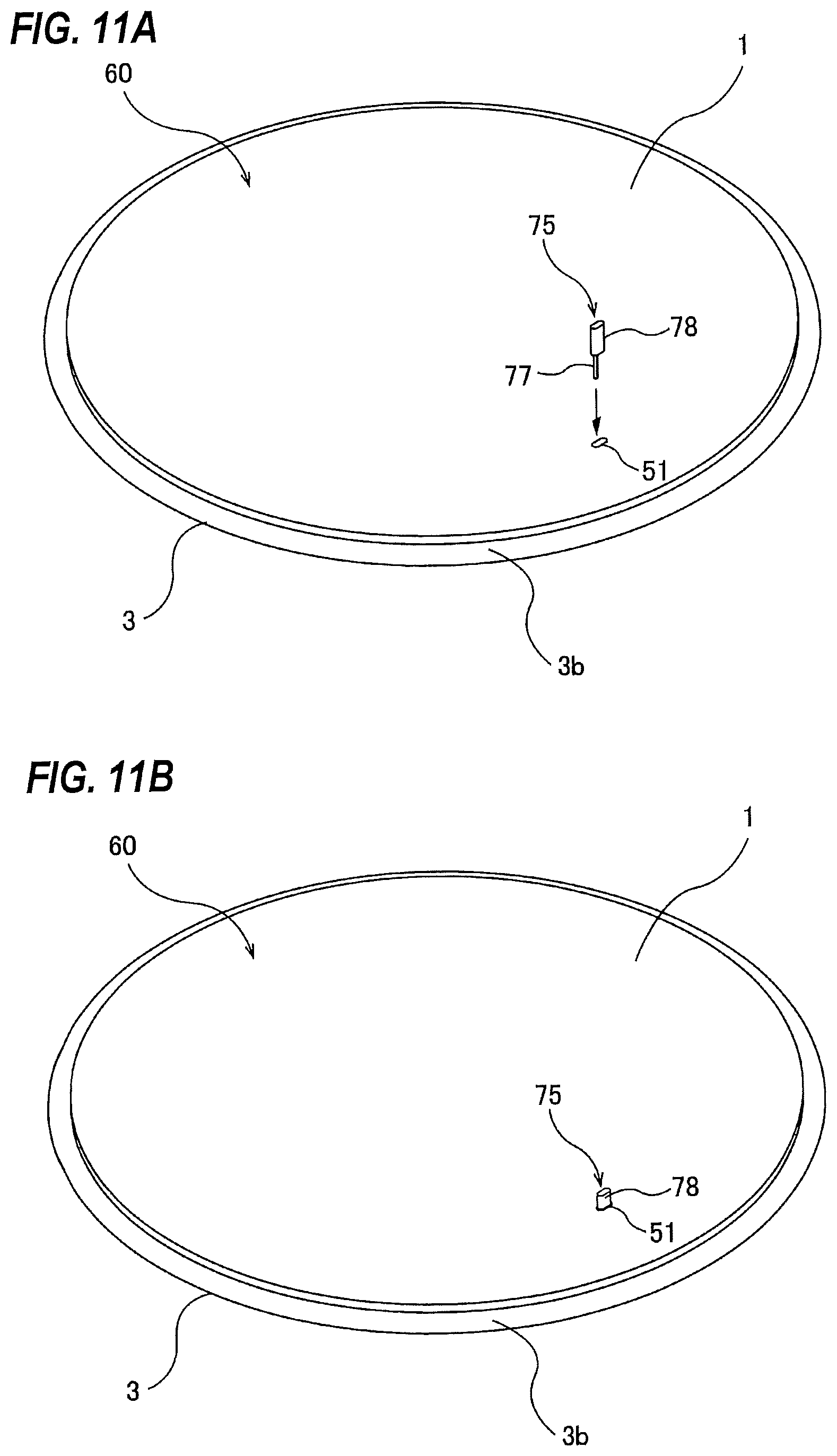
[0130] The polishing pad 1 is attached to the polishing table 3 as follows using the positioning structure 75 as a polishing-pad positioning instrument. First, as shown in FIG. 10, the polishing-pad laminated structure 60 from which the first release sheet 62A has been removed is placed on the pad support surface 3b of the polishing table 3. Next, as shown in FIGS. 11A and 11B and FIG. 9, the first positioning protrusion 77 of the positioning structure 75 is inserted into the drain hole 50B of the polishing table 3 through the through-hole 51 of the polishing pad 1 and the through-hole 65 of the second release sheet 62B. Further, the second positioning protrusion 78 is inserted into the through-hole 51 of the polishing pad 1 and the through-hole 65 of the second release sheet 62B. The through-hole 51 of the polishing pad 1 is aligned with the sensor head 31 disposed in the polishing table 3 by the second positioning protrusion 78 inserted into the through-hole 51 of the polishing pad 1.
[0131] Next, the exposed portion (i.e., the portion that has been covered by the first release sheet 62A) of the adhesive surface (back surface) 1b of the polishing pad 1 is attached to the pad support surface 3b of the polishing table 3. Thus, the relative position of the polishing-pad laminated structure 60 with respect to the polishing table 3 is fixed. Thereafter, the positioning structure 75 is removed from the polishing table 3 and the polishing pad 1. Furthermore, the second release sheet 62B is peeled off from the polishing pad 1, and the entire adhesive surface 1b of the polishing pad 1 is attached to the pad support surface 3b of the polishing table 3.
[0132] According to the present embodiment, the positioning of the polishing pad 1 with respect to the polishing table 3 is completed by inserting the second positioning protrusion 78 of the positioning structure 75 into the through-hole 51 of the polishing pad 1. Thus, the attaching work of the polishing pad 1 can be facilitated.
[0133] In one embodiment, the positioning structure 75 may be attached to the polishing table 3 before the polishing pad 1 is placed on the polishing table 3. Specifically, first, the first positioning protrusion 77 of the positioning structure 75 is inserted into the drain hole 50B of the polishing table 3. Next, the polishing-pad laminated structure 60 from which the first release sheet 62A has been removed is placed on the pad support surface 3b of the polishing table 3. At this time, the second positioning protrusion 78 is inserted into the through-hole 51 of the polishing pad 1 and the through-hole 65 of the second release sheet 62B. The through-hole 51 of the polishing pad 1 is aligned with the sensor head 31 disposed in the polishing table 3 by the second positioning protrusion 78 inserted into the through-hole 51 of the polishing pad 1. Next, the exposed portion (i.e., the portion that has been covered by the first release sheet 62A) of the adhesive surface 1b of the polishing pad 1 is attached to the pad support surface 3b of the polishing table 3. Thus, the relative position of the polishing-pad laminated structure 60 with respect to the polishing table 3 is fixed. Thereafter, the positioning structure 75 is removed from the polishing table 3 and the polishing pad 1. Furthermore, the second release sheet 62B is peeled off from the polishing pad 1, and the entire adhesive surface 1b of the polishing pad 1 is attached to the pad support surface 3b of the polishing table 3.
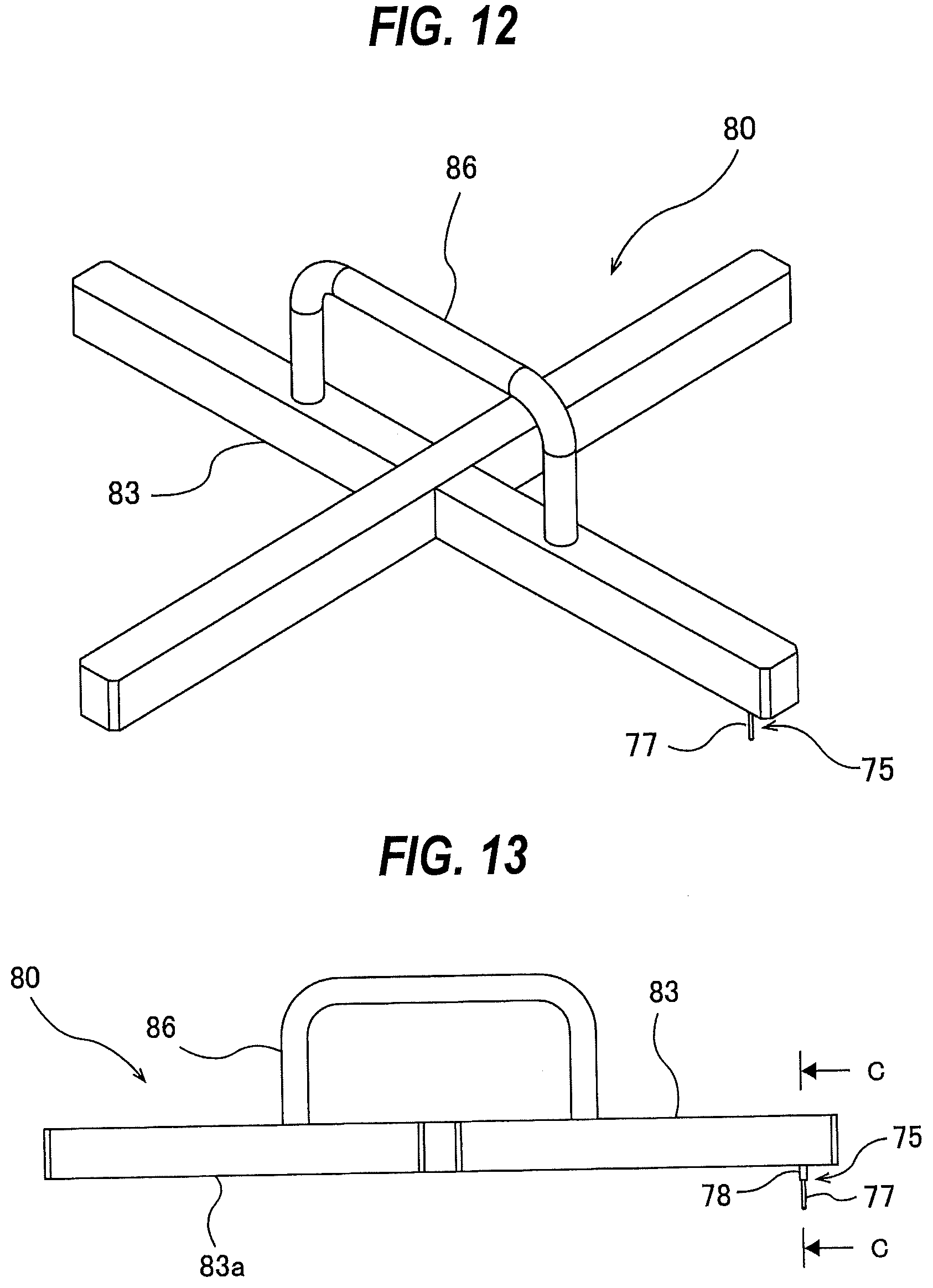
[0134] FIG. 12 is a perspective view showing another embodiment of a polishing-pad positioning instrument, FIG. 13 is a front view of the polishing-pad positioning instrument shown in FIG. 12, and FIG. 14 is a cross-sectional view taken along a line C-C of FIG. 13. In the present embodiment, a polishing-pad positioning instrument 80 includes a support structure 83 for supporting the second positioning protrusion 78 of the positioning structure 75. The support structure 83 serves as a structure for preventing the entire positioning structure 75 from falling when the first positioning protrusion 77 is inserted into the drain hole 50B of the polishing table 3. The entire first positioning protrusion 77 and the lower portion of the second positioning protrusion 78 project downward from a bottom surface 83a of the support structure 83.
[0135] In order to stabilize the posture of the positioning structure 75, the bottom surface 83a of the support structure 83 is perpendicular to the central axis CL (see FIG. 14) of the second positioning protrusion 78. In the present embodiment, the support structure 83 has a cross shape. However, the entire support structure 83 may have another shape such as a flat plate shape or a disk shape, as long as the bottom surface 83a of the support structure 83 is perpendicular to the central axis CL of the second positioning protrusion 78. In the present embodiment, a handle 86 is secured to the top of the support structure 83.
[0136] As shown in FIG. 14, the support structure 83 has a vertical hole 83b extending perpendicularly to the bottom surface 83a. The upper portion of the second positioning protrusion 78 is housed in the vertical hole 83b. The second positioning protrusion 78 is supported by the support structure 83 so as to be movable along the central axis CL of the second positioning protrusion 78. The polishing-pad positioning instrument 80 includes a spring 88 disposed between the second positioning protrusion 78 and the support structure 83. The spring 88 is located in the vertical hole 83b and configured to force the positioning structure 75 in an extending direction of the central axis CL of the second positioning protrusion 78. The structure and position of the spring 88 are not limited to this embodiment as long as the spring 88 can force the positioning structure 75 in the extending direction of the central axis CL of the second positioning protrusion 78. In the present embodiment, the extending direction of the central axis CL of the second positioning protrusion 78 is parallel to the longitudinal direction of the first positioning protrusion 77.
[0137] The polishing-pad positioning instrument 80 shown in FIG. 12 is used as follows. First, as shown in FIG. 15, the polishing-pad laminated structure 60 from which the first release sheet 62A has been removed is placed on the pad support surface 3b of the polishing table 3. Next, as shown in FIGS. 16A and 16B, the polishing-pad positioning instrument 80 is placed on the polishing pad 1. At this time, as shown in FIG. 17, the first positioning protrusion 77 is inserted into the drain hole 50B of the polishing table 3 through the through-hole 51 of the polishing pad 1 and the through-hole 65 of the second release sheet 62B. Further, the second positioning protrusion 78 is inserted into the through-hole 51 of the polishing pad 1 and the through-hole 65 of the second release sheet 62B. The through-hole 51 of the polishing pad 1 is aligned with the sensor head 31 disposed in the polishing table 3 by the second positioning protrusion 78 inserted into the through-hole 51 of the polishing pad 1.
[0138] Next, while the polishing pad 1 is being pressed against the polishing table 3 by the support structure 83 of the polishing-pad positioning instrument 80, the exposed portion (i.e., the portion that has been covered with the first release sheet 62A) of the adhesive surface 1b of the polishing pad 1 is attached to the pad support surface 3b of the polishing table 3. Thus, the relative position of the polishing-pad laminated structure 60 with respect to the polishing table 3 is fixed. When the polishing-pad positioning instrument 80 is pressed against the upper surface (polishing surface) 1a of the polishing pad 1, the support structure 83 is moved against the force of the spring 88, until the bottom surface 83a of the support structure 83 is brought into contact with the upper surface (polishing surface) 1a of the polishing pad 1. Therefore, the support structure 83 of the polishing-pad positioning instrument 80 can press the polishing pad 1 against the polishing table 3 while the first positioning protrusion 77 is inserted into the drain hole 50B.
[0139] After the exposed portion of the adhesive surface 1b of the polishing pad 1 is attached to the pad support surface 3b of the polishing table 3, the polishing-pad positioning instrument 80 is removed from the polishing table 3 and the polishing pad 1. Further, the second release sheet 62B is peeled off from the polishing pad 1, and the entire adhesive surface 1b of the polishing pad 1 is attached to the pad support surface 3b of the polishing table 3.
[0140] FIGS. 18A and 18B are perspective views each showing still another embodiment of a polishing-pad positioning instrument 80. The polishing-pad positioning instrument 80 includes a plate-shaped support structure 83 to which the positioning structure 75 is detachably attached. As shown in FIG. 18A, a slit 83c is formed in one edge of the support structure 83. This slit 83c has a shape with which the second positioning protrusion 78 of the positioning structure 75 can engage. The second positioning protrusion 78 is slid into the slit 83c, so that the positioning structure 75 is attached to the support structure 83 as shown in FIG. 18B. A string 90 is connected to the opposite edge of the support structure 83.
[0141] The polishing-pad positioning instrument 80 shown in FIGS. 18A and 18B is used as follows. First, as shown in FIGS. 19A and 19B, the bottom surface 83a of the support structure 83 is placed on the pad support surface 3b of the polishing table 3 while the first positioning protrusion 77 of the polishing-pad positioning instrument 80 is inserted into the drain hole 50B of the polishing table 3. Next, as shown in FIG. 20, the polishing-pad laminated structure 60 from which the first release sheet 62A has been peeled off is placed on the pad support surface 3b of the polishing table 3 and the support structure 83. At this time, as shown in FIG. 21, the second positioning protrusion 78 is inserted into the through-hole 51 of the polishing pad 1 and the through-hole 65 of the second release sheet 62B. The through-hole 51 of the polishing pad 1 is aligned with the sensor head 31 disposed in the polishing table 3 by the second positioning protrusion 78 inserted into the through-hole 51 of the polishing pad 1.
[0142] Next, the exposed portion (i.e., the portion that has been covered with the first release sheet 62A) of the adhesive surface 1b of the polishing pad 1 is attached to the pad support surface 3b of the polishing table 3. Thus, the relative position of the polishing-pad laminated structure 60 with respect to the polishing table 3 is fixed. The string 90 is pulled in a direction of an arrow shown in FIG. 20 to pull out the support structure 83 from the polishing table 3, thereby leaving the positioning structure 75 on the polishing table 3 as shown in FIG. 22. Next, the positioning structure 75 is removed from the polishing table 3 and the polishing pad 1. Further, the second release sheet 62B is peeled off from the polishing pad 1, and the entire adhesive surface 1b of the polishing pad 1 is attached to the pad support surface 3b of the polishing table 3.
[0143] In one embodiment, the polishing-pad positioning instrument 80 shown in FIGS. 18A and 18B may be used as follows. First, as shown in FIG. 23, the polishing-pad laminated structure 60 from which the first release sheet 62A has been removed is placed on the pad support surface 3b of the polishing table 3. Next, as shown in FIG. 24, the polishing-pad positioning instrument 80 is placed on the polishing pad 1. At this time, as shown in FIG. 25, the first positioning protrusion 77 is inserted into the drain hole 50B of the polishing table 3 through the through-hole 51 of the polishing pad 1 and the through-hole 65 of the second release sheet 62B. Further, the positioning protrusion 78 is inserted into the through-hole 51 of the polishing pad 1 and the through-hole 65 of the second release sheet 62B. The through-hole 51 of the polishing pad 1 is aligned with the sensor head 31 disposed in the polishing table 3 by the second positioning protrusion 78 inserted into the through-hole 51 of the polishing pad 1.
[0144] Next, while the polishing pad 1 is being pressed against the polishing table 3 by the support structure 83 of the polishing-pad positioning instrument 80, the exposed portion (i.e., the portion that has been covered with the first release sheet 62A) of the adhesive surface 1b of the polishing pad 1 is attached to the pad support surface 3b of the polishing table 3. Thus, the relative position of the polishing-pad laminated structure 60 with respect to the polishing table 3 is fixed. Thereafter, the polishing-pad positioning instrument 80 is removed from the polishing table 3. Further, the second release sheet 62B is peeled off from the polishing pad 1, and the entire adhesive surface 1b of the polishing pad 1 is attached to the pad support surface 3b of the polishing table 3.
[0145] FIG. 26A is a top view showing another embodiment of a polishing-pad laminated structure 60, and FIG. 26B is a backside view of the polishing-pad laminated structure 60 shown in FIG. 26A. Configurations, which are not particularly described, are the same as those of the embodiment described with reference to FIG. 4 to FIG. 6, and will not be described in duplication. In the present embodiment, a release sheet 62 is divided into a first release sheet 62A, a second release sheet 62B, and a third release sheet 62C. The first release sheet 62A is located at the center of the polishing pad 1 and extends from one side to the opposite side of the polishing pad 1. The second release sheet 62B and the third release sheet 62C are arranged to sandwich the first release sheet 62A. The first release sheet 62A has a band shape, and each of the second release sheet 62B and the third release sheet 62C has a half-moon shape. A surface area of the first release sheet 62A is smaller than a surface area of the second release sheet 62B and a surface area of the third release sheet 62C. In the present embodiment, the through-hole 51 of the polishing pad 1 are covered with the first release sheet 62A. No through-hole communicating with the through-hole 51 is formed in the release sheet 62 including the first release sheet 62A, the second release sheet 62B, and the third release sheet 62C. In one embodiment, a through-hole communicating with the through-hole 51 may be formed in the release sheet 62.
[0146] Three release assisting projections 67B are connected to the second release sheet 62B. One of the three release assisting projections 67B is connected to an inner edge of the second release sheet 62B, and the other two release assisting projections 67B are connected to both outer edges of the second release sheet 62B. It is noted, however, the arrangement of the release assisting projections 67B is not limited to the present embodiment. In one embodiment, only one or only two of the three release assisting projections 67B may be provided. In one embodiment, four or more release assisting projections 67B may be connected to the second release sheet 62B. A plurality of release assisting projections 67B may be connected to the inner edge of the second release sheet 62B, or three or more release assisting projections 67B may be connected to the outer edge of the second release sheet 62B. Further, in one embodiment, the release assisting projection 67B may not be provided.
[0147] Three release assisting projections 67C are connected to the third release sheet 62C. One of the three release assisting projections 67C is connected to an inner edge of the third release sheet 62C, and the other two release assisting projections 67C are connected to both outer edges of the third release sheet 62C. It is noted, however, the arrangement of the release assisting projections 67C is not limited to the present embodiment. In one embodiment, only one or only two of the three release assisting projections 67C may be provided. In one embodiment, four or more release assisting projections 67C may be connected to the third release sheet 62C. A plurality of release assisting projections 67C may be connected to the inner edge of the third release sheet 62C, or three or more release assisting projections 67C may be connected to the outer edge of the third release sheet 62C. Further, in one embodiment, the release assisting projection 67C may not be provided.
[0148] In the present embodiment, no release assisting projection is connected to the first release sheet 62A. However, a release assisting projection for assisting the removing of the first release sheet 62A may be connected to the first release sheet 62A.
[0149] The attaching operation of the polishing pad 1 is performed in the same manner as the flowchart shown in FIG. 7. Specifically, a user peels off the first release sheet 62A from the adhesive surface 1b of the polishing pad 1. The polishing-pad laminated structure 60 is placed on the pad support surface 3b of the polishing table 3 with the second release sheet 62B and the third release sheet 62C covering the adhesive surface 1b of the polishing pad 1. Although the first release sheet 62A has been removed from the polishing pad 1, at this stage the exposed portion of the adhesive surface 1b of the polishing pad 1 (i.e., the portion that has been covered by the first release sheet 62A) does not adhere to the pad support surface 3b of the polishing table 3.
[0150] In this embodiment, the adhesive surface 1b is exposed around the through-hole 51 of the polishing pad 1. However, the exposed area of the adhesive surface 1b is small, and the exposed portion of the adhesive surface 1b is located between the second release sheet 62B and the third release sheet 62C. As a result, even when the polishing-pad laminated structure 60 is placed on the pad support surface 3b of the polishing table 3, the exposed portion of the adhesive surface 1b is not likely to contact the pad support surface 3b. Therefore, the polishing-pad laminated structure 60 can be freely moved on the polishing table 3.
[0151] Next, the through-hole 51 of the polishing pad 1 is aligned with the sensor head 31 disposed in the polishing table 3. As described above, since the polishing-pad laminated structure 60 can be freely moved on the polishing table 3, the through-hole 51 of the polishing pad 1 can be precisely aligned with the sensor head 31. With the through-hole 51 of the polishing pad 1 aligned with the sensor head 31, the exposed portion of the adhesive surface 1b of the polishing pad 1 is strongly pressed against the pad support surface 3b of the polishing table 3, whereby the portion of the adhesive surface 1b of the polishing pad 1 is attached to the pad support surface 3b of the polishing table 3. As a result, the relative position of the polishing-pad laminated structure 60 with respect to the polishing table 3 is fixed.
[0152] The user grips the release assisting projections 67B with fingers and peels off the second release sheet 62B from the adhesive surface 1b of the polishing pad 1. A new exposed portion of the adhesive surface 1b of the polishing pad 1 is strongly pressed against the pad support surface 3b of the polishing table 3. Further, the user grips the release assisting projections 67C with fingers, and peels off the third release sheet 62C from the adhesive surface 1b of the polishing pad 1. Then, the remaining part of the adhesive surface 1b of the polishing pad 1 is strongly pressed against the pad support surface 3b of the polishing table 3, whereby the entire adhesive surface 1b of the polishing pad 1 is attached to the pad support surface 3b of the polishing table 3. In one embodiment, the third release sheet 62C may be removed from the adhesive surface 1b of the polishing pad 1, and then the second release sheet 62B may be removed from the adhesive surface 1b of the polishing pad 1.
[0153] FIG. 27A is a top view showing still another embodiment of a polishing-pad laminated structure 60, and FIG. 27B is a backside view of the polishing-pad laminated structure 60 shown in FIG. 27A. Configurations, which are not particularly described, are the same as those of the embodiment described with reference to FIG. 4 to FIG. 6, and will not be described in duplication. A release sheet 62 is divided into a first release sheet 62A, a second release sheet 62B, and a third release sheet 62C. In the present embodiment, the through-hole 51 of the polishing pad 1 are covered with the first release sheet 62A. No through-hole communicating with the through-hole 51 is formed in the release sheet 62 including the first release sheet 62A, the second release sheet 62B, and the third release sheet 62C. In one embodiment, a through-hole communicating with the through-hole 51 may be formed in the release sheet 62.
[0154] The first release sheet 62A has a rectangular shape. The entire first release sheet 62A is surrounded by the second release sheet 62B and the third release sheet 62C. Each of the second release sheet 62B and the third release sheet 62C has a half-moon shape. A surface area of the first release sheet 62A is smaller than a surface area of the second release sheet 62B and a surface area of the third release sheet 62C.
[0155] Three release assisting projections 67B are connected to the second release sheet 62B. One of the three release assisting projections 67B is connected to an inner edge of the second release sheet 62B, and the other two release assisting projections 67B are connected to both outer edges of the second release sheet 62B. It is noted, however, the arrangement of the release assisting projections 67B is not limited to the present embodiment. In one embodiment, only one or only two of the three release assisting projections 67B may be provided. In one embodiment, four or more release assisting projections 67B may be connected to the second release sheet 62B. A plurality of release assisting projections 67B may be connected to the inner edge of the second release sheet 62B, or three or more release assisting projections 67B may be connected to the outer edge of the second release sheet 62B. Further, in one embodiment, the release assisting projection 67B may not be provided.
[0156] Three release assisting projections 67C are connected to the third release sheet 62C. One of the three release assisting projections 67C is connected to an inner edge of the third release sheet 62C, and the other two release assisting projections 67C are connected to both outer edges of the third release sheet 62C. It is noted, however, the arrangement of the release assisting projections 67C is not limited to the present embodiment. In one embodiment, only one or only two of the three release assisting projections 67C may be provided. In one embodiment, four or more release assisting projections 67C may be connected to the third release sheet 62C. A plurality of release assisting projections 67C may be connected to the inner edge of the third release sheet 62C, or three or more release assisting projections 67C may be connected to the outer edge of the third release sheet 62C. Further, in one embodiment, the release assisting projection 67C may not be provided.
[0157] In the present embodiment, no release assisting projection is connected to the first release sheet 62A. However, a release assisting projection for assisting the removing of the first release sheet 62A may be connected to the first peeling sheet 62A.
[0158] The attaching operation of the polishing pad 1 is performed in the same manner as the embodiment shown in FIGS. 26A and 26B, and thus repetitive descriptions thereof will not be omitted.
[0159] Also in this embodiment, the adhesive surface 1b is exposed around the through-hole 51 of the polishing pad 1, but the exposed area of the adhesive surface 1b is small, and the entire exposed portion of the adhesive surface 1b is surrounded by the second release sheet 62B and the third release sheet 62C. As a result, when the polishing-pad laminated structure 60 is placed on the pad support surface 3b of the polishing table 3, the exposed portion of the adhesive surface 1b is not likely to contact the pad support surface 3b. Therefore, the polishing-pad laminated structure 60 can be freely moved on the polishing table 3.
[0160] The positioning structure 75 as the polishing-pad positioning instrument shown in FIGS. 8A and 8B, the polishing-pad positioning instrument 80 shown in FIG. 12, and the polishing-pad positioning instrument 80 shown in FIGS. 18A and 18B can be used to attach the polishing pad 1 shown in FIG. 26A and FIG. 26B and the polishing pad 1 shown in FIG. 27A and FIG. 27B to the polishing pad 3.
[0161] Although only one sensor head 31 is provided in the polishing table 3 in the embodiments described above, the present invention can be applied to a polishing apparatus including a polishing table 3 in which a plurality of sensor heads 31 are disposed as shown in FIG. 28. Two sensor heads 31 are arranged in the embodiment shown in FIG. 28, while the polishing apparatus may include three or more sensor heads 31, and the polishing pad 1 may have three or more through-holes 51.
[0162] FIG. 29A is a top view showing an embodiment of a polishing-pad laminated structure 60 used for the polishing table 3 in which two sensor heads 31 are disposed, and FIG. 29B is a top view of the polishing-pad laminated structure 60 shown in FIG. 29A. Configurations, which are not particularly described, are the same as those of the embodiment described with reference to FIG. 4 to FIG. 6, and will not be described in duplication. As shown in FIG. 29A, a polishing pad 1 has two through-holes 51 corresponding to the two sensor heads 31. Positions of these two through-holes 51 correspond to positions of the two sensor heads 31 in the polishing table 3. Further, as shown in FIG. 29B, a release sheet 62 has two through-holes 65 at the same positions as those of the through-holes 51 of the polishing pad 1.
[0163] The attaching operation of the polishing pad 1 shown in FIG. 29A is performed using a polishing-pad positioning instrument including two positioning structures 75. More specifically, the attaching operation of the polishing pad 1 shown in FIG. 29A is carried out in the same manner as the embodiment described with reference to the flowchart shown in FIG. 7, or the embodiment described with reference to FIGS. 10 to 11B, or the embodiment described with reference to FIGS. 15 to 17, or the embodiment described with reference to FIGS. 19A to 22, or the embodiment described with reference to FIGS. 23 to 25.
[0164] FIG. 30 is a perspective view showing an embodiment of a polishing-pad positioning instrument 80 suitable for the polishing-pad laminated structure 60 shown in FIGS. 29A and 29B, FIG. 31 is a front view of the polishing-pad positioning instrument 80 shown in FIG. 30, and FIG. 32 is a cross-sectional view taken along a line D-D of FIG. 31. Configurations of the present embodiment, which are not particularly described, are the same as those of the embodiment described with reference to FIGS. 12 to 14, and thus repetitive descriptions will be omitted.
[0165] The polishing-pad positioning instrument 80 of the present embodiment includes two positioning structures 75. The positions of these positioning structures 75 correspond to the positions of the two sensor heads 31 installed in the polishing table 3. The method of using the polishing-pad positioning instrument 80 according to the present embodiment is the same as the embodiment described with reference to FIGS. 15 to 17, and thus repetitive descriptions will be omitted.
[0166] FIGS. 33A and 33B are perspective views each showing another embodiment of a polishing-pad positioning instrument 80 suitable for the polishing-pad laminated structure 60 shown in FIGS. 29A and 29B. Configurations of the present embodiment, which are not particularly described, are the same as those of the embodiment described with reference to FIGS. 18A and 18B, and thus repetitive descriptions will be omitted.
[0167] The polishing-pad positioning instrument 80 of the present embodiment includes two positioning structures 75 detachably attached to a support structure 83. More specifically, two slits 83c, with which the second positioning protrusions 78 of the positioning structures 75 engage, are formed in one edge of the support structure 83. The second positioning protrusions 78 of the respective positioning structures 75 are slid into the slits 83c, so that the two positioning structures 75 are attached to the support structure 83, as shown in FIG. 33B. The method of using the polishing-pad positioning instrument 80 according to the present embodiment is the same as the embodiment described with reference to FIGS. 19A to 22 or the embodiment described with reference to FIGS. 23 to 25, and thus repetitive descriptions will be omitted.
[0168] FIG. 34 is a perspective view showing another embodiment of a polishing-pad positioning instrument 80 suitable for the polishing-pad laminated structure 60 shown in FIGS. 29A and 29B, and FIG. 35 is a front view of the polishing-pad positioning instrument 80 shown in FIG. 34. Configurations of the present embodiment, which are not particularly described, are the same as those of the embodiment described with reference to FIGS. 33A and 33B, and thus repetitive descriptions will be omitted.
[0169] The polishing-pad positioning instrument 80 of the present embodiment has a handle 86. This handle 86 includes two pedestals 93 for supporting the second positioning protrusions 78 of the two positioning structures 75, respectively, and a rod 94 extending between the pedestals 93. Both ends of the rod 94 are fixed to the two pedestals 93, respectively. Each pedestal 93 has a vertical hole 93a extending perpendicularly to a bottom surface thereof, so that the corresponding second positioning protrusion 78 can be fitted into the vertical hole 93a. As shown in FIG. 35, the handle 86 is placed on the polishing-pad laminated structure 60. The upper portions of the second positioning protrusions 78, extending through the through-holes 51 of the polishing-pad laminated structure 60, are inserted into the vertical holes 93a of the pedestals 93, respectively.
[0170] The polishing-pad positioning instrument 80 shown in FIG. 34 is used as follows. First, as shown in FIGS. 36A and 36B, the bottom 83a of the support structure 83 is placed on the pad support surface 3b of the polishing table 3 while the first positioning protrusions 77 of the polishing-pad positioning instrument 80 are inserted into the drain holes 50B of the polishing table 3. Next, as shown in FIG. 37, the polishing-pad laminated structure 60 from which the first release sheet 62A has been peeled off is placed on the pad support surface 3b of the polishing table 3 and the support structure 83. At this time, the second positioning protrusions 78 are inserted into the through-holes 51 of the polishing pad 1 and the through-holes 65 of the second release sheet 62B (see FIG. 21). The through-holes 51 of the polishing pad 1 are aligned with the sensor heads 31, respectively, disposed in the polishing table 3 by the second positioning protrusions 78 inserted into the through-holes 51 of the polishing pad 1.
[0171] The exposed portion (i.e., the portion that has been covered with the first release sheet 62A) of the adhesive surface 1b of the polishing pad 1 is attached to the pad support surface 3b of the polishing table 3. Thus, the relative position of the polishing-pad laminated structure 60 with respect to the polishing table 3 is fixed. As shown in FIG. 38, the handle 86 is attached to the positioning structures 75. More specifically, the second positioning protrusions 78, protruding upward from the polishing-pad laminated structure 60, are inserted into the vertical holes 93a (see FIG. 35) of the pedestals 93. While the handle 86 is being pressed against the polishing-pad laminated structure 60 so that the positioning structures 75 do not fall down, the support structure 83 is pulled out of the polishing table 3 by pulling the string 90 in the direction of the arrow shown in FIG. 38. Next, the handle 86 and the positioning structures 75 are removed from the polishing-pad laminated structure 60. Furthermore, the second release sheet 62B is peeled off from the polishing pad 1, and the entire adhesive surface 1b of the polishing pad 1 is attached to the pad support surface 3b of the polishing table 3.
[0172] FIG. 39A is a top view showing another embodiment of a polishing-pad laminated structure 60 used for the polishing table 3 in which the two sensor heads 31 are arranged, and FIG. 39B is a backside view of the polishing-pad laminated structure 60 shown in FIG. 39A. Configurations, which are not particularly described, are the same as those of the embodiment described with reference to FIGS. 26A and 26B, and thus the description thereof will not be repeated. As shown in FIG. 39A, a polishing pad 1 has two through-holes 51 corresponding to the two sensor heads 31. The positions of these two through-holes 51 correspond to the positions of the two sensor heads 31 in the polishing table 3. As shown in FIG. 39B, a release sheet 62 is divided into a first release sheet 62A, a second release sheet 62B, and a third release sheet 62C.
[0173] FIG. 40A is a top view showing still another embodiment of a polishing-pad laminated structure 60 used for the polishing table 3 in which the two sensor heads 31 are arranged, and FIG. 40B is a backside view of the polishing-pad laminated structure 60 shown in FIG. 40A. Configurations, which are not particularly described, are the same as those of the embodiment described with reference to FIGS. 27A and 27B, and thus the description thereof will not be repeated. As shown in FIG. 40A, a polishing pad 1 has two through-holes 51 corresponding to the two sensor heads 31. The positions of these two through-holes 51 correspond to the positions of the two sensor heads 31 in the polishing table 3. As shown in FIG. 40B, a release sheet 62 is divided into two first release sheets 62A, a second release sheet 62B, and a third release sheet 62C.
[0174] The polishing-pad positioning instrument 80 shown in FIG. 30, the polishing-pad positioning instrument 80 shown in FIGS. 33A and 33B, and the polishing-pad positioning instrument 80 shown in FIGS. 34 and 35 can be used for attaching the polishing pad 1 shown in FIG. 39A and the polishing pad 1 shown in FIG. 40A to the pad support surface 3b of the polishing table 3.
[0175] The number and positions of the through-holes 51 of the polishing pad 1 are determined based on the number and positions of the sensor heads 31 disposed in the polishing table 3. The number and position of the sensor heads 31 are not limited to the embodiments described above. In one embodiment, three or more sensor heads 31 may be arranged. The same number of through-holes 51 of the polishing pad 1 is formed at the same positions of the sensor heads 31. For example, as shown in FIGS. 41A, 41B, 42A, 42B, 43A, and 43B, a polishing pad 1 may have three through-holes 51.
[0176] Furthermore, the number of through-holes 51 of the polishing pad 1 may be larger than the number of sensor heads 31 arranged in the polishing table 3. For example, a polishing pad 1 having three through-holes 51 may be attached to the polishing table 3 in which the two sensor heads 31 are disposed.
[0177] FIG. 44A is a perspective view showing another embodiment of a positioning structure 75, FIG. 44B is a side view of the positioning structure 75 shown in FIG. 44A, and FIG. 44C is bottom view of the positioning structure 75 shown in FIG. 44A. Configurations of the present embodiment, which are not particularly described, are the same as those of the embodiment described with reference to FIGS. 8A, 8B, and 9, and thus repetitive descriptions will be omitted.
[0178] The positioning structure 75 has a third positioning protrusion 100 connected to the upper portion of the second positioning protrusion 78. The third positioning protrusion 100 has a cylindrical shape and is concentric with the second positioning protrusion 78. Specifically, the central axis of the third positioning protrusion 100 coincides with the central axis CL of the second positioning protrusion 78. In one embodiment, the third positioning protrusion 100 may have the same cross-sectional shape as that of the second positioning protrusion 78. A length of the third positioning protrusion 100 along the central axis CL of the second positioning protrusion 78 is larger than a length of the second positioning protrusion 78 and larger than a length of the first positioning protrusion 77.
[0179] The third positioning protrusion 100 has a mark 102 indicating the position of the first positioning protrusion 77 with respect to the central axis CL of the second positioning protrusion 78. In the present embodiment, the mark 102 is constituted by a cut formed in the outer peripheral surface of the third positioning protrusion 100. However, the shape of the mark 102 is not limited to the present embodiment. For example, the mark 102 may be a groove formed in the outer peripheral surface of the third positioning protrusion 100.
[0180] The mark 102 is located outside the first positioning protrusion 77 in the radial direction of the third positioning protrusion 100. The mark 102 extends in the longitudinal direction of the third positioning protrusion 100 over the entire third positioning protrusion 100. The first positioning protrusion 77 is eccentric with respect to the central axis CL of the second positioning protrusion 78. When the first positioning protrusion 77 is inserted into the drain hole 50B (see, for example, FIG. 9) of the polishing table, a user can know the position of the first positioning protrusion 77 from the mark 102.
[0181] The third positioning protrusion 100 has a recessed portion 105 formed in the outer peripheral surface of the third positioning protrusion 100. In the present embodiment, the recessed portion 105 is formed from a part of a lateral hole passing through the third positioning protrusion 100, but the shape of the recessed portion 105 is not limited to this embodiment. For example, the lateral hole that constitutes the recessed portion 105 may not penetrate the third positioning protrusion 100. In another example, the recessed portion 105 may be an annular groove extending in the circumferential direction of the outer circumferential surface of the third positioning protrusion 100.
[0182] The entire positioning structure 75 including the first positioning protrusion 77, the second positioning protrusion 78, and the third positioning protrusion 100 is made of metal such as stainless steel. In the present embodiment, the first positioning protrusion 77, the second positioning protrusion 78, and the third positioning protrusion 100 constitute an integral structure.
[0183] FIG. 45 is a perspective view showing an embodiment of a support structure 83 for supporting the positioning structure 75 shown in FIGS. 44A to 44C, and FIG. 46 is a view of the positioning structure 75 and the support structure 83 shown in FIG. 45 as viewed obliquely from below. The polishing-pad positioning instrument 80 of the present embodiment includes the single positioning structure 75 and the single support structure 83 for supporting the third positioning protrusion 100 of the positioning structure 75. The support structure 83 includes a pedestal 111 for supporting the third positioning protrusion 100, a bridge 112 fixed to the pedestal 111, and two legs 114 fixed to a bottom surface of the bridge 112.
[0184] The entire positioning structure 75 including the first positioning protrusion 77, the second positioning protrusion 78, and the third positioning protrusion 100 is supported by the pedestal 111. In one embodiment, the pedestal 111 and the bridge 112 may constitute an integral structure. The two legs 114 are fixed to both sides of the bottom surface of the bridge 112. Each leg 114 protrudes downward from the bottom surface of the bridge 112, and the bottom surface of the bridge 112 is located above a bottom surface of the leg 114. The legs 114 are made of resin, such as polytetrafluoroethylene (PTFE). In one embodiment, the bridge 112 and the legs 114 may constitute an integral structure. Furthermore, in one embodiment, the pedestal 111, the bridge 112, and the legs 114 may constitute an integral structure.
[0185] The pedestal 111 is fixed to the central portion of a top surface of the bridge 112. The two legs 114 are apart from each other, and the pedestal 111 and the positioning structure 75 are located between the two legs 114. Knobs 115 are fixed on both sides of the top surface of the bridge 112. These knobs 115 are located above the two legs 114, respectively.
[0186] Each leg 114 has a flat bottom surface 114a. The bottom surfaces 114a of the two legs 114 are located in the same plane. The bottom surfaces 114a are separated from each other, and the first positioning protrusion 77 and the second positioning protrusion 78 of the positioning structure 75 are located at a midpoint between the two bottom surfaces 114a. The support structure 83 has a vertical hole 120 extending perpendicularly to the bottom surfaces 114a of the legs 114. The vertical hole 120 is formed in the pedestal 111 and the bridge 112, and extends through the pedestal 111 and the bridge 112.
[0187] The entire third positioning protrusion 100 of the positioning structure 75 has a diameter smaller than a diameter of the vertical hole 120. The third positioning protrusion 100 is inserted into the vertical hole 120 of the support structure 83 and is movably supported by the vertical hole 120. The entire positioning structure 75 extends through the pedestal 111 and the bridge 112.
[0188] The entire positioning structure 75, including the first positioning protrusion 77, the second positioning protrusion 78, and the third positioning protrusion 100, is vertically movable relative to the support structure 83. Specifically, the positioning structure 75 is supported by the support structure 83 so as to be movable in the longitudinal direction of the first positioning protrusion 77. The longitudinal direction of the first positioning protrusion 77 is parallel to the central axis CL (see FIG. 44B) of the second positioning protrusion 78. The positioning structure 75 is movable in the direction perpendicular to the bottom surfaces 114a of the legs 114 (i.e., in the longitudinal direction of the first positioning protrusion 77), but the movement of positioning structure 75 in a direction parallel to the bottom surfaces 114a of the legs 114 is restricted by the pedestal 111 (i.e., by the support structure 83). Accordingly, the entire positioning structure 75 is allowed to move only in the direction perpendicular to the bottom surfaces 114a of the legs 114.
[0189] The support structure 83 further includes a stopper 128 for fixing the relative position of the positioning structure 75 with respect to the support structure 83. The stopper 128 has an engagement portion 129 which can be inserted into the recessed portion 105 of the third positioning protrusion 100. The stopper 128 is supported by the pedestal 111. More specifically, the stopper 128 is movably supported by the pedestal 111 in directions closer to and away from the third positioning protrusion 100 of the positioning structure 75.
[0190] FIG. 47 is a sectional view taken along a line E-E of FIG. 45. When the stopper 128 is moved toward the third positioning protrusion 100, the engagement portion 129 of the stopper 128 is inserted into the recessed portion 105 of the third positioning protrusion 100, whereby the engagement portion 129 of the stopper 128 engages with the recessed portion 105 of the third positioning protrusion 100. The relative position of the positioning structure 75 with respect to the support structure 83 is fixed by the engagement of the stopper 128 and the third positioning protrusion 100.
[0191] As can be seen from FIG. 47, a distance L1 from the bottom surface 114a of the leg 114 (i.e., the bottom surface of the support structure 83) to a top surface of the engagement portion 129 is longer than a distance L2 from the tip end of the first positioning protrusion 77 to the upper surface of the recessed portion 105. Therefore, the tip end of the first positioning protrusion 77 when the stopper 128 engages with the third positioning protrusion 100 is at a position higher than the bottom surfaces 114a of the legs 114 (i.e., the bottom surface of the support structure 83). Thus, the stopper 128 can prevent the first positioning protrusion 77 from protruding below the bottom surface of the support structure 83, and can prevent the first positioning protrusion 77 from being bent or broken.
[0192] As shown in FIG. 48, when the stopper 128 is moved in the direction away from the third positioning protrusion 100, the engagement portion 129 of the stopper 128 is disengaged from the recessed portion 105 of the third positioning protrusion 100. As a result, the engagement between the stopper 128 and the third positioning protrusion 100 is released, so that the entire positioning structure 75 can move relative to the support structure 83.
[0193] Next, an example of operations of attaching the polishing pad 1 to the polishing table 3 using the polishing-pad positioning instrument 80 described with reference to FIGS. 44 to 48 will be described. In this example, the polishing-pad laminated structure 60 of the embodiment shown in FIG. 39A and FIG. 39B is used, while the polishing-pad positioning instrument 80 according to this embodiment can be used to attach another type of polishing-pad laminated structure to the polishing table 3.
[0194] Although the polishing-pad laminated structure 60 described below does not have the release assisting projection, the release assisting projections 67B and 67C shown in FIGS. 39A and 39B may be connected to the second release sheet 62B and the third release sheet 62C, respectively.
[0195] First, as shown in FIG. 49, the first release sheet 62A is removed from the adhesive surface 1b of the polishing pad 1, while the second release sheet 62B and the third release sheet 62C remain as they are on the adhesive surface 1b of the polishing pad 1. As shown in FIG. 50, the polishing-pad laminated structure 60 from which the first release sheet 62A has been removed is placed on the pad support surface 3b of the polishing table 3. At this stage, the exposed portion (i.e., the portion that has been covered by the first release sheet 62A) of the adhesive surface 1b of the polishing pad 1 does not adhere to the pad support surface 3b of the polishing table 3. Therefore, the polishing-pad laminated structure 60 can be freely moved on the polishing table 3.
[0196] Next, as shown in FIGS. 51A and 51B and FIG. 52, the first positioning protrusion 77 of the positioning structure 75 is inserted into the drain hole (or the table hole) 50B of the polishing table 3 through one of the two through-holes 51 of the polishing pad 1, and then the second positioning protrusion 78 is inserted into the through-hole 51 of the polishing pad 1. The through-hole 51 of the polishing pad 1 is aligned with the sensor head 31 disposed in the polishing table 3 by the second positioning protrusion 78 inserted into the through-hole 51 of the polishing pad 1.
[0197] The third positioning protrusion 100 is located above the polishing-pad laminated structure 60. A user can check the relative position of the first positioning protrusion 77 with respect to the central axis CL (see FIG. 52) of the second positioning protrusion 78 based on the mark 102 formed in the third positioning protrusion 100.
[0198] Next, as shown in FIGS. 53A and 53B, the third positioning protrusion 100 of the positioning structure 75, which is standing by itself on the polishing table 3, is inserted into the vertical hole 120 of the support structure 83. The stopper 128 is at a position not in contact with the third positioning protrusion 100. Since the entirety of the third positioning protrusion 100 of the positioning structure 75 has the diameter smaller than the diameter of the vertical hole 120, the third positioning protrusion 100 of the positioning structure 75, which is standing by itself on the polishing table 3, can be inserted into the vertical hole 120 of the support structure 83. The positioning structure 75 is supported by the support structure 83, and can prevent the positioning structure 75 from being inclined at the time of position adjustment of the polishing-pad laminated structure 60.
[0199] As shown in FIG. 53B, a distance L3 between the two legs 114 of the support structure 83 is larger than a width of the first release sheet 62A (see FIG. 49). The two legs 114 are positioned away from the exposed portion (i.e., the portion that has been covered by the first release sheet 62A) of the adhesive surface (back surface) 1b of the polishing pad 1. In other words, the two legs 114 are positioned over the second release sheet 62B and the third release sheet 62C covering the adhesive surface (back surface) 1b of the polishing pad 1. The support structure 83 placed in such a position can prevent the exposed portion (i.e., the portion that has been covered with the first release sheet 62A) of the adhesive surface (back surface) 1b of the polishing pad 1 from adhering to the support surface 3b of the polishing table 3. The user can finely adjust the position of the polishing-pad laminated structure 60 while supporting the positioning structure 75 with the support structure 83.
[0200] Next, as shown in FIGS. 54A and 54B and FIG. 52, a first positioning protrusion 77 of another positioning structure 75 is inserted into the other drain hole (table hole) 50B of the polishing table 3 through the other one of the two through-holes 51 of the polishing pad 1, and then a second positioning protrusion 78 of the other positioning structure 75 is inserted into the other through-hole 51. This through-hole 51 of the polishing pad 1 is aligned with the sensor head 31 disposed in the polishing table 3 by the second positioning protrusion 78 inserted into the through-hole 51 of the polishing pad 1.
[0201] Next, as shown in FIGS. 55A and 55B, the third positioning protrusion 100 of the positioning structure 75, which is standing by itself on the polishing table 3, is inserted into a vertical hole 120 of another support structure 83. A stopper 128 is at a position not in contact with the third positioning protrusion 100. As well as the support structure 83 that has been disposed previously, two legs 114 of the support structure 83 are placed at positions away from the exposed portion (i.e., the portion that has been covered with the first release sheet 62A) of the adhesive surface (back surface) 1b of the polishing pad 1.
[0202] Next, the exposed portion (i.e., the portion that has been covered by the first release sheet 62A) of the adhesive surface (back surface) 1b of the polishing pad 1 is attached to the pad support surface 3b of the polishing table 3. Thus, the relative position of the polishing-pad laminated structure 60 with respect to the polishing table 3 is fixed. Thereafter, the two support structures 83 and the two positioning structures 75 are removed from the polishing table 3 and the polishing pad 1. Furthermore, as shown in FIG. 56, the second release sheet 62B and the third release sheet 62C are removed from the polishing pad 1, and the entire adhesive surface 1b of the polishing pad 1 is attached to the pad support surface 3b of the polishing table 3.
[0203] According to the present embodiment, each positioning structure 75 is supported by each support structure 83. Such a combination of the single positioning structure 75 and the single support structure 83 is flexible in the versatility of the arrangement of the plurality of drain holes (table holes) 50B formed in the polishing table 3. For example, even when the polishing pad is attached to a polishing table having a different arrangement of drain holes (table holes) 50B from the present embodiment, a combination of the two support structures 83 and the two positioning structures 75 of the present embodiment can be used. When a polishing pad having three through-holes is to be attached to a polishing table having three drain holes (table holes), three sets of the positioning structures 75 and the support structures 83 are used.
[0204] FIG. 57A is a perspective view showing another embodiment of a positioning structure 75, FIG. 57B is a side view of the positioning structure 75 shown in FIG. 57A, and FIG. 57C is a bottom view of the positioning structure 75 shown in FIG. 57A. Configurations of the present embodiment, which are not particularly described, are the same as those of the embodiment described with reference to FIGS. 44A to 44C, and thus the descriptions thereof will not be repeated.
[0205] A third positioning protrusion 100 has a flange 130 at a top of the third positioning protrusion 100. The flange 130 is provided so as to prevent the positioning structure 75 from falling off a support structure 83.
[0206] FIG. 58 is a perspective view showing one embodiment of the support structure 83 for supporting positioning structures 75, one of which is shown in FIGS. 57A to 57C, and FIG. 59 is a view of the positioning structures 75 and the support structure 83 shown in FIG. 58 as viewed obliquely from below. Configurations of the present embodiment, which are not particularly described, are the same as those of the embodiment described with reference to FIGS. 45 and 46, and therefore the descriptions thereof will not be repeated.
[0207] The polishing-pad positioning instrument 80 according to this embodiment includes the two positioning structures 75 and the single support structure 83 for supporting the third positioning protrusions 100 of the two positioning structures 75. The support structure 83 includes a pedestal 111 for supporting the two third positioning protrusions 100, a bridge 112 fixed to the pedestal 111, and two legs 114 fixed to a bottom surface of the bridge 112.
[0208] The entire positioning structures 75, each including the first positioning protrusion 77, the second positioning protrusion 78, and the third positioning protrusion 100, are supported by the pedestal 111. The two positioning structures 75 are located at both ends of the pedestal 111. The pedestal 111 is fixed to an upper surface of the bridge 112, and protrudes from both sides of the bridge 112. The two legs 114 are apart from each other, and the pedestal 111 and the positioning structures 75 are located between the two legs 114. A handle 132 is fixed to an upper surface of the pedestal 111.
[0209] The support structure 83 has two vertical holes 120 extending perpendicularly to bottom surfaces 114a of the legs 114. The vertical holes 120 are located at both ends of the pedestal 111, and extend through the pedestal 111. The third positioning protrusions 100 of the positioning structures 75 are inserted into the two vertical holes 120, respectively, and are movably supported by the vertical holes 120. The entire positioning structures 75 extend through the pedestal 111. Each positioning structure 75 including the first positioning protrusion 77, the second positioning protrusion 78, and the third positioning protrusion 100 is supported by the support structure 83 so as to be movable in the longitudinal direction of the first positioning protrusion 77.
[0210] The support structure 83 further includes two stoppers 128 for fixing the relative positions of the two positioning structures 75 with respect to the support structure 83. These stoppers 128 are supported by the pedestal 111. More specifically, each stopper 128 is supported by the pedestal 111 so as to be movable in directions closer to and away from the third positioning protrusion 100 of each positioning structure 75.
[0211] FIG. 60 is a cross-sectional view of the support structure 83 and the positioning structure 75 shown in FIG. 58. The stopper 128 has an engagement portion 129 which can be inserted into the recessed portion 105 of the third positioning protrusion 100. When the stopper 128 is moved toward the third positioning protrusion 100, the engagement portion 129 of the stopper 128 is inserted into the recessed portion 105 of the third positioning protrusion 100, whereby the engagement portion 129 of the stopper 128 engages with the recessed portion 105 of the third positioning protrusion 100. The relative position of the positioning structure 75 with respect to the support structure 83 is fixed by the engagement of the stopper 128 and the third positioning protrusion 100.
[0212] As can be seen from FIG. 60, a distance L1 from the bottom surface 114a of the leg 114 (i.e., the bottom surface of the support structure 83) to a top surface of the engagement portion 129 is longer than a distance L2 from the tip end of the first positioning protrusion 77 to the upper surface of the recessed portion 105. As shown in FIG. 61, when the stopper 128 is moved in the direction away from the third positioning protrusion 100, the engagement portion 129 of the stopper 128 is disengaged from the recessed portion 105 of the third positioning protrusion 100. As a result, the engagement between the stopper 128 and the third positioning protrusion 100 is released, so that the entire positioning structure 75 can move relative to the support structure 83.
[0213] The third positioning protrusion 100 has the flange 130 formed on the top of the third positioning protrusion 100, and a width of the flange 130 is larger than the diameter of the vertical hole 120. Therefore, the flange 130 can prevent the positioning structure 75 from falling from the support structure 83 when the engagement between the stopper 128 and the third positioning protrusion 100 is released.
[0214] Next, an example of operations of attaching the polishing pad 1 to the polishing table 3 using the polishing-pad positioning instrument 80 described with reference to FIGS. 57 to 61 will be described. In this example, the polishing-pad laminated structure 60 of the embodiment shown in FIG. 39A and FIG. 39B is used, while the polishing-pad positioning instrument 80 according to this embodiment can also be used to attach another type of polishing-pad laminated structure to the polishing table 3.
[0215] Although the polishing-pad laminated structure 60 described below does not have the release assisting projection, the release assisting projections 67B and 67C shown in FIGS. 39A and 39B may be connected to the second release sheet 62B and the third release sheet 62C, respectively.
[0216] First, as shown in FIG. 49, the first release sheet 62A is removed from the adhesive surface 1b of the polishing pad 1, while the second release sheet 62B and the third release sheet 62C remain as they are on the adhesive surface 1b of the polishing pad 1. As shown in FIG. 50, the polishing-pad laminated structure 60 from which the first release sheet 62A has been removed is placed on the pad support surface 3b of the polishing table 3. At this stage, the exposed portion (i.e., the portion that has been covered by the first release sheet 62A) of the adhesive surface 1b of the polishing pad 1 does not adhere to the pad support surface 3b of the polishing table 3. Therefore, the polishing-pad laminated structure 60 can be freely moved on the polishing table 3.
[0217] Next, as shown in FIG. 62, with the stopper 128 engaging with the third positioning protrusion 100, the polishing-pad positioning instrument 80 including the two positioning structures 75 and the single support structure 83 is placed on the polishing pad 1. Since the tip ends (lower ends) of the first positioning protrusions 77 are located above the bottom surfaces 114a of the legs 114, the polishing-pad positioning instrument 80 can freely move on the polishing pad 1. A user adjusts the position of the polishing-pad positioning instrument 80 on the polishing pad 1 so that the first positioning protrusions 77 and the second positioning protrusions 78 of the two positioning structures 75 can be located above the two through-holes 51 of the polishing pad 1.
[0218] A distance L3 between the two legs 114 of the support structure 83 is larger than the width of the first release sheet 62A (see FIG. 49). The two legs 114 are disposed at the positions away from the exposed portion (i.e., the portion that has been covered by the first release sheet 62A) of the adhesive surface (back surface) 1b of the polishing pad 1. In other words, the two legs 114 are disposed above the second release sheet 62B and the third release sheet 62C covering the adhesive surface (back surface) 1b of the polishing pad 1. The support structure 83 placed in such a position can prevent the exposed portion (i.e., the portion that has been covered with the first release sheet 62A) of the adhesive surface (back surface) 1b of the polishing pad 1 from adhering to the pad support surface 3b of the polishing table 3.
[0219] As shown in FIG. 63, the two stoppers 128 are moved in the directions away from the third positioning protrusions 100. The first positioning protrusions 77 of the positioning structures 75 are inserted into the drain holes (table holes) 50B of the polishing table 3 through the through-holes 51 of the polishing pad 1, and then the second positioning protrusions 78 are inserted into the above through-holes 51 of the polishing pad 1.
[0220] FIG. 64 is a view showing a state in which the first positioning protrusion 77 is inserted into the drain hole (table hole) 50B of the polishing table 3, and the second positioning protrusion 78 is inserted into the through-hole 51 of the polishing pad 1. In FIG. 64, the illustration of the support structure 83 is omitted. The through-hole 51 of the polishing pad 1 is aligned with the sensor head 31 disposed in the polishing table 3 by the second positioning protrusion 78 inserted into the through-hole 51 of the polishing pad 1.
[0221] Next, the exposed portion (i.e., the portion that has been covered by the first release sheet 62A) of the adhesive surface (back surface) 1b of the polishing pad 1 is attached to the pad support surface 3b of the polishing table 3. Thus, the relative position of the polishing-pad laminated structure 60 with reference to the polishing table 3 is fixed. Thereafter, the polishing-pad positioning instrument 80 including the two positioning structures 75 and the one support structure 83 is removed from the polishing table 3 and the polishing pad 1. Furthermore, the second release sheet 62B and the third release sheet 62C are removed from the polishing pad 1 (see FIG. 56), and the entire adhesive surface 1b of the polishing pad 1 is attached to the pad support surface 3b of the polishing table 3.
[0222] FIG. 65 is a perspective view showing another embodiment of a support structure 83 for supporting the positioning structure 75 shown in FIGS. 57A to 57C, and FIG. 66 is a view of the positioning structure 75 and the support structure 83 shown in FIG. 65 as viewed obliquely from below. Configurations of the present embodiment, which are not particularly described, are the same as those the embodiment described with reference to FIGS. 45 and 46, and therefore the descriptions thereof will not be repeated.
[0223] The polishing-pad positioning instrument 80 of the present embodiment includes the single positioning structure 75 and the single support structure 83 for supporting a third positioning protrusion 100 of the positioning structure 75. The support structure 83 includes a pedestal 111 for supporting the third positioning protrusion 100, a bridge 112 fixed to the pedestal 111, and two legs 114 fixed to a bottom surface of the bridge 112.
[0224] The entire positioning structure 75 including a first positioning protrusion 77, a second positioning protrusion 78, and the third positioning protrusion 100 is supported by the pedestal 111. The two legs 114 are fixed to both sides of the bottom surface of the bridge 112. Each leg 114 protrudes downward from the bottom surface of the bridge 112, and the bottom surface of the bridge 112 is located above the bottom surfaces 114a of the legs 114. The pedestal 111 is fixed to the central portion of a top surface of the bridge 112. The two legs 114 are apart from each other, and the pedestal 111 and the positioning structure 75 are located between the two legs 114.
[0225] Each leg 114 has the flat bottom surface 114a. The bottom surfaces 114a of the two legs 114 are located in the same plane. The bottom surfaces 114a are separated from each other, and the first positioning protrusion 77 and the second positioning protrusion 78 of the positioning structure 75 are located at the midpoint between the two bottom surfaces 114a. The support structure 83 has a vertical hole 120 extending perpendicularly to the bottom surfaces 114a of the legs 114. The vertical hole 120 is formed in the pedestal 111 and the bridge 112, and extends through the pedestal 111 and the bridge 112.
[0226] The third positioning protrusion 100 has a flange 130 formed on the top of the third positioning protrusion 100. A width of the flange 130 is larger than a diameter of the vertical hole 120. The third positioning protrusion 100 is inserted into the vertical hole 120 of the support structure 83, and is movably supported by the vertical hole 120. The entire positioning structure 75 extends through the pedestal 111 and the bridge 112.
[0227] The entire positioning structure 75 including the first positioning protrusion 77, the second positioning protrusion 78, and the third positioning protrusion 100 is vertically movable with respect to the support structure 83. Specifically, the positioning structure 75 is supported by the support structure 83 so as to be movable in the longitudinal direction of the first positioning protrusion 77.
[0228] FIG. 67 is a cross-sectional view taken along a line F-F of FIG. 65. When a stopper 128 is moved toward the third positioning protrusion 100, an engagement portion 129 of the stopper 128 is inserted into a recessed portion 105 of the third positioning protrusion 100, whereby the engagement portion 129 of the stopper 128 engages with the recessed portion 105 of the third positioning protrusion 100. The relative position of the positioning structure 75 with respect to the support structure 83 is fixed by the engagement of the stopper 128 and the third positioning protrusion 100.
[0229] As can be seen from FIG. 67, a distance L1 from the bottom surface 114a of the leg 114 (i.e., the bottom surface of the support structure 83) to a top surface of the engagement portion 129 is longer a distance L2 from the tip end of the first positioning protrusion 77 to an upper surface of the recessed portion 105. Therefore, when the stopper 128 and the third positioning protrusion 100 engage, the tip end of the first positioning protrusion 77 is at a position higher than the bottom surfaces 114a of the legs 114 (i.e., the bottom surface of the support structure 83). Thus, the stopper 128 can prevent the first positioning protrusion 77 from protruding below the bottom surface of the support structure 83, and can prevent the first positioning protrusion 77 from being bent or broken.
[0230] As shown in FIG. 68, when the stopper 128 is moved in the direction away from the third positioning protrusion 100, the engagement portion 129 of the stopper 128 is disengaged from the recessed portion 105 of the third positioning protrusion 100. As a result, the engagement between the stopper 128 and the third positioning protrusion 100 is released, so that the entire positioning structure 75 can move relative to the support structure 83.
[0231] Next, an example of operations of attaching the polishing pad 1 to the polishing table 3 using the polishing-pad positioning instrument 80 described with reference to FIGS. 65 to 68 will be described. In this example, the polishing-pad laminated structure 60 of the embodiment shown in FIG. 39A and FIG. 39B is used, while the polishing-pad positioning instrument 80 according to this embodiment can be used to attach another type of polishing-pad laminated structure to the polishing table 3.
[0232] Although the polishing-pad laminated structure 60 described below does not have the release assisting projection, the release assisting projections 67B and 67C shown in FIGS. 39A and 39B may be connected to the second release sheet 62B and the third release sheet 62C, respectively
[0233] First, as shown in FIG. 49, the first release sheet 62A is removed from the adhesive surface 1b of the polishing pad 1, while the second release sheet 62B and the third release sheet 62C remain as they are on the adhesive surface 1b of the polishing pad 1. As shown in FIG. 50, the polishing-pad laminated structure 60 from which the first release sheet 62A has been removed is placed on the pad support surface 3b of the polishing table 3. At this stage, the exposed portion (i.e., the portion that has been covered by the first release sheet 62A) of the adhesive surface 1b of the polishing pad 1 does not adhere to the pad support surface 3b of the polishing table 3. Therefore, the polishing-pad laminated structure 60 can be freely moved on the polishing table 3.
[0234] Next, as shown in FIG. 69, two polishing-pad positioning instruments 80 are placed on the polishing pad 1 with the stoppers 128 engaging with the third positioning protrusion 100. Each polishing-pad positioning instrument 80 includes one positioning structure 75 and one support structure 83. Since the tip ends (lower ends) of the first positioning protrusions 77 are located above the bottom surfaces 114a of the legs 114, the polishing-pad positioning instruments 80 can freely move on the polishing pad 1. A user finely adjusts the positions of the polishing-pad positioning instruments 80 on the polishing pad 1 so that the first positioning protrusions 77 and the second positioning protrusions 78 of the respective two positioning structures 75 are positioned above the two through-holes 51 of the polishing pad 1.
[0235] As shown in FIG. 70, the two stoppers 128 are moved away from the third positioning protrusions 100, and the first positioning protrusions 77 of the positioning structures 75 are inserted into the drain holes (table holes) SOB through the through-holes 51 of the polishing pad 1, and then the second positioning protrusions 78 are inserted into the above through-holes 51 (see FIG. 64). The through-holes 51 of the polishing pad 1 are aligned with the sensor heads 31, respectively, disposed in the polishing table 3 by the second positioning protrusions 78 inserted into the through-holes 51 of the polishing pad 1.
[0236] Next, the exposed portion (i.e., the portion that has been covered by the first release sheet 62A) of the adhesive surface (back surface) 1b of the polishing pad 1 is attached to the pad support surface 3b of the polishing table 3. Thus, the relative position of the polishing-pad laminated structure 60 with reference to the polishing table 3 is fixed. Thereafter, the polishing-pad positioning instruments 80 including the two positioning structures 75 and the one support structure 83 are removed from the polishing table 3 and the polishing pad 1. Furthermore, the second release sheet 62B and the third release sheet 62C are removed from the polishing pad 1 (see FIG. 56), and the entire adhesive surface 1b of the polishing pad 1 is attached to the pad support surface 3b of the polishing table 3.
[0237] The shape of the positioning structure 75 is not limited to the embodiments described above. In particular, the shape and the size of the first positioning protrusion 77 are determined based on the table hole provided in the polishing table 3. For example, as shown in FIG. 71, the cross section of the first positioning protrusion 77 may have the same shape and the same size as those of the cross section of the second positioning protrusion 78. Furthermore, in one embodiment, the cross section of the first positioning protrusion 77 may be larger than the cross section of the second positioning protrusion 78.
[0238] The previous description of embodiments is provided to enable a person skilled in the art to make and use the present invention. Moreover, various modifications to these embodiments will be readily apparent to those skilled in the art, and the generic principles and specific examples defined herein may be applied to other embodiments. Therefore, the present invention is not intended to be limited to the embodiments described herein but is to be accorded the widest scope as defined by limitation of the claims.
* * * * *
D00000
D00001
D00002
D00003
D00004
D00005
D00006
D00007
D00008
D00009
D00010
D00011
D00012
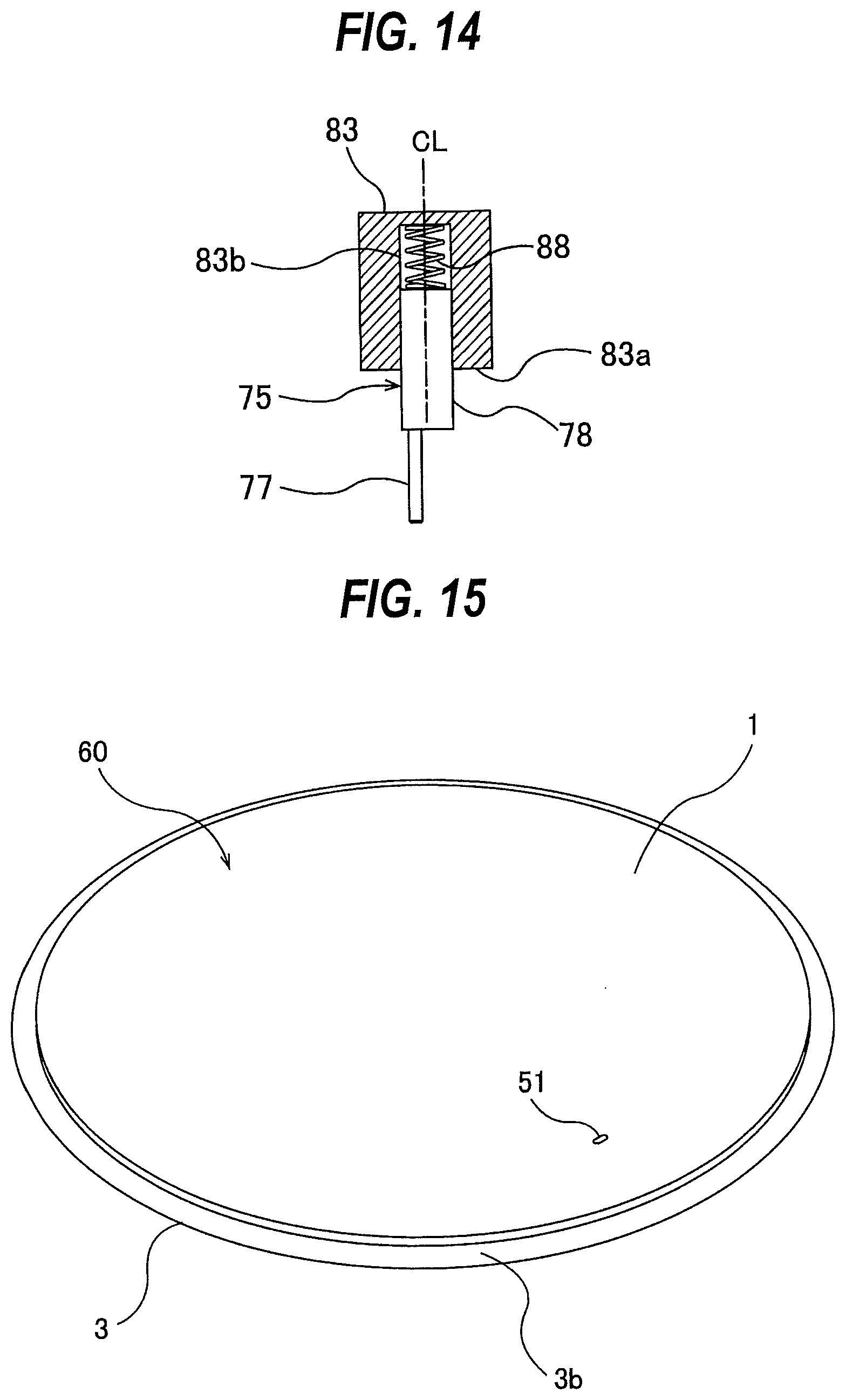
D00013
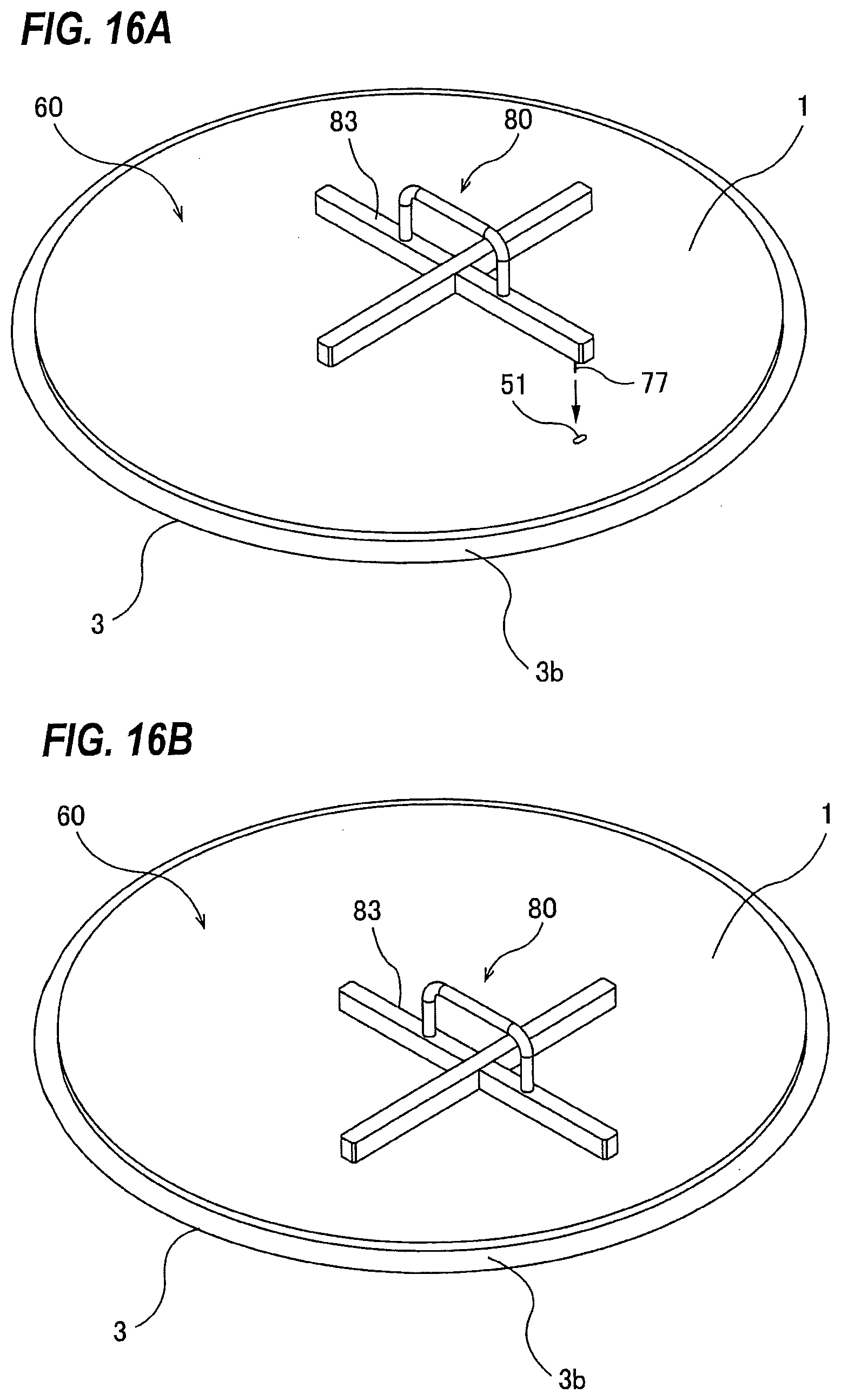
D00014
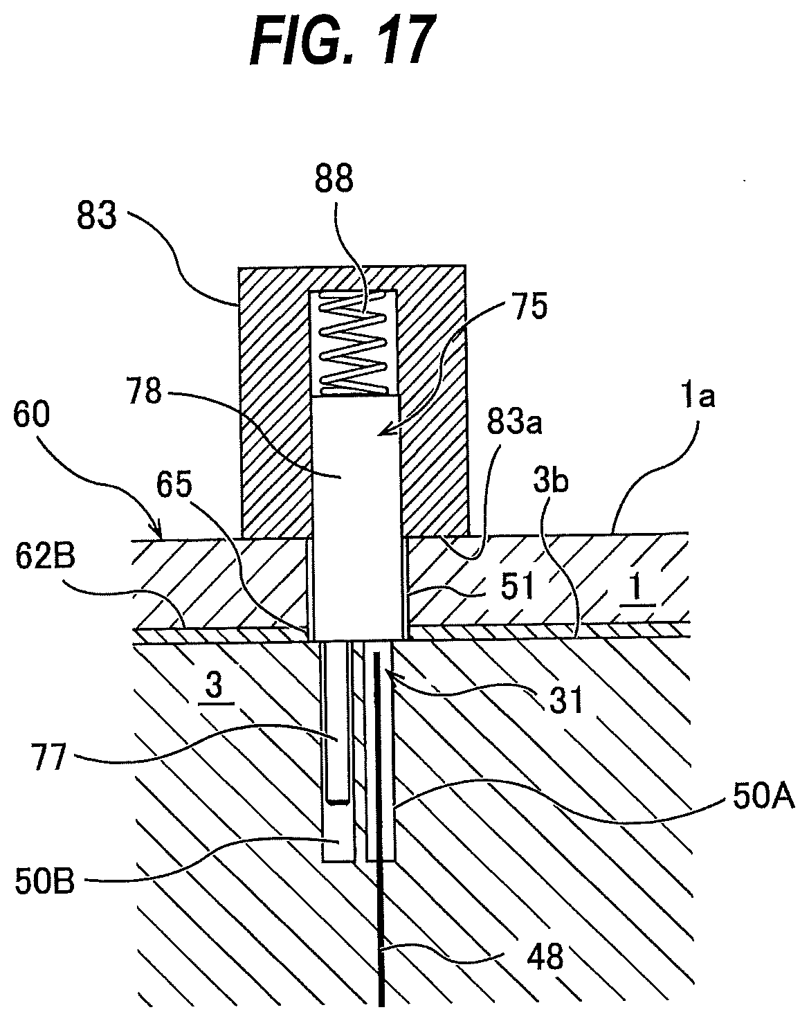
D00015
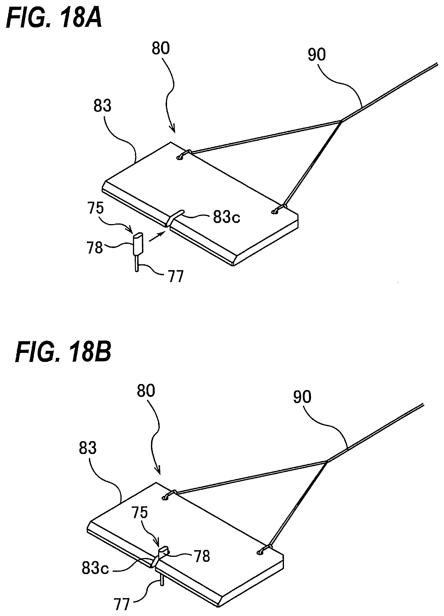
D00016
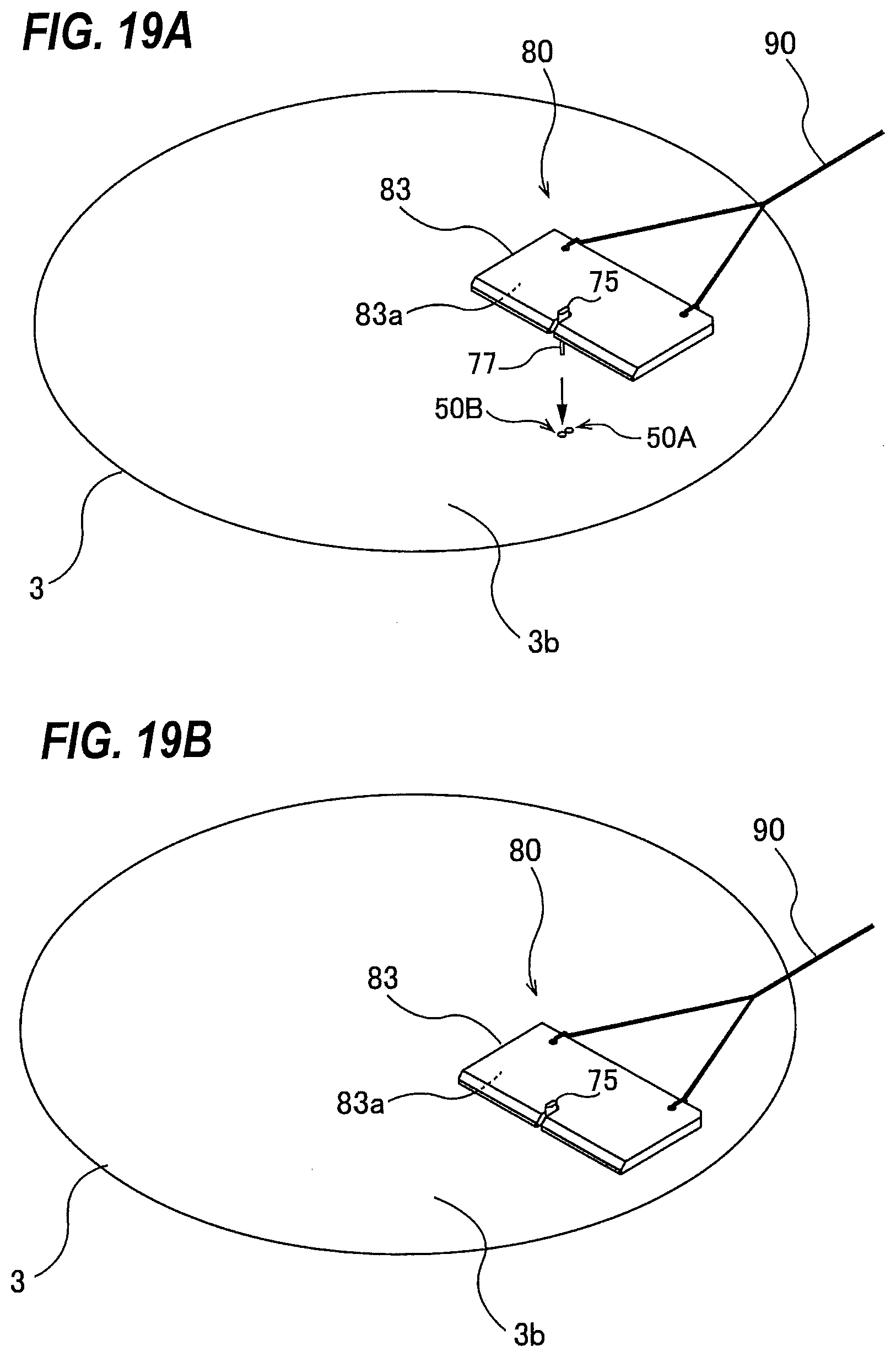
D00017
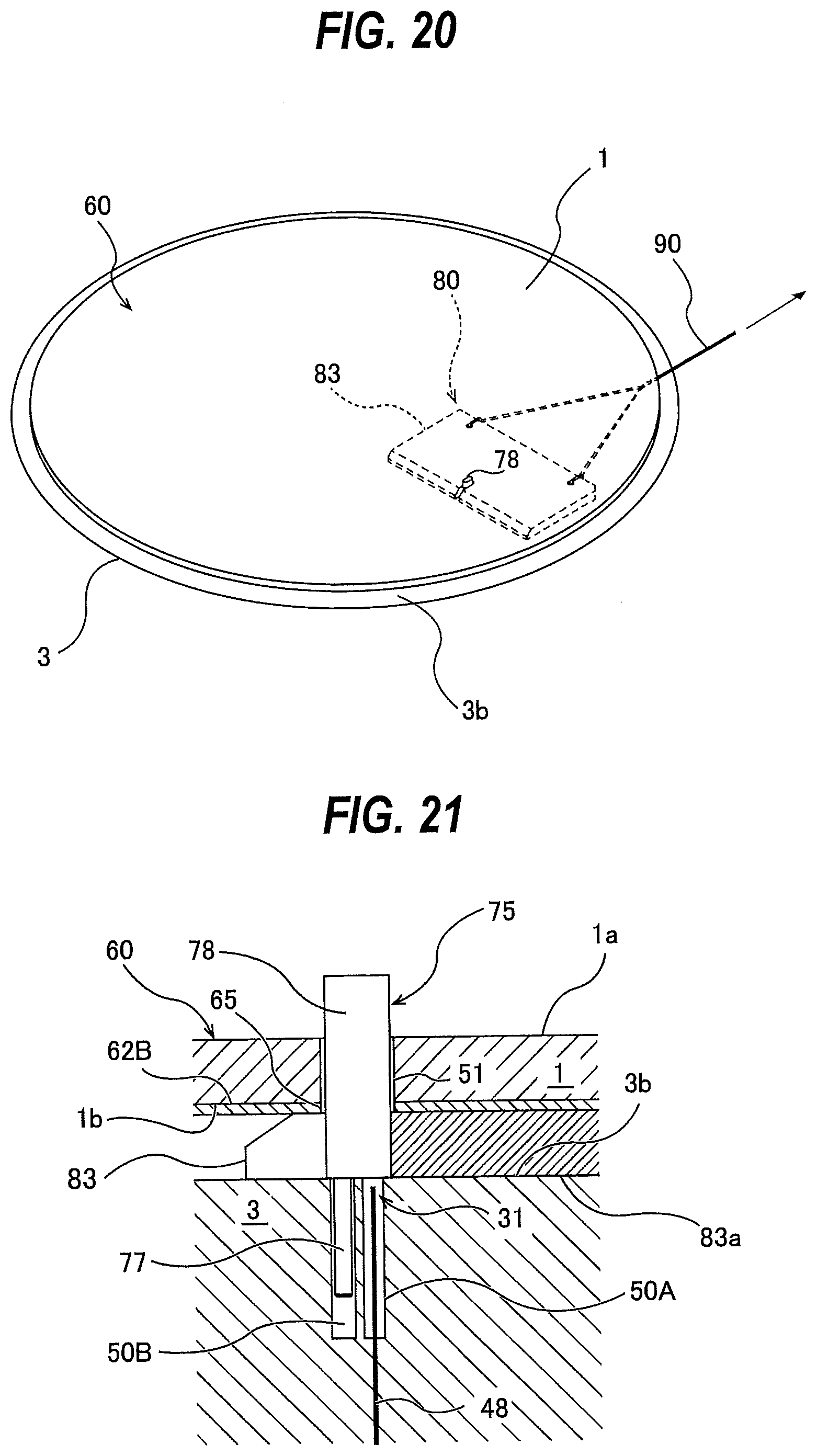
D00018
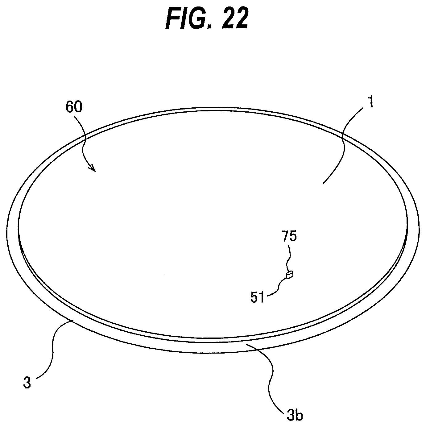
D00019
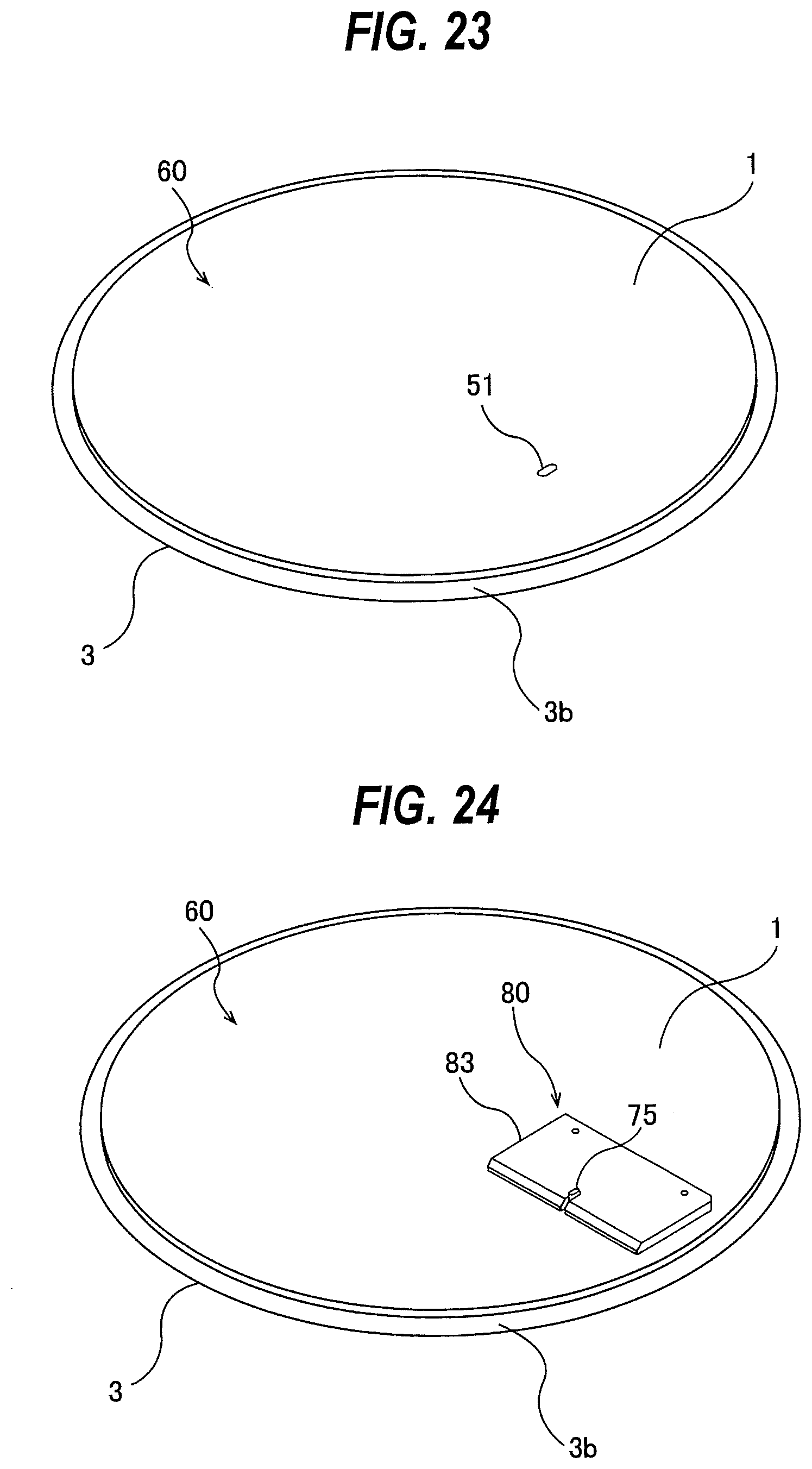
D00020
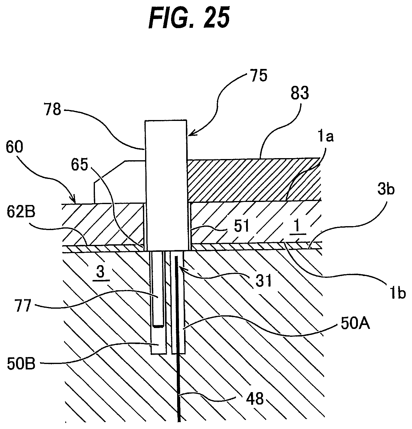
D00021
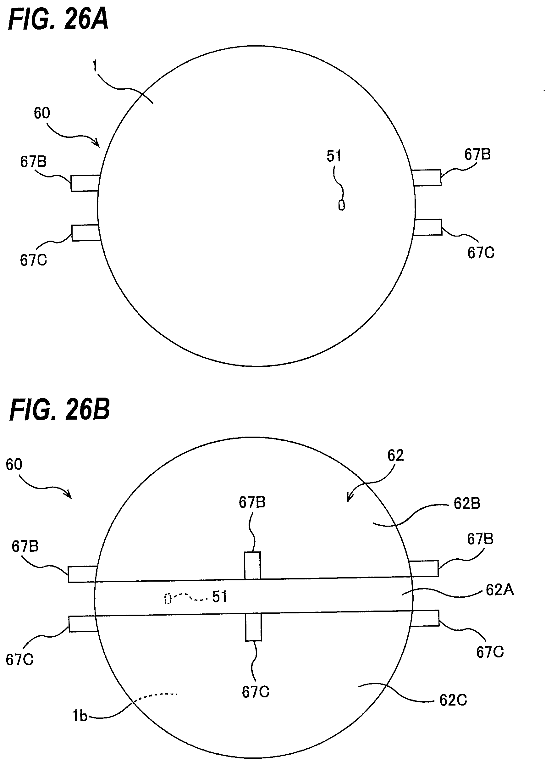
D00022
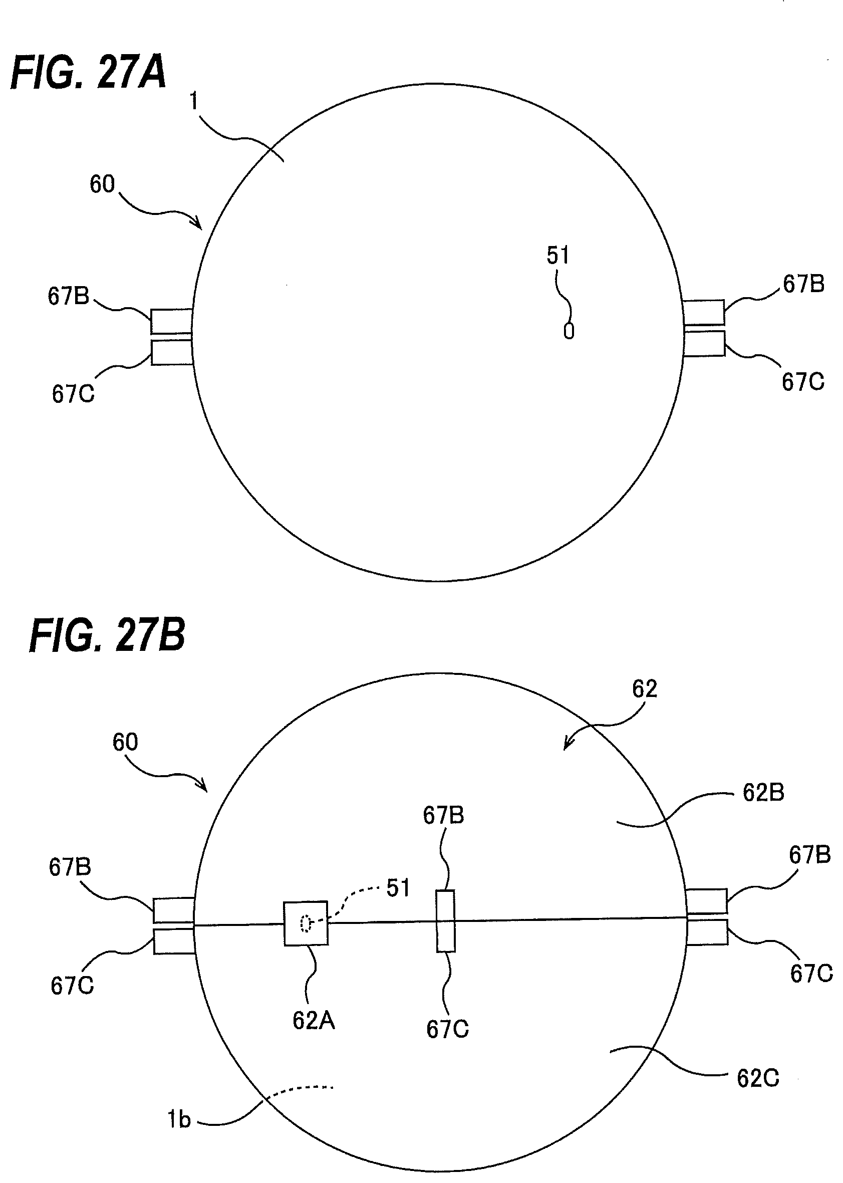
D00023
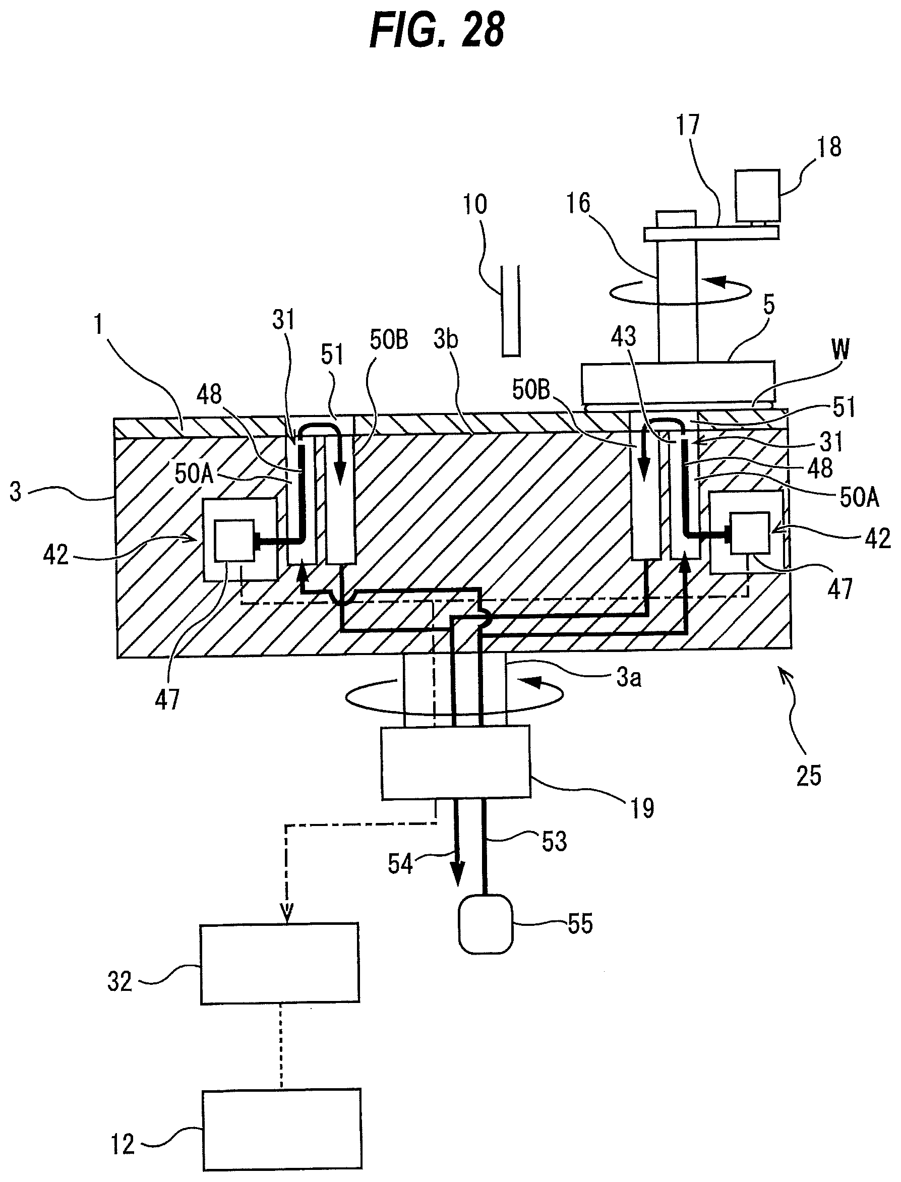
D00024
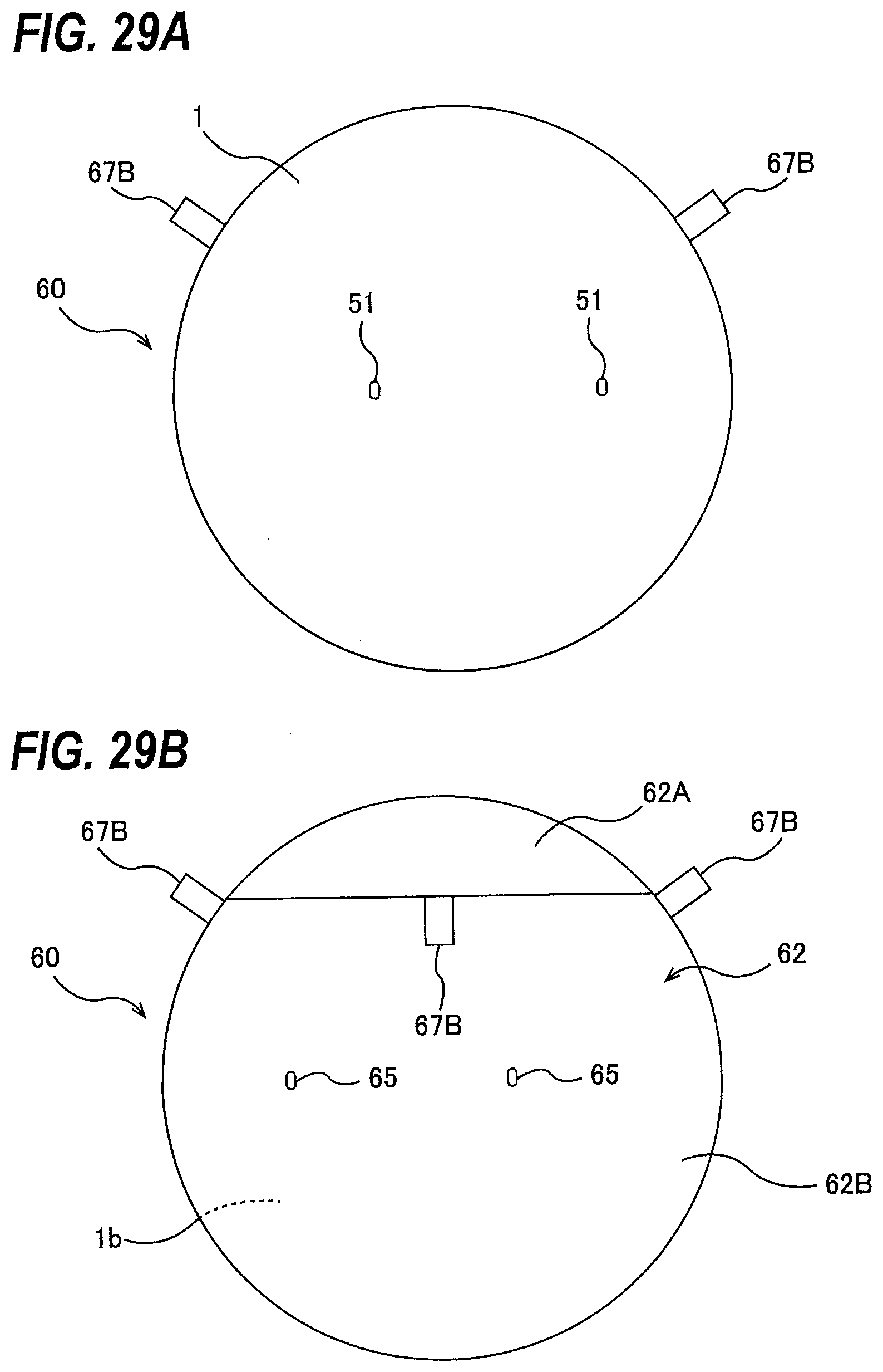
D00025
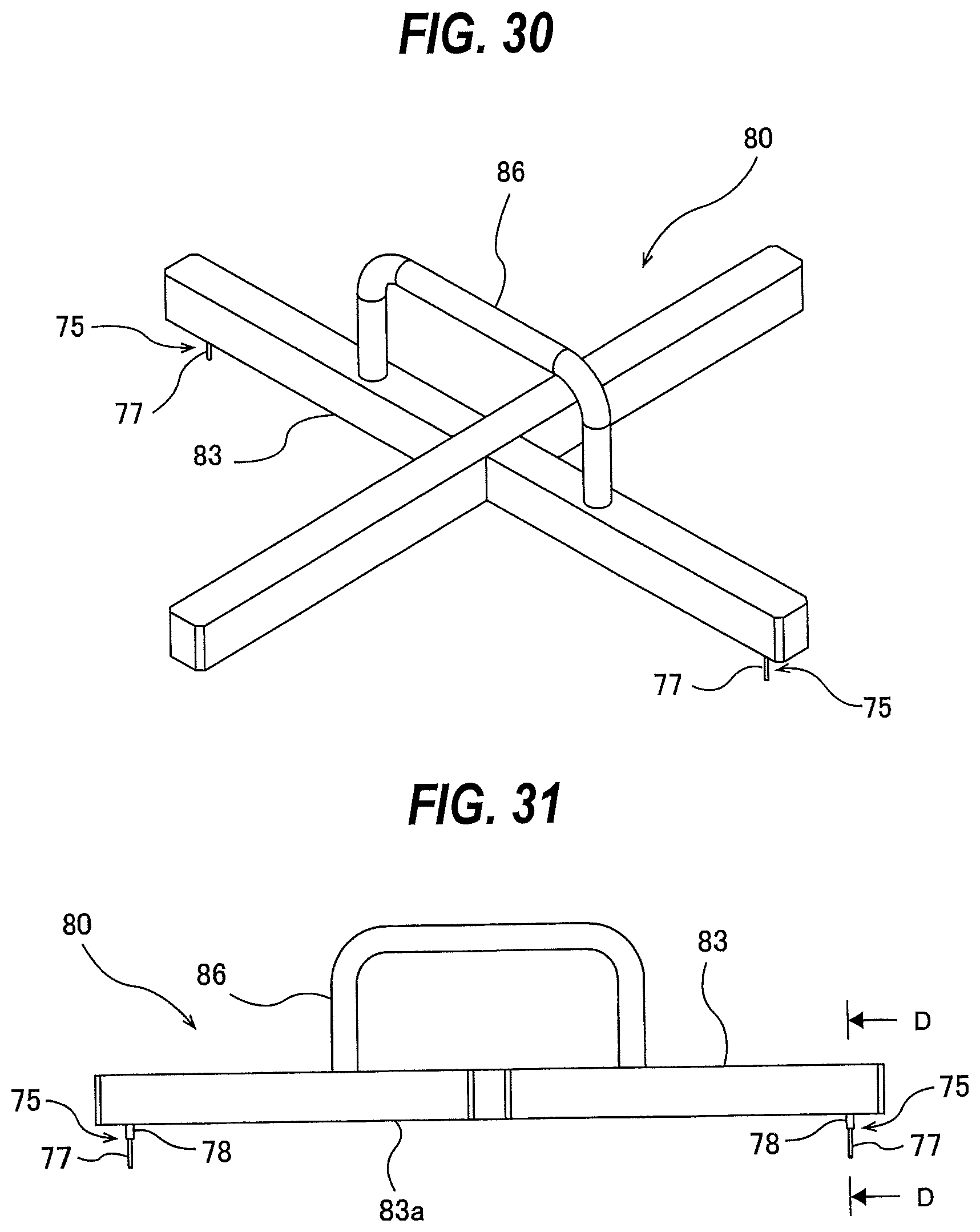
D00026
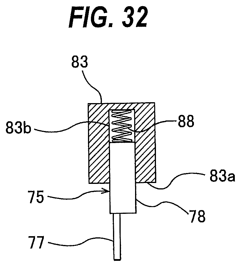
D00027
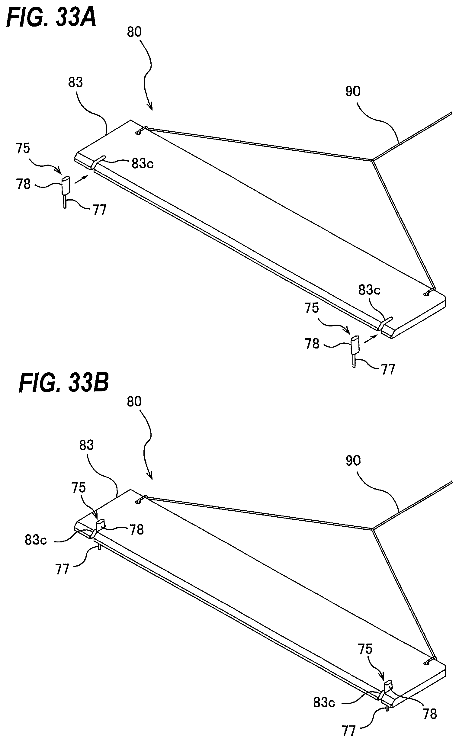
D00028
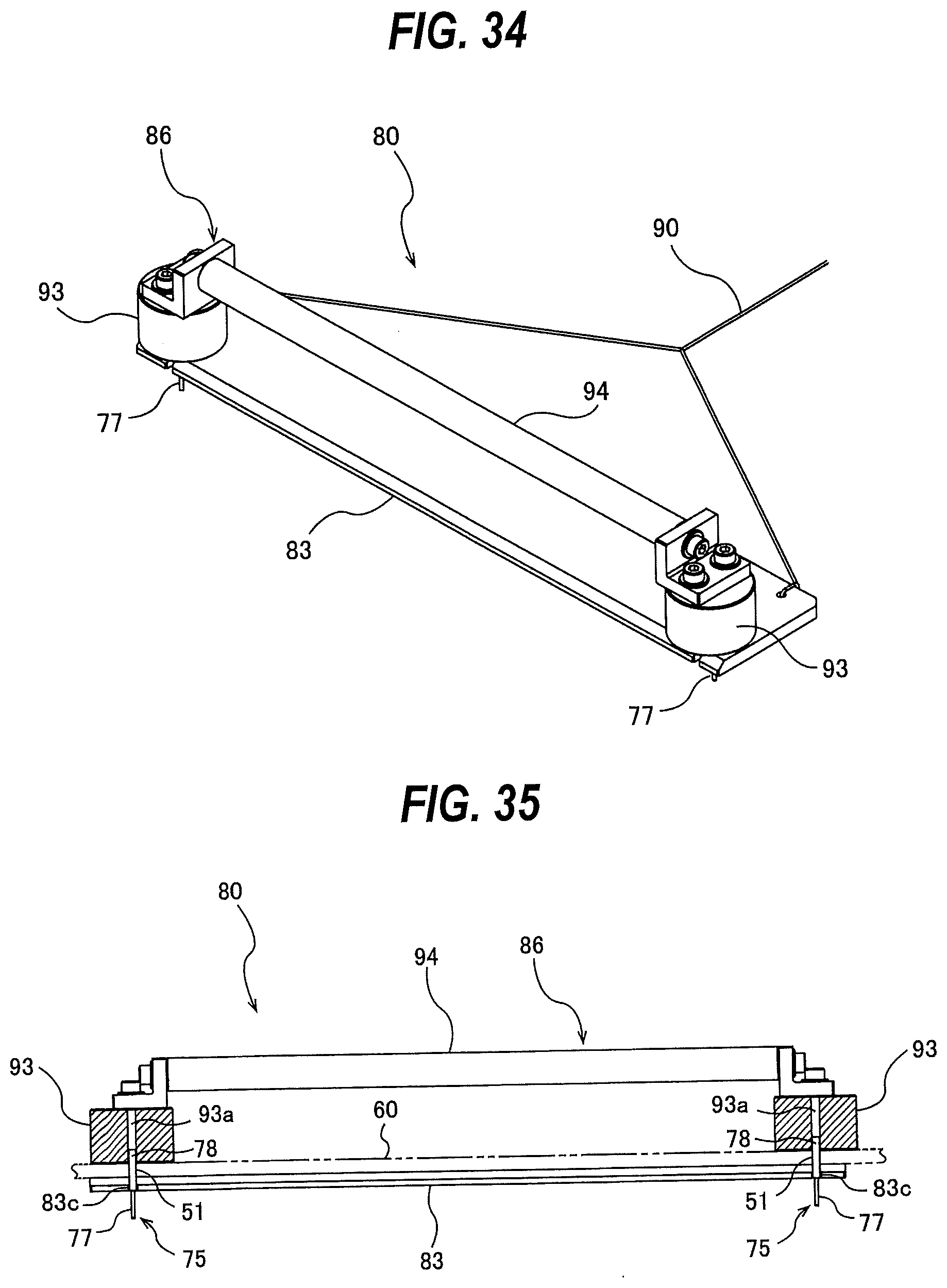
D00029
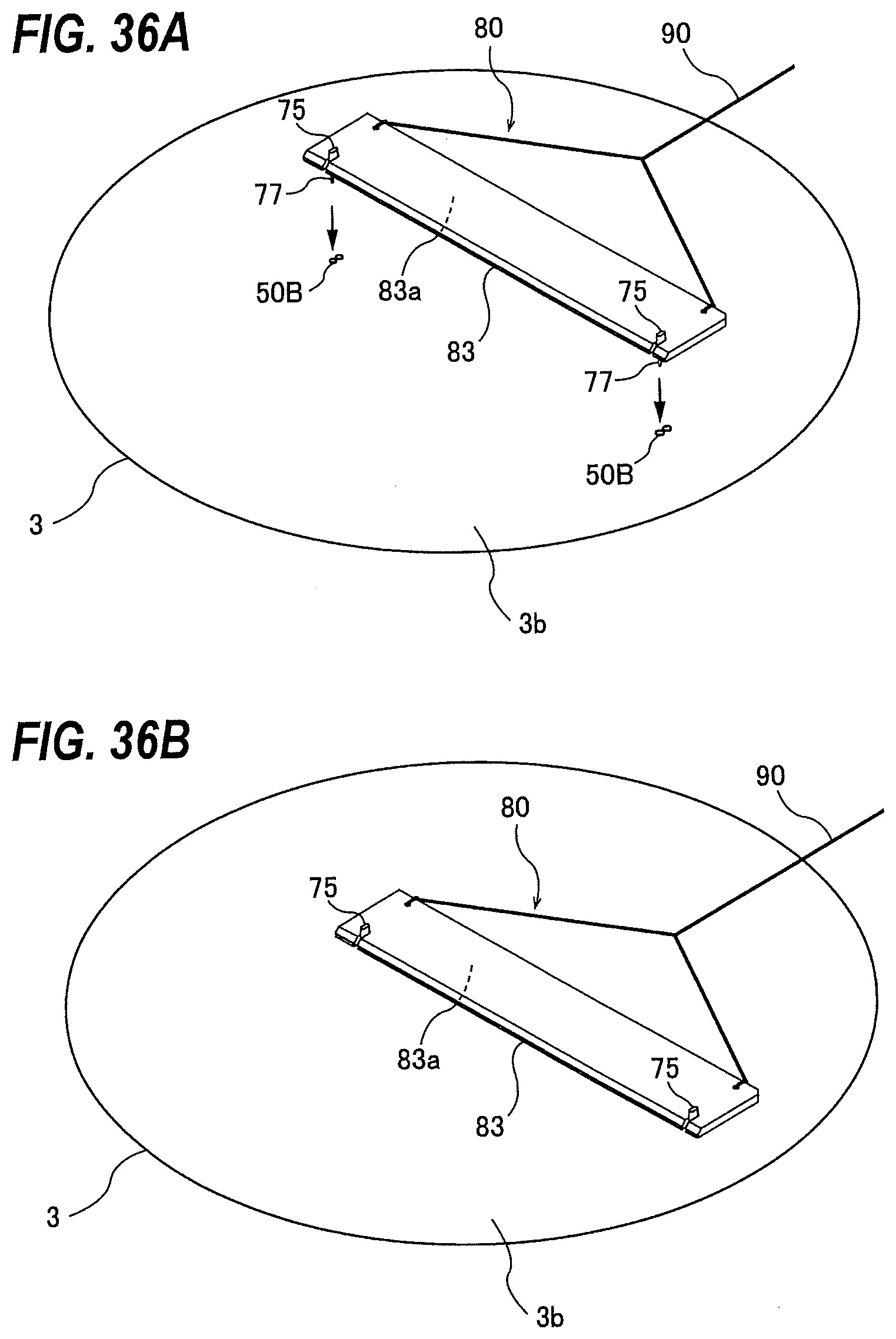
D00030
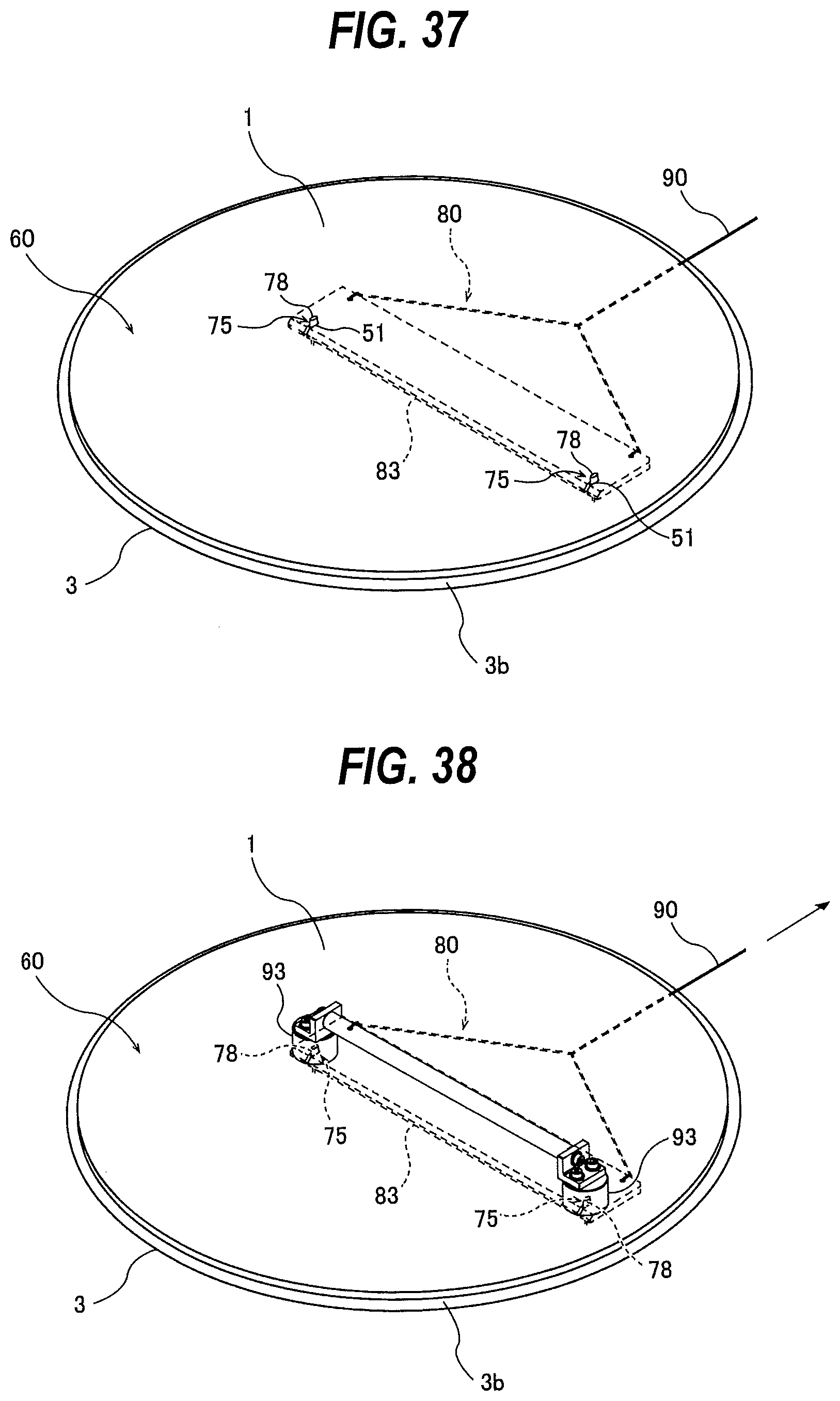
D00031
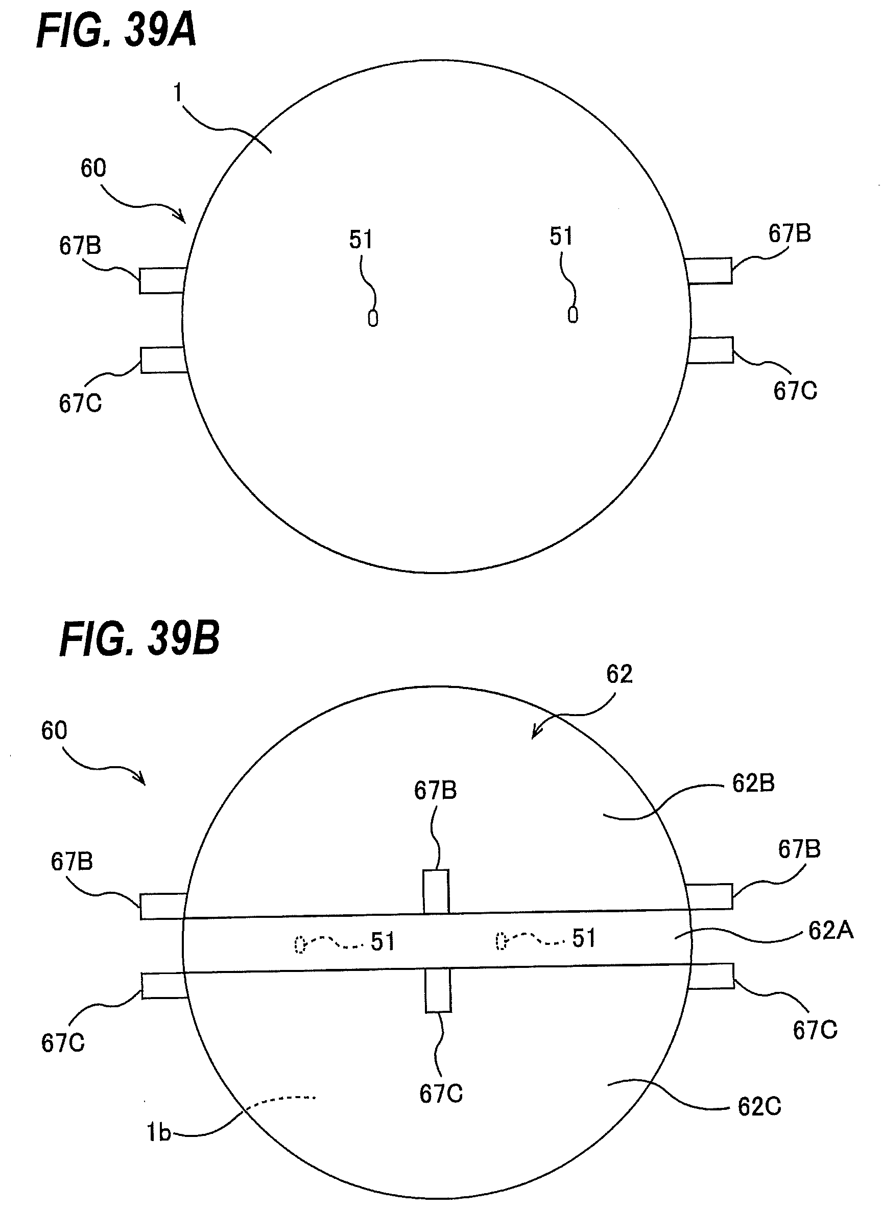
D00032
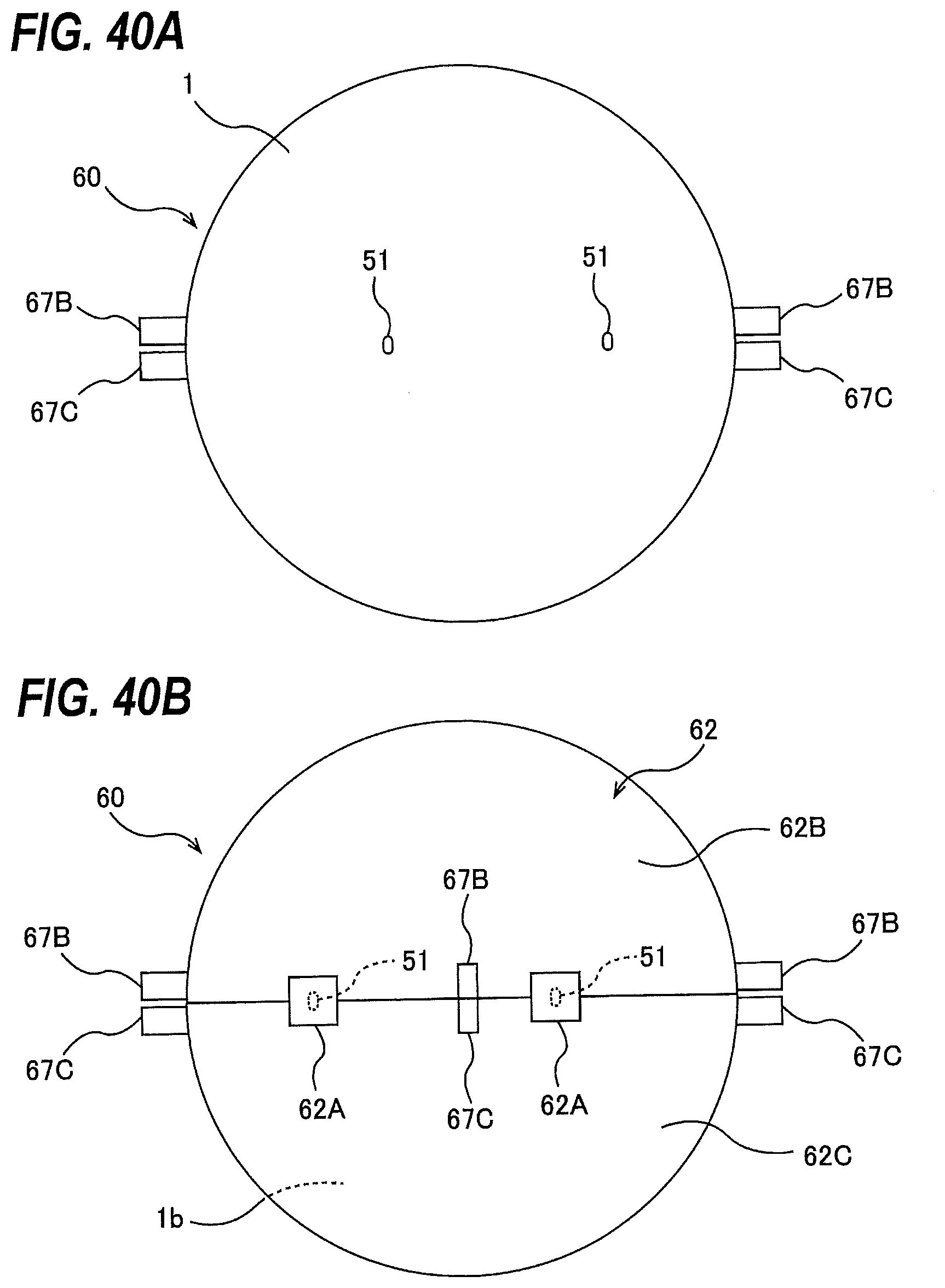
D00033
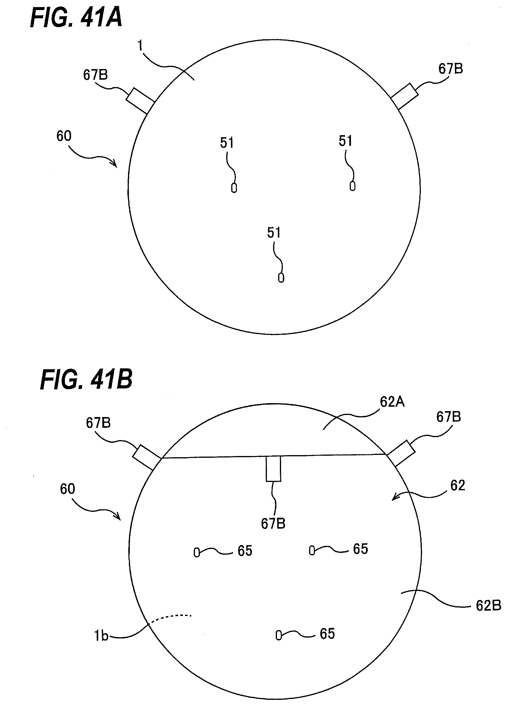
D00034
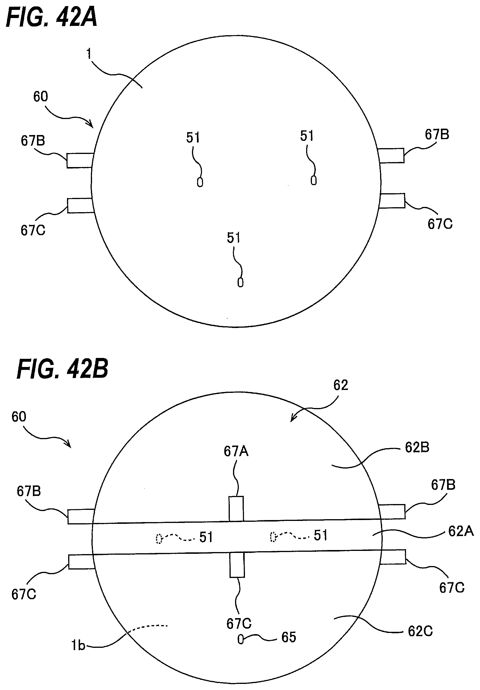
D00035
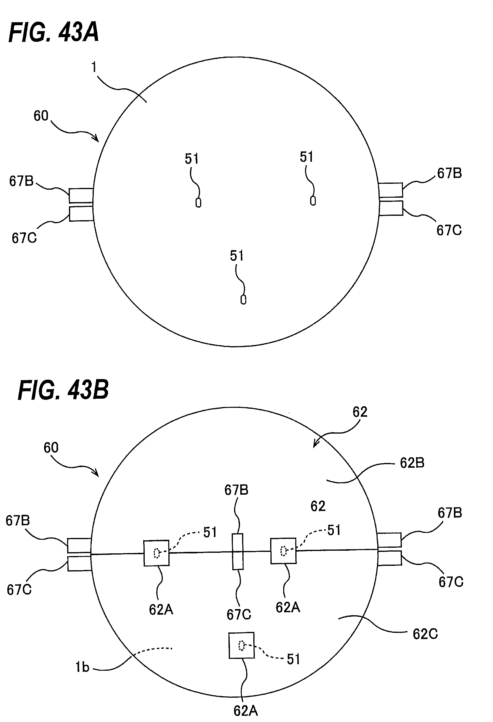
D00036
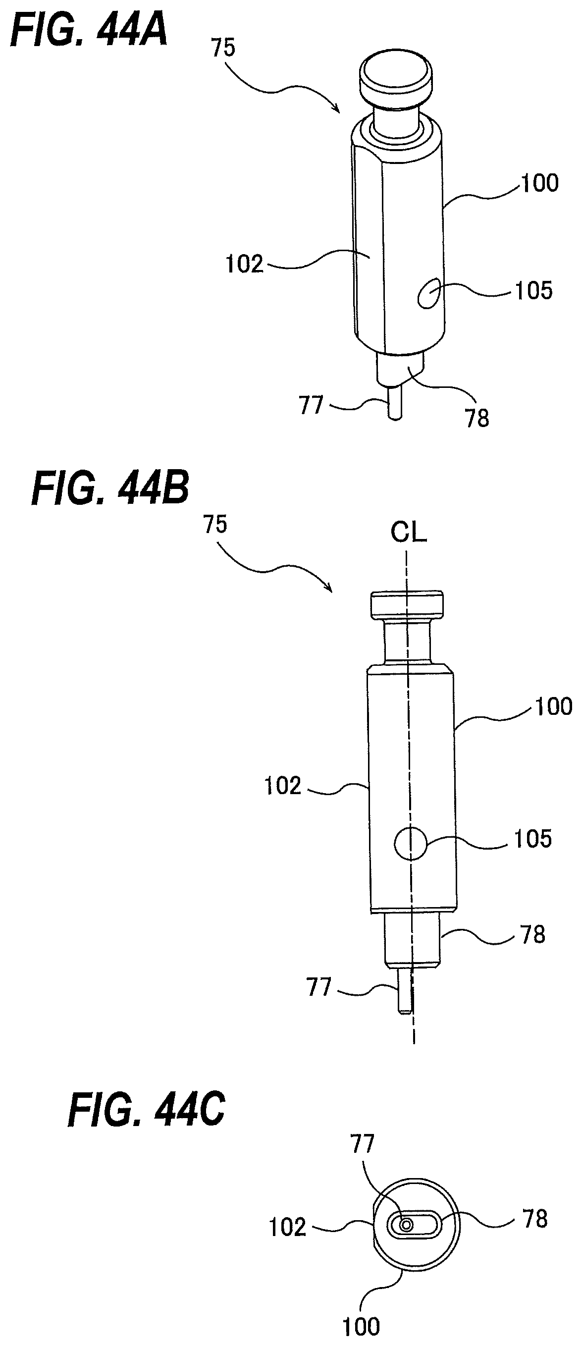
D00037
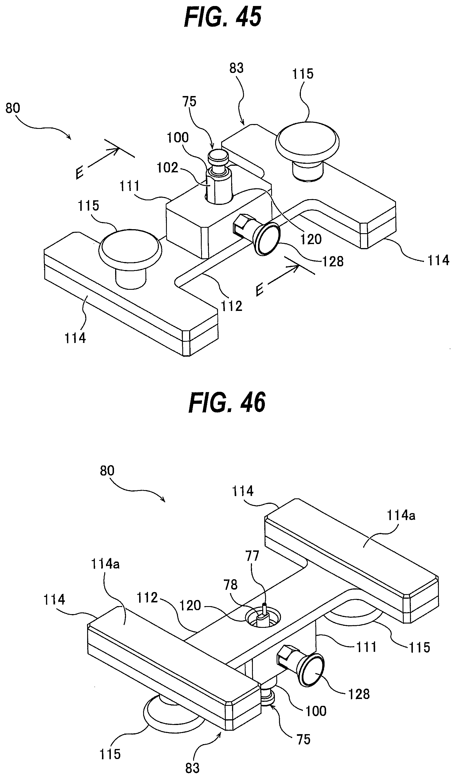
D00038
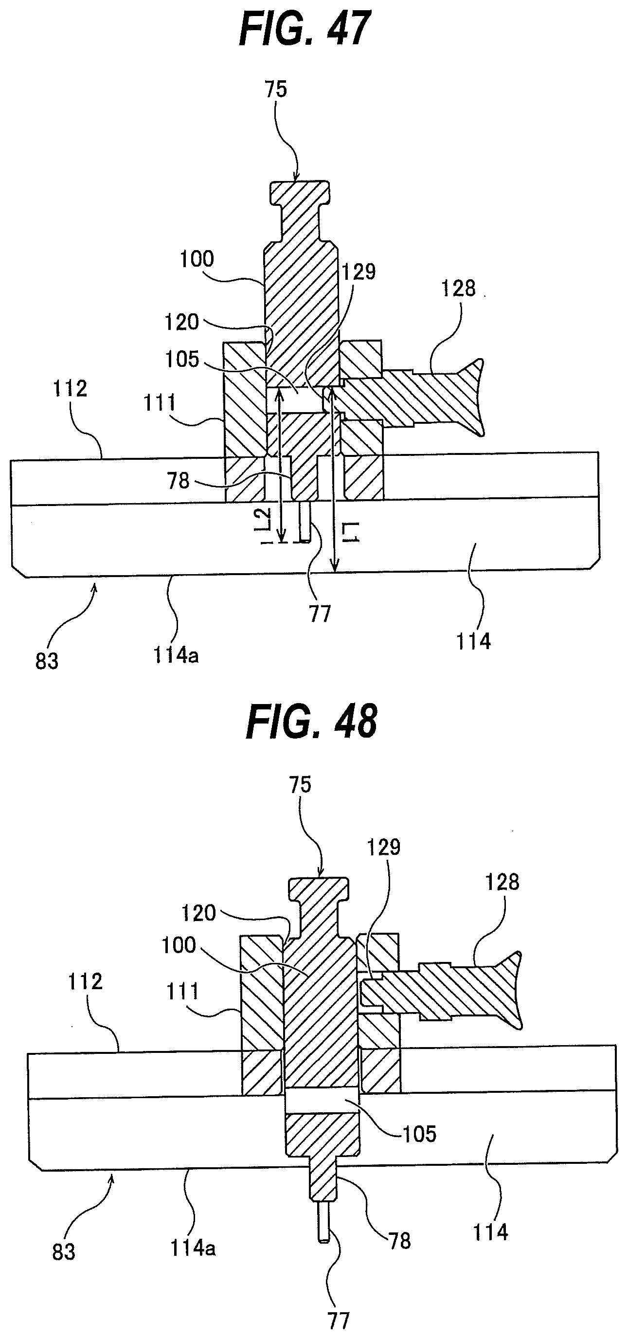
D00039
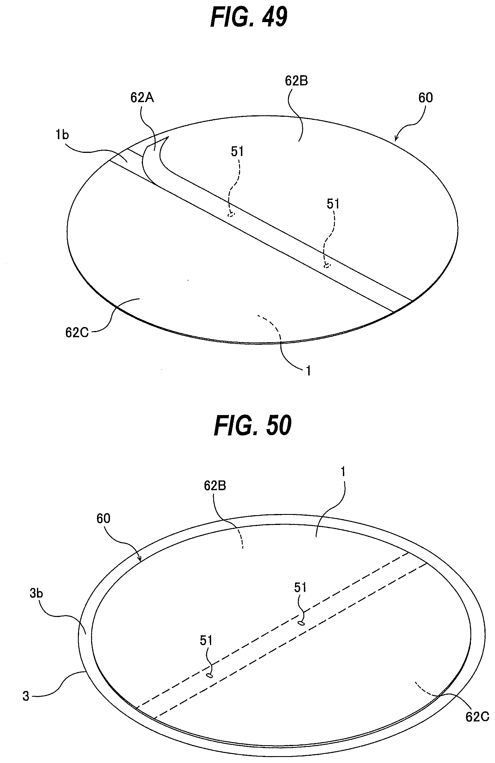
D00040
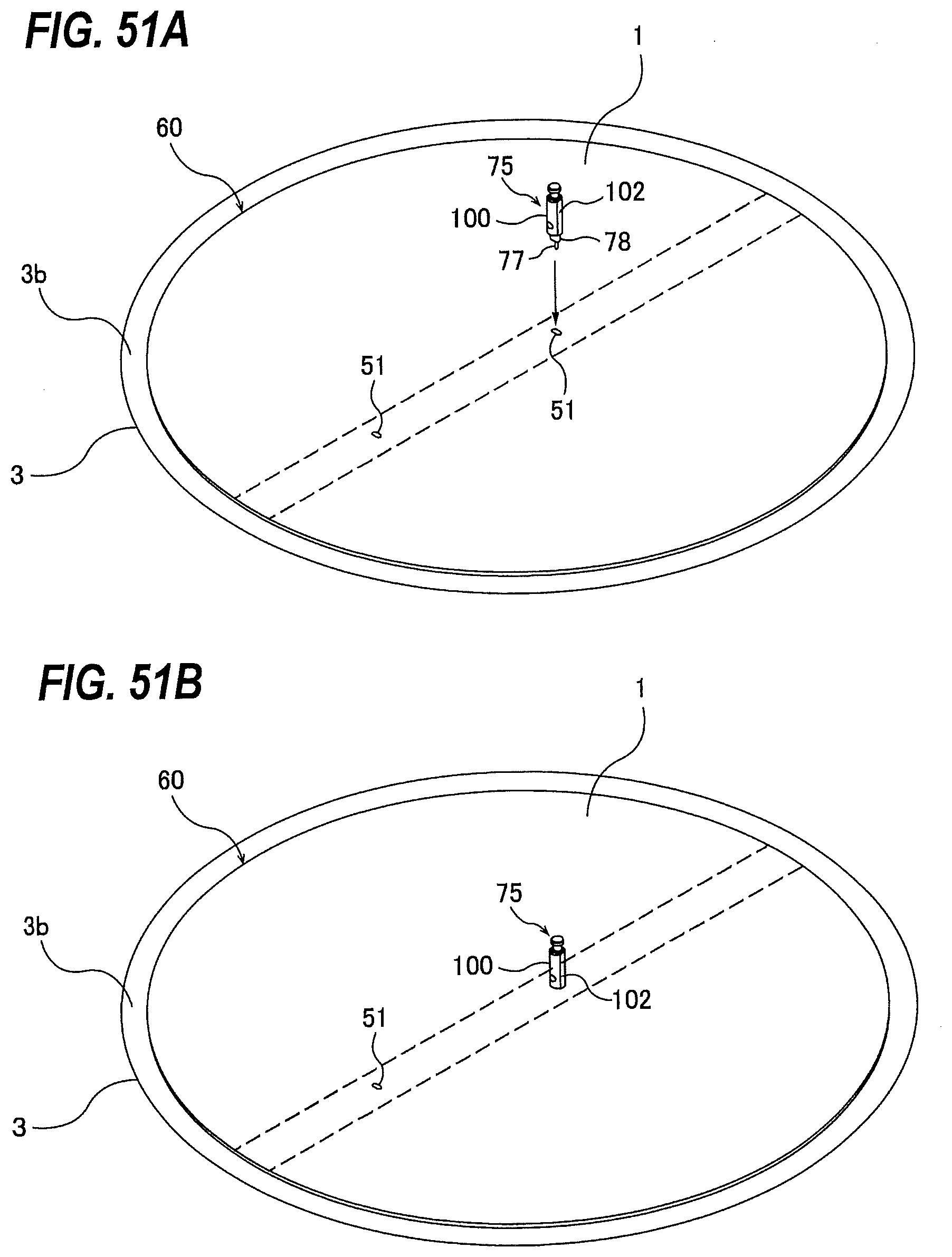
D00041
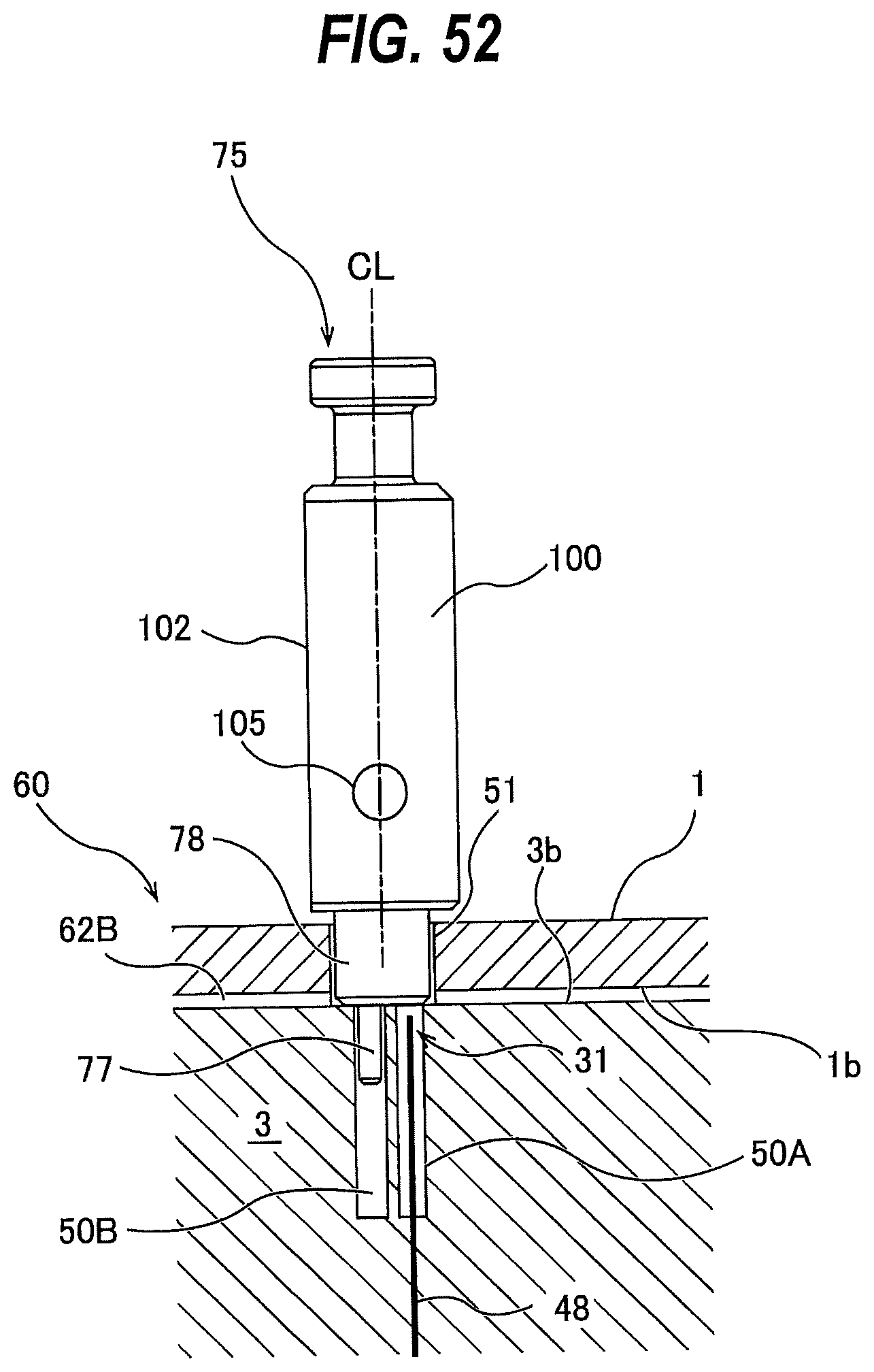
D00042
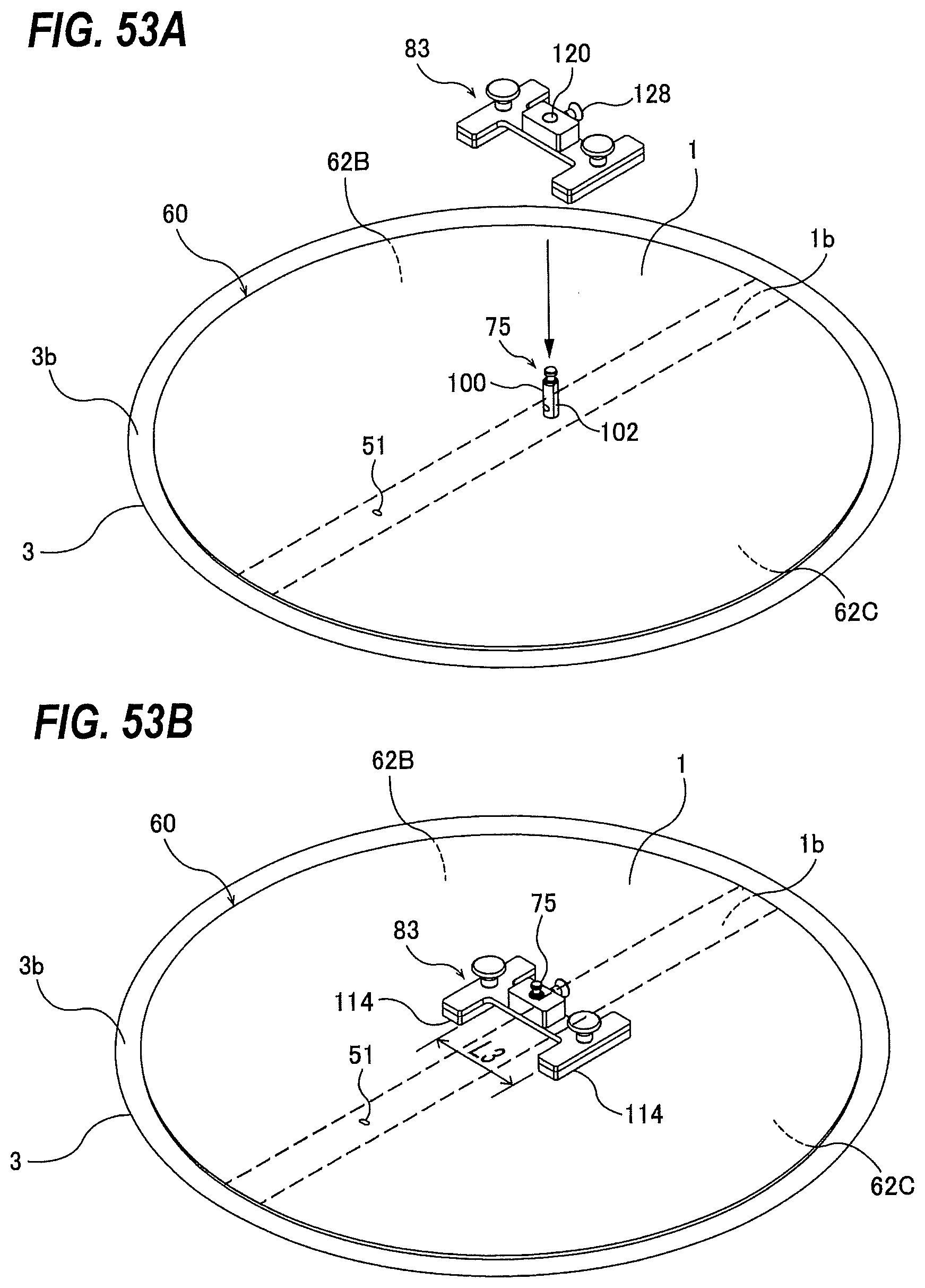
D00043
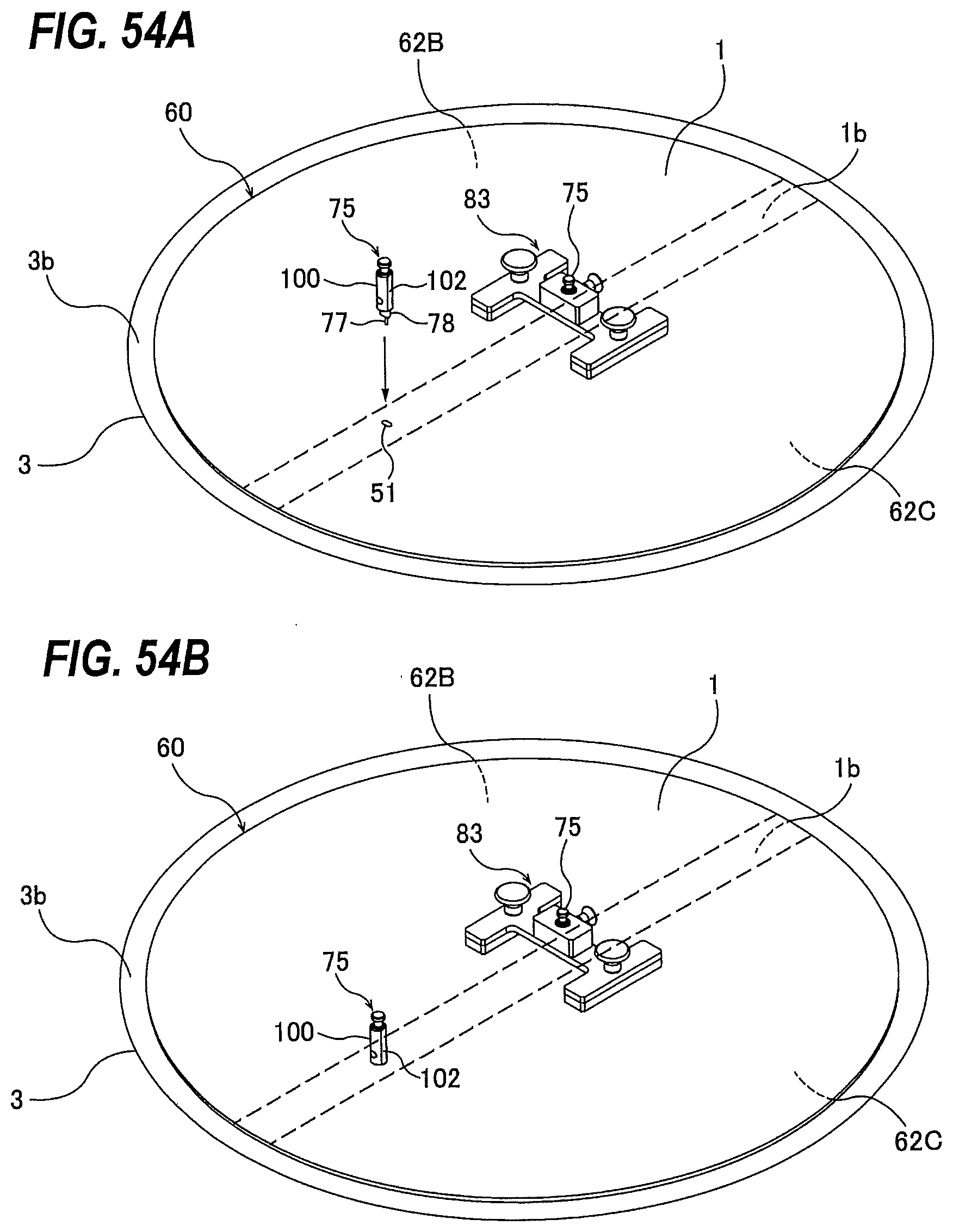
D00044
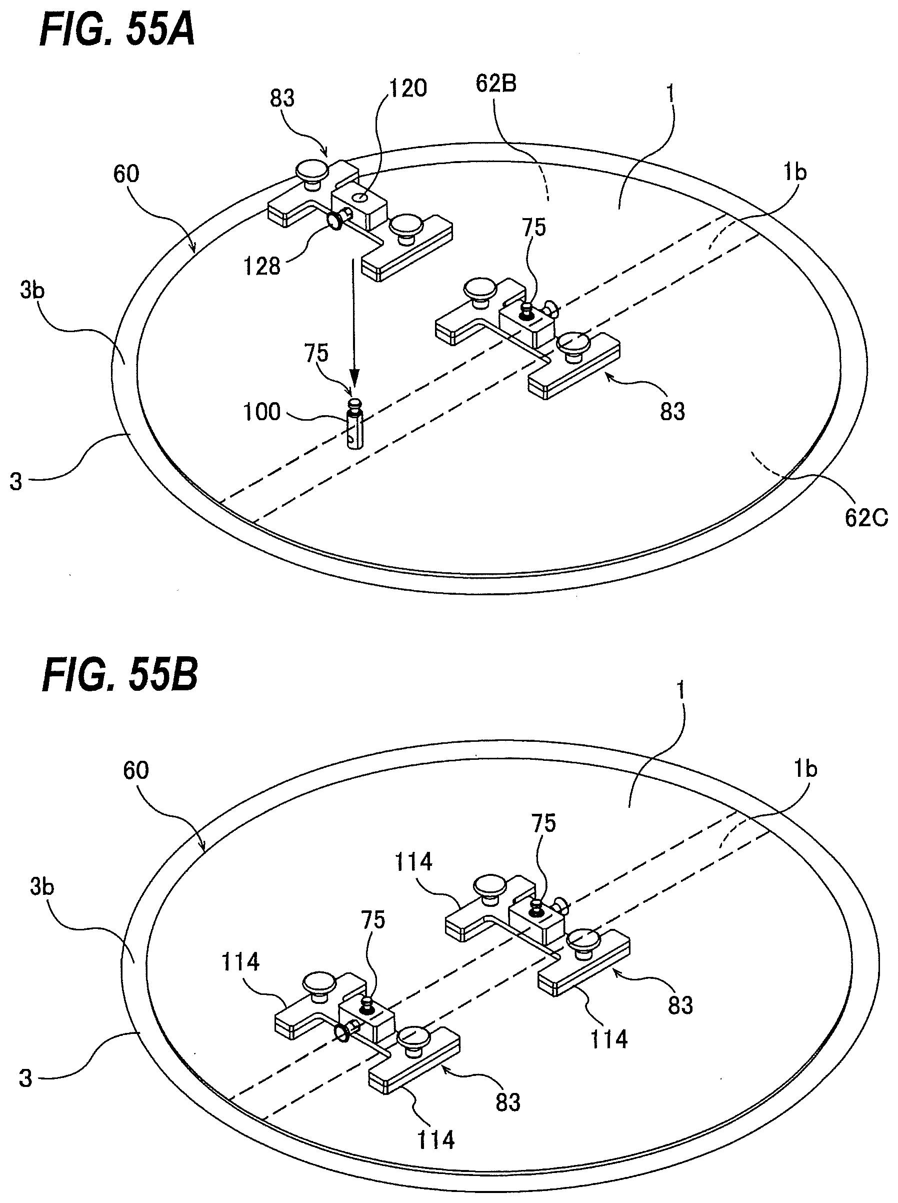
D00045
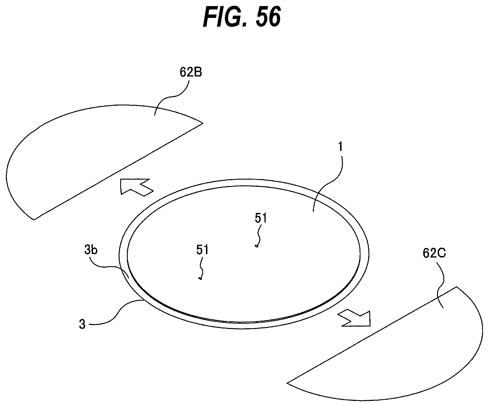
D00046
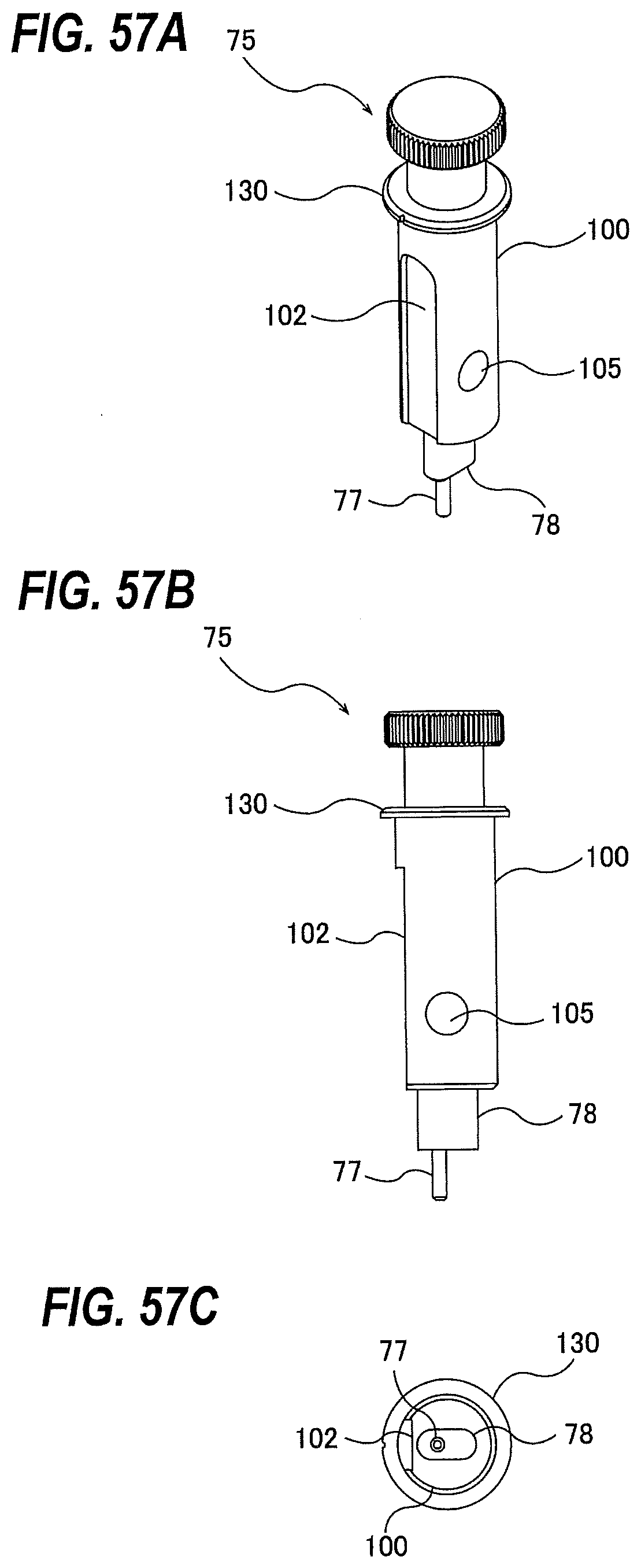
D00047
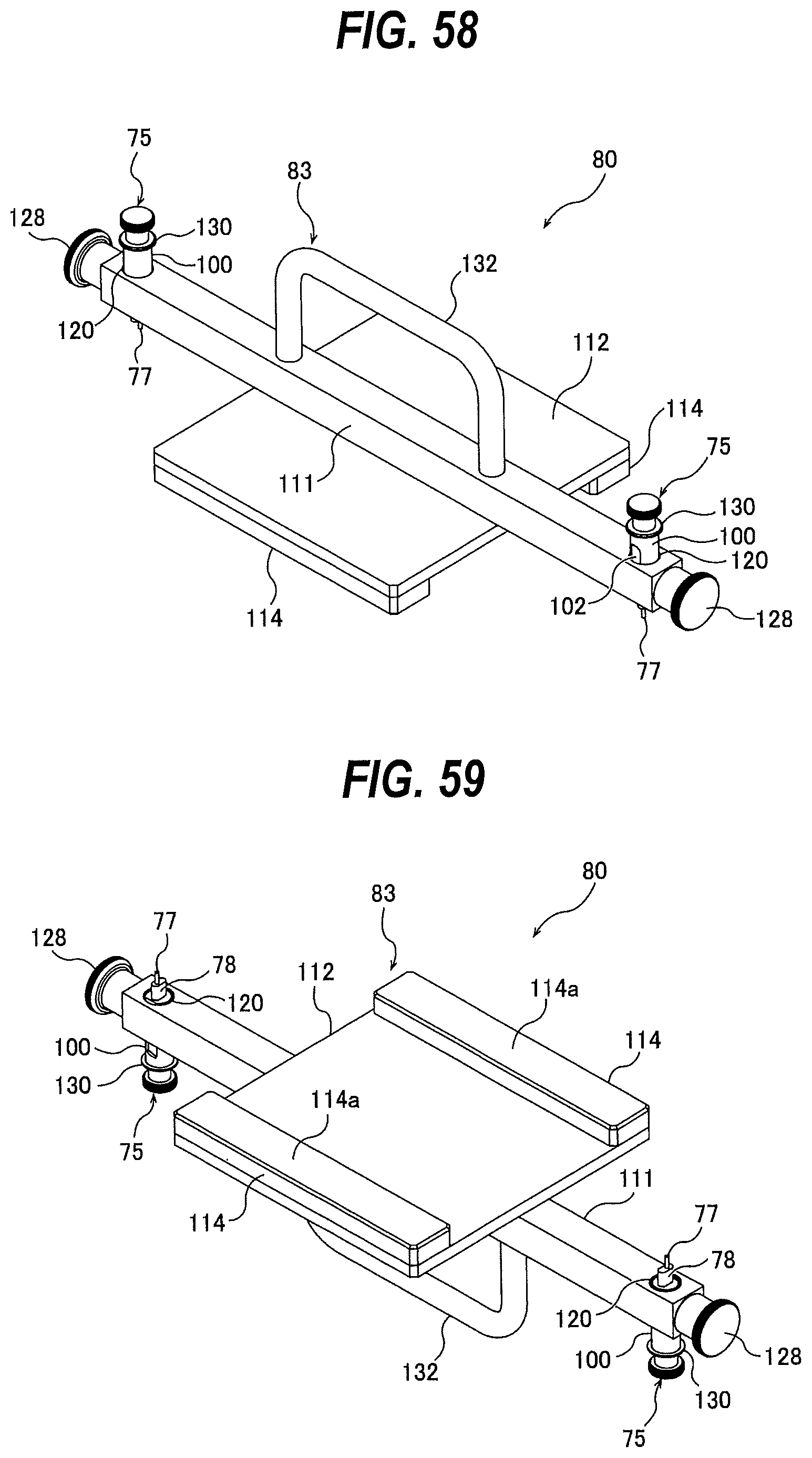
D00048
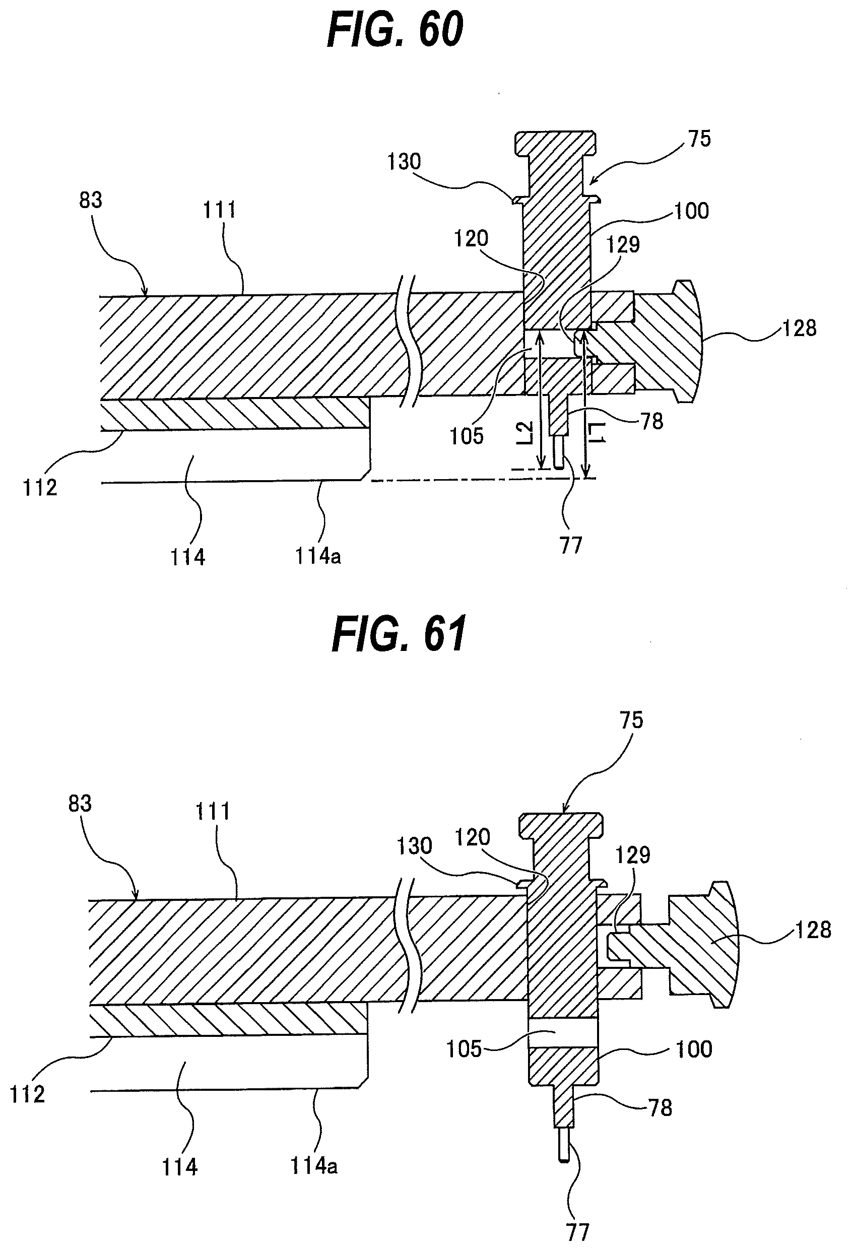
D00049
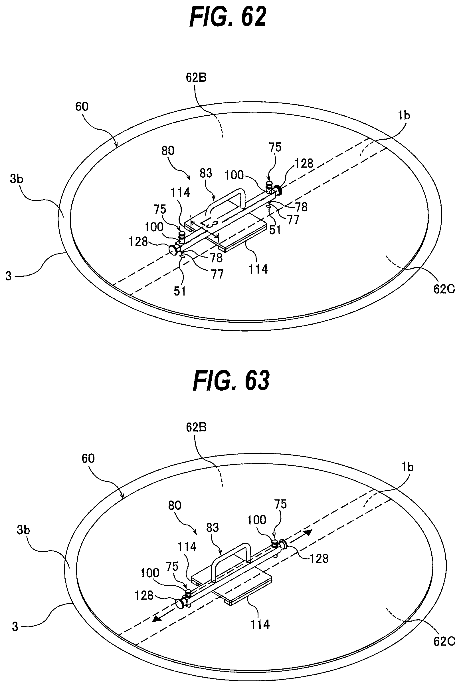
D00050
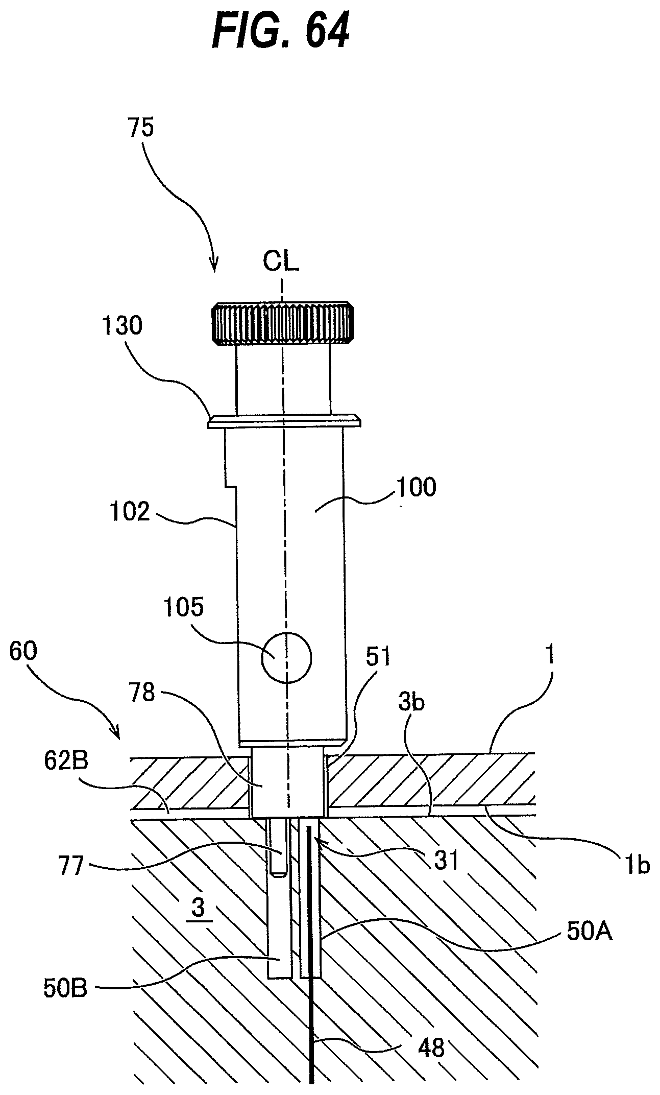
D00051
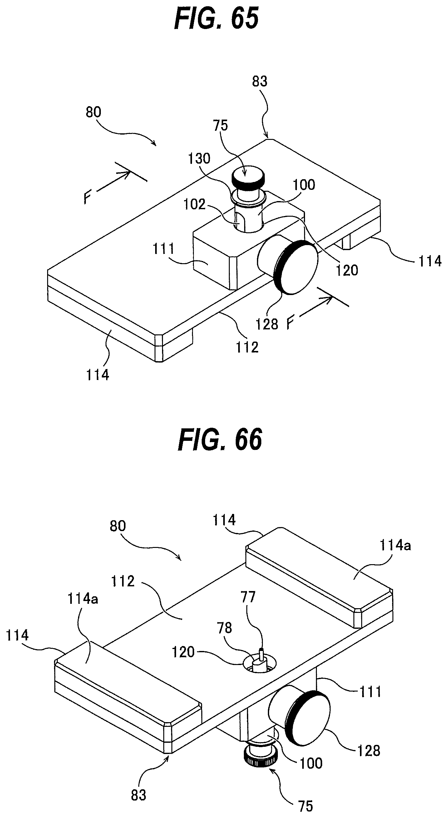
D00052
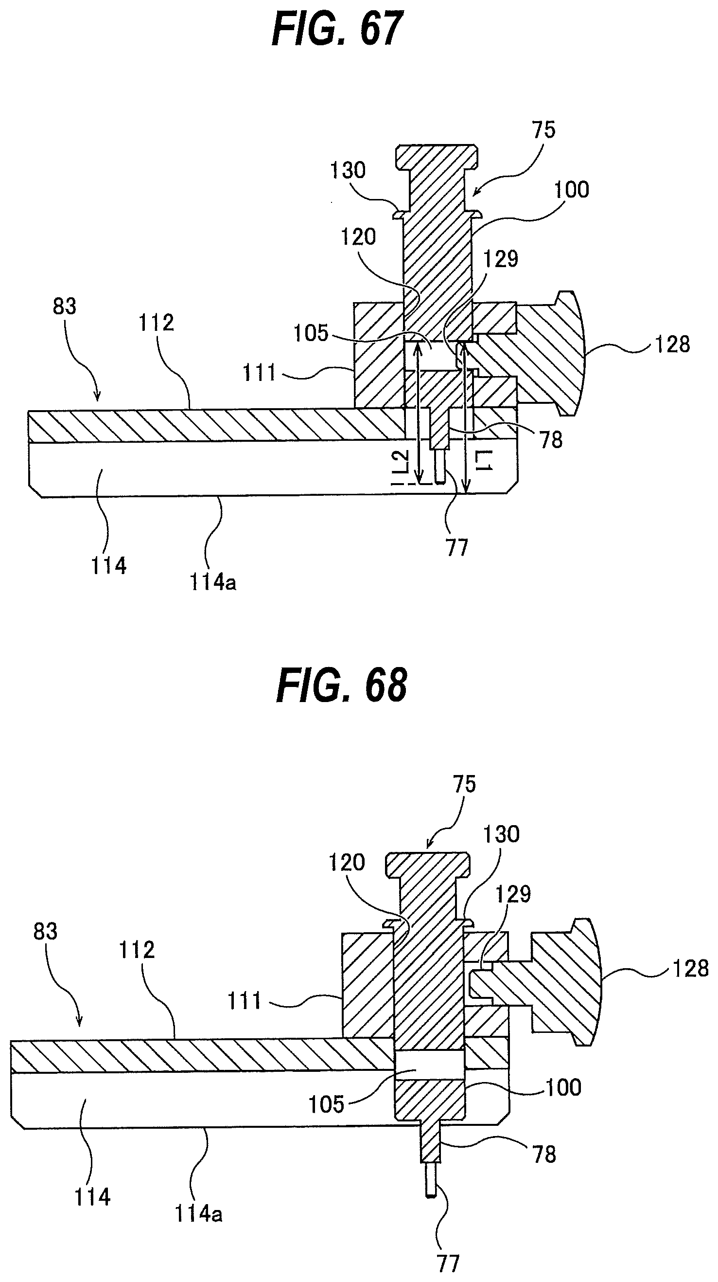
D00053
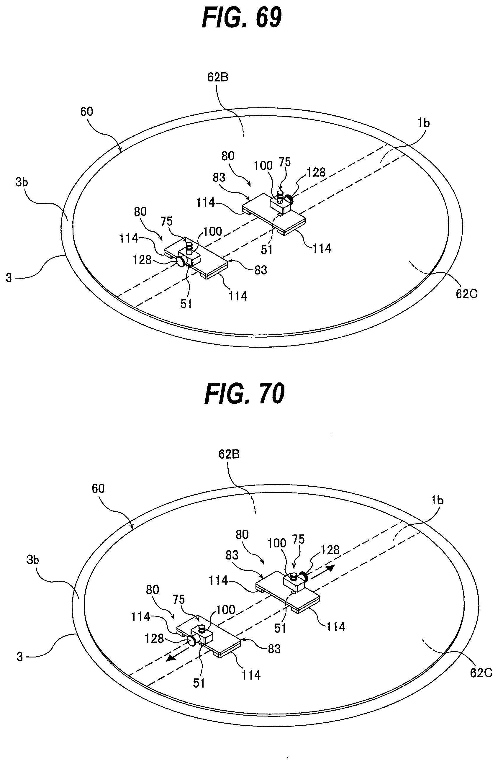
D00054
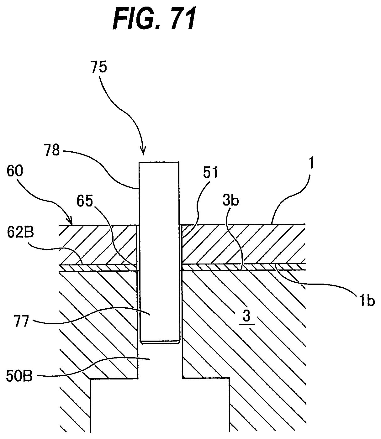
XML
uspto.report is an independent third-party trademark research tool that is not affiliated, endorsed, or sponsored by the United States Patent and Trademark Office (USPTO) or any other governmental organization. The information provided by uspto.report is based on publicly available data at the time of writing and is intended for informational purposes only.
While we strive to provide accurate and up-to-date information, we do not guarantee the accuracy, completeness, reliability, or suitability of the information displayed on this site. The use of this site is at your own risk. Any reliance you place on such information is therefore strictly at your own risk.
All official trademark data, including owner information, should be verified by visiting the official USPTO website at www.uspto.gov. This site is not intended to replace professional legal advice and should not be used as a substitute for consulting with a legal professional who is knowledgeable about trademark law.