Nozzle Device And Nozzle Unit
FUKAYA; Shinji ; et al.
U.S. patent application number 16/488877 was filed with the patent office on 2020-01-23 for nozzle device and nozzle unit. This patent application is currently assigned to Ihara Science Corporation. The applicant listed for this patent is Ihara Science Corporation. Invention is credited to Shinji FUKAYA, Hideichi TSUBOI.
| Application Number | 20200023400 16/488877 |
| Document ID | / |
| Family ID | 63254225 |
| Filed Date | 2020-01-23 |


View All Diagrams
| United States Patent Application | 20200023400 |
| Kind Code | A1 |
| FUKAYA; Shinji ; et al. | January 23, 2020 |
NOZZLE DEVICE AND NOZZLE UNIT
Abstract
In order to enable the outflow direction of a fluid to be changed and to enable the outflow position of the fluid to be freely set, a nozzle device (7) of the present invention comprising: a flow path body that flows or holds a fluid and that has a flow path wall (6); and a nozzle unit (1) including a nozzle body (3) having a spherical surface on an outer periphery thereof and having a fluid passage (3a) formed thereinside, a holding mechanism of the nozzle body (3), and a securing member (4) that fixes the holding mechanism to the flow path wall (6), wherein the holding mechanism is made of a pair of thin plate members (2), each having a contact holding portion (2b) in contact with the spherical surface of the nozzle body (3) and having a flat portion (2a), and the holding mechanism rotatably holds the spherical surface in a state in which the nozzle body (3) is sandwiched by the contact holding portions (2b) of a pair of the thin plate members (2).
| Inventors: | FUKAYA; Shinji; (Minato-ku, Tokyo, JP) ; TSUBOI; Hideichi; (Minato-ku, Tokyo, JP) | ||||||||||
| Applicant: |
|
||||||||||
|---|---|---|---|---|---|---|---|---|---|---|---|
| Assignee: | Ihara Science Corporation Minato-Ku, TokyoV JP |
||||||||||
| Family ID: | 63254225 | ||||||||||
| Appl. No.: | 16/488877 | ||||||||||
| Filed: | February 21, 2018 | ||||||||||
| PCT Filed: | February 21, 2018 | ||||||||||
| PCT NO: | PCT/JP2018/006224 | ||||||||||
| 371 Date: | August 26, 2019 |
| Current U.S. Class: | 1/1 |
| Current CPC Class: | B05B 15/652 20180201; B05B 1/202 20130101; F16J 15/0818 20130101; F16J 15/10 20130101; B05B 15/654 20180201; B23Q 11/10 20130101 |
| International Class: | B05B 15/652 20060101 B05B015/652; B23Q 11/10 20060101 B23Q011/10 |
Foreign Application Data
| Date | Code | Application Number |
|---|---|---|
| Feb 27, 2017 | JP | 2017-035052 |
Claims
1. A nozzle device comprising: a flow path body that flows or holds a fluid and that has a flow path wall; and a nozzle unit including a nozzle body having a spherical surface on an outer periphery thereof and having a fluid passage formed thereinside, a holding mechanism of said nozzle body, and a securing member that fixes said holding mechanism to said flow path wall, wherein said holding mechanism is made of a pair of thin plate members, each having a contact holding portion in contact with said spherical surface of said nozzle body and having a flat portion, and said holding mechanism rotatably holds said spherical surface in a state in which said nozzle body is sandwiched by said contact holding portions of a pair of said thin plate members.
2. The nozzle device according to claim 1, wherein said contact holding portion has a shape bent from said flat portion, the shape having a hollow portion that is tapered away from said flat portion.
3. The nozzle device according to claim 2, wherein said nozzle body is held in a holding space formed by connecting said hollow portions of said contact holding portions of a pair of said thin plate members.
4. The nozzle device according to claim 1, further comprising a gasket disposed between said thin plate member and said flow path wall.
5. The nozzle device according to claim 1, wherein said securing member is a screw fixed to said flow path wall.
6. The nozzle device according to claim 5, wherein the screw is a tapping screw.
7. The nozzle device according to claim 1, wherein said securing member is a rivet crimped to said flow path wall.
8. The nozzle device according to claim 1, wherein said nozzle body has a shape in which said fluid passage is formed into a through-hole shape in a spherical body.
9. The nozzle device according to claim 1, wherein a pipe member that becomes an extension portion of said fluid passage is attached to said fluid passage of said nozzle body.
10. The nozzle device according to claim 1, wherein said thin plate member is partially curved according to the shape of said flow path wall.
11. The nozzle device according to claim 1, wherein in a state in which said securing member fixes said holding mechanism to said flow path wall, said contact holding portions of a pair of said thin plate members press and hold said nozzle body therebetween.
12. The nozzle device according to claim 1, wherein said nozzle unit is attached to a surface facing inward of said flow path body of said flow path wall.
13. The nozzle device according to claim 1, wherein said flow path wall is attachable to and detachable from a main body portion of said flow path body.
14. A nozzle unit comprising: a nozzle body having a spherical surface on an outer periphery thereof and having a fluid passage formed thereinside, a holding mechanism of said nozzle body, and a securing member that fixes said holding mechanism to a flow path wall, wherein said holding mechanism is made of a pair of thin plate members, each having a contact holding portion in contact with said spherical surface of said nozzle body and having a flat portion, and said holding mechanism rotatably holds said spherical surface in a state of sandwiching said nozzle body by said contact holding portions of a pair of said thin plate members.
Description
TECHNICAL FIELD
[0001] The present invention relates to a nozzle device and a nozzle unit which are used to enable to outflow a fluid such as a liquid.
BACKGROUND ART
[0002] In order to enable a fluid, such as a liquid, to flow out of a housing or a piping to the outside, a nozzle device is conventionally incorporated in the housing or the piping. Thus, it is desirable that the direction of the passage through which a fluid flows can be changed inside the nozzle device so that the outflow direction of a fluid can be easily set based upon use application of the outflowing fluid, the arrangement position of the housing and the piping, and the like. For this reason, according to the invention described in Patent Document 1, a spherical body integral with a pipe member is rotatably held by the housing. According to the invention described in Patent Document 2, a nozzle body having a spherical surface portion is held in a space formed by a joint body and a tightening nut.
PRIOR ART DOCUMENTS
Patent Documents
[0003] Patent Document 1: JP05-272654A
[0004] Patent Document 2: JP2008-36810A
SUMMARY OF INVENTION
Problem to Be Solved by the Invention
[0005] In the inventions described in Patent Documents 1 and 2, it is possible to move a pipe member (nozzle body) in a relatively free manner by using a spherical body (spherical surface portion). As a result, it is easy to change the fluid outflow direction. However, a relatively large space is needed to hold the spherical body (spherical surface portion). In order to form the large space, a large housing (an assembly of a joint body and a tightening nut) is required. Therefore, it is necessary to secure a mounting space for incorporating the nozzle device, that is, a sufficiently large space for accommodating a large housing, in a part of the housing to hold the fluid and the piping through which the fluid flows. The above constraints restrict the arrangement position of the nozzle device, that is, the fluid outflow position, and thus prevent the fluid from freely flowing out from any position of the housing or the piping.
[0006] According to the invention described in Patent Document 1, the housing that holds the spherical body includes a locking portion (male thread portion) that has larger diameter than a fluid passage. According to the invention described in Patent Document 2, the entire nozzle constitutes a male thread portion that is larger than the size of the nozzle body. Therefore, in the structure described in Patent Documents 1 and 2, the housing and the piping must include a female thread portion that is large enough to receive the large male thread portion. It is not easy to form such a female thread portion in thin piping (pipes) in view of space and strength. Thus, it is possible to mount the nozzle only at the portion having a certain level of strength and size where a large female thread portion can be formed and a large housing can be supported. Only such a portion can be used as the fluid outflow position from which the fluid flows out. In other words, the nozzle device that can change the fluid outflow direction in a free and easy manner is restricted in the mounting position in the piping and the like. Furthermore, it is difficult to achieve the structure which can change the fluid outflow direction in a free and easy manner and can also set the fluid outflow position in a free manner in the piping or the like.
[0007] Accordingly, an object of the present invention is to provide a nozzle device and a nozzle unit that can change a fluid outflow direction in a relatively free and easy manner and can set an outflow position of the fluid in a relatively free manner.
Means to Solve the Problem
[0008] A nozzle device of the present invention comprises: a flow path body that flows or holds a fluid and that has a flow path wall; and a nozzle unit including a nozzle body having a spherical surface on an outer periphery thereof and having a fluid passage formed thereinside, a holding mechanism of the nozzle body, and a securing member that fixes the holding mechanism to said flow path wall, wherein the holding mechanism is made of a pair of thin plate members, each having a contact holding portion in contact with the spherical surface of the nozzle body and having a flat portion, and the holding mechanism rotatably holds the spherical surface in a state in which the nozzle body is sandwiched by the contact holding portions of a pair of the thin plate members.
Advantageous Effects of Invention
[0009] According to the present invention, it is possible to change a fluid outflow direction in a relatively free and easy manner and to set the fluid outflow position in a relatively free manner.
BRIEF DESCRIPTION OF DRAWINGS
[0010] FIG. 1(a) is a cross-sectional view illustrating a nozzle device of a first embodiment of the present invention. FIG. 1(b) is a plan view of the nozzle device.
[0011] FIG. 2 is an exploded view of a nozzle unit of the nozzle device illustrated in FIG. 1.
[0012] FIGS. 3(a) and 3(b) each are cross-sectional views illustrating a state in which an outflow direction of the nozzle unit illustrated in FIG. 2 is changed.
[0013] FIGS. 4(a) and 4(b) are a plan view and a cross-sectional view illustrating the nozzle device having a structure in which the nozzle unit illustrated in FIG. 2 is attached to a pipe having a square cross section. FIGS. 4(c) and 4(d) are a plan view and a cross-sectional view illustrating the nozzle device having a structure in which the nozzle unit illustrated in FIG. 2 is attached to a pipe having a small square cross section. FIGS. 4(e) and 4(f) are a plan view and a cross-sectional view illustrating the nozzle device having a structure in which the nozzle unit illustrated in FIG. 2 is attached to a pipe having a small circular cross section.
[0014] FIG. 5 is a cross-sectional view illustrating a modification of the nozzle device of the first embodiment of the present invention.
[0015] FIG. 6 is a cross-sectional view illustrating another modification of the nozzle device of the first embodiment of the present invention.
[0016] FIG. 7 is a cross-sectional view illustrating still another modification of the nozzle device of the first embodiment of the present invention.
[0017] FIG. 8 is a cross-sectional view illustrating further another modification of the nozzle device of the first embodiment of the present invention.
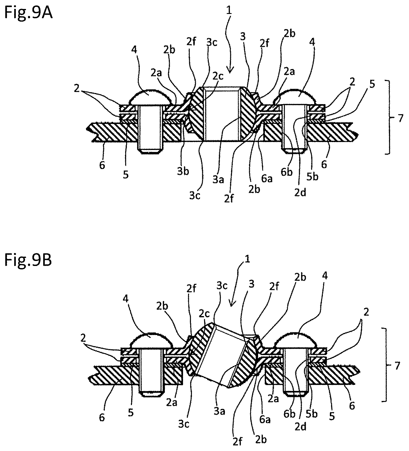
[0018] FIG. 9(a) is a cross-sectional view illustrating a nozzle device of a second embodiment of the present invention. FIG. 9(b) is a cross-sectional view illustrating a state in which the outflow direction is changed.
[0019] FIG. 10(a) is a cross-sectional view illustrating an application example of the nozzle device illustrated in FIG. 9. FIG. 10(b) is a cross-sectional view illustrating a state in which the outflow direction is changed.
[0020] FIG. 11(a) is a cross-sectional view illustrating a nozzle device of a third embodiment of the present invention. FIG. 11(b) is a cross-sectional view illustrating an outflow stop state of the nozzle device.
[0021] FIG. 12 is a schematic view illustrating a fluid outflow mechanism including the nozzle device of the present invention.
[0022] FIG. 13(a) is a perspective view illustrating a nozzle device of a fourth embodiment of the present invention. FIG. 13(b) is a rear view illustrating the flow path wall with the nozzle unit attached thereto of a fourth embodiment of the present invention.
[0023] FIG. 14 is a cross-sectional view illustrating a modification of the nozzle device of the fourth embodiment of the present invention.
DESCRIPTION OF EMBODIMENTS
[0024] Hereinafter, embodiments of the present invention will be described.
[0025] Nozzle device 7 of a first embodiment of the present invention illustrated in FIGS. 1 and 2 includes nozzle unit 1 and a flow path body having nozzle unit 1 attached thereto. Nozzle unit 1 includes pair of thin plate members 2, nozzle body 3, screw 4 that is an example of a securing member, and gasket 5. Each thin plate member 2 includes flat portion 2a, contact holding portion 2b that is formed by being bent from flat portion 2a, hollow portion 2c (see FIG. 2) of contact holding portion 2b that is tapered away from flat portion 2a, and at least two fixing holes 2d provided outside contact holding portion 2b. Pair of thin plate members 2 are disposed so as to substantially overlap with each other with or without a space therebetween. In this state, hollow portions 2c substantially overlap with each other to constitute a holding space. Contact holding portion 2b is bent from flat portion 2a of thin plate member 2 and extends substantially in a thickness direction of flat portion 2a toward an opposite side to a surface where flat portions 2a face each other. As illustrated in FIG. 2, contact holding portion 2b has a tapered shape where inner diameter d2 of hollow portion 2c of distal end portion 2f is smaller than inner diameter d1 of hollow portion 2c of root portion 2e (connection portion between contact holding portion 2b and flat portion 2a). Therefore, the portion of contact holding portion 2b which is bent from flat portion 2a of thin plate member 2 extends in the thickness direction of flat portion 2a and in a direction toward the center of hollow portion 2c.
[0026] Nozzle body 3 of the present embodiment is held in a holding space and includes fluid passage 3a that is a through hole. The holding space is formed by connecting hollow portions 2c of contact holding portions 2a of pair of thin plate members 2. As illustrated in the drawing, nozzle body 3 has the shape in which the outer peripheral portion forms a part of a spherical surface.
[0027] The shape of nozzle body 3 may be formed by cutting the upper and lower end portions of the spherical body and has a short size in an up-and-down direction, so that nozzle body 3 is flattened. The outer diameter decreases from maximum outer diameter portion 3b, which is located substantially at the center in a longitudinal direction of fluid passage 3a, toward both end portions 3c in the longitudinal direction of fluid passage 3a. Specifically, outer diameter D1 of maximum outer diameter portion 3b is larger than outer diameter D2 of both end portions 3c, smaller than inner diameter d1 of hollow portion 2c of root portion 2e of contact holding portion 2b, and larger than inner diameter d2 of hollow portion 2c of distal end portion 2f Therefore, in an assembled state (FIG. 1(a)), nozzle body 3 cannot be detached from hollow portion 2c of contact holding portion 2b. As a result, nozzle body 3 is inserted into a holding space formed by connecting hollow portions 2c, and nozzle body 3 is rotatably held in a state in which maximum outer diameter portion 3b is positioned inside the holding space. By rotating nozzle body 3 inside the holding space, it is possible to change the direction of fluid passage 3a and to change the outflow direction of the fluid from nozzle unit 1. Preferably, nozzle body 3 is not detachable from the holding space. As described above, pair of thin plate members 2 constitute a holding mechanism of nozzle body 3.
[0028] Gasket 5 is sandwiched between a pair of substantially overlapping thin plate members 2 and flow path wall 6 (virtually illustrated by a two-dot chain line in FIG. 1(a)) of the flow path body to which nozzle unit 1 is attached. Gasket 5 is made of an elastic material such as rubber.
[0029] Gasket 5 has substantially the same outer peripheral contour of planar shape as the outer peripheral contour of planar shape of flat portion 2a of thin plate member 2. Gasket 5 includes central hole 5a through which contact holding portion 2b can pass, and fixing holes 5b each facing fixing hole 2d. However, if high level of sealing performance is not required, gasket 5 may be omitted.
[0030] Screw 4, which is an example of the securing member, passes through mutually overlapping fixing holes 2d and 5b of pair of overlapping thin plate members 2 and gasket 5, and screw 4 is threaded into and fixed to flow path wall 6.
[0031] Specifically, pair of thin plate members 2 are disposed at positions that cover hole portion 6a in flow path wall 6 of the flow path body, and gasket 5 is located between the pair of thin plate members 2 and flow path wall 6. Screw 4 passing through substantially overlapping fixing holes 2d and 5b is threaded into and fixed to threaded hole 6b provided outside hole portion 6a of flow path wall 6. In this manner, by threading screw 4 into threaded hole 6b, pair of thin plate members 2 are fixed to flow path wall 6 with gasket 5 interposed therebetween. Then, nozzle body 3 is rotatably held in a holding space of thin plate members 2 due to the difference between outer diameter D1 of maximum outer diameter portion 3b, and inner diameters d1, d2 of root portion 2e and distal end portion 2f of hollow portion 2c of contact holding portion 2b of thin plate member 2. Therefore, the direction of fluid passage 3a, that is, the fluid outflow direction can be freely changed by rotating nozzle body 3 inside the holding space of thin plate members 2 which are fixed to flow path wall 6 of the flow path body.
[0032] FIG. 3(a) illustrates an example in which the fluid outflow direction is inclined to the left in the drawing. FIG. 3(b) illustrates an example in which the fluid outflow direction is inclined to the right in the drawing. In this manner, nozzle body 3 is rotatable inside the holding space while the spherical surface on an outer periphery of nozzle body 3 is sliding along an inner surface of contact holding portion 2b of thin plate member 2. Nozzle body 3 can be rotated 360 degrees in a plane parallel to flat portion 2a of thin plate member 2. In the thickness direction of flat portion 2a of thin plate member 2, as illustrated in FIGS. 3(a) and 3(b), nozzle body 3 can be inclined as long as nozzle body 3 is not detached from distal end portion 2f of hollow portion 2c of holding contact portion 2b of thin plate member 2. When the outer peripheral portion of nozzle body 3 and an inner peripheral portion of contact holding portion 2b of thin plate member 2 are formed with high accuracy, they are in close contact with each other to generate a frictional force. Due to the frictional force, nozzle body 3 which has been moved to a position can be continuously held at that position. In this case, nozzle body 3 can be rotated again to change again the outflow position and the outflow direction of the fluid by applying an external force, for example, by manually rotating nozzle body 3. Easily moving of nozzle body 3 in the holding space and the prevention of unintended positional shift of nozzle body 3 which has been moved to a position, are contradictory requirements. The balance between the requirements is appropriately set by appropriately adjusting the degree of tightening of screw 4 to adjust the distance between both thin plate members 2. At this time, nozzle body 3 may be sandwiched by contact holding portions 2b of pair of thin plate members 2 while being pressed with a predetermined pressure and may be rotatably held. Alternatively, nozzle body 3 may be sandwiched by contact holding portion 2b without being pressed and may be rotatably held.
[0033] Nozzle unit 1 of the present invention can be attached to flow path wall 6 of the flow path body such as a pipe simply by fixing pair of thin plate members 2 by screw 4. A large housing as in the inventions described in Patent Documents 1 and 2 is not required, and nozzle body 3 can be rotatably held only by contact holding portions 2b formed by bending a part of thin plate member 2. Thus, the overall size of nozzle unit 1, particularly the dimension in a direction vertical to flow path wall 6 (in a thickness direction of flat portion 2a of thin plate member 2) can be kept very small. Nozzle unit 1 having a small size is light, and thus flow path wall 6 does not require a large space and high strength. As a result, there is a very small restriction on the mounting position of nozzle unit 1, that is, the fluid outflow position. Therefore, it is possible to greatly improve freedom in arranging the mounting position (outflow position).
[0034] As illustrated in FIG. 1(b), flat portion 2a of thin plate member 2 of nozzle unit 1 and gasket 5 of the present embodiment have a substantially parallelogram planar shape that is long in one direction and short in a direction orthogonal thereto. FIGS. 4(a) and 4(b) illustrate nozzle device 7 having a structure in which nozzle unit 1 is attached to pipe 13A (flow path body) having a square cross section. Further, FIGS. 4(c) and 4(d) illustrate a state in which nozzle unit 1 of the present embodiment is attached to pipe 13B (flow path body) having the smaller square cross section. As described above, when the length of one side of a square cross section of pipe 13B is shorter than a long side of a planar shape of flat portion 2a of thin plate member 2 and gasket 5, nozzle unit 1 can be obliquely attached such that the long sides of flat portion 2a of thin plate member 2 and gasket 5 are inclined relative to a direction in which pipe 13B extends. In particular, when a plurality of nozzle units 1 are attached to one pipe 13B, the pitch of fluid passage 3a (outflow position) of nozzle unit 1 can be reduced. The reduction of the pitch can be achieved by arranging nozzle unit 1 such that the long sides of flat portion 2a of thin plate member 2 and gasket 5 are inclined relative to the direction in which pipe 13B extends. Furthermore, although not illustrated, when the pipe is smaller, nozzle unit 1 can be attached such that the direction in which the pipe extends is parallel to the long sides of flat portion 2a of thin plate member 2 and gasket 5.
[0035] Furthermore, as illustrated in FIGS. 4(e) and 4(f), when nozzle unit 1 of the present embodiment is attached to pipe 13C (fluid flow path) having a circular cross section, nozzle unit 1 can be easily attached by forming flat portion 2a of thin plate member 2 in a curved shape according to a curvature of an outer peripheral surface (flow path wall 6) of pipe 13C. Gasket 5 is made of an elastic material, and thus has flexibility. Therefore, gasket 5 can be curved according to the curvature of flow path wall 6 of pipe 13C. In particular, when nozzle unit 1 is disposed such that the direction in which pipe 13C extends is parallel to the long sides of flat portion 2a of thin plate member 2 and gasket 5, nozzle unit 1 can be attached by curving the short side of flat portion 2a of thin plate member 2. Therefore, it is possible to reduce the amount of curving, so that machining and mounting of nozzle unit 1 may become easy. As described above, nozzle unit 1 can be easily attached to various flow path walls 6 by partially curving thin plate member 2 according to the shape of flow path wall 6 to which nozzle unit 1 is attached.
[0036] Flow path body 6 having flow path wall 6 to which nozzle unit 1 of the present invention is attached is not limited to a pipe, and flow path body 6 may be various members such as the housing of a tank-like container. The mounting surface (flow path wall) is not limited to a flat surface, and nozzle unit 1 may be attached to a curved surface as illustrated in FIG. 4(f). The reason for this is that in the present invention, the member for holding nozzle body 3 does not have to be a large rigid housing including a three-dimensional mounting space as in Patent Documents 1 and 2, and it may be thin plate member 2 that can be easily curved. When fluid flows out of nozzle device 7, even in a tank-like container and the like, the fluid flows toward fluid passage 3a of nozzle unit 1 thereinside, and thus the tank-like container and the like are also regarded as a kind of the flow path body.
[0037] FIG. 5 illustrates a modification of nozzle device 7 of the present embodiment. In this modification, the outer peripheral portion of flat portion 2a of thin plate member 2 on a side close to flow path wall 6 (for example, a wall surface of the pipe) is bent in a direction toward flow path wall 6 (a direction on an opposite side to the surface on which flat portions 2a of thin plate members 2 face each other, that is, the same direction as the direction in which the contact holding portion 2b extends). This bent portion 2g is located so as to surround the outer peripheral portion of gasket 5 from outside. Therefore, when gasket 5 is pressed to flat portion 2a of pair of thin plate members 2 by threading screw 4 into threaded hole 6b of flow path wall 6, bent portion 2g can prevent compressed gasket 5 from spreading outward and protruding outside the outer peripheral portion of thin plate member 2. Gasket 5 functions to prevent the fluid from leaking from a gap between flat portion 2a of thin plate member 2 and wall surface 6 of the pipe. If this gasket 5 is compressed to be so thin as to extend outside of the outer peripheral portion of flat portion 2a of thin plate member 2, there is a decrease in the effectiveness of preventing the leakage of fluid. In contrast to this, in the present modification, bent portion 2g can prevent gasket 5 from extending outside and can maintain the effect of preventing leakage.
[0038] The securing member of nozzle unit 1 is not limited to screw 4 illustrated in FIGS. 1 and 2. For example, although not illustrated, a screw with a pointed tip (so-called tapping screw) can also be used as the securing member. In this case, a threaded hole need not be formed in advance in flow path wall 6 such as a wall surface of a pipe. This then reduces processes for machining on flow path wall 6 to which nozzle unit 1 is attached, thereby simplifying the work and expanding the selection range of the flow path body to which nozzle unit 1 is attached. Further, according to the modification illustrated in FIG. 6, rivet 9 can also be used as the securing member. In this case, instead of a threaded hole, a simple through-hole is formed in flow path wall 6. Rivet 9 penetrates through fixing holes 2d and 5b and the through-hole and is crimped, whereby pair of thin plate members 2 and gasket 5 can be undetachably fixed to flow path wall 6. To crimp rivet 9, a space is required for the operation of pressing a distal end portion of rivet 9 that has passed through the through hole. When screw 4 is used as the securing member as illustrated in FIGS. 1 to 5, the pressure, which is applied to nozzle body 3 by contact holding portions 2b to hold nozzle body 3, can be adjusted by the degree of tightening of screw 4. When rivet 9 is used as the securing member as illustrated in FIG. 6, the pressure can be adjusted by the degree of crimping of rivet 9. Contact holding portion 2b can be configured not to press nozzle body 3 to hold nozzle body 3.
[0039] FIG. 7 illustrates another modification of nozzle device 7 of the present embodiment. In this modification, the inner surface and the outer surface of contact holding portion 2b are not spherical surfaces, but inclined flat surfaces. In this case, a part of the spherical surface on the outer periphery of nozzle body 3 is not in contact with the inner peripheral surface of contact holding portion 2b, which facilitates rotation of nozzle body 3. However, the complicated process of forming the curved surface with high accuracy is not necessary. As a result, the work of forming contact holding portion 2b becomes much easier.
[0040] In another modification illustrated in FIG. 8, each fluid passage 3a has a continuously expanding shape from a central portion in the longitudinal direction toward both end portions. This structure is suitable for widely and radially ejecting the fluid from nozzle unit 1.
[0041] As described above, at a stage before nozzle unit 1 mainly comprising pair of thin plate members 2, nozzle body 3, securing members (screw 4, rivet 9, or the like), and gasket 5 is attached to flow path wall 6 of the flow path body (pipes 13A to 13C and the like), pair of thin plate members 2 and gasket 5 overlap with each other, securing members 4 and 9 penetrate through fixing holes 2d and 5a, and then the distal end portions of securing members 4 and 9 that penetrate through fixing holes 2d and 5a are preferably covered, for example, with a resin cap, although this is not illustrated. As a result, it is possible to prevent the person who is handling nozzle unit 1 from being injured by the distal end portions of securing members 4 and 9. Further, the cap acts as a retainer for securing members 4 and 9 and maintains the state in which nozzle unit 1 can be easily carried around without disassembling each member thereof
[0042] FIGS. 9(a) and 9(b) illustrate nozzle device 7 of a second embodiment of the present invention. One end portion (upper end portion in FIG. 9(a)) of nozzle body 3 of the present embodiment has an end surface in which a part of the spherical body is cut off, as in the first embodiment (FIGS. 1 to 8). At the other end portion (lower end portion in FIG. 9(a)) of nozzle body 3 of the present embodiment, spherical body is not cut off and the spherical shape which has almost no end surface is kept. Fluid passage 3a is formed from the one end portion to the other end portion of nozzle body 3. Further, a female thread portion is formed in an inner surface of fluid passage 3a. This nozzle body 3 is configured, as in the first embodiment, such that the outer diameter continuously decreases from maximum outer diameter portion 3b located substantially at the center in the longitudinal direction of fluid passage 3a toward both end portions 3c (the above-described one end portion and the other end portion) in the longitudinal direction of fluid passage 3a. Specifically, outer diameter D1 of maximum outer diameter portion 3b is larger than outer diameter D2 of both end portions 3c, smaller than inner diameter d1 of fluid passage 3a, and larger than inner diameter d2 of distal end portion 2f of hollow portion 2c of contact holding portion 2b (see FIG. 2). As a result, nozzle body 3, which is inserted into the holding space formed by connecting hollow portions 2c, is rotatably held between distal end portions of contact holding portions 2b of overlapping both thin plate members 2. This structure simplifies the machining process of forming nozzle body 3.
[0043] FIGS. 10(a) and 10(b) illustrate an application example of the present embodiment. As described above, a female thread portion is formed in fluid passage 3a of the present embodiment. Hollow pipe member 10 is attached to nozzle body 3, and at least a part of hollow pipe member 10 has a male thread portion to be threaded into the female thread portion. Nozzle unit 1 of the present invention has an advantage in which the dimension in a direction vertical to flow path wall 6 (in the thickness direction of flat portion 2a of thin plate member 2) is very small. However, a longer outflow path may be required in order to improve the fluid outflow performance (ejection performance). In this case, as illustrated in FIG. 9(a), pair of thin plate members 2 and gasket 5 are attached to flow path wall 6 of the flow path body (wall surface such as a pipe) by the securing member (screw 4 or the like), and then, as illustrated in FIG. 10(a), pipe member 10 is attached to nozzle body 3 by threading the male thread portion of pipe member 10 into the female thread portion of fluid passage 3a. Pipe member 10 becomes an extension portion of fluid passage 3a and configures a long outflow path. As a result, at a stage before attachment of nozzle unit 1 to flow path wall 6 by securing member 4, the dimensions in the thickness direction of pair of thin plate members 2, gasket 5 and nozzle body 3 are kept very small so that it is easy to handle and attach nozzle unit 1. After attachment of nozzle unit 1, the fluid outflow performance (ejection performance), for example, the accuracy of the outflow direction, can be improved by using pipe member 10. Thus, in the state in which pipe member 10 is attached and the outflow path becomes long, as illustrated in FIG. 10(b), the fluid outflow direction can be changed by integrally rotating nozzle body 3 and pipe member 10. In this structure, to stop the fluid outflow, instead of pipe member 10, a plug (not shown in the drawings) may be attached to nozzle body 3. At least a part of plug has a male thread portion to be threaded into a female thread portion.
[0044] FIGS. 11(a) and 11(b) illustrate nozzle device 7 of a third embodiment of the present invention. Nozzle body 3 of the present embodiment has a shape in which fluid passage 3a is formed in a spherical body, and the spherical body is not cut off in both end portions 3c in the longitudinal direction of fluid passage 3a, and nozzle body has almost no end surface in the longitudinal direction. This structure further simplifies the machining process of forming nozzle body 3. This nozzle body 3 is configured, as in the first and second embodiments, such that the outer diameter continuously decreases from maximum outer diameter portion 3b located substantially at the center in the longitudinal direction of fluid passage 3a toward both end portions 3c in the longitudinal direction of fluid passage 3a. Specifically, outer diameter D1 of maximum outer diameter portion 3b is larger than the outer diameter of both end portions 3c (substantially equal to the inner diameter of fluid passage 3a), smaller than inner diameter d1 of root portion 2e of hollow portion 2c, and larger than inner diameter d2 of distal end portion 2f (see FIG. 2). As a result, nozzle body 3 inserted into the holding space composed of pair of hollow portion 2c is rotatably held between distal end portions 2f of contact holding portions 2b of overlapping both thin plate members 2. Nozzle body 3 of the present embodiment is a substantially spherical body, and thus can rotate 360 degrees in a plane parallel to flat portion 2a of thin plate member 2 and can also rotate substantially 360 degrees in the thickness direction of flat portion 2a of thin plate member 2. Notch portion 3d (not limited to one portion) is provided on an outer periphery of nozzle body 3. Nozzle body 3 can be easily rotated by hooking a tool (not illustrated) or the like in this notch portion 3d. As described above, in the present embodiment, nozzle body 3 has a very high degree of freedom of rotation and can be almost freely rotated. In this structure, to stop the fluid outflow, as illustrated in FIG. 11(b), nozzle unit may be rotated such that fluid passage 3a may be parallel to a plate surface of flat portion 2a of thin plate member 2 and that both end portions of fluid passage 3a may be covered with contact holding portion 2a. This structure prevents nozzle body 3 from being detached from between the pair of contact holding portions 2a.
[0045] As illustrated in FIG. 12, nozzle unit 1 of each embodiment described above can be attached to flow path wall 6 of pipes (flow path body) constituting the piping, thereby configuring nozzle device 7. Pump 11 for generating a pressure to eject the fluid is connected to this flow path body. For example, in a machine tool, nozzle device 7 can easily supply a liquid coolant toward a tool for machining and a machined portion of a workpiece. One outflow portion may be configured by attaching one nozzle unit 1 to one pipe. However, as illustrated in FIG. 12, a plurality of nozzle units 1 may also be attached to one flow path wall 6 (pipe), thereby configuring a plurality of outflow portions and simultaneously supplying a fluid (for example, coolant) to a plurality of places. Further, although not illustrated, a plurality of nozzle units 1 may also be attached to a wall surface of flow path wall 6 (container) containing the liquid, thereby forming an outflow mechanism for ejecting the liquid directly from the container.
[0046] FIG. 13 illustrates nozzle device 7 of a fourth embodiment of the present invention. FIG. 13(a) is a perspective view of nozzle device 7 of the present embodiment. FIG. 13(b) is a rear view illustrating a surface, which faces inward of flow path body 8, of flow path wall 8a of flow path body 8 of nozzle device 7 of the present embodiment as viewed in the direction of arrow A. In flow path body 8 of the present embodiment, one flow path wall 8a is not integral with the other portion (main body portion 8b), but is formed as a separate member. A plurality of nozzle units 1 are attached to flow path wall 8a that is this separate member. At this time, nozzle unit 1 is attached to the inner surface of flow path wall 8a (surface facing inward of flow path body 8). Therefore, when this flow path body 8 is viewed from outside, except for fluid passages 3a exposed from the hole portions of flow path wall 8a and except for the distal end portions of screws 4 (securing members) exposed from the fixing holes, most portions of nozzle unit 1 are covered and hidden by flow path wall 8a. In other words, in a state of being hardly visible from outside except for fluid passage 3a and without impairing the appearance, nozzle unit 1 has the advantage of enabling the liquid to flow out and has the advantage of freely changing the outflow direction as in each of the above-described embodiments. FIG. 13 illustrates nozzle device 7 comprising three nozzle units 1, wherein each of three nozzle units 1 have different fluid outflow directions from each other, as indicated by the opening direction of fluid passage 3a. If rivet 9 similar to that illustrated in FIG. 6 is used as the securing member, rivet 9 can be lightly crimped to adjust the distance between thin plate member 2 and the flow path wall and to adjust the pressure applied to the nozzle body.
[0047] According to the present embodiment, nozzle unit 1 is attached to flow path wall 8a that is one plate member before being joined to main body portion 8b of flow path body 8. Then, flow path wall 8a having nozzle unit 1 attached thereto is joined to main body portion 8b to configure flow path body 8, which completes nozzle device 7. This method can easily attach nozzle unit 1 to the surface inside flow path wall 8a as illustrated in FIG. 13. Thus, according to this method, the operation (especially the mounting operation of nozzle unit 1) is much easier than the method of attaching nozzle unit 1 to the completed pipe-like or container-like flow path body.
[0048] In the present embodiment, when the fixing hole is formed not as a through-hole but as a bottomed hole which is opened only in an inner surface of the flow path wall, screw 4 can reach only a middle portion of flow path wall 8a in its plate thickness direction, as illustrated in FIG. 14. The distal end portion of screw 4 is invisible from outside, and nothing is visible except for fluid passage 3a that is a hole through which the fluid flows out. Therefore, the effects of the present invention can be obtained without impairing the appearance. Further, in the present embodiment, when the fluid should not flow out, plug 12 for closing fluid passage 3a can be attached as illustrated in FIG. 14. As in the structure illustrated in FIG. 9, when a female thread portion is preliminarily formed in the fluid passage, plug 12 having a male thread portion can be used to thread the male thread portion into the female thread portion, thereby fixing plug 12 to fluid passage 3a, in order to prevent the fluid from flowing out. Alternatively, when the fluid should not flow out, fluid passage 3a may also be blocked by contact holding portion 2b so as not to be exposed as in the state illustrated in FIG. 11(b).
[0049] Thin plate member 2, nozzle body 3 and securing member (screw 4, rivet 9, and the like) constituting nozzle unit 1 of the present invention may be made of metal or resin. Pipe member 10 illustrated in FIGS. 10(a) and 10(b) may also be made of metal or resin. However, these members may be made of a material other than metal and resin. Gasket 5 is preferably made of an elastic resin material. The unillustrated cap is also preferably made of resin. However, the gasket and the cap may be made of a material other than resin (for example, metal).
[0050] As described above, the present invention can provide nozzle unit 1 and nozzle device 7 that are very compact, especially very small in the thickness direction (direction vertical to flow path walls 6 and 8a), and can be reduced in weight. As a result, flow path walls 6 and 8a (nozzle attachment portions of the piping and the housing) of the flow path body do not require large space and high strength, and thus this extremely reduces restrictions on the attachment position. Further, this nozzle unit 1 can change the direction of fluid passage 3a in an easy and relatively free manner, and the outflow position and the outflow direction of the fluid can be set arbitrarily. Furthermore, the operation of accommodating nozzle body 3 between pair of thin plate members 2 is very easy, and thus the manufacturing process of nozzle device 7 is extremely simple as compared to the invention described in Patent Document 1 which requires the pressing of the spherical body into the housing. Nozzle unit 1 of the present invention can be very easily attached and detached. When screw 4 is used as the securing member, there is no need to use a spanner or the like, and nozzle unit 1 can be fixed by one screwdriver, thereby requiring a small work space for attachment. As in the inventions described in Patent Documents 1 and 2, when a part of the nozzle housing itself constitutes the male thread portion, the attached nozzle forms a protrusion greatly protruding outward from the wall surface (attachment portion) of an external member such as a pipe. However, nozzle unit 1 of the present invention has a very small amount of protrusion outward from flow path walls 6 and 8a, which is not so noticeable and is not impeditive.
Explanation of Reference Numerals
[0051] 1 nozzle [0052] 2 thin plate member [0053] 2a flat portion [0054] 2b contact holding portion [0055] 2c hollow portion [0056] 2d fixing hole [0057] 2e root portion [0058] 2f distal end portion [0059] 3 nozzle body [0060] 3a fluid passage [0061] 3b maximum outer diameter portion [0062] 3c end portion [0063] 4 screw (securing member) [0064] 5 gasket [0065] 5a central hole [0066] 5b fixing hole [0067] 6 flow path wall [0068] 6a hole portion [0069] 6b threaded hole [0070] 7 nozzle device [0071] 8 flow path body [0072] 8a flow path wall [0073] 8b main body portion [0074] 9 rivet (securing member) [0075] 10 pipe member [0076] 11 pump [0077] 12 plug [0078] 13A, 13B, 13D pipe (flow path body)
* * * * *
D00000
D00001
D00002
D00003
D00004
D00005
D00006
D00007
D00008
D00009
D00010
D00011
D00012

XML
uspto.report is an independent third-party trademark research tool that is not affiliated, endorsed, or sponsored by the United States Patent and Trademark Office (USPTO) or any other governmental organization. The information provided by uspto.report is based on publicly available data at the time of writing and is intended for informational purposes only.
While we strive to provide accurate and up-to-date information, we do not guarantee the accuracy, completeness, reliability, or suitability of the information displayed on this site. The use of this site is at your own risk. Any reliance you place on such information is therefore strictly at your own risk.
All official trademark data, including owner information, should be verified by visiting the official USPTO website at www.uspto.gov. This site is not intended to replace professional legal advice and should not be used as a substitute for consulting with a legal professional who is knowledgeable about trademark law.