Resistance-adjustable Stationary Bicycle
ZHOU; Yuzhi
U.S. patent application number 16/503102 was filed with the patent office on 2020-01-23 for resistance-adjustable stationary bicycle. The applicant listed for this patent is Xiamen Zhoulong Sporting Goods Co., Ltd.. Invention is credited to Yuzhi ZHOU.
| Application Number | 20200023222 16/503102 |
| Document ID | / |
| Family ID | 65334336 |
| Filed Date | 2020-01-23 |


| United States Patent Application | 20200023222 |
| Kind Code | A1 |
| ZHOU; Yuzhi | January 23, 2020 |
RESISTANCE-ADJUSTABLE STATIONARY BICYCLE
Abstract
Disclosed is a resistance-adjustable stationary bicycle. First, an adjustment motor is arranged and is connected to a magnetic damping washer though an adjustment steel rope, so that an electrical-control resistance adjustment system is established; and second, an adjustment knob is arranged, and the rotation angle and rotation direction of the adjustment knob can be read to adaptively drive the adjustment motor to wind or unwind the adjustment steel rope to adjust the distance between the magnetic damping washer and a flywheel, so as to realize resistance adjustment. The adjustment knob is easy and convenient to operate and high in adjustment precision, users can adjust the resistance in real time to a value meeting the current requirements when using the stationary bicycle, and the problem of inconvenient adjustment of the resistance of existing stationary bicycles is solved.
| Inventors: | ZHOU; Yuzhi; (XIAMEN CITY, CN) | ||||||||||
| Applicant: |
|
||||||||||
|---|---|---|---|---|---|---|---|---|---|---|---|
| Family ID: | 65334336 | ||||||||||
| Appl. No.: | 16/503102 | ||||||||||
| Filed: | July 3, 2019 |
| Current U.S. Class: | 1/1 |
| Current CPC Class: | A63B 21/225 20130101; A63B 21/00069 20130101; A63B 21/00192 20130101; A63B 22/0605 20130101; A63B 21/4035 20151001; A63B 21/0051 20130101; A63B 2071/0081 20130101; A63B 2225/50 20130101; A63B 2071/0675 20130101; A63B 21/015 20130101; A63B 2209/08 20130101; A63B 2225/09 20130101 |
| International Class: | A63B 21/00 20060101 A63B021/00; A63B 21/22 20060101 A63B021/22; A63B 22/06 20060101 A63B022/06 |
Foreign Application Data
| Date | Code | Application Number |
|---|---|---|
| Jul 19, 2018 | CN | 201821149450.7 |
Claims
1. A resistance-adjustable stationary bicycle, comprising a frame, wherein a magnetic damping washer and a flywheel are arranged on the frame, a permanent magnet layer is arranged on a peripheral wall of the flywheel, and the magnetic damping washer is movably arranged close to a periphery of the flywheel; a controller, an adjustment motor, and an adjustment knob are further arranged on the frame, the controller is electrically connected with the adjustment motor and the adjustment knob, and the adjustment motor is connected to the magnetic damping washer through an adjustment steel rope; the controller reads the amount of rotation of the adjustment knob to control the adjustment motor to wind or unwind the adjustment steel rope to control a distance between the magnetic damping washer and the flywheel, so as to realize resistance adjustment.
2. The resistance-adjustable stationary bicycle according to claim 1, wherein the magnetic damping washer has an end hinged to the frame and an end elastically connected to the frame through an elastic piece, and the elastic piece is able to apply a force to make the magnetic damping washer swing towards the flywheel; and the adjustment steel rope is connected to a free end of the magnetic damping washer through the frame.
3. The resistance-adjustable stationary bicycle according to claim 2, wherein the resistance-adjustable stationary bicycle further comprises a mounting plate fixed to the frame, and the free end of the magnetic damping washer is arranged between the mounting plate and the flywheel; the elastic piece is a compression spring having two ends respectively abutting against the mounting plate and the magnetic damping washer; and a limiting rod is arranged on the mounting plate and penetrates through the magnetic damping washer to be connected with a limiting block.
4. The resistance-adjustable stationary bicycle according to claim 1, wherein the controller is further connected with a communication module to be connected to a handheld electronic terminal device, so that the controller can control the adjustment motor through the external handheld electronic terminal device.
5. The resistance-adjustable stationary bicycle according to claim 1, wherein the resistance-adjustable stationary bicycle further comprises a handle part, and the adjustment knob is arranged on the handle part; the frame comprises a bottom frame, a seat support and a handlebar support, and the seat support and the handlebar support are fixed to the bottom frame in a V shape; and the handle part is arranged in a middle of the handlebar support in a vertical direction.
6. The resistance-adjustable stationary bicycle according to claim 5, wherein the resistance-adjustable stationary bicycle further comprises a brake pad and a steel brake cable; the handle part is pivoted to the handlebar support through a rotary shaft, and the brake pad is pivoted to a position, close to the flywheel, of the frame; and two ends of the steel brake cable are eccentrically connected to the handle part and the brake pad respectively, so that the handle part and the brake pad are linked together.
7. The resistance-adjustable stationary bicycle according to claim 6, wherein a crank is arranged at a lower end of the handle part, and one end of the steel brake cable is hooked on the crank.
8. The resistance-adjustable stationary bicycle according to claim 6, wherein the brake pad has an end pivoted to the frame and an end provided with a tension spring so as to be elastically connected to the frame through the tension spring; and the steel brake cable is connected to the brake pad to apply a force to the brake pad which in turn overcomes a resistance from the tension spring to rotate.
9. The resistance-adjustable stationary bicycle according to claim 2, wherein the resistance-adjustable stationary bicycle further comprises a handle part, and the adjustment knob is arranged on the handle part; the frame comprises a bottom frame, a seat support, and a handlebar support, and the seat support and the handlebar support are fixed to the bottom frame in a V shape; and the handle part is arranged in a middle of the handlebar support in a vertical direction.
10. The resistance-adjustable stationary bicycle according to claim 9, wherein the resistance-adjustable stationary bicycle further comprises a brake pad and a steel brake cable; the handle part is pivoted to the handlebar support through a rotary shaft, and the brake pad is pivoted to a position, close to the flywheel, of the frame; and two ends of the steel brake cable are eccentrically connected to the handle part and the brake pad respectively, so that the handle part and the brake pad are linked together.
11. The resistance-adjustable stationary bicycle according to claim 10, wherein a crank is arranged at a lower end of the handle part, and one end of the steel brake cable is hooked on the crank.
12. The resistance-adjustable stationary bicycle according to claim 10, wherein the brake pad has an end pivoted to the frame and an end provided with a tension spring so as to be elastically connected to the frame through the tension spring; and the steel brake cable is connected to the brake pad to apply a force to the brake pad which in turn overcomes a resistance from the tension spring to rotate.
13. The resistance-adjustable stationary bicycle according to claim 3, wherein the resistance-adjustable stationary bicycle further comprises a handle part, and the adjustment knob is arranged on the handle part; the frame comprises a bottom frame, a seat support, and a handlebar support, and the seat support and the handlebar support are fixed to the bottom frame in a V shape; and the handle part is arranged in a middle of the handlebar support in a vertical direction.
14. The resistance-adjustable stationary bicycle according to claim 13, wherein the resistance-adjustable stationary bicycle further comprises a brake pad and a steel brake cable; the handle part is pivoted to the handlebar support through a rotary shaft, and the brake pad is pivoted to a position, close to the flywheel, of the frame; and two ends of the steel brake cable are eccentrically connected to the handle part and the brake pad respectively, so that the handle part and the brake pad are linked together.
15. The resistance-adjustable stationary bicycle according to claim 14, wherein a crank is arranged at a lower end of the handle part, and one end of the steel brake cable is hooked on the crank.
16. The resistance-adjustable stationary bicycle according to claim 14, wherein the brake pad has an end pivoted to the frame and an end provided with a tension spring so as to be elastically connected to the frame through the tension spring; and the steel brake cable is connected to the brake pad to apply a force to the brake pad which in turn overcomes a resistance from the tension spring to rotate.
17. The resistance-adjustable stationary bicycle according to claim 4, wherein the resistance-adjustable stationary bicycle further comprises a handle part, and the adjustment knob is arranged on the handle part; the frame comprises a bottom frame, a seat support and a handlebar support, and the seat support and the handlebar support are fixed to the bottom frame in a V shape; and the handle part is arranged in a middle of the handlebar support in a vertical direction.
18. The resistance-adjustable stationary bicycle according to claim 17, wherein the resistance-adjustable stationary bicycle further comprises a brake pad and a steel brake cable; and the handle part is pivoted to the handlebar support through a rotary shaft, and the brake pad is pivoted to a position, close to the flywheel, of the frame; and two ends of the steel brake cable are eccentrically connected to the handle part and the brake pad respectively, so that the handle part and the brake pad are linked together.
19. The resistance-adjustable stationary bicycle according to claim 18, wherein a crank is arranged at a lower end of the handle part, and one end of the steel brake cable is hooked on the crank.
20. The resistance-adjustable stationary bicycle according to claim 18, wherein the brake pad has an end pivoted to the frame and an end provided with a tension spring so as to be elastically connected to the frame through the tension spring; and the steel brake cable is connected to the brake pad to apply a force to the brake pad which in turn overcomes a resistance from the tension spring to rotate.
Description
BACKGROUND OF THE INVENTION
1. Technical Field
[0001] The invention belongs to the technical field of fitness equipment, in particular to a resistance-adjustable stationary bicycle capable of realizing electrical adjustment of the resistance.
2. Description of Related Art
[0002] Magnetic damping washers are usually adopted by stationary bicycles to control the rotational resistance of the flywheel, that is to say, the frictional resistance between the magnetic damping washers and the flywheel can be adjusted to adjust the treading resistance of the pedals of the stationary bicycles.
[0003] In the prior art, the relative positions of the magnetic damping washer and the flywheel are generally manually adjusted to adjust the resistance of the stationary bicycles. However, the existing stationary bicycles have the following defects: (1) in order to meet the requirements for different resistances of operators in different performance statuses, the resistance should be rapidly and easily adjusted in the fitness process; and (2) under the condition of constant-resistance fitness, the resistance between the magnetic damping washer and the flywheel will be decreased when the magnetic damping washer is worn, which in turn leads to a non-uniform resistance, and in this case, the resistance should also be adjusted in time.
[0004] In view of these defects, Chinese Utility Model Patent Publication No. CN204017268U discloses a foldable stationary bicycle which is based on electromagnetic resistance control and comprises a front support, a rear support, a cushion, a handlebar tube, a pedal wheel mechanism, and an inertia wheel mechanism, wherein the middle of the front support is pivoted to the middle of the rear support; the inertial wheel mechanism comprises an inertia wheel and an electromagnet component, the inertia wheel is mounted at the bottom of the front support, and the electromagnet component is also mounted at the bottom of the front support and is matched with the inertia wheel so as to form a resistance against the inertia wheel; and the pedal wheel mechanism is mounted on the lower portion of the front support, is located above the inertia wheel mechanism, and is linked with the inertia wheel mechanism.
[0005] According to this technical solution, the resistance of the inertia wheel is accurately controlled through the electromagnet component; however, the electromagnet component is high in energy consumption and has a structural stability poorer than that of the magnetic damping washer. Thus, there is an urgent need for a magnetic damping washer-based stationary bicycle with the resistance capable of being conveniently and rapidly adjusted.
BRIEF SUMMARY OF THE INVENTION
[0006] The objective of the invention is to provide a resistance-adjustable stationary bicycle to solve the problem of inconvenient adjustment of the resistance of existing stationary bicycles.
[0007] The specific solution is as follows: a resistance-adjustable stationary bicycle comprises a frame, wherein a magnetic damping washer and a flywheel are arranged on the frame, a permanent magnet layer is arranged on a peripheral wall of the flywheel, and the magnetic damping washer is movably arranged close to the periphery of the flywheel; a controller, an adjustment motor and an adjustment knob are further arranged on the frame, the controller is electrically connected with the adjustment motor and the adjustment knob, and the adjustment motor is connected to the magnetic damping washer through an adjustment steel rope; and the controller reads the amount of rotation of the adjustment knob to control the adjustment motor to wind or unwind the adjustment steel rope to control the distance between the magnetic damping washer and the flywheel, so as to realize resistance adjustment.
[0008] Furthermore, the magnetic damping washer has an end hinged to the frame and an end connected to the frame through an elastic piece, and the elastic piece is able to apply a force to make the magnetic damping washer swing towards the flywheel; and the adjustment steel rope is connected to a free end of the magnetic damping washer through the frame.
[0009] Furthermore, the resistance-adjustable stationary bicycle further comprises a mounting plate fixed to the frame; the free end of the magnetic damping washer is arranged between the mounting plate and the flywheel; the elastic piece is a compression spring and has two ends respectively abutting against the mounting plate and the magnetic damping washer; and a limiting rod is arranged on the mounting plate and penetrates through the magnetic damping washer to be connected with a limiting block.
[0010] Furthermore, the resistance-adjustable stationary bicycle further comprises a handle part, and the adjustment knob is arranged on the handle part; the frame comprises a bottom frame, a seat support, and a handlebar support, and the seat support and the handlebar support are fixed to the bottom frame in a V shape; and the handle part is arranged in the middle of the handlebar support in the vertical direction.
[0011] Furthermore, the resistance-adjustable stationary bicycle further comprises a brake pad and a steel brake cable; the handle part is pivoted to the handlebar support through a rotary shaft, the brake pad is pivoted to a position, close to the flywheel, of the frame, and two ends of the steel brake cable are eccentrically connected to the handle part and the brake pad respectively, so that the handle part and the brake pad are linked together.
[0012] Furthermore, a crank is arranged at the lower end of the handle part, and one end of the steel brake cable is hooked on the crank. Furthermore, the brake pad has an end pivoted to the frame and an end provided with a tension spring so as to be elastically connected to the frame through the tension spring; and the steel brake cable is connected to the brake pad to apply a force to the brake pad which in turn overcomes the resistance from the tension spring to rotate.
[0013] The resistance-adjustable stationary bicycle of the invention has the following beneficial effects: first, the adjustment motor is arranged and is connected to the magnetic damping washer though the adjustment steel rope, so that an electrical-control resistance adjustment system is established; and second, the adjustment knob is arranged, and the rotation angle and rotation direction of the adjustment knob can be read to adaptively drive the adjustment motor to wind or unwind the adjustment steel rope to adjust the distance between the magnetic damping washer and the flywheel, so as to realize resistance adjustment. The adjustment knob is easy and convenient to operate and high in adjustment precision, users can adjust the resistance in real time to a value meeting the current requirements when treading on the stationary bicycle, and the problem of inconvenient adjustment of the resistance of existing stationary bicycles is solved.
BRIEF DESCRIPTION OF THE SEVERAL VIEWS OF THE DRAWINGS
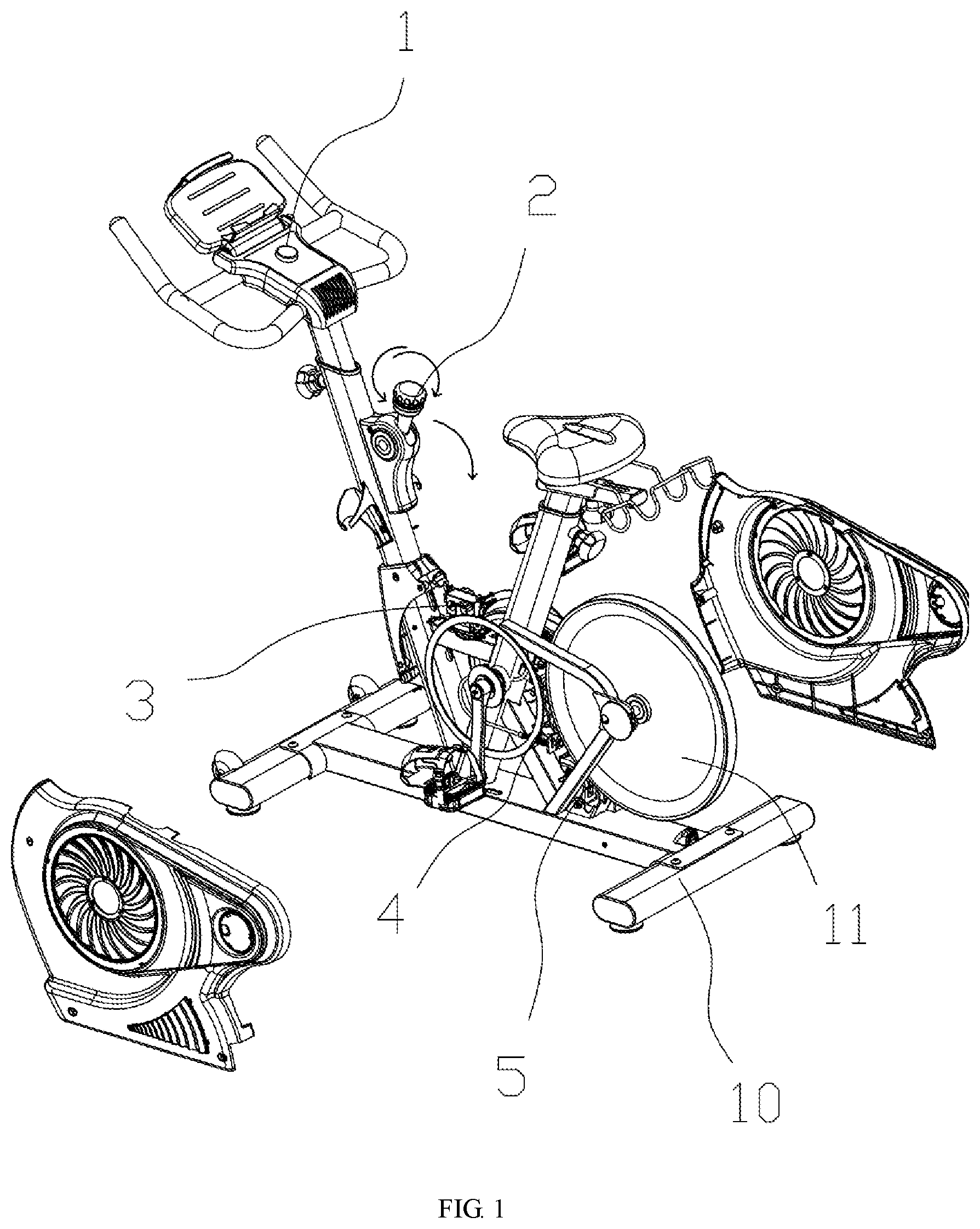
[0014] FIG. 1 is an exploded view of two side covers in one embodiment of the invention;
[0015] FIG. 2 is a further exploded view of FIG. 1;
[0016] FIG. 3 is a structural view of FIG. 2 with part of the components removed;
[0017] FIG. 4 is an enlarged view of part A in FIG. 3;
[0018] FIG. 5 is an enlarged view of part B in FIG. 3.
DETAILED DESCRIPTION OF THE INVENTION
[0019] The accompanying drawings are provided for a further description of the embodiments of the invention. These drawings belong to part of the contents disclosed by the invention and are mainly used for illustrating the embodiments and for explaining the operating principle of the embodiments in cooperation with the relevant description in the specification. By referring to these contents, those ordinarily skilled in the field can appreciate other possible embodiments and advantages of the invention. The components in the figures are not drawn to scale, and similar reference signs generally represent similar components.
[0020] The invention is further expounded below with reference to the accompanying drawings and embodiments.
[0021] As shown in FIG. 1 and FIG. 2, this embodiment provides a resistance-adjustable stationary bicycle which comprises a frame 10, wherein a magnetic damping washer 4 and a flywheel 11 are arranged on the frame 10, a permanent magnet layer is arranged on a peripheral wall of the flywheel 11, one side of the magnetic damping washer 4 is provided with a permanent magnet block to serve as a brake side, and the magnetic damping washer 4 is movably arranged close to the periphery of the flywheel 11.
[0022] Particularly, one end of the magnetic damping washer 4 is hinged to the frame 10 through a rotary shaft, the other end of the magnetic damping washer 4 is elastically connected to the frame 10 through an elastic piece, and the elastic piece is able to apply a force to make the magnetic damping washer 4 swing towards the flywheel 11. Preferably, a mounting plate is further arranged on the frame 10 and is fixed to a side, away from the flywheel 11, of the magnetic damping washer 4 on the frame 10, that is to say, the free end of the magnetic damping washer 4 is arranged between the mounting plate and the flywheel 11. Moreover, the elastic piece is preferably a compression spring having two ends respectively abutting against the mounting plate and the free end of the magnetic damping washer 4 so as to apply a force towards the flywheel 11 to the free end of the magnetic damping washer 4. Meanwhile, in order to prevent excessive swing of the magnetic damping washer 4, a limiting rod is arranged on the mounting plate, and the top of the limiting rod penetrates through the magnetic damping washer 4 to be connected with a limiting block, so that the magnetic damping washer 4 is limited.
[0023] To fulfill easy adjustment and control of damping, a controller 1, an adjustment motor 3, and an adjustment knob are further arranged on the frame 10. In this embodiment, the adjustment knob is arranged on a handle part 2; the controller 1 is electrically connected with the adjustment motor 3 and the adjustment knob, and then the adjustment motor 3 is connected to the free end of the magnetic damping washer 4 through an adjustment steel rope 34 particularly in such a manner: the adjustment steel rope 34 penetrates through the mounting base and is then hooked on the free end of the magnetic damping washer 4.
[0024] In this embodiment, damping adjustment is realized in the following way: the controller 1 reads the rotation variables of the adjustment knob on the handle part 2, namely the rotation direction and the rotation angle, to control the adjustment motor 3 to wind or unwind the adjustment steel rope 34, so as to control the swing angle of the magnetic damping washer 4 (to adjust the distance between the magnetic damping washer 4 and the flywheel 11), so that resistance adjustment is realized.
[0025] In this embodiment, the frame 10 comprises a bottom frame horizontally placed on the ground, a seat support provided with a seat, and a handlebar support provided with a handlebar part, wherein the seat support and the handlebar support are fixed to the bottom frame in a V shape, and the handle part 2 is arranged in the middle of the handlebar support in a vertical direction and exactly faces a position vertically below the arms to fulfill the optimum ergonomic effect, so that the adjustment knob of the handle part 2 can be adjusted most conveniently.
[0026] Furthermore, the controller 1 is connected with a communication module. Preferably, the communication module is a Bluetooth communication module through which the controller 1 is connected to a handheld electronic terminal device such as a mobile phone or a tablet computer, so that an operator can input parameter values to the controller via an APP on the external handheld electronic terminal device to control the adjustment motor 3 to work and thus realize resistance adjustment.
[0027] Referring to FIGS. 3-5, the resistance-adjustable stationary bicycle in this embodiment further comprises an emergency braking system. The emergency braking system comprises a brake pad 5 and a steel brake cable 6. The handle part 2 is pivoted to the handlebar support through a rotary shaft, the brake pad 5 is pivoted to a position, close to the flywheel 11, of the frame 10, and two ends of the steel brake cable 6 are eccentrically connected to the handle part 2 and the brake pad 5 respectively, so that the handle part 2 and the brake pad 5 are linked together.
[0028] Particularly, a crank is arranged at the lower end of the handle part 2, and one end of the steel brake cable 6 is hooked on the crank; the other end of the brake pad 5 is pivoted to the frame 10 and is provided with a tension spring 51 so as to be elastically connected to the frame 10 through the tension spring 51 or to move away from the flywheel 11 under the elastic effect; the steel brake cable 6 is connected to the brake pad 5; and when the handle part 2 is swung around the axis from top to bottom, the steel brake cable 6 is tensioned to apply a force to the brake pad 5 which in turn overcomes the resistance from the tension spring 51 to rotate to abut against the periphery of the flywheel 11, so that emergency braking is realized.
[0029] Although the invention is specifically illustrated and introduced in combination with preferred embodiments, those skilled in the art would appreciate that variations of the invention can be made in forms and in details without deviating from the spirit and scope defined by the claims, and all these variations should also fall within the protection scope of the invention.
* * * * *
D00000
D00001
D00002
D00003
D00004
D00005
XML
uspto.report is an independent third-party trademark research tool that is not affiliated, endorsed, or sponsored by the United States Patent and Trademark Office (USPTO) or any other governmental organization. The information provided by uspto.report is based on publicly available data at the time of writing and is intended for informational purposes only.
While we strive to provide accurate and up-to-date information, we do not guarantee the accuracy, completeness, reliability, or suitability of the information displayed on this site. The use of this site is at your own risk. Any reliance you place on such information is therefore strictly at your own risk.
All official trademark data, including owner information, should be verified by visiting the official USPTO website at www.uspto.gov. This site is not intended to replace professional legal advice and should not be used as a substitute for consulting with a legal professional who is knowledgeable about trademark law.