Novel Electrically Evoked Response (eer) Stimulator/amplifier Combination
Doran; Bruce
U.S. patent application number 16/515980 was filed with the patent office on 2020-01-23 for novel electrically evoked response (eer) stimulator/amplifier combination. The applicant listed for this patent is Diagnosys LLC. Invention is credited to Bruce Doran.
| Application Number | 20200023185 16/515980 |
| Document ID | / |
| Family ID | 69162301 |
| Filed Date | 2020-01-23 |


| United States Patent Application | 20200023185 |
| Kind Code | A1 |
| Doran; Bruce | January 23, 2020 |
NOVEL ELECTRICALLY EVOKED RESPONSE (EER) STIMULATOR/AMPLIFIER COMBINATION
Abstract
Apparatus for ophthalmic electrophysiological testing, the apparatus comprising: an EER stimulator for providing an electrical stimulus to an eye so as to evoke an electrophysiological response, wherein the EER stimulator comprises a power source; an amplifier for receiving the electrophysiological response and measuring that response, wherein the amplifier is integrated with the EER stimulator; and at least one switch disposed between the power source and the amplifier for isolating the power source from the amplifier when the electrical stimulus is delivered to the eye.
| Inventors: | Doran; Bruce; (Westford, MA) | ||||||||||
| Applicant: |
|
||||||||||
|---|---|---|---|---|---|---|---|---|---|---|---|
| Family ID: | 69162301 | ||||||||||
| Appl. No.: | 16/515980 | ||||||||||
| Filed: | July 18, 2019 |
Related U.S. Patent Documents
| Application Number | Filing Date | Patent Number | ||
|---|---|---|---|---|
| 62700055 | Jul 18, 2018 | |||
| Current U.S. Class: | 1/1 |
| Current CPC Class: | A61B 5/4005 20130101; A61B 5/04842 20130101; A61B 5/04001 20130101; A61B 5/04004 20130101; A61B 5/0478 20130101; A61B 5/0496 20130101; A61N 1/08 20130101; A61N 1/36046 20130101; A61N 1/0404 20130101 |
| International Class: | A61N 1/36 20060101 A61N001/36; A61B 5/04 20060101 A61B005/04; A61B 5/0496 20060101 A61B005/0496 |
Claims
1. Apparatus for ophthalmic electrophysiological testing, the apparatus comprising: an EER stimulator for providing an electrical stimulus to an eye so as to evoke an electrophysiological response, wherein the EER stimulator comprises a power source; an amplifier for receiving and measuring the electrophysiological response, wherein the amplifier is integrated with the EER stimulator; and at least one switch disposed between the power source and the amplifier for isolating the power source from the amplifier when the electrical stimulus is delivered to the eye.
2. Apparatus according to claim 1 wherein a first electrode is connected to the EER stimulator for delivering an electrical stimulus to the eye and for receiving an electrophysiological response from the eye.
3. Apparatus according to claim 2 wherein the first electrode comprises a corneal electrode.
4. Apparatus according to claim 1 wherein at least one second electrode is connected to the amplifier for receiving an electrophysiological response from the visual cortex.
5. Apparatus according to claim 4 wherein the at least one second electrode is a scalp electrode.
6. Apparatus according to claim 4 wherein the at least one second electrode comprises three scalp electrodes.
7. Apparatus according to claim 1 wherein the at least one switch is a fast-acting computer-controlled switch.
8. Apparatus according to claim 7 wherein the at least one switch comprises two switches.
9. Apparatus according to claim 7 wherein the at least one switch comprises (i) a switch disposed between the power source and the first electrode, and (ii) a switch disposed between the first electrode and the amplifier.
10. Apparatus according to claim 1 wherein the EER stimulator comprises a watchdog circuit for monitoring the electrical stimulus provided to an eye.
11. Apparatus according to claim 1 wherein the electrical stimulus is symmetrical about a baseline voltage.
12. Apparatus according to claim 1 wherein the amplifier is a highly linear 5-channel-32-bit medical amplifier.
13. A method for ophthalmic electrophysiological testing, the method comprising: providing apparatus comprising: an EER stimulator for providing an electrical stimulus to an eye so as to evoke an electrophysiological response, wherein the EER stimulator comprises a power source; an amplifier for receiving and measuring the electrophysiological response, wherein the amplifier is integrated with the EER stimulator; and at least one switch disposed between the power source and the amplifier for isolating the power source from the amplifier when the electrical stimulus is delivered to the eye; electrically isolating the power source from the amplifier; delivering an electrical stimulus to the eye using a first electrode connected to the EER stimulator; electrically isolating the power source from the first electrode and electrically connecting the first electrode to the amplifier; and capturing an electrophysiological response via the first electrode and using the amplifier to measure the electrophysiological response.
14. A method according to claim 13 wherein the first electrode comprises a corneal electrode.
15. A method according to claim 13 further comprising: capturing an electrophysiological response via at least one second electrode connected to the amplifier.
16. A method according to claim 15 wherein the at least one second electrode captures an electrophysiological response from the visual cortex.
17. A method according to claim 16 wherein the at least one second electrode is a scalp electrode.
18. A method according to claim 16 wherein the at least one second electrode comprises three scalp electrodes.
19. A method according to claim 13 wherein the at least one switch is a fast-acting computer-controlled switch.
20. A method according to claim 19 wherein the at least one switch comprises two switches.
21. A method according to claim 20 wherein the at least one switch comprises (i) a switch disposed between the power source and the first electrode, and (ii) a switch disposed between the first electrode and the amplifier.
21. A method according to claim 13 wherein the EER stimulator comprises a watchdog circuit for monitoring the electrical stimulus provided to an eye.
22. A method according to claim 13 wherein the electrical stimulus is symmetrical about a baseline voltage.
23. A method according to claim 13 wherein the amplifier is a highly linear 5-channel-32-bit medical amplifier.
Description
REFERENCE TO PENDING PRIOR PATENT APPLICATION
[0001] This patent application claims benefit of pending prior U.S. Provisional Patent Application Ser. No. 62/700,055, filed Jul. 18, 2018 by Diagnosys LLC and Bruce Doran for NOVEL EER STIMULATOR (Attorney's Docket No. DIAGNOSYS-8 PROV), which patent application is hereby incorporated herein by reference.
BACKGROUND OF THE INVENTION
[0002] Ophthalmic electrophysiology relates to electrophysiological measures of visual function. Ophthalmic electrophysiology is the only objective measure of visual function--all other ophthalmic diagnostics are either subjective or a measure of structure and not function.
[0003] One type of ophthalmic electrophysiology is electroretinography (ERG). ERG measures the electrical responses of various cell types in the retina, including the photoreceptors, inner retinal cells, and the ganglion cells. With ERG, flashes of light or moving patterns of light are used to stimulate the eye, and the resulting electrical response of the retina is detected from electrodes applied to the cornea.
[0004] Another type of ophthalmic electrophysiology is visual evoked potential (VEP). With VEP, light is used to stimulate the eye, and the resulting electrical response of the visual cortex is detected using electrodes applied to the scalp above the visual cortex.
[0005] Still another type of ophthalmic electrophysiology is electrically evoked response (EER). With EER, the eye is stimulated electrically instead of optically, by introducing a small shaped pulse of current to the cornea. The resulting response is measured from the visual cortex via skin electrodes placed on the scalp.
[0006] EER is useful in determining the integrity of the visual system in circumstances where light cannot be used as a stimulus. It is most commonly used to assess salvageability in trauma cases, when the eye is filled with blood.
[0007] EER is also used to assess the integrity of remaining visual system function in no-light-perception patients who lack intact photoreceptors. Patients who lack photoreceptors may be candidates for developing therapies that can regenerate them. Unless post-retinal visual pathways remain intact, however, regeneration of the photoreceptors will not restore vision. Candidates for such therapies therefore need to be screened to exclude patients who will not benefit from treatment.
[0008] EER stimulation is not new to the field of ophthalmic electrophysiology, and electrical stimulators exist that can elicit the desired physiological response. Unfortunately, these electrical stimulators are stand-alone pieces of equipment which are separate from the amplifiers and data acquisition systems used to measure the electrical response from the patient. Consequently, existing electrical stimulators are hard to set up, difficult to standardize, and potentially hazardous to the patient.
SUMMARY OF THE INVENTION
[0009] The present invention provides a novel EER stimulator which avoids these shortcomings by being incorporated into a highly sensitive, highly linear 5-channel-32-bit medical amplifier. The novel EER stimulator/amplifier combination uses only standard amplifier connections to the patient to both deliver the electrical stimulus to the patient and to measure the response from the patient, enhancing ease-of-use, improving accuracy, and avoiding any possible harm to the patient that might result from the use of two unintegrated systems (i.e., stimulator and amplifier) with separate ground and control connections.
[0010] In addition to recording EER, the novel EER stimulator/amplifier combination is also capable of measuring an ERG response to an EER stimulus so as to assess retinal function. This capability is unique to the novel EER stimulator/amplifier combination of the present invention. More particularly, the EER system delivers the EER stimulus to the eye via a corneal electrode. In conventional systems, a second corneal electrode is required to measure the ERG response. Even if such an electrode were employed, however, the EER stimulus would be clipped by the input protection diodes of the amplifier reading the ERG response. These input protection diodes limit any voltage applied to their inputs to a value less than that required for effective EER stimulation. Consequently, the ERG response to a full EER stimulus cannot be measured using conventional equipment.
[0011] With the novel EER stimulator/amplifier combination of the present invention, the EER stimulator is isolated from the amplifier during EER stimulation by a fast-acting computer-controlled switch that can restore the amplifier connection as soon as the EER stimulus is complete. As a result, the full EER stimulus can be delivered to the cornea without amplifier clipping and, significantly, the same corneal electrode which is used to deliver the EER stimulation can also be used to detect the ERG response from the cornea. This arrangement also eliminates the need for a second corneal electrode in the same eye. In this way, the novel EER stimulator/amplifier combination of the present invention can measure both the retinal and the cortical response to an EER stimulus (i.e., the ERG and EER responses to an EER stimulus). This is not possible with conventional EER and ERG systems.
[0012] The integration of the EER stimulator with the data acquisition amplifier enhances both the safety and the accuracy of the EER stimulus. For example, it is possible to control the EER stimulus so that the current produced by the EER stimulator is completely symmetrical about the resting baseline patient voltage. This is important because otherwise the EER stimulator would impose, with each pulse, a DC potential across the patient which could ultimately result in plating electrode material into the eye. In order to ensure proper pulse symmetry, the current source should be monitored as it is applied to the patient. This is not possible unless the amplifier and the EER stimulator are closely integrated.
[0013] Another safety feature of this integration is that it permits the stimulus current to be measured both before and during its application to the patient. The hardware integrity can be checked prior to every pulse, and then confirmed during delivery. Measurement of the current pulse during stimulation confirms not only that the correct current is being delivered, but also verifies the integrity of the connections between device and patient, resulting in 100% verification that the correct stimulus has been applied.
[0014] Although the EER stimulus currents are applied only briefly to the patient, they exceed (by a large factor) the steady state leakage current allowed to be applied to a patient under ordinary conditions. For this reason it is important not only to control precisely the duration and amplitude of the applied currents, but also to ensure that the currents can neither be accidentally applied nor unintentionally be allowed to remain on. The integration of stimulator and amplifier facilitates this by making it practical to turn the power to the stimulator system completely off when it is not being used, and to limit the ground return current to a steady-state safe value (less than 10 .mu.A) at all times except during the stimulus pulse.
[0015] In one preferred form of the present invention, there is provided apparatus for ophthalmic electrophysiological testing, the apparatus comprising:
[0016] an EER stimulator for providing an electrical stimulus to an eye so as to evoke an electrophysiological response, wherein the EER stimulator comprises a power source;
[0017] an amplifier for receiving and measuring the electrophysiological response, wherein the amplifier is integrated with the EER stimulator; and
[0018] at least one switch disposed between the power source and the amplifier for isolating the power source from the amplifier when the electrical stimulus is delivered to the eye.
[0019] In another preferred form of the present invention, there is provided a method for ophthalmic electrophysiological testing, the method comprising:
[0020] providing apparatus comprising: [0021] an EER stimulator for providing an electrical stimulus to an eye so as to evoke an electrophysiological response, wherein the EER stimulator comprises a power source; [0022] an amplifier for receiving and measuring the electrophysiological response, wherein the amplifier is integrated with the EER stimulator; and [0023] at least one switch disposed between the power source and the amplifier for isolating the power source from the amplifier when the electrical stimulus is delivered to the eye;
[0024] electrically isolating the power source from the amplifier;
[0025] delivering an electrical stimulus to the eye using a first electrode connected to the EER stimulator;
[0026] electrically isolating the power source from the first electrode and electrically connecting the first electrode to the amplifier; and
[0027] capturing an electrophysiological response via the first electrode and using the amplifier to measure the electrophysiological response.
BRIEF DESCRIPTION OF THE DRAWINGS
[0028] These and other objects and features of the present invention will be more fully disclosed or rendered obvious by the following detailed description of the preferred embodiments of the invention, which is to be considered together with the accompanying drawings wherein like numbers refer to like parts, and further wherein:
[0029] FIG. 1 is a schematic view showing a prior art ERG system;
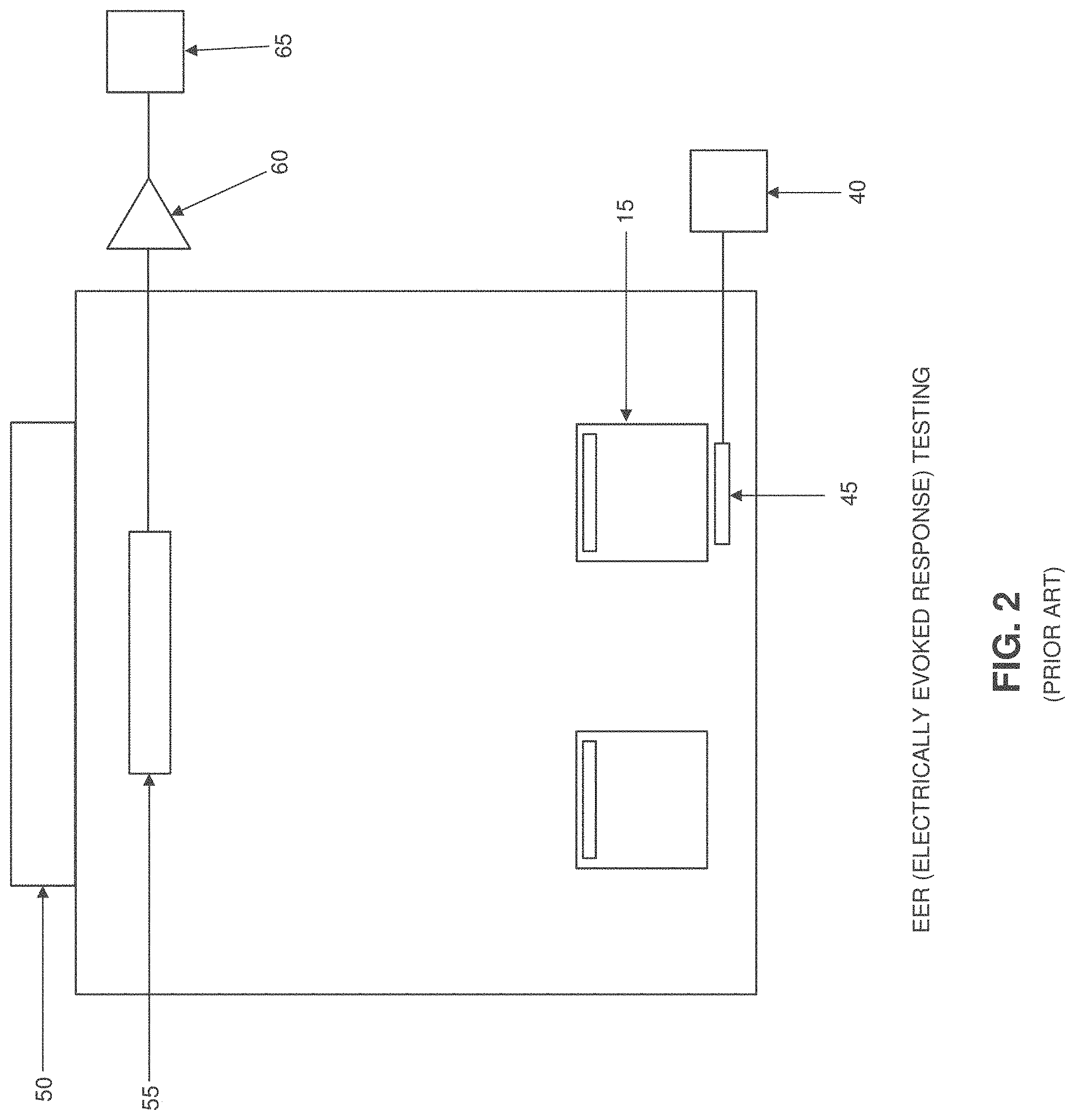
[0030] FIG. 2 is a schematic view showing a prior art EER system;
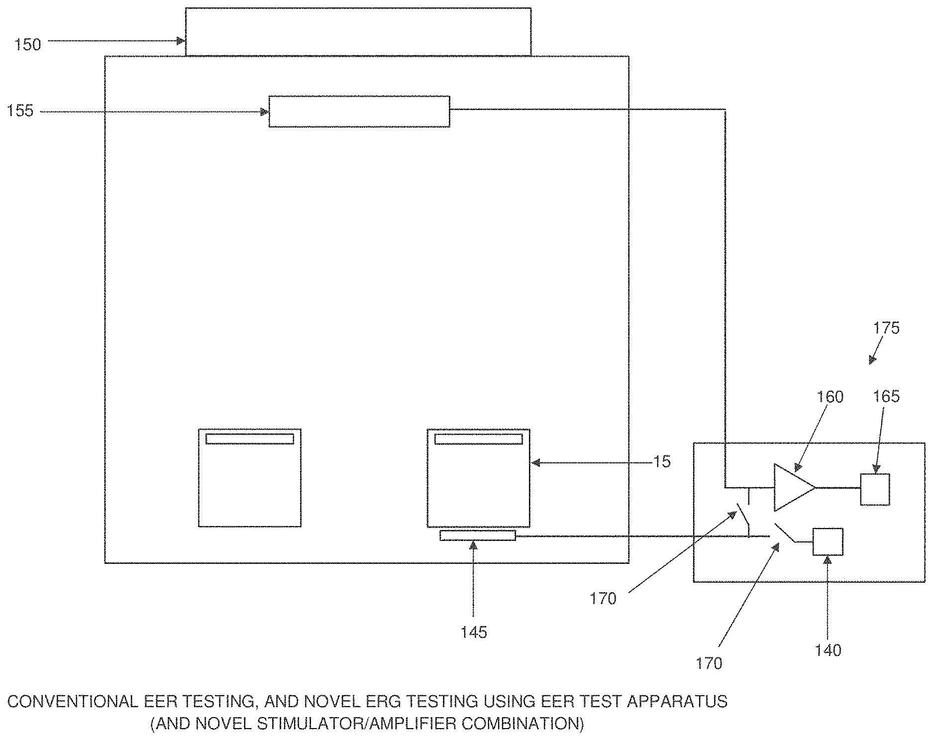
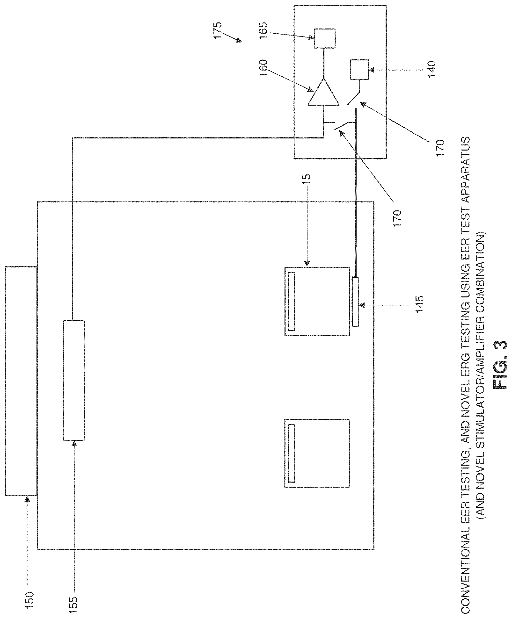
[0031] FIG. 3 is a schematic view showing a novel system formed in accordance with the present invention which can be used for conventional EER testing, and novel ERG testing using novel EER test apparatus (which includes a novel stimulator/amplifier combination); and
[0032] FIG. 4 is a schematic view showing an exemplary system formed in accordance with the present invention which can be used for conventional EER testing, and novel ERG testing using novel EER test apparatus (which includes a novel stimulator/amplifier combination).
DETAILED DESCRIPTION OF THE PREFERRED EMBODIMENTS
[0033] The present invention provides a novel EER stimulator which avoids the shortcomings associated with the prior art by being incorporated into a highly sensitive, highly linear 5-channel-32-bit medical amplifier. The novel EER stimulator/amplifier combination uses only standard amplifier connections to the patient to both deliver the electrical stimulus to the patient and to measure the response from the patient, enhancing ease-of-use, improving accuracy, and avoiding any possible harm to the patient that might result from the use of two unintegrated systems (i.e., stimulator and amplifier) with separate ground and control connections.
[0034] In addition to recording EER, the novel EER stimulator/amplifier combination is also capable of measuring an ERG response to an EER stimulus so as to assess retinal function. This capability is unique to the novel EER stimulator/amplifier combination of the present invention. More particularly, the EER system delivers the EER stimulus to the eye via a corneal electrode. In conventional systems, a second corneal electrode is required to measure the ERG response. Even if such an electrode were employed, however, the EER stimulus would be clipped by the input protection diodes of the amplifier reading the ERG response. These input protection diodes limit any voltage applied to their inputs to a value less than that required for effective EER stimulation. Consequently, the ERG response to a full EER stimulus cannot be measured using conventional equipment.
[0035] With the novel EER stimulator/amplifier combination of the present invention, the EER stimulator is isolated from the amplifier during EER stimulation by a fast-acting computer-controlled switch that can restore the amplifier connection as soon as the EER stimulus is complete. As a result, the full EER stimulus can be delivered to the cornea without amplifier clipping and, significantly, the same corneal electrode which is used to deliver the EER stimulation can also be used to detect the ERG response from the cornea. This arrangement also eliminates the need for a second corneal electrode in the same eye. In this way, the novel EER stimulator/amplifier combination of the present invention can measure both the retinal and the cortical response to an EER stimulus (i.e., the ERG and EER responses to an EER stimulus). This is not possible with conventional EER and ERG systems.
[0036] The integration of the EER stimulator with the data acquisition amplifier enhances both the safety and the accuracy of the EER stimulus. For example, it is possible to control the EER stimulus so that the current produced by the EER stimulator is completely symmetrical about the resting baseline patient voltage. This is important because otherwise the EER stimulator would impose, with each pulse, a DC potential across the patient which could ultimately result in plating electrode material into the eye. In order to ensure proper pulse symmetry, the current source should be monitored as it is applied to the patient. This is not possible unless the amplifier and the EER stimulator are closely integrated.
[0037] Another safety feature of this integration is that it permits the stimulus current to be measured both before and during its application to the patient. The hardware integrity can be checked prior to every pulse, and then confirmed during delivery. Measurement of the current pulse during stimulation confirms not only that the correct current is being delivered, but also verifies the integrity of the connections between device and patient, resulting in 100% verification that the correct stimulus has been applied.
[0038] Although the EER stimulus currents are applied only briefly to the patient, they exceed (by a large factor) the steady state leakage current allowed to be applied to a patient under ordinary conditions. For this reason it is important not only to control precisely the duration and amplitude of the applied currents, but also to ensure that the currents can neither be accidentally applied nor unintentionally be allowed to remain on. The integration of stimulator and amplifier facilitates this by making it practical to turn the power to the stimulator system completely off when it is not being used, and to limit the ground return current to a steady-state safe value (less than 10 .mu.A) at all times except during the stimulus pulse.
[0039] FIG. 1 shows a conventional ERG system. In such a system, a stimulator 5 drives a light source or a light pattern 10 so as to cause light to fall on an eye 15, whereby to induce an electrical response from the retina 20 of eye 15. This ERG electrical response is detected by a corneal electrode 25, measured by an amplifier 30 and then processed by a processor 35 so as to identify electrophysiological measures of visual function.
[0040] FIG. 2 shows a conventional EER system. In such a system, a stimulator 40 provides an electrical signal to a corneal electrode 45 positioned against an eye 15, whereby to induce an electrical response from the visual cortex 50. This EER electrical response is detected by scalp electrodes 55, measured by an amplifier 60 and then processed by a processor 65 so as to identify electrophysiological measures of visual function.
[0041] FIG. 3 shows a novel EER system formed in accordance with the present invention. In the novel EER system of the present invention, a stimulator 140 provides an electrical signal to a corneal electrode 145 positioned against an eye 15, whereby to induce an electrical response from the visual cortex 150. This EER electrical response is detected by scalp electrodes 155, measured by an amplifier 160 and then processed by a processor 165 so as to identify electrophysiological measures of visual function. In one preferred form of the invention, three scalp electrodes 155 are utilized.
[0042] In accordance with the present invention, the ERG electrical response to an EER stimulus may also be detected by corneal electrode 145. The ERG electrical response detected by corneal electrode 145 is measured by amplifier 160 and then processed by a processor 165 so as to identify electrophysiological measures of visual function. In order to prevent the EER stimulus from being clipped by the input protection diodes of the amplifier reading the ERG response, a fast-acting computer-controlled switch 170 can isolate the corneal electrode from the amplifier connection during application of the EER stimulation, and can restore the amplifier connection as soon as the EER stimulation is complete. In one preferred form of the invention, fast-acting computer-controlled switch 170 comprises a switch 170 disposed between the stimulator 140 and the corneal electrode 145, and a switch 170 disposed between the corneal electrode 145 and the amplifier 160. As a result, the full EER stimulus can be delivered to the cornea without amplifier clipping and, significantly, the same corneal electrode which is used to deliver the EER stimulation can also be used to detect the ERG response from the cornea.
[0043] It will be appreciated that the novel EER system of FIG. 3 comprises a novel electrically evoked response (EER) stimulator/amplifier combination 175.
[0044] FIG. 4 shows an exemplary novel electrically evoked response (EER) stimulator/amplifier combination 200 formed in accordance with the present invention. More particularly, exemplary novel electrically evoked response (EER) stimulator/amplifier combination 200 generally comprises (i) a stimulator 205 which generally comprises a power supply 210 and a Howland current source 215, (ii) an amplifier 220 which generally comprises a pair of operational amplifiers 225, and (iii) a CPU 230. Stimulator 205 is connected to amplifier 220 via a pair of switches 235 and a pair of switches 240. CPU 230 is connected to the Howland current source via a 16-bit DAC 245. Amplifier 220 is connected to CPU 230 via a Level Shifter 250 and an Analog-to-Digital Converter (ADC) 255. CPU 230 is connected to a Watchdog 260 which essentially comprises a timer which resets periodically and which shuts down the system if it does not receive its periodic reset (i.e., by connecting the low impedance ground of the power supply to the current-limited patient ground).
[0045] The exemplary novel electrically evoked response (EER) stimulator/amplifier combination 200 shown in FIG. 4 is intended to operate as follows:
[0046] 1. CPU output (Control A) and current source (Control E) are grounded.
[0047] 2. The EER power supply (Control B) is turned on.
[0048] 3. The ADC is zeroed.
[0049] 4. The current source (Control E) is ungrounded.
[0050] 5. Positive DAC current (Bus C) is written and ADC current (Bus D) is read to confirm positive current is correct.
[0051] 6. Negative DAC current (Bus C) is written and ADC current (Bus D) is read to confirm negative current is correct.
[0052] 7. DAC current (Bus C) is written to zero.
[0053] 8. Strobing of low impedance ground watchdog (Control E) begins.
[0054] 9. There is a 2 millisecond delay.
[0055] 10. The Channel 1 or Channel 2 EER output switch is turned on and the amplifier ADC is disconnected from output (Control G or H).
[0056] 11. Output (Control A) is ungrounded.
[0057] 12. Current pulses are written as directed by protocol, finish by writing zero current to DAC (Control C).
[0058] 13. The EER current is disconnected from output pin (Control G or H).
[0059] 14. The EER output (Control A) and current source (Control E) are grounded.
[0060] 15. Strobing of low impedance ground watchdog (Control E) is discontinued.
[0061] 16. The power supply (Control B) is turned off.
Modifications of the Preferred Embodiments
[0062] It should be understood that many additional changes in the details, materials, steps and arrangements of parts, which have been herein described and illustrated in order to explain the nature of the present invention, may be made by those skilled in the art while still remaining within the principles and scope of the invention.
* * * * *
D00000
D00001
D00002
D00003
D00004
XML
uspto.report is an independent third-party trademark research tool that is not affiliated, endorsed, or sponsored by the United States Patent and Trademark Office (USPTO) or any other governmental organization. The information provided by uspto.report is based on publicly available data at the time of writing and is intended for informational purposes only.
While we strive to provide accurate and up-to-date information, we do not guarantee the accuracy, completeness, reliability, or suitability of the information displayed on this site. The use of this site is at your own risk. Any reliance you place on such information is therefore strictly at your own risk.
All official trademark data, including owner information, should be verified by visiting the official USPTO website at www.uspto.gov. This site is not intended to replace professional legal advice and should not be used as a substitute for consulting with a legal professional who is knowledgeable about trademark law.