Bipolar Forceps
Scheller; Gregg D. ; et al.
U.S. patent application number 16/573746 was filed with the patent office on 2020-01-23 for bipolar forceps. The applicant listed for this patent is Kogent Surgical, LLC. Invention is credited to John M. Schallert, Gregg D. Scheller.
| Application Number | 20200022750 16/573746 |
| Document ID | / |
| Family ID | 69162721 |
| Filed Date | 2020-01-23 |


View All Diagrams
| United States Patent Application | 20200022750 |
| Kind Code | A1 |
| Scheller; Gregg D. ; et al. | January 23, 2020 |
BIPOLAR FORCEPS
Abstract
A surgical instrument for electrosurgery having a first forceps arm, a first forceps jaw of the first forceps arm, a first conductor tip of the first forceps arm, a second forceps arm disposed opposite the first forceps arm, a second forceps jaw of the second forceps arm, the second forceps jaw disposed opposite the first forceps jaw, a second conductor tip of the second forceps arm, and the second conductor tip disposed opposite the first conductor tip. The first forceps arm includes a first forceps arm first thermal portion comprised of a first thermal material, and a first forceps arm second thermal portion comprised of a second thermal material. The second forceps arm includes a second forceps arm first thermal portion comprised of the first material, and a second forceps arm second thermal portion comprised of the second material. The first forceps arm and the second forceps arm are configured to transfer thermal energy away from the first conductor tip and second conductor tip at a rate sufficient to maintain the thermal energy of the first conductor tip and second conductor tip below a designated thermal threshold.
| Inventors: | Scheller; Gregg D.; (Wildwood, MO) ; Schallert; John M.; (Lake St. Louis, MO) | ||||||||||
| Applicant: |
|
||||||||||
|---|---|---|---|---|---|---|---|---|---|---|---|
| Family ID: | 69162721 | ||||||||||
| Appl. No.: | 16/573746 | ||||||||||
| Filed: | September 17, 2019 |
Related U.S. Patent Documents
| Application Number | Filing Date | Patent Number | ||
|---|---|---|---|---|
| 16284324 | Feb 25, 2019 | |||
| 16573746 | ||||
| 15697930 | Sep 7, 2017 | |||
| 16284324 | ||||
| 15242696 | Aug 22, 2016 | 9801680 | ||
| 15697930 | ||||
| 14694659 | Apr 23, 2015 | 9452012 | ||
| 15242696 | ||||
| 13742120 | Jan 15, 2013 | 9044242 | ||
| 14694659 | ||||
| Current U.S. Class: | 1/1 |
| Current CPC Class: | A61B 2018/00589 20130101; A61B 2018/00595 20130101; A61B 2018/1462 20130101; A61B 18/1442 20130101; A61B 2018/00083 20130101; A61B 17/2909 20130101; A61B 2018/00095 20130101; A61B 2018/0063 20130101; A61B 18/1445 20130101; A61B 2018/00107 20130101; A61B 2017/00738 20130101 |
| International Class: | A61B 18/14 20060101 A61B018/14; A61B 17/29 20060101 A61B017/29 |
Claims
1. A surgical instrument for electrosurgery, comprising: a first forceps arm having a first forceps arm distal end and a first forceps arm proximal end; a first forceps jaw of the first forceps arm having a first forceps jaw distal end and a first forceps jaw proximal end wherein the first forceps jaw distal end is the first forceps arm distal end; a first conductor tip of the first forceps arm having a first conductor tip distal end and a first conductor tip proximal end wherein the first conductor tip distal end is the first forceps arm distal end and the first forceps jaw distal end and wherein the first conductor tip proximal end is disposed between the first forceps jaw proximal end and the first forceps arm distal end; a second forceps arm having a second forceps arm distal end and a second forceps arm proximal end, the second forceps arm disposed opposite the first forceps arm; a second forceps jaw of the second forceps arm having a second forceps jaw distal end and a second forceps jaw proximal end, the second forceps jaw disposed opposite the first forceps jaw wherein the second forceps jaw distal end is the second forceps arm distal end; a second conductor tip of the second forceps arm having a second conductor tip distal end and a second conductor tip proximal end, the second conductor tip disposed opposite the first conductor tip wherein the second conductor tip distal end is the second forceps arm distal end and the second forceps jaw distal end and wherein the second conductor tip proximal end is disposed between the second forceps jaw proximal end and the second forceps arm distal end; wherein the first forceps arm includes a first forceps arm first thermal portion comprised of a first thermal material, and a first forceps arm second thermal portion comprised of a second thermal material; wherein the second forceps arm includes a second forceps arm first thermal portion comprised of the first material, and a second forceps arm second thermal portion comprised of the second material; and wherein the first forceps arm and the second forceps arm are configured to transfer thermal energy away from the first conductor tip and second conductor tip at a rate sufficient to maintain the thermal energy of the first conductor tip and second conductor tip below a designated thermal threshold.
2. The surgical instrument of claim 1, wherein the first forceps arm first thermal portion operatively connects to the second forceps arm second thermal portion at a first thermal interface.
3. The surgical instrument of claim 1, wherein the first forceps arm first thermal portion comprises a copper alloy.
4. The surgical instrument of claim 1, wherein the second forceps arm first thermal portion comprises a copper alloy.
5. The surgical instrument of claim 1, wherein the first forceps arm second thermal portion comprises a aluminum.
6. The surgical instrument of claim 1, wherein the second forceps arm second thermal portion comprises an aluminum alloy.
7. The surgical instrument of claim 1, wherein the first thermal material comprises a material having a thermal conductivity higher than about 200 W/m K.
8. The surgical instrument of claim 1, further comprising a plating layer covering at least a portion of the first conductor tip of the first forceps arm.
9. The surgical instrument of claim 8, wherein the plating layer comprises a silver alloy.
10. The surgical instrument of claim 8, the plating layer being deposited directly to an outer surface of at least the portion of the first conductor tip.
11. The surgical instrument of claim 1, further comprising a plating layer covering at least a portion of the second conductor tip of the first forceps arm.
12. The surgical instrument of claim 11, wherein the plating layer comprises a silver alloy.
13. The surgical instrument of claim 11, the plating layer being deposited directly to an outer surface of at least the portion of the second conductor tip.
14. The surgical instrument of claim 1, further comprising a coating of an electrical insulator material over at least a portion of the first forceps arm and at least a portion of the second forceps arm.
15. The surgical instrument of claim 1, wherein the surgical instrument is configured to be disposable.
16. The surgical instrument of claim 1, further comprising a first forceps arm aperture of the first forceps arm, wherein the first forceps arm aperture is configured to reduce a mass of the first forceps arm; and wherein the second forceps arm aperture is configured to reduce a mass of the second forceps arm.
17. A surgical instrument for electrosurgery, comprising: a first forceps arm having a first forceps arm distal end and a first forceps arm proximal end; a first forceps jaw of the first forceps arm having a first forceps jaw distal end and a first forceps jaw proximal end wherein the first forceps jaw distal end is the first forceps arm distal end; a first conductor tip of the first forceps arm having a first conductor tip distal end and a first conductor tip proximal end wherein the first conductor tip distal end is the first forceps arm distal end and the first forceps jaw distal end and wherein the first conductor tip proximal end is disposed between the first forceps jaw proximal end and the first forceps arm distal end, the first conductor tip having a first plating layer deposited directly to at least a portion of an outer surface of the first conductor tip; a second forceps arm having a second forceps arm distal end and a second forceps arm proximal end, the second forceps arm disposed opposite the first forceps arm; a second forceps jaw of the second forceps arm having a second forceps jaw distal end and a second forceps jaw proximal end, the second forceps jaw disposed opposite the first forceps jaw wherein the second forceps jaw distal end is the second forceps arm distal end; a second conductor tip of the second forceps arm having a second conductor tip distal end and a second conductor tip proximal end, the second conductor tip disposed opposite the first conductor tip wherein the second conductor tip distal end is the second forceps arm distal end and the second forceps jaw distal end and wherein the second conductor tip proximal end is disposed between the second forceps jaw proximal end and the second forceps arm distal end, the second conductor tip having a second plating layer deposited directly to at least a portion of an outer surface of the second conductor tip; and wherein the first forceps arm and the second forceps arm are configured to transfer thermal energy away from the first conductor tip and second conductor tip at a rate sufficient to maintain the thermal energy of the first conductor tip and second conductor tip below a designated thermal threshold.
18. The surgical instrument of claim 13, wherein the first plating layer and the second plating layer comprise a silver alloy.
19. The surgical instrument of claim 13, further comprising a coating of an electrical insulator material over at least a portion of the first forceps arm and at least a portion of the second forceps arm.
20. A method of manufacturing a surgical instrument, comprising: providing a first forceps arm having a first forceps arm distal end and a first forceps arm proximal end; providing a first forceps jaw of the first forceps arm having a first forceps jaw distal end and a first forceps jaw proximal end wherein the first forceps jaw distal end is the first forceps arm distal end; providing a first conductor tip of the first forceps arm having a first conductor tip distal end and a first conductor tip proximal end wherein the first conductor tip distal end is the first forceps arm distal end and the first forceps jaw distal end and wherein the first conductor tip proximal end is disposed between the first forceps jaw proximal end and the first forceps arm distal end; providing a second forceps arm having a second forceps arm distal end and a second forceps arm proximal end, the second forceps arm disposed opposite the first forceps arm; providing a second forceps jaw of the second forceps arm having a second forceps jaw distal end and a second forceps jaw proximal end, the second forceps jaw disposed opposite the first forceps jaw wherein the second forceps jaw distal end is the second forceps arm distal end; providing a second conductor tip of the second forceps arm having a second conductor tip distal end and a second conductor tip proximal end, the second conductor tip disposed opposite the first conductor tip wherein the second conductor tip distal end is the second forceps arm distal end and the second forceps jaw distal end and wherein the second conductor tip proximal end is disposed between the second forceps jaw proximal end and the second forceps arm distal end; and depositing a first plating layer directly onto at least a portion of a first outer surface of the first conductor tip; depositing a second plating layer directly onto at least a portion of a second outer surface of the second conductor tip; wherein the first forceps arm includes a first forceps arm first thermal portion comprised of a first thermal material, and a first forceps arm second thermal portion comprised of a second thermal material; wherein the second forceps arm includes a second forceps arm first thermal portion comprised of the first material, and a second forceps arm second thermal portion comprised of the second material; and wherein the first forceps arm and the second forceps arm are configured to transfer thermal energy away from the first conductor tip and second conductor tip at a rate sufficient to maintain the thermal energy of the first conductor tip and second conductor tip below a designated thermal threshold.
Description
CROSS-REFERENCE TO RELATED APPLICATIONS
[0001] This Application is a continuation-in-part of prior application Ser. No. 16/284,324, filed Feb. 25, 2019, which is a continuation-in-part of prior application Ser. No. 15/697,930 filed Sep. 7, 2017, which is a continuation of U.S. Pat. No. 9,801,680, filed Aug. 22, 2016, which is a continuation of U.S. Pat. No. 9,452,012, filed Apr. 23, 2015, which is a continuation of U.S. Pat. No. 9,044,242, filed Jan. 15, 2013, the entire disclosure of which are incorporated herein by reference.
STATEMENT REGARDING FEDERALLY SPONSORED RESEARCH
[0002] Not applicable.
BACKGROUND
[0003] The present disclosure relates to a surgical instrument, and, more particularly, to a bipolar forceps for electrosurgery.
[0004] A variety of surgical procedures may be performed using electrosurgery with a bipolar forceps, including, but not limited to, neurosurgical, spinal, dermatological, gynecological, cardiac, plastic, ocular, maxillofacial, orthopedic, urological, and general surgical procedures. Generally, electrosurgery is performed by applying a high-frequency electrical current to a targeted area of biological tissue to cut or coagulate the tissue. Typically, a bipolar forceps includes an active electrode and a return electrode operatively connected to a power source of high-frequency electrical current. In operation, the high-frequency electrical current flows out from the active electrode, through the targeted area of biological tissue, and into the return electrode. The flow of high-electrical current through the targeted area of biological tissue cuts and/or coagulates the tissue. During this process, thermal energy, such as heat, is created at the point of application, such as the targeted area of biological tissue, and then transferred to the arms or tips of the bipolar forceps. In particular, repeated or extended use of the bipolar forceps can result in increased thermal energy which often results in the bipolar forceps charring or sticking to biological tissue. When bipolar forceps stick to cauterized tissue, surgeons must spend time separating the tips from the tissue, which can result in rebleeding of the cauterized tissue. In addition, the thermal energy may undesirably damage or char non-targeted biological tissue in proximity to the targeted area of biological tissue. During operation, surgeons may rely on visual cues to indicate the amount and degree of damage to biological tissue. For example, it is preferable to see a visual indication of "white" coagulation, which indicates decreased tissue damage, as opposed to "black" coagulation, which indicates increased tissue damage.
[0005] Typically, bipolar forceps include non-stick materials covering the electrodes to reduce the tendency of sticking to biological tissue. However, even the use of such non-stick materials does not completely prevent the sticking and charring of biological tissue, especially during procedures that require extended and repeated use. In such procedures, conventional bipolar forceps are not capable of transferring thermal energy away from the electrodes at a sufficient rate to prevent the electrodes from heating up and reaching a threshold of thermal energy that causes sticking and charring of biological tissue. In addition, the application of non-stick materials to the bipolar forceps increases cost and time of manufacturing. For example, the process of applying non-stick materials typically involves multiple steps of plating multiple materials. Cost is an important design criteria in the manufacture of bipolar forceps, and in particular for the manufacture of disposable bipolar forceps.
[0006] Therefore, there is a need for a cost-effective bipolar forceps with a high thermal transfer rate to prevent damage to biological tissue during electrosurgery.
BRIEF DESCRIPTION
[0007] In one embodiment, a surgical instrument for electrosurgery is provided that includes a first forceps arm having a first forceps arm distal end and a first forceps arm proximal end, a first forceps jaw of the first forceps arm having a first forceps jaw distal end and a first forceps jaw proximal end wherein the first forceps jaw distal end is the first forceps arm distal end, a first conductor tip of the first forceps arm having a first conductor tip distal end and a first conductor tip proximal end wherein the first conductor tip distal end is the first forceps arm distal end and the first forceps jaw distal end and wherein the first conductor tip proximal end is disposed between the first forceps jaw proximal end and the first forceps arm distal end, a second forceps arm having a second forceps arm distal end and a second forceps arm proximal end, the second forceps arm disposed opposite the first forceps arm, a second forceps jaw of the second forceps arm having a second forceps jaw distal end and a second forceps jaw proximal end, the second forceps jaw disposed opposite the first forceps jaw wherein the second forceps jaw distal end is the second forceps arm distal end, a second conductor tip of the second forceps arm having a second conductor tip distal end and a second conductor tip proximal end, the second conductor tip disposed opposite the first conductor tip wherein the second conductor tip distal end is the second forceps arm distal end and the second forceps jaw distal end and wherein the second conductor tip proximal end is disposed between the second forceps jaw proximal end and the second forceps arm distal end, wherein the first forceps arm includes a first forceps arm first thermal portion comprised of a first thermal material, and a first forceps arm second thermal portion comprised of a second thermal material, wherein the second forceps arm includes a second forceps arm first thermal portion comprised of the first material, and a second forceps arm second thermal portion comprised of the second material, and wherein the first forceps arm and the second forceps arm are configured to transfer thermal energy away from the first conductor tip and second conductor tip at a rate sufficient to maintain the thermal energy of the first conductor tip and second conductor tip below a designated thermal threshold.
[0008] In another embodiment, a surgical instrument for electrosurgery includes a first forceps arm having a first forceps arm distal end and a first forceps arm proximal end, a first forceps jaw of the first forceps arm having a first forceps jaw distal end and a first forceps jaw proximal end wherein the first forceps jaw distal end is the first forceps arm distal end, a first conductor tip of the first forceps arm having a first conductor tip distal end and a first conductor tip proximal end wherein the first conductor tip distal end is the first forceps arm distal end and the first forceps jaw distal end and wherein the first conductor tip proximal end is disposed between the first forceps jaw proximal end and the first forceps arm distal end, the first conductor tip having a first plating layer deposited directly to at least a portion of an outer surface of the first conductor tip, a second forceps arm having a second forceps arm distal end and a second forceps arm proximal end, the second forceps arm disposed opposite the first forceps arm, a second forceps jaw of the second forceps arm having a second forceps jaw distal end and a second forceps jaw proximal end, the second forceps jaw disposed opposite the first forceps jaw wherein the second forceps jaw distal end is the second forceps arm distal end, a second conductor tip of the second forceps arm having a second conductor tip distal end and a second conductor tip proximal end, the second conductor tip disposed opposite the first conductor tip wherein the second conductor tip distal end is the second forceps arm distal end and the second forceps jaw distal end and wherein the second conductor tip proximal end is disposed between the second forceps jaw proximal end and the second forceps arm distal end, the second conductor tip having a second plating layer deposited directly to at least a portion of an outer surface of the second conductor tip, and wherein the first forceps arm and the second forceps arm are configured to transfer thermal energy away from the first conductor tip and second conductor tip at a rate sufficient to maintain the thermal energy of the first conductor tip and second conductor tip below a designated thermal threshold.
[0009] In another embodiment, a method of manufacturing a surgical instrument includes providing a first forceps arm having a first forceps arm distal end and a first forceps arm proximal end, providing a first forceps jaw of the first forceps arm having a first forceps jaw distal end and a first forceps jaw proximal end wherein the first forceps jaw distal end is the first forceps arm distal end, providing a first conductor tip of the first forceps arm having a first conductor tip distal end and a first conductor tip proximal end wherein the first conductor tip distal end is the first forceps arm distal end and the first forceps jaw distal end and wherein the first conductor tip proximal end is disposed between the first forceps jaw proximal end and the first forceps arm distal end, providing a second forceps arm having a second forceps arm distal end and a second forceps arm proximal end, the second forceps arm disposed opposite the first forceps arm, providing a second forceps jaw of the second forceps arm having a second forceps jaw distal end and a second forceps jaw proximal end, the second forceps jaw disposed opposite the first forceps jaw wherein the second forceps jaw distal end is the second forceps arm distal end, providing a second conductor tip of the second forceps arm having a second conductor tip distal end and a second conductor tip proximal end, the second conductor tip disposed opposite the first conductor tip wherein the second conductor tip distal end is the second forceps arm distal end and the second forceps jaw distal end and wherein the second conductor tip proximal end is disposed between the second forceps jaw proximal end and the second forceps arm distal end, depositing a first plating layer directly onto at least a portion of a first outer surface of the first conductor tip, depositing a second plating layer directly onto at least a portion of a second outer surface of the second conductor tip, wherein the first forceps arm includes a first forceps arm first thermal portion comprised of a first thermal material, and a first forceps arm second thermal portion comprised of a second thermal material, herein the second forceps arm includes a second forceps arm first thermal portion comprised of the first material, and a second forceps arm second thermal portion comprised of the second material, and wherein the first forceps arm and the second forceps arm are configured to transfer thermal energy away from the first conductor tip and second conductor tip at a rate sufficient to maintain the thermal energy of the first conductor tip and second conductor tip below a designated thermal threshold.
BRIEF DESCRIPTION OF THE DRAWINGS
[0010] The present inventive subject matter will be better understood from reading the following description of non-limiting embodiments, with reference to the attached drawings, wherein below:
[0011] FIG. 1 is a schematic diagram illustrating a side view of a forceps arm;
[0012] FIG. 2 is a schematic diagram illustrating an exploded view of a bipolar forceps assembly;
[0013] FIGS. 3A, 3B, 3C, 3D, and 3E are schematic diagrams illustrating a gradual closing of a bipolar forceps;
[0014] FIGS. 4A, 4B, 4C, 4D, and 4E are schematic diagrams illustrating a gradual opening of a bipolar forceps;
[0015] FIGS. 5A, 5B, and 5C are schematic diagrams illustrating a uniform compression of a vessel.
[0016] FIG. 6 is a side view of an alternate embodiment of a forceps arm;
[0017] FIG. 7A is a partial side view of the alternate embodiment of the forceps arm;
[0018] FIG. 7B is a partial exploded view of the alternate embodiment of the forceps arm
[0019] FIG. 8 is a top view of the alternate embodiment of the forceps arm;
[0020] FIG. 9 is an enlarged top view of the alternate embodiment of the forceps arm.
[0021] Corresponding reference numerals indicate corresponding parts throughout the several figures of the drawings.
DETAILED DESCRIPTION
[0022] The following detailed description illustrates the inventive subject matter by way of example and not by way of limitation. The description enables one of ordinary skill in the art to make and use the inventive subject matter, describes several embodiments of the inventive subject matter, as well as adaptations, variations, alternatives, and uses of the inventive subject matter. Additionally, it is to be understood that the inventive subject matter is not limited in its application to the details of construction and the arrangements of components set forth in the following description or illustrated in the drawings. The inventive subject matter is capable of other embodiments and of being practiced or being carried out in various ways. Also, it is to be understood that the phraseology and terminology used herein is for the purpose of description and should not be regarded as limiting on all embodiments of the inventive subject matter.
[0023] The terminology used herein is for the purpose of describing particular exemplary embodiments only and is not intended to be limiting. As used herein, the singular forms "a", "an" and "the" may be intended to include the plural forms as well, unless the context clearly indicates otherwise. The terms "comprises," "comprising," "including," and "having," are inclusive and therefore specify the presence of stated features, integers, steps, operations, elements, and/or components, but do not preclude the presence or addition of one or more other features, integers, steps, operations, elements, components, and/or groups thereof. The steps, processes, and operations described herein are not to be construed as necessarily requiring their respective performance in the particular order discussed or illustrated, unless specifically identified as a preferred order of performance. It is also to be understood that additional or alternative steps may be employed.
[0024] FIG. 1 is a schematic diagram illustrating a side view of a forceps arm 100. Illustratively, a forceps arm 100 may comprise an input conductor housing 103, a forceps arm aperture 105, a conductor tip 110, a forceps arm superior incline angle 120, a forceps arm inferior decline angle 125, a forceps arm superior decline angle 130, a forceps arm inferior incline angle 135, a socket interface 140, a forceps arm grip 150, a forceps jaw 160, and a forceps jaw taper interface 170. In one or more embodiments, forceps arm 100 may be manufactured from any suitable material, e.g., polymers, metals, metal alloys, etc., or from any combination of suitable materials. Illustratively, forceps arm 100 may be manufactured from an electrically conductive material, e.g., metal, graphite, conductive polymers, etc. In one or more embodiments, forceps arm 100 may be manufactured from an electrically conductive metal, e.g., silver, copper, gold, aluminum, etc. Illustratively, forceps arm 100 may be manufactured from an electrically conductive metal alloy, e.g., a silver alloy, a copper alloy, a gold alloy, an aluminum alloy, stainless steel, etc.
[0025] In one or more embodiments, forceps arm 100 may be manufactured from a material having an electrical conductivity in a range of 30.0.times.106 to 40.0.times.106 Siemens per meter at a temperature of 20.0.degree. C., e.g., forceps arm 100 may be manufactured from a material having an electrical conductivity of 35.5.times.106 Siemens per meter at a temperature of 20.0.degree. C. Illustratively, forceps arm 100 may be manufactured from a material having an electrical conductivity of less than 30.0.times.106 Siemens per meter or greater than 40.0.times.106 Siemens per meter at a temperature of 20.0.degree. C. In one or more embodiments, forceps arm 100 may be manufactured from a material having a thermal conductivity in a range of 180.0 to 250.0 Watts per meter Kelvin at a temperature of 20.0.degree. C., e.g., forceps arm 100 may be manufactured from a material having a thermal conductivity of 204.0 Watts per meter Kelvin at a temperature of 20.0.degree. C. Illustratively, forceps arm 100 may be manufactured from a material having a thermal conductivity of less than 180.0 Watts per meter Kelvin or greater than 250.0 Watts per meter Kelvin at a temperature of 20.0.degree. C. In one or more embodiments, forceps arm 100 may be manufactured from a material having an electrical conductivity in a range of 30.0.times.106 to 40.0.times.106 Siemens per meter and a thermal conductivity in a range of 180.0 to 250.0 Watts per meter Kelvin at a temperature of 20.0.degree. C., e.g., forceps arm 100 may be manufactured from a material having an electrical conductivity of 35.5.times.106 Siemens per meter and a thermal conductivity of 204.0 Watts per meter Kelvin at a temperature of 20.0.degree. C.
[0026] Illustratively, forceps arm 100 may have a density in a range of 0.025 to 0.045 pounds per cubic inch, e.g., forceps arm 100 may have a density of 0.036 pounds per cubic inch. In one or more embodiments, forceps arm 100 may have a density less than 0.025 pounds per cubic inch or greater than 0.045 pounds per cubic inch. For example, forceps arm 100 may have a density of 0.0975 pounds per cubic inch. Illustratively, forceps arm 100 may have a mass in a range of 0.01 to 0.025 pounds, e.g., forceps arm 100 may have a mass of 0.017 pounds. In one or more embodiments, forceps arm 100 may have a mass less than 0.01 pounds or greater than 0.025 pounds. Illustratively, forceps arm 100 may have a volume in a range of 0.12 to 0.23 cubic inches, e.g., forceps arm 100 may have a volume of 0.177 cubic inches. In one or more embodiments, forceps arm 100 may have a volume less than 0.12 cubic inches or greater than 0.23 cubic inches. Illustratively, forceps arm aperture 105 may be configured to reduce a stiffness of forceps arm 100. In one or more embodiments, forceps arm aperture 105 may be configured to increase a flexibility of forceps arm 100.
[0027] Illustratively, forceps arm aperture 105 may be configured to reduce a mass of forceps arm 100. In one or more embodiments, forceps arm aperture 105 may be configured to reduce a mass of forceps arm 100 by an avoided mass in a range of 0.005 to 0.012 pounds, e.g., forceps arm aperture 105 may be configured to reduce a mass of forceps arm 100 by an avoided mass of 0.00975 pounds. Illustratively, forceps arm aperture 105 may be configured to reduce a mass of forceps arm 100 by an avoided mass less than 0.005 pounds or greater than 0.012 pounds. In one or more embodiments, forceps arm aperture 105 may have an aperture area in a range of 0.3 to 0.65 square inches, e.g., forceps arm aperture 105 may have an aperture area of 0.485 square inches. Illustratively, forceps arm aperture 105 may have an aperture area less than 0.3 square inches or greater than 0.65 square inches. In one or more embodiments, forceps arm aperture 105 may have an aperture perimeter length in a range of 4.0 to 7.0 inches, e.g., forceps arm aperture 105 may have an aperture perimeter length of 5.43 inches. Illustratively, forceps arm aperture 105 may have an aperture perimeter length less than 4.0 inches or greater than 7.0 inches.
[0028] In one or more embodiments, forceps arm aperture 105 may be configured to decrease a thermal conductivity of forceps arm grip 150. Illustratively, forceps arm aperture 105 may be configured to decrease an electrical conductivity of forceps arm grip 150. In one or more embodiments, forceps arm aperture 105 may be configured to decrease a thermal conductivity and to decrease an electrical conductivity of forceps arm grip 150. Illustratively, forceps arm aperture 105 may be configured to reduce a probability that forceps arm grip 150 may reach a temperature of 48.89.degree. C. during a surgical procedure. In one or more embodiments, forceps arm aperture 105 may be configured to reduce a probability that forceps arm grip 150 may reach a temperature of 48.89.degree. C. during a surgical procedure, e.g., by decreasing a thermal conductivity of forceps arm grip 150. Illustratively, forceps arm aperture 105 may be configured to reduce a probability that forceps arm grip 150 may reach a temperature of 48.89.degree. C. during a surgical procedure, e.g., by decreasing an electrical conductivity of forceps arm grip 150. In one or more embodiments, forceps arm aperture 105 may be configured to reduce a probability that forceps arm grip 150 may reach a temperature of 48.89.degree. C. during a surgical procedure, e.g., by decreasing a thermal conductivity and an electrical conductivity of forceps arm grip 150.
[0029] Illustratively, forceps arm 100 may have a surface area in a range of 4.5 to 7.5 square inches, e.g., forceps arm 100 may have a surface area of 6.045 square inches. In one or more embodiments, forceps arm 100 may have a surface area less than 4.5 square inches or greater than 7.5 square inches. Illustratively, conductor tip 110 may have a surface area in a range of 0.02 to 0.05 square inches, e.g., conductor tip 110 may have a surface area of 0.035 square inches. In one or more embodiments, conductor tip 110 may have a surface area less than 0.02 square inches or greater than 0.05 square inches. Illustratively, a ratio of forceps arm 100 surface area to conductor tip 110 surface area may be in a range of 150.0 to 225.0, e.g., a ratio of forceps arm 100 surface area to conductor tip 110 surface area may be 172.7. In one or more embodiments, a ratio of forceps arm 100 surface area to conductor tip 110 surface area may be less than 150.0 or greater than 225.0.
[0030] Illustratively, conductor tip 110 may be configured to prevent tissue from sticking to conductor tip 110. In one or more embodiments, conductor tip 110 may comprise a evenly polished material configured to prevent tissue sticking. Illustratively, conductor tip 110 may have a length in a range of 0.22 to 0.3 inches, e.g., conductor tip 110 may have a length of 0.26 inches. In one or more embodiments, conductor tip 110 may have a length less than 0.22 inches or greater than 0.3 inches. Illustratively, conductor tip 110 may have a width in a range of 0.03 to 0.05 inches, e.g., conductor tip 110 may have a width of 0.04 inches. In one or more embodiments, conductor tip 110 may have a width less than 0.03 inches or greater than 0.05 inches. Illustratively, a geometry of forceps jaw 160 may comprise a tapered portion, e.g., a tapered portion from forceps jaw taper interface 170 to forceps arm distal end 101. In one or more embodiments, forceps jaw 160 may comprise a tapered portion having a tapered angle in a range of 3.0 to 4.5 degrees, e.g., forceps jaw 160 may comprise a tapered portion having a tapered angle of 3.72 degrees. Illustratively, forceps jaw 160 may comprise a tapered portion having a tapered angle of less than 3.0 degrees or greater than 4.5 degrees.
[0031] Illustratively, forceps arm 100 may comprise a material having a modulus of elasticity in a range of 9.0.times.106 to 11.0.times.106 pounds per square inch, e.g., forceps arm 100 may comprise a material having a modulus of elasticity of 10.0.times.106 pounds per square inch. In one or more embodiments, forceps arm 100 may comprise a material having a modulus of elasticity less than 9.0.times.106 pounds per square inch or greater than 11.0.times.106 pounds per square inch. Illustratively, forceps arm 100 may comprise a material having a shear modulus in a range of 3.5.times.106 to 4.5.times.106 pounds per square inch, e.g., forceps arm 100 may comprise a material having a shear modulus of 3.77.times.106 pounds per square inch. In one or more embodiments, forceps arm 100 may comprise a material having a shear modulus less than 3.5.times.106 pounds per square inch or greater than 4.5.times.106 pounds per square inch.
[0032] Illustratively, forceps arm superior incline angle 120 may comprise any angle greater than 90.0 degrees. In one or more embodiments, forceps arm superior incline angle 120 may comprise any angle in a range of 150.0 to 170.0 degrees, e.g., forceps arm superior incline angle 120 may comprise a 160.31 degree angle. Illustratively, forceps arm superior incline angle 120 may comprise an angle less than 150.0 degrees or greater than 170.0 degrees. In one or more embodiments, forceps arm inferior decline angle 125 may comprise any angle greater than 90.0 degrees. Illustratively, forceps arm inferior decline angle 125 may comprise any angle in a range of 140.0 to 160.0 degrees, e.g., forceps arm inferior decline angle 125 may comprise a 149.56 degree angle. In one or more embodiments, forceps arm inferior decline angle 125 may comprise an angle less than 140.0 degrees or greater than 160.0 degrees. Illustratively, forceps arm inferior decline angle 125 may comprise any angle less than forceps arm superior incline angle 120, e.g., forceps arm inferior decline angle 125 may comprise an angle in a range of 5.0 to 15.0 degrees less than forceps arm superior incline angle 120. In one or more embodiments, forceps arm inferior decline angle 125 may comprise an angle less than 5.0 degrees or greater than 15.0 degrees less than forceps arm superior incline angle 120.
[0033] Illustratively, forceps arm superior decline angle 130 may comprise any angle less than 90.0 degrees. In one or more embodiments, forceps arm superior decline angle 130 may comprise any angle in a range of 5.0 to 15.0 degrees, e.g., forceps arm superior decline angle 130 may comprise an 11.3 degree angle. Illustratively, forceps arm superior decline angle 130 may comprise an angle less than 5.0 degrees or greater than 15.0 degrees. In one or more embodiments, forceps arm inferior incline angle 135 may comprise any angle less than 90.0 degrees. Illustratively, forceps arm inferior incline angle 135 may comprise any angle in a range of 15.0 to 30.0 degrees, e.g., forceps arm inferior incline angle 135 may comprise a 23.08 degree angle. In one or more embodiments, forceps arm inferior incline angle 135 may comprise an angle less than 15.0 degrees or greater than 30.0 degrees. Illustratively, forceps arm inferior incline angle 135 may comprise any angle greater than forceps arm superior decline angle 130, e.g., forceps arm inferior incline angle 135 may comprise an angle in a range of 5.0 to 15.0 degrees greater than forceps arm superior decline angle 130. In one or more embodiments, forceps arm inferior incline angle 135 may comprise an angle less than 5.0 degrees or greater than 15.0 degrees greater than forceps arm superior decline angle 130.
[0034] FIG. 2 is a schematic diagram illustrating an exploded view of a bipolar forceps assembly 200. In one or more embodiments, a bipolar forceps assembly 200 may comprise a pair of forceps arms 100, an input conductor isolation mechanism 210, a bipolar cord 220, a bipolar cord separation control 230, and an electrosurgical generator adaptor 240. Illustratively, a portion of each forceps arm 100 may be coated with a material having a high electrical resistivity, e.g., a portion of each forceps arm 100 may be coated with an electrical insulator material. In one or more embodiments, input conductor housings 103 and conductor tips 110 may not be coated with a material, e.g., input conductor housings 103 and conductor tips 110 may comprise electrical leads. Illustratively, a portion of each forceps arm 100 may be coated with a thermoplastic material, e.g., a portion of each forceps arm 100 may be coated with nylon. In one or more embodiments, a portion of each forceps arm 100 may be coated with a fluoropolymer, e.g., a portion of each forceps arm 100 may be coated with polyvinylidene fluoride. Illustratively, a portion of each forceps arm 100 may be coated with a material having an electrical conductivity less than 1.0.times.10-8 Siemens per meter at a temperature of 20.0.degree. C., e.g., a portion of each forceps arm 100 may be coated with a material having an electrical conductivity of 1.0.times.10-12 Siemens per meter at a temperature of 20.0.degree. C. In one or more embodiments, a portion of each forceps arm 100 may be coated with a material having a thermal conductivity of less than 1.0 Watts per meter Kelvin at a temperature of 20.0.degree. C., e.g., a portion of each forceps arm 100 may be coated with a material having a thermal conductivity of 0.25 Watts per meter Kelvin at a temperature of 20.0.degree. C. Illustratively, a portion of each forceps arm 100 may be coated with a material having an electrical conductivity of less than 1.0.times.10-8 Siemens per meter and a thermal conductivity of less than 1.0 Watts per meter Kelvin at a temperature of 20.0.degree. C., e.g., a portion of each forceps arm 100 may be coated with a material having an electrical conductivity of 1.0.times.10-12 Siemens per meter and a thermal conductivity of 0.25 Watts per meter Kelvin at a temperature of 20.0.degree. C. In one or more embodiments, a portion of each forceps arm 100 may be coated with a material wherein a coating thickness of the material is in a range of 0.005 to 0.008 inches, e.g., a portion of each forceps arm 100 may be coated with a material wherein a coating thickness of the material is 0.0065 inches. Illustratively, a portion of each forceps arm 100 may be coated with a material wherein a coating thickness of the material is less than 0.005 inches or greater than 0.008 inches. In one or more embodiments, a portion of each forceps arm 100 may be coated with a material having an electrical conductivity of less than 1.0.times.10-8 Siemens per meter and a thermal conductivity of less than 1.0 Watts per meter Kelvin at a temperature of 20.0.degree. C. wherein a coating thickness of the material is in a range of 0.005 to 0.008 inches, e.g., a portion of each forceps arm 100 may be coated with a material having an electrical conductivity of 1.0.times.10-12 Siemens per meter and a thermal conductivity of 0.25 Watts per meter Kelvin at a temperature of 20.0.degree. C. wherein a coating thickness of the material is 0.0065 inches. Illustratively, a portion of each forceps arm 100 may be coated with a material having a material mass in a range of 0.0015 to 0.0025 pounds, e.g., a portion of each forceps arm 100 may be coated with a material having a material mass of 0.0021 pounds. In one or more embodiments, a portion of each forceps arm 100 may be coated with a material having a material mass less than 0.0015 pounds or greater than 0.0025 pounds.
[0035] Illustratively, input conductor isolation mechanism 210 may comprise a first forceps arm housing 215 and a second forceps arm housing 215. In one or more embodiments, input conductor isolation mechanism 210 may be configured to separate a first bipolar input conductor and a second bipolar input conductor, e.g., input conductor isolation mechanism 210 comprise a material with an electrical resistivity greater than 1.times.1016 ohm meters. Illustratively, input conductor isolation mechanism 210 may comprise a material with an electrical resistivity less than or equal to 1.times.1016 ohm meters. In one or more embodiments, input conductor isolation mechanism 210 may comprise an interface between bipolar cord 220 and forceps arms 100. Illustratively, a first bipolar input conductor and a second bipolar input conductor may be disposed within bipolar cord 220, e.g., bipolar cord 220 may be configured to separate the first bipolar input conductor and the second bipolar input conductor. In one or more embodiments, a first bipolar input conductor may be electrically connected to first forceps arm 100, e.g., the first bipolar input conductor may be disposed within input conductor housing 103. Illustratively, a second bipolar input conductor may be electrically connected to second forceps arm 100, e.g., the second bipolar input conductor may be disposed within input conductor housing 103. In one or more embodiments, a portion of first forceps arm 100 may be disposed within first forceps arm housing 215, e.g., first forceps arm proximal end 102 may be disposed within first forceps arm housing 215. Illustratively, first forceps arm 100 may be fixed within first forceps arm housing 215, e.g., by an adhesive or any suitable fixation means. In one or more embodiments, a first bipolar input conductor may be disposed within first forceps arm housing 215, e.g., the first bipolar input conductor may be electrically connected to first forceps arm 100. Illustratively, a first bipolar input conductor may be fixed within first forceps arm housing 215 wherein the first bipolar input conductor is electrically connected to first forceps arm 100. In one or more embodiments, a portion of second forceps arm 100 may be disposed within second forceps arm housing 215, e.g., second forceps arm proximal end 102 may be disposed within second forceps arm housing 215. Illustratively, second forceps arm 100 may be fixed within second forceps arm housing 215, e.g., by an adhesive or any suitable fixation means. In one or more embodiments, a second bipolar input conductor may be disposed within second forceps arm housing 215, e.g., the second bipolar input conductor may be electrically connected to second forceps arm 100. Illustratively, a second bipolar input conductor may be fixed within second forceps arm housing 215 wherein the second bipolar input conductor is electrically connected to second forceps arm 100.
[0036] In one or more embodiments, electrosurgical generator adaptor 240 may comprise a first electrosurgical generator interface 245 and a second electrosurgical generator interface 245. Illustratively, first electrosurgical generator interface 245 and second electrosurgical generator interface 245 may be configured to connect to an electrosurgical generator. In one or more embodiments, connecting first electrosurgical generator interface 245 and second electrosurgical generator interface 245 to an electrosurgical generator may be configured to electrically connect a first bipolar input conductor to a first electrosurgical generator output and to electrically connect a second bipolar input conductor to a second electrosurgical generator output. Illustratively, connecting a first bipolar input conductor to a first electrosurgical generator output may be configured to electrically connect first forceps arm 100 to the first electrosurgical generator output. In one or more embodiments, connecting a second bipolar input conductor to a second electrosurgical generator output may be configured to electrically connect second forceps arm 100 to the second electrosurgical generator output.
[0037] Illustratively, forceps arms 100 may be fixed within forceps arm housings 215 wherein forceps arm proximal ends 102 are fixed within input conductor isolation mechanism 210 and forceps arm distal ends 101 are separated by a maximum conductor tip 110 separation distance. In one or more embodiments, a surgeon may decrease a distance between first forceps arm distal end 101 and second forceps arm distal end 101, e.g., by applying a force to a lateral portion of forceps arms 100. Illustratively, a surgeon may decrease a distance between first forceps arm distal end 101 and second forceps arm distal end 101, e.g., until first forceps arm distal end 101 contacts second forceps arm distal end 101. In one or more embodiments, a contact between first forceps arm distal end 101 and second forceps arm distal end 101 may be configured to electrically connect conductor tips 110. Illustratively, an electrical connection of conductor tips 110 may be configured to close an electrical circuit. In one or more embodiments, a surgeon may increase a distance between first forceps arm distal end 101 and second forceps arm distal end 101, e.g., by reducing a force applied to a lateral portion of forceps arms 100. Illustratively, increasing a distance between first forceps arm distal end 101 and second forceps arm distal end 101 may be configured to separate conductor tips 110. In one or more embodiments, a separation of conductor tips 110 may be configured to open an electrical circuit.
[0038] FIGS. 3A, 3B, 3C, 3D, and 3E are schematic diagrams illustrating a gradual closing of a bipolar forceps. FIG. 3A illustrates forceps jaws in an open orientation 300. Illustratively, forceps jaws 160 may comprise forceps jaws in an open orientation 300, e.g., when forceps arm distal ends 101 are separated by a maximum conductor tip 110 separation distance. In one or more embodiments, forceps arm distal ends 101 may be separated by a distance in a range of 0.5 to 0.7 inches when forceps jaws 160 comprise forceps jaws in an open orientation 300, e.g., forceps arm distal ends 101 may be separated by a distance of 0.625 inches when forceps jaws 160 comprise forceps jaws in an open orientation 300. Illustratively, forceps arm distal ends 101 may be separated by a distance less than 0.5 inches or greater than 0.7 inches when forceps jaws 160 comprise forceps jaws in an open orientation 300. In one or more embodiments, forceps jaws 160 may comprise forceps jaws in an open orientation 300, e.g., when no force is applied to a lateral portion of forceps arms 100.
[0039] FIG. 3B illustrates forceps jaws in a partially closed orientation 310. Illustratively, an application of a force to a lateral portion of forceps arms 100 may be configured to gradually close forceps jaws 160 from forceps jaws in an open orientation 300 to forceps jaws in a partially closed orientation 310. In one or more embodiments, an application of a force to a lateral portion of forceps arms 100 may be configured to decrease a distance between first forceps arm distal end 101 and second forceps arm distal end 101. Illustratively, an application of a force having a magnitude in a range of 0.05 to 0.3 pounds to a lateral portion of forceps arms 100 may be configured to decrease a distance between first forceps arm distal end 101 and second forceps arm distal end 101, e.g., an application of a force having a magnitude of 0.2 pounds to a lateral portion of forceps arms 100 may be configured to decrease a distance between first forceps arm distal end 101 and second forceps arm distal end 101. In one or more embodiments, an application of a force having a magnitude less than 0.05 pounds or greater than 0.3 pounds to a lateral portion of forceps arms 100 may be configured to decrease a distance between first forceps arm distal end 101 and second forceps arm distal end 101. Illustratively, a decrease of a distance between first forceps arm distal end 101 and second forceps arm distal end 101 may be configured to decrease a distance between conductor tips 110. In one or more embodiments, an application of a force having a magnitude in a range of 0.05 to 0.3 pounds to a lateral portion of forceps arms 100 may be configured to gradually close forceps jaws 160 from forceps jaws in an open orientation 300 to forceps jaws in a partially closed orientation 310. Illustratively, an application of a force having a magnitude less than 0.05 pounds or greater than 0.3 pounds to a lateral portion of forceps arms 100 may be configured to gradually close forceps jaws 160 from forceps jaws in an open orientation 300 to forceps jaws in a partially closed orientation 310. In one or more embodiments, an amount of force applied to a lateral portion of forceps arms 100 configured to close forceps jaws 160 to forceps jaws in a partially closed orientation 310 and a total mass of a bipolar forceps may have a force applied to total mass ratio in a range of 1.36 to 8.19, e.g., an amount of force applied to a lateral portion of forceps arms 100 configured to close forceps jaws 160 to forceps jaws in a partially closed orientation 310 and a total mass of a bipolar forceps may have a force applied to total mass ratio of 5.46. Illustratively, an amount of force applied to a lateral portion of forceps arms 100 configured to close forceps jaws 160 to forceps jaws in a partially closed orientation 310 and a total mass of a bipolar forceps may have a force applied to total mass ratio less than 1.36 or greater than 8.19.
[0040] In one or more embodiments, a surgeon may dispose a tissue between a first forceps arm conductor tip 110 and a second forceps arm conductor tip 110, e.g., a surgeon may dispose a tumor tissue between a first forceps arm conductor tip 110 and a second forceps arm conductor tip 110. Illustratively, disposing a tissue between a first forceps arm conductor tip 110 and a second forceps arm conductor tip 110 may be configured to electrically connect the first forceps arm conductor tip 110 and the second forceps arm conductor tip 110, e.g., the tissue may electrically connect the first forceps arm conductor tip 110 and the second forceps arm conductor tip 110. In one or more embodiments, electrically connecting a first forceps arm conductor tip 110 and a second forceps arm conductor tip 110 may be configured to apply an electrical current to a tissue. Illustratively, applying an electrical current to a tissue may be configured to coagulate the tissue, cauterize the tissue, ablate the tissue, etc. In one or more embodiments, electrically connecting a first forceps arm conductor tip 110 and a second forceps arm conductor tip 110 may be configured to seal a vessel, induce hemostasis, etc.
[0041] FIG. 3C illustrates forceps jaws in a first closed orientation 320. Illustratively, an application of a force to a lateral portion of forceps arms 100 may be configured to gradually close forceps jaws 160 from forceps jaws in a partially closed orientation 310 to forceps jaws in a first closed orientation 320. In one or more embodiments, an application of a force to a lateral portion of forceps arms 100 may be configured to decrease a distance between first forceps arm distal end 101 and second forceps arm distal end 101. Illustratively, a decrease of a distance between first forceps arm distal end 101 and second forceps arm distal end 101 may be configured to cause first forceps arm distal end 101 to contact second forceps arm distal end 101. In one or more embodiments, an application of a force having a magnitude in a range of 0.35 to 0.7 pounds to a lateral portion of forceps arms 100 may be configured to cause first forceps arm distal end 101 to contact second forceps arm distal end 101, e.g., an application of a force having a magnitude of 0.5 pounds to a lateral portion of forceps arms 100 may be configured to cause first forceps arm distal end 101 to contact second forceps arm distal end 101. Illustratively, an application of a force having a magnitude less than 0.35 pounds or greater than 0.7 pounds to a lateral portion of forceps arms 100 may be configured to cause first forceps arm distal end 101 to contact second forceps arm distal end 101. In one or more embodiment, an application of a force having a magnitude in a range of 0.35 to 0.7 pounds to a lateral portion of forceps arms 100 may be configured to gradually close forceps jaws 160 from forceps jaws in a partially closed orientation 310 to forceps jaws in a first closed orientation 320. Illustratively, an application of a force having a magnitude less than 0.35 pounds or greater than 0.7 pounds to a lateral portion of forceps arms 100 may be configured to gradually close forceps jaws 160 from forceps jaws in a partially closed orientation 310 to forceps jaws in a first closed orientation 320. In one or more embodiments, an amount of force applied to a lateral portion of forceps arms 100 configured to close forceps jaws 160 to forceps jaws in a first closed orientation 320 and a total mass of a bipolar forceps may have a force applied to total mass ratio in a range of 9.56 to 19.11, e.g., an amount of force applied to a lateral portion of forceps arms 100 configured to close forceps jaws 160 to forceps jaws in a first closed orientation 320 and a total mass of a bipolar forceps may have a force applied to total mass ratio of 13.65. Illustratively, an amount of force applied to a lateral portion of forceps arms 100 configured to close forceps jaws 160 to forceps jaws in a first closed orientation 320 and a total mass of a bipolar forceps may have a force applied to total mass ratio less than 9.56 or greater than 19.11.
[0042] In one or more embodiments, forceps jaws 160 may comprise forceps jaws in a first closed orientation 320, e.g., when first forceps arm distal end 101 contacts second forceps arm distal end 101 and no other portion of first forceps arm 100 contacts second forceps arm 100. Illustratively, forceps jaws 160 may comprise forceps jaws in a first closed orientation 320, e.g., when a distal end of a first forceps arm conductor tip 110 contacts a distal end of a second forceps arm conductor tip 110 and no other portion of first forceps arm 100 contacts second forceps arm 100. In one or more embodiments, first forceps arm conductor tip 110 and second forceps arm conductor tip 110 may have a contact area in a range of 0.0005 to 0.002 square inches when forceps jaws 160 comprise forceps jaws in a first closed orientation 320, e.g., first forceps arm conductor tip 110 and second forceps arm conductor tip 110 may have a contact area of 0.0016 square inches when forceps jaws 160 comprise forceps jaws in a first closed orientation 320. Illustratively, first forceps arm conductor tip 110 and second forceps arm conductor tip 110 may have a contact area of less than 0.0005 square inches or greater than 0.002 square inches when forceps jaws 160 comprise forceps jaws in a first closed orientation 320. In one or more embodiments, a proximal end of a first forceps arm conductor tip 110 may be separated from a proximal end of a second forceps arm conductor tip 110, e.g., when forceps jaws 160 comprise forceps jaws in a first closed orientation 320. Illustratively, a proximal end of a first forceps arm conductor tip 110 may be separated from a proximal end of a second forceps arm conductor tip 110 by a distance in a range of 0.005 to 0.015 inches when forceps jaws 160 comprise forceps jaws in a first closed orientation 320, e.g., a proximal end of a first forceps arm conductor tip 110 may be separated from a proximal end of a second forceps arm conductor tip 110 by a distance of 0.01 inches when forceps jaws 160 comprise forceps jaws in a first closed orientation 320. In one or more embodiments, a proximal end of a first forceps arm conductor tip 110 may be separated from a proximal end of a second forceps arm conductor tip 110 by a distance less than 0.005 inches or greater than 0.015 inches when forceps jaws 160 comprise forceps jaws in a first closed orientation 320.
[0043] Illustratively, forceps jaws 160 may comprise forceps jaws in a first closed orientation 320, e.g., when a distal end of a first forceps jaw 160 contacts a distal end of a second forceps jaw 160 and no other portion of first forceps arm 100 contacts second forceps arm 100. In one or more embodiments, a proximal end of a first forceps jaw 160 may be separated from a proximal end of a second forceps jaw 160 by a first separation distance 350, e.g., when forceps jaws 160 comprise forceps jaws in a first closed orientation 320. Illustratively, a proximal end of a first forceps jaw 160 may be separated from a proximal end of a second forceps jaw 160 by a first separation distance 350 in a range of 0.05 to 0.15 inches when forceps jaws 160 comprise forceps jaws in a first closed orientation 320, e.g., a proximal end of a first forceps jaw 160 may be separated from a proximal end of a second forceps jaw 160 by a first separation distance 350 of 0.1 inches when forceps jaws 160 comprise forceps jaws in a first closed orientation 320. In one or more embodiments, a proximal end of a first forceps jaw 160 may be separated from a proximal end of a second forceps jaw 160 by a first separation distance 350 less than 0.05 inches or greater than 0.15 inches when forceps jaws 160 comprise forceps jaws in a first closed orientation 320.
[0044] Illustratively, forceps jaws 160 may comprise forceps jaws in a first closed orientation 320, e.g., when a distal end of a first forceps arm conductor tip 110 contacts a distal end of a second forceps arm conductor tip 110. In one or more embodiments, a contact between a distal end of a first forceps arm conductor tip 110 and a distal end of a second forceps arm conductor tip 110 may be configured to electrically connect the first forceps arm conductor tip 110 and the second forceps arm conductor tip 110. Illustratively, forceps jaws 160 may comprise forceps jaws in a first closed orientation 320, e.g., when a first forceps arm conductor tip 110 is electrically connected to a second forceps arm conductor tip 110. In one or more embodiments, an electrical connection of a first forceps arm conductor tip 110 and a second forceps arm conductor tip 110 may be configured to cause an electrical current to flow from the first forceps arm conductor tip 110 into the second forceps arm conductor tip 110. Illustratively, an electrical connection of a first forceps arm conductor tip 110 and a second forceps arm conductor tip 110 may be configured to cause an electrical current to flow from the second forceps arm conductor tip 110 into the first forceps arm conductor tip 110. In one or more embodiments, electrically connecting a first forceps arm conductor tip 110 and a second forceps arm conductor tip 110 may be configured to increase a temperature of forceps arm distal ends 101, e.g., a surgeon may contact a tissue with forceps arm distal ends 101 to cauterize the tissue, coagulate the tissue, etc.
[0045] FIG. 3D illustrates forceps jaws in a second closed orientation 330. Illustratively, an application of a force to a lateral portion of forceps arms 100 may be configured to gradually close forceps jaws 160 from forceps jaws in a first closed orientation 320 to forceps jaws in a second closed orientation 330. In one or more embodiments, an application of a force to a lateral portion of forceps arms 100 may be configured to decrease a distance between a proximal end of first forceps arm conductor tip 110 and a proximal end of second forceps arm conductor tip 110. Illustratively, an application of a force to a lateral portion of forceps arms 100 may be configured to flex forceps jaws in a first closed orientation 320, e.g., an application of a force to a lateral portion of forceps arms 100 may be configured to gradually increase a contact area between first forceps arm conductor tip 110 and second forceps arm conductor tip 110. In one or more embodiments, an application of a force having a magnitude in a range of 0.8 to 1.4 pounds to a lateral portion of forceps arms 100 may be configured to gradually increase a contact area between first forceps arm conductor tip 110 and second forceps arm conductor tip 110, e.g., an application of a force having a magnitude of 1.1 pounds to a lateral portion of forceps arms 100 may be configured to gradually increase a contact area between first forceps arm conductor tip 110 and second forceps arm conductor tip 110. Illustratively, an application of a force having a magnitude less than 0.8 pounds or greater than 1.4 pounds to a lateral portion of forceps arms 100 may be configured to gradually increase a contact area between first forceps arm conductor tip 110 and second forceps arm conductor tip 110. In one or more embodiments, an application of a force having a magnitude in a range of 0.8 to 1.4 pounds to a lateral portion of forceps arms 100 may be configured to gradually close forceps jaws 160 from forceps jaws in a first closed orientation 320 to forceps jaws in a second closed orientation 330. Illustratively, an application of a force having a magnitude less than 0.8 pounds or greater than 1.4 pounds to a lateral portion of forceps arms 100 may be configured to gradually close forceps jaws 160 from forceps jaws in a first closed orientation 320 to forceps jaws in a second closed orientation 330. In one or more embodiments, an amount of force applied to a lateral portion of forceps arms 100 configured to close forceps jaws 160 to forceps jaws in a second closed orientation 330 and a total mass of a bipolar forceps may have a force applied to total mass ratio in a range of 21.84 to 38.22, e.g., an amount of force applied to a lateral portion of forceps arms 100 configured to close forceps jaws 160 to forceps jaws in a second closed orientation 330 and a total mass of a bipolar forceps may have a force applied to total mass ratio of 30.03. Illustratively, an amount of force applied to a lateral portion of forceps arms 100 configured to close forceps jaws 160 to forceps jaws in a second closed orientation 330 and a total mass of a bipolar forceps may have a force applied to total mass ratio less than 21.84 or greater than 38.22.
[0046] In one or more embodiments, first forceps arm conductor tip 110 and second forceps arm conductor tip 110 may have a contact area in a range of 0.001 to 0.005 square inches when forceps jaws 160 comprise forceps jaws in a second closed orientation 330, e.g., first forceps arm conductor tip 110 and second forceps arm conductor tip 110 may have a contact area of 0.0025 square inches when forceps jaws 160 comprise forceps jaws in a second closed orientation 330. Illustratively, first forceps arm conductor tip 110 and second forceps arm conductor tip 110 may have a contact area less than 0.001 square inches or greater than 0.005 square inches when forceps jaws 160 comprise forceps jaws in a second closed orientation 330. In one or more embodiments, a proximal end of a first forceps arm conductor tip 110 may be separated from a proximal end of a second forceps arm conductor tip 110, e.g., when forceps jaws 160 comprise forceps jaws in a second closed orientation 330. Illustratively, a proximal end of a first forceps arm conductor tip 110 may be separated from a proximal end of a second forceps arm conductor tip 110 by a distance in a range of 0.001 to 0.0049 inches when forceps jaws 160 comprise forceps jaws in a second closed orientation 330, e.g., a proximal end of a first forceps arm conductor tip 110 may be separated from a proximal end of a second forceps arm conductor tip 110 by a distance of 0.0025 inches when forceps jaws 160 comprise forceps jaws in a second closed orientation 330. In one or more embodiments, a proximal end of a first forceps arm conductor tip 110 may be separated from a proximal end of a second forceps arm conductor tip 110 by a distance less than 0.001 inches or greater than 0.0049 inches when forceps jaws 160 comprise forceps jaws in a second closed orientation 330.
[0047] Illustratively, forceps jaws 160 may comprise forceps jaws in a second closed orientation 330, e.g., when a distal end of a first forceps jaw 160 contacts a distal end of a second forceps jaw 160. In one or more embodiments, a proximal end of a first forceps jaw 160 may be separated from a proximal end of a second forceps jaw 160 by a second separation distance 360, e.g., when forceps jaws 160 comprise forceps jaws in a second closed orientation 330. Illustratively, a proximal end of a first forceps jaw 160 may be separated from a proximal end of a second forceps jaw 160 by a second separation distance 360 in a range of 0.01 to 0.049 inches when forceps jaws 160 comprise forceps jaws in a second closed orientation 330, e.g., a proximal end of a first forceps jaw 160 may be separated from a proximal end of a second forceps jaw 160 by a second separation distance 360 of 0.03 inches when forceps jaws 160 comprise forceps jaws in a second closed orientation 330. In one or more embodiments, a proximal end of a first forceps jaw 160 may be separated from a proximal end of a second forceps jaw 160 by a second separation distance 360 less than 0.01 inches or greater than 0.049 inches when forceps jaws 160 comprise forceps jaws in a second closed orientation 330.
[0048] Illustratively, forceps jaws 160 may comprise forceps jaws in a second closed orientation 330, e.g., when a first forceps arm conductor tip 110 contacts a second forceps arm conductor tip 110. In one or more embodiments, a contact between a first forceps arm conductor tip 110 and a second forceps arm conductor tip 110 may be configured to electrically connect the first forceps arm conductor tip 110 and the second forceps arm conductor tip 110. Illustratively, forceps jaws 160 may comprise forceps jaws in a second closed orientation 330, e.g., when a first forceps arm conductor tip 110 is electrically connected to a second forceps arm conductor tip 110. In one or more embodiments, an electrical connection of a first forceps arm conductor tip 110 and a second forceps arm conductor tip 110 may be configured to cause an electrical current to flow from the first forceps arm conductor tip 110 into the second forceps arm conductor tip 110. Illustratively, an electrical connection of a first forceps arm conductor tip 110 and a second forceps arm conductor tip 110 may be configured to cause an electrical current to flow from the second forceps arm conductor tip 110 into the first forceps arm conductor tip 110. In one or more embodiments, electrically connecting a first forceps arm conductor tip 110 and a second forceps arm conductor tip 110 may be configured to increase a temperature of forceps arm conductor tips 110, e.g., a surgeon may contact a tissue with forceps arm conductor tips 110 to cauterize the tissue, coagulate the tissue, etc.
[0049] FIG. 3E illustrates forceps jaws in a fully closed orientation 340. Illustratively, an application of a force to a lateral portion of forceps arms 100 may be configured to gradually close forceps jaws 160 from forceps jaws in a second closed orientation 330 to forceps jaws in a fully closed orientation 340. In one or more embodiments, an application of a force to a lateral portion of forceps arms 100 may be configured to decrease a distance between a proximal end of first forceps arm conductor tip 110 and a proximal end of second forceps arm conductor tip 110. Illustratively, an application of a force to a lateral portion of forceps arms 100 may be configured to gradually increase a contact area between first forceps arm conductor tip 110 and second forceps arm conductor tip 110 until a proximal end of first forceps arm conductor tip 110 contacts a proximal end of second forceps arm conductor tip 110. In one or more embodiments, a proximal end of first forceps arm conductor tip 110 may contact a proximal end of second forceps arm conductor tip 110, e.g., when forceps jaws 160 comprise forceps jaws in a fully closed orientation 340. Illustratively, first forceps arm conductor tip 110 and second forceps arm conductor tip 110 may have a maximum contact area, e.g., when forceps jaws 160 comprise forceps jaws in a fully closed orientation 340. In one or more embodiments, first forceps arm conductor tip 110 and second forceps arm conductor tip 110 may have a contact area in a range of 0.01 to 0.015 square inches when forceps jaws 160 comprise forceps jaws in a fully closed orientation 340, e.g., first forceps arm conductor tip 110 and second forceps arm conductor tip 110 may have a contact area of 0.0125 square inches when forceps jaws 160 comprise forceps jaws in a fully closed orientation 340. Illustratively, first forceps arm conductor tip 110 and second forceps arm conductor tip 110 may have a contact area less than 0.01 square inches or greater than 0.015 square inches when forceps jaws 160 comprise forceps jaws in a fully closed orientation 340.
[0050] In one or more embodiments, an application of a force to a lateral portion of forceps arms 100 may be configured to gradually increase a contact area between first forceps jaw 160 and second forceps jaw 160. Illustratively, an application of a force to a lateral portion of forceps arms 100 may be configured to gradually increase a contract area between first forceps jaw 160 and second forceps jaw 160. In one or more embodiments, an application of a force to a lateral portion of forceps arms 100 may be configured to gradually increase a contact area between first forceps jaw 160 and second forceps jaw 160 until a proximal end of first forceps jaw 160 contacts a proximal end of second forceps jaw 160. Illustratively, a proximal end of first forceps jaw 160 may contact a proximal end of second forceps jaw 160, e.g., when forceps jaws 160 comprise forceps jaws in a fully closed orientation 340. In one or more embodiments, first forceps jaw 160 and second forceps jaw 160 may have a maximum contact area, e.g., when forceps jaws 160 comprise forceps jaws in a fully closed orientation 340. Illustratively, an application of a force having a magnitude in a range of 1.5 to 3.3 pounds to a lateral portion of forceps arms 100 may be configured to gradually close forceps jaws 160 from forceps jaws in a second closed orientation 330 to forceps jaws in a fully closed orientation 340, e.g., an application of a force having a magnitude of 2.5 pounds to a lateral portion of forceps arms may be configured to gradually close forceps jaws 160 from forceps jaws in a second closed orientation 330 to forceps jaws in a fully closed orientation 340. In one or more embodiments, an application of a force having a magnitude less than 1.5 pounds or greater than 3.3 pounds to a lateral portion of forceps arms 100 may be configured to gradually close forceps jaws 160 from forceps jaws in a second closed orientation 330 to forceps jaws in a fully closed orientation 340. Illustratively, an amount of force applied to a lateral portion of forceps arms 100 configured to close forceps jaws 160 to forceps jaws in a fully closed orientation 340 and a total mass of a bipolar forceps may have a force applied to total mass ratio in a range of 40.95 to 90.10, e.g., an amount of force applied to a lateral portion of forceps arms 100 configured to close forceps jaws 160 to forceps jaws in a fully closed orientation 340 and a total mass of a bipolar forceps may have a force applied to total mass ratio of 68.26. In one or more embodiments, an amount of force applied to a lateral portion of forceps arms 100 configured to close forceps jaws 160 to forceps jaws in a fully closed orientation 340 and a total mass of a bipolar forceps may have a force applied to total mass ratio less than 40.95 or greater than 90.10.
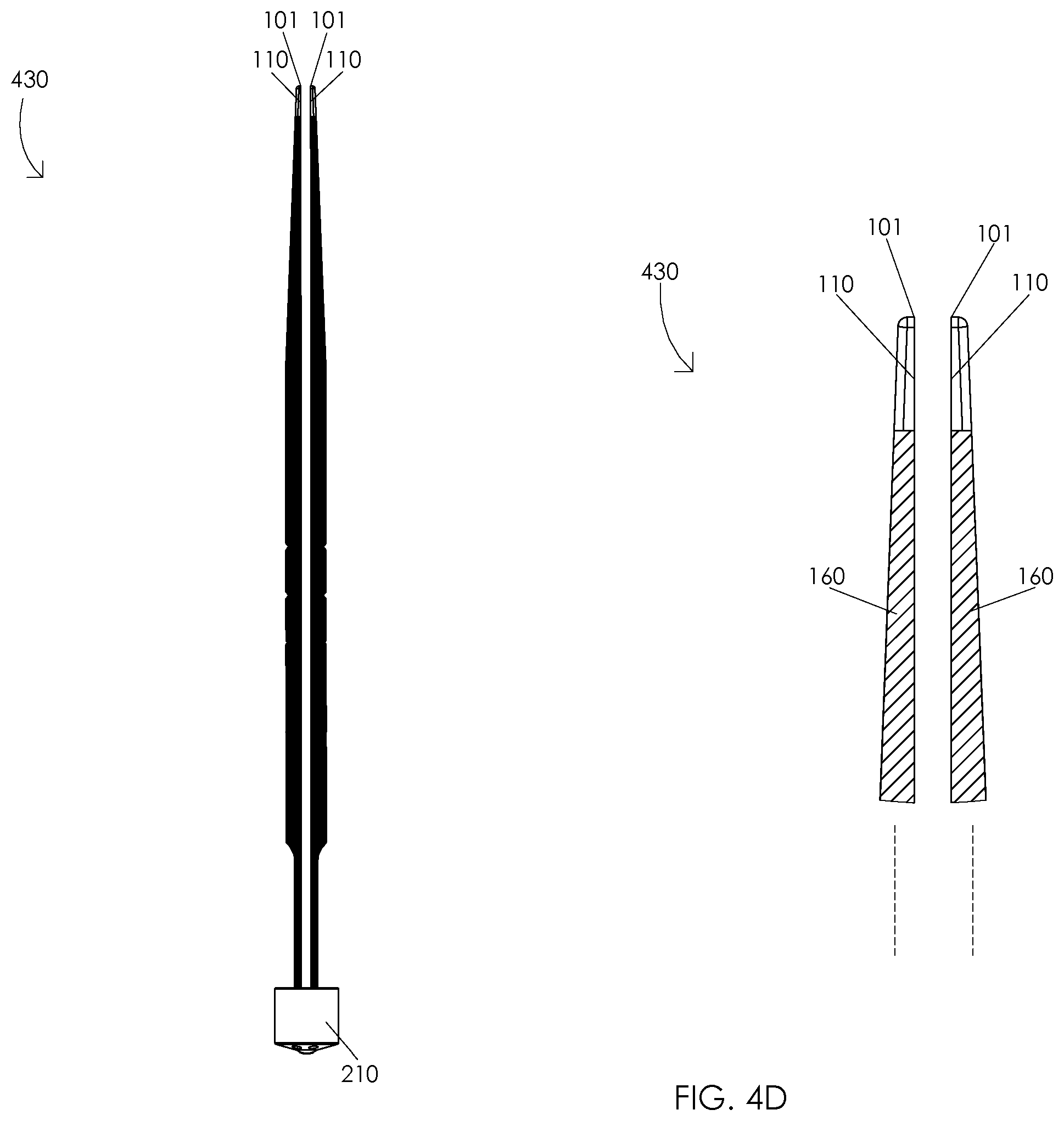
[0051] FIGS. 4A, 4B, 4C, 4D, and 4E are schematic diagrams illustrating a gradual opening of a bipolar forceps. FIG. 4A illustrates forceps jaws in a closed orientation 400. Illustratively, forceps jaws 160 may comprise forceps jaws in a closed orientation 400, e.g., when a first forceps arm conductor tip 110 contacts a second forceps arm conductor tip 110. In one or more embodiments, forceps jaws 160 may comprise forceps jaws in a closed orientation 400, e.g., when a distal end of a first forceps arm conductor tip 110 contacts a distal end of a second forceps arm conductor tip 110 and a proximal end of the first forceps arm conductor tip 110 contacts a proximal end of the second forceps arm conductor tip 110. Illustratively, forceps jaws 160 may comprise forceps jaws in a closed orientation 400, e.g., when a first forceps jaw 160 contacts a second forceps jaw 160. In one or more embodiments, forceps jaws 160 may comprise forceps jaws in a closed orientation 400, e.g., when a distal end of a first forceps jaw 160 contacts a distal end of a second forceps jaw 160 and a proximal end of the first forceps jaw 160 contacts a proximal end of the second forceps jaw 160. Illustratively, forceps jaws 160 may comprise forceps jaws in a closed orientation 400 when a force having a magnitude greater than 1.5 pounds is applied to a lateral portion of forceps arms 100, e.g., forceps jaws 160 may comprise forceps jaws in a closed orientation 400 when a force having a magnitude of 2.5 pounds is applied to a lateral portion of forceps arms 100. In one or more embodiments, forceps jaws 160 may comprise forceps jaws in a closed orientation 400 when a force less than or equal to 1.5 pounds is applied to a lateral portion of forceps arms 100.
[0052] FIG. 4B illustrates forceps jaws in a first partially closed orientation 410. Illustratively, a reduction of a force applied to a lateral portion of forceps arms 100 may be configured to gradually open forceps jaws 160 from forceps jaws in a closed orientation 400 to forceps jaws in a first partially closed orientation 410. In one or more embodiments, a reduction of a force applied to a lateral portion of forceps arms 100 may be configured to separate proximal ends of forceps jaws 160. Illustratively, a reduction of a force applied to a lateral portion of forceps arms 100 may be configured to increase a distance between a proximal end of first forceps jaw 160 and a proximal end of second forceps jaw 160. In one or more embodiments, a proximal end of a first forceps jaw 160 may be separated from a proximal end of a second forceps jaw 160 by a first partially closed separation distance 460, e.g., when forceps jaws 160 comprise forceps jaws in a first partially closed orientation 410. Illustratively, a proximal end of a first forceps jaw 160 may be separated from a proximal end of a second forceps jaw 160 by a first partially closed separation distance 460 in a range of 0.01 to 0.049 inches when forceps jaws 160 comprise forceps jaws in a first partially closed orientation 410, e.g., a proximal end of a first forceps jaw 160 may be separated from a proximal end of a second forceps jaw 160 by a first partially closed separation distance 460 of 0.03 inches when forceps jaws 160 comprise forceps jaws in a first partially closed orientation 410. In one or more embodiments, a proximal end of a first forceps jaw 160 may be separated from a proximal end of a second forceps jaw 160 by a first partially closed separation distance 460 less than 0.01 inches or greater than 0.049 inches when forceps jaws 160 comprise forceps jaws in a first partially closed orientation 410. Illustratively, a reduction of a force applied to a lateral portion of forceps arms 100 may be configured to separate proximal ends of forceps arm conductor tips 110. In one or more embodiments, a reduction of a force applied to a lateral portion of forceps arms 100 may be configured to increase a separation distance between a proximal end of first forceps arm conductor tip 110 and a proximal end of second forceps arm conductor tip 110. Illustratively, a reduction of a force applied to a lateral portion of forceps arms 100 may be configured to reduce a contact area between first forceps arm conductor tip 110 and second forceps arm conductor tip 110. In one or more embodiments, a reduction of a force applied to a lateral portion of forceps arms 100 may be configured to spread a tissue, dissect a tissue, etc. Illustratively, a surgeon may insert forceps arm distal ends 101 into a tissue, e.g., when forceps jaws 160 comprise forceps jaws in a closed orientation 400. In one or more embodiments, the surgeon may reduce a force applied to a lateral portion of forceps arms 100 and gradually open forceps jaws 160 from forceps jaws in a closed orientation 400 to forceps jaws in a first partially closed orientation 410. Illustratively, gradually opening forceps jaws 160 from forceps jaws in a closed orientation 400 to forceps jaws in a first partially closed orientation 410 may be configured to spread the tissue, dissect the tissue, etc.
[0053] FIG. 4C illustrates forceps jaws in a second partially closed orientation 420. Illustratively, a reduction of a force applied to a lateral portion of forceps arms 100 may be configured to gradually open forceps jaws 160 from forceps jaws in a first partially closed orientation 410 to forceps jaws in a second partially closed orientation 420. In one or more embodiments, a reduction of a force applied to a lateral portion of forceps arms 100 may be configured to separate proximal ends of forceps jaws 160. Illustratively, a reduction of a force applied to a lateral portion of forceps arms 100 may be configured to increase a distance between a proximal end of first forceps jaw 160 and a proximal end of second forceps jaw 160. In one or more embodiments, a proximal end of a first forceps jaw 160 may be separated from a proximal end of a second forceps jaw 160 by a second partially closed separation distance 450, e.g., when forceps jaws 160 comprise forceps jaws in a second partially closed orientation 420. Illustratively, a proximal end of a first forceps jaw 160 may be separated from a proximal end of a second forceps jaw 160 by a second partially closed separation distance 450 in a range of 0.05 to 0.15 inches when forceps jaws 160 comprise forceps jaws in a second partially closed orientation 420, e.g., a proximal end of a first forceps jaw 160 may be separated from a proximal end of a second forceps jaw 160 by a second partially closed separation distance 450 of 0.1 inches when forceps jaws 160 comprise forceps jaws in a second partially closed orientation 420. In one or more embodiments, a proximal end of a first forceps jaw 160 may be separated from a proximal end of a second forceps jaw 160 by a second partially closed separation distance 450 less than 0.05 inches or greater than 0.15 inches when forceps jaws 160 comprise forceps jaws in a second partially closed orientation 420. Illustratively, a reduction of a force applied to a lateral portion of forceps arms 100 may be configured to separate proximal ends of forceps arm conductor tips 110. In one or more embodiments, a reduction of a force applied to a lateral portion of forceps arms 100 may be configured to increase a separation distance between a proximal end of first forceps arm conductor tip 110 and a proximal end of second forceps arm conductor tip 110. Illustratively, a reduction of a force applied to a lateral portion of forceps arms 100 may be configured to reduce a contact area between first forceps arm conductor tip 110 and second forceps arm conductor tip 110. In one or more embodiments, a reduction of a force applied to a lateral portion of forceps arms 100 may be configured to spread a tissue, dissect a tissue, etc. Illustratively, a surgeon may insert forceps arm distal ends 101 into a tissue, e.g., when forceps jaws 160 comprise forceps jaws in a first partially closed orientation 410. In one or more embodiments, the surgeon may reduce a force applied to a lateral portion of forceps arms 100 and gradually open forceps jaws 160 from forceps jaws in a first partially closed orientation 410 to forceps jaws in a second partially closed orientation 420. Illustratively, gradually opening forceps jaws 160 from forceps jaws in a first partially closed orientation 410 to forceps jaws in a second partially closed orientation 420 may be configured to spread the tissue, dissect the tissue, etc.
[0054] FIG. 4D illustrates forceps jaws in a partially open orientation 430. Illustratively, a reduction of a force applied to a lateral portion of forceps arms 100 may be configured to gradually open forceps jaws 160 from forceps jaws in a second partially closed orientation 420 to forceps jaws in a partially open orientation 430. In one or more embodiments, a distal end of first forceps jaw 160 may be separated from a distal end of second forceps jaw 160, e.g., when forceps jaws 160 comprise forceps jaws in a partially open orientation 430. Illustratively, a distal end of first forceps arm conductor tip 110 may be separated from a distal end of second forceps arm conductor tip 110, e.g., when forceps jaws 160 comprise forceps jaws in a partially open orientation 430. In one or more embodiments, a reduction of a force applied to a lateral portion of forceps arms 100 may be configured to electrically disconnect first forceps arm conductor tip 110 and second forceps arm conductor tip 110. Illustratively, first forceps arm conductor tip 110 may be electrically disconnected from second forceps arm conductor tip 110, e.g., when forceps jaws 160 comprise forceps jaws in a partially open orientation 430. In one or more embodiments, a reduction of a force applied to a lateral portion of forceps arms 100 may be configured to spread a tissue, dissect a tissue, etc. Illustratively, a surgeon may insert forceps arm distal ends 101 into a tissue, e.g., when forceps jaws 160 comprise forceps jaws in a second partially closed orientation 420. In one or more embodiments, the surgeon may reduce a force applied to a lateral portion of forceps arms 100 and gradually open forceps jaws 160 from forceps jaws in a second partially closed orientation 420 to forceps jaws in a partially open orientation 430. Illustratively, gradually opening forceps jaws 160 from forceps jaws in a second partially closed orientation 420 to forceps jaws in a partially open orientation 430 may be configured to spread the tissue, dissect the tissue, etc.
[0055] FIG. 4E illustrates forceps jaws in a fully open orientation 440. Illustratively, a reduction of a force applied to a lateral portion of forceps arms 100 may be configured to gradually open forceps jaws 160 from forceps jaws in a partially open orientation 430 to forceps jaws in a fully open orientation 440. In one or more embodiments, forceps arm distal ends 101 may be separated by a distance in a range of 0.5 to 0.7 inches when forceps jaws 160 comprise forceps jaws in a fully open orientation 440, e.g., forceps arm distal ends 101 may be separated by a distance of 0.625 inches when forceps jaws 160 comprise forceps jaws in a fully open orientation 440. Illustratively, forceps arm distal ends 101 may be separated by a distance less than 0.5 inches or greater than 0.7 inches when forceps jaws 160 comprise forceps jaws in a fully open orientation 440. In one or more embodiments, forceps jaws 160 may comprise forceps jaws in a fully open orientation 440, e.g., when no force is applied to a lateral portion of forceps arms 100.
[0056] FIGS. 5A, 5B, and 5C are schematic diagrams illustrating a uniform compression of a vessel 560. In one or more embodiments, vessel 560 may comprise a blood vessel of an arteriovenous malformation. FIG. 5A illustrates an uncompressed vessel 500. Illustratively, vessel 560 may comprise an uncompressed vessel 500, e.g., when vessel 560 has a natural geometry. In one or more embodiments, vessel 560 may comprise an uncompressed vessel, e.g., when forceps jaws 160 comprise forceps jaws in a partially closed orientation 310. Illustratively, a surgeon may dispose vessel 560 between first forceps arm conductor tip 110 and second forceps arm conductor tip 110, e.g., when forceps jaws 160 comprise forceps jaws in an open orientation 300. In one or more embodiments, an application of a force to a lateral portion of forceps arms 100 may be configured to gradually close forceps jaws 160 from forceps jaws in an open orientation 300 to forceps jaws in a partially closed orientation 310. Illustratively, vessel 560 may electrically connect first forceps arm conductor tip 110 and second forceps arm conductor tip 110, e.g., when vessel 560 comprises an uncompressed vessel 500. In one or more embodiments, a surgeon may identify an orientation of forceps jaws 160 wherein conductor tips 110 initially contact vessel 560. Illustratively, a geometry of forceps arms 100 may be configured to allow a surgeon to visually identify an orientation of forceps jaws 160 wherein conductor tips 110 initially contact vessel 560. In one or more embodiments, a mass of forceps arms 100 may be configured to allow a surgeon to tactilely identify an orientation of forceps jaws 160 wherein conductor tips 110 initially contact vessel 560. Illustratively, a geometry of forceps arms 100 and a mass of forceps arms 100 may be configured to allow a surgeon to both visually and tactilely identify an orientation of forceps jaws 160 wherein conductor tips 110 initially contact vessel 560.
[0057] FIG. 5B illustrates a partially compressed vessel 510. Illustratively, an application of a force to a lateral portion of forceps arms 100 may be configured to uniformly compress vessel 560 from an uncompressed vessel 500 to a partially compressed vessel 510. In one or more embodiments, an application of a force to a lateral portion of forceps arms 100 may be configured to uniformly increase a contact area between vessel 560 and forceps arm conductor tips 110. Illustratively, vessel 560 may electrically connect first forceps arm conductor tip 110 and second forceps arm conductor tip 110, e.g., when vessel 560 comprises a partially compressed vessel 510. In one or more embodiments, an application of a force to a lateral portion of forceps arms 100 may be configured to compress vessel 560 wherein vessel 560 maintains a symmetrical geometry with respect to a medial axis of vessel 560. Illustratively, vessel 560 may have a symmetrical geometry with respect to a medial axis of vessel 560 when vessel 560 comprises a partially compressed vessel 510. In one or more embodiments, forceps jaws 160 may be configured to compress vessel 560 wherein no portion of vessel 560 is compressed substantially more than another portion of vessel 560, e.g., forceps jaws 160 may be configured to evenly compress vessel 560 without pinching a first portion of vessel 560 or bulging a second portion of vessel 560. Illustratively, vessel 560 may be evenly compressed when vessel 560 comprises a partially compressed vessel 510.
[0058] FIG. 5C illustrates a fully compressed vessel 520. Illustratively, an application of a force to a lateral portion of forceps arms 100 may be configured to uniformly compress vessel 560 from a partially compressed vessel 510 to a fully compressed vessel 520. In one or more embodiments, an application of a force to a lateral portion of forceps arms 100 may be configured to uniformly increase a contact area between vessel 560 and forceps arm conductor tips 110. Illustratively, vessel 560 may electrically connect first forceps arm conductor tip 110 and second forceps arm conductor tip 110, e.g., when vessel 560 comprises a fully compressed vessel 520. In one or more embodiments, a surgeon may uniformly cauterize vessel 560, e.g., when vessel 560 comprises a fully compressed vessel 520. Illustratively, a surgeon may uniformly achieve hemostasis of vessel 560, e.g., when vessel 560 comprises a fully compressed vessel 520. In one or more embodiments, an application of a force to a lateral portion of forceps arms 100 may be configured to compress vessel 560 wherein vessel 560 maintains a symmetrical geometry with respect to a medial axis of vessel 560. Illustratively, vessel 560 may have a symmetrical geometry with respect to a medial axis of vessel 560 when vessel 560 comprises a fully compressed vessel 520. In one or more embodiments, forceps jaws 160 may be configured to compress vessel 560 wherein no portion of vessel 560 is compressed substantially more than another portion of vessel 560, e.g., forceps jaws 160 may be configured to evenly compress vessel 560 without pinching a first portion of vessel 560 or bulging a second portion of vessel 560. Illustratively, vessel 560 may be evenly compressed when vessel 560 comprises a fully compressed vessel 520.
[0059] In an embodiment of the bipolar forceps assembly 200, the forceps arm 100 is configured to efficiently transfer thermal energy or heat away from the conductor tips 110 at a rate sufficient to maintain the thermal energy of the conductor tips 100 below a designated threshold during operation of the bipolar forceps assembly 200. Below the designated threshold, the conductor tips 110 are less likely to damage targeted and non-targeted biological tissue, such as by sticking or charring, during operation. The designated threshold can vary according to a number of factors, such as, temperature, the type of biological tissue, the thermal conductivity or K-value (W/m K) of the material of the arms and conductor tips, operation time, and the like. For example, cellular response to temperature can generally be categorized as follows: 98.6.degree. F. (37.degree. C.) normal body temperature; about 122.degree.-140.degree. F. (50-60.degree. C.) results in cell death over several minutes; about 194.degree. F. (90.degree. C.) causes instant cell death, protein denaturation, desiccation, and results in optimal "white" coagulation; about 212.degree. F. (100.degree. C.) vaporization, destructive expansion, vapor bubbles with arcing; and about 392.degree. F. (200.degree. C.) carbonization and charring. For another example, the thermal conductivity of copper is about 205% greater than aluminum, and 2300% greater than stainless steel (Half Hard Copper.apprxeq.340 W/m K; Aluminum.apprxeq.164 W/m K; Stainless Steel.apprxeq.14.4 W/m K; Silver.apprxeq.403 W/m K).
[0060] For efficient transfer of thermal energy, the forceps arm 100 can comprise a material having a thermal conductivity value greater than about 200 W/m K. For example, the material can comprise copper or copper alloy, including, but not limited to, pure copper, half hard, full hard, brass, copper-nickel, beryllium-copper, bronze, cupronickel, and the like. Although less cost-effective, the material properties of copper and/or copper alloy provide a higher thermal conductivity than other material typically used for bipolar forceps, such as, aluminum, stainless steel, and the like.
[0061] In an embodiment of the bipolar forceps assembly 200, an outer surface 600 of the conductor tips 110 may be at least partially covered with a plating layer 602 having desirable material characteristics, such as, non-stick properties (FIG. 5A). For example, the plating layer 302 may be a plating material, such as silver or silver alloy due to their applicable material characteristics and cost. Generally, silver has applicable material characteristics for plating the conductor tips 110, including, high electrical conductivity, high thermal conductivity, biocompatibility, antimicrobial and antibacterial, and corrosion resistance. In addition, silver or silver alloy is cost-effective in comparison to other plating materials, such as, gold, platinum, and the like. The plating material can be any suitable silver alloy, including, but not limited to, pure silver, silver titanium, sterling silver, silver nickel, silver iron, and the like. However, alternate embodiments may use other suitable materials, such as, gold, platinum, and the like.
[0062] The plating layer 602 can be deposited onto the conductor tips 110 using any suitable process, including, but not limited to electroplating, electroless plating, electrolytic plating, and the like. In the illustrated embodiment, the plating layer 602 is deposited directly onto the outer surface 600 of the conductor tips 110. For example, the plating layer 602 of silver alloy is deposited directly onto at least a portion of the outer surfaces of the copper alloy conductor tips 110. In this way, using suitable materials, such as copper and silver, eliminates the need for additional intermediate plating layers, thereby reducing manufacturing cost.
[0063] In alternate embodiments, the application of the plating layer 602 may include additional steps. For example, the application of the plating layer 602 may include depositing multiple layers of the plating material. Alternatively, the application of the plating layer 602 may include depositing additional layers of other materials, such as, nickel, gold, platinum, palladium, rhodium, and the like. The application of the plating layer 602 may include surface preparation processes, such as, cleaning, removing ionic and non-ionic residues, applying organic solvent, applying water-soluble flux,
[0064] During operation, thermal energy transfers from the conductor tips 110 through the forceps arms 100 and to the surrounding atmosphere. The combination of forceps arms 100 comprised of copper alloy and silver alloy plated conductor tips 110 provide a cost-effective bipolar forceps assembly 200 that can efficiently transfer thermal energy or heat away from the conductor tips 100 at a rate sufficient to maintain the thermal energy of the conductor tips 110 below the designated threshold during operation.
[0065] FIG. 6 is a side view of an alternate embodiment of a forceps arm. FIG. 7A is a partial side view of the alternate embodiment of the forceps arm. FIG. 7B is a partial exploded view of the alternate embodiment of the forceps arm. FIG. 8 is a top view of the alternate embodiment of the forceps arm. FIG. 9 is an enlarged top view of the alternate embodiment of the forceps arm. In an exemplary embodiment, the forceps arm 700 is similar to the embodiment of FIG. 1, except that each of the forceps arm 700 includes a first thermal portion 702 comprising a first thermal material and a second thermal portion 704 comprising a second thermal material. The first thermal portion 702 is attached to the second thermal portion 704 at a thermal interface 706. For example, the first thermal portion 702 includes a first thermal proximal end 710 and a first thermal distal end 712. The second thermal portion 704 includes a second thermal proximal end 714 and a second thermal distal end 716. The first thermal distal end 712 is configured for operative engagement with the second thermal proximal end 714 at the thermal interface 706. In the exemplary embodiment, the first thermal distal end 712 includes a female portion 716 configured to mate with a corresponding male portion 718 of the second thermal proximal end 714. However, in alternate embodiments, the first thermal distal end 712 may include a male portion configured to mate with a corresponding female portion of the second thermal proximal end 714.
[0066] In an exemplary embodiment, the first thermal portion 702 can be secured to the second thermal portion 704 with pins 720 inserted through corresponding through holes 722. For example, a pair of the pins 720 and through holes 722 may extend through transversely the male portion 718 and female portion 712. The pins 720 may be secured in any suitable manner, such as press-fit, adhesive, welding, soldering, and the like. In alternate embodiments, the first thermal portion 702 and the second thermal portion 704 may be attached to each other in any suitable manner, including, fasteners, adhesive, welding, soldering, and the like.
[0067] The forceps arm 700 is configured to efficiently transfer thermal energy or heat away from the conductor tips 110 at a rate sufficient to maintain the thermal energy of the conductor tips 100 below a designated threshold during operation of the bipolar forceps assembly. Below the designated threshold, the conductor tips 110 are less likely to damage targeted and non-targeted biological tissue, such as by sticking or charring, during operation. The designated threshold can vary according to a number of factors, such as, temperature, the type of biological tissue, the thermal conductivity or K-value (W/m K) of the material of the arms and conductor tips, operation time, and the like. For example, cellular response to temperature can generally be categorized as follows: 98.6.degree. F. (37.degree. C.) normal body temperature; about 122.degree.-140.degree. F. (50-60.degree. C.) results in cell death over several minutes; about 194.degree. F. (90.degree. C.) causes instant cell death, protein denaturation, desiccation, and results in optimal "white" coagulation; about 212.degree. F. (100.degree. C.) vaporization, destructive expansion, vapor bubbles with arcing; and about 392.degree. F. (200.degree. C.) carbonization and charring. For another example, the thermal conductivity of copper is about 205% greater than aluminum, and 2300% greater than stainless steel (Half Hard Copper.apprxeq.340 W/m K; Aluminum.apprxeq.164 W/m K; Stainless Steel.apprxeq.14.4 W/m K; Silver.apprxeq.403 W/m K).
[0068] The first thermal material may comprise a material having an electrical conductivity in a range of 30.0.times.106 to 40.0.times.106 Siemens per meter at a temperature of 20.0.degree. C., e.g., forceps arm 100 may be manufactured from a material having an electrical conductivity of 35.5.times.106 Siemens per meter at a temperature of 20.0.degree. C. Illustratively, forceps arm 700 may be manufactured from a material having an electrical conductivity of less than 30.0.times.106 Siemens per meter or greater than 40.0.times.106 Siemens per meter at a temperature of 20.0.degree. C. In one or more embodiments, forceps arm 100 may be manufactured from a material having a thermal conductivity in a range of 180.0 to 250.0 Watts per meter Kelvin at a temperature of 20.0.degree. C., e.g., forceps arm 100 may be manufactured from a material having a thermal conductivity of 204.0 Watts per meter Kelvin at a temperature of 20.0.degree. C. Illustratively, forceps arm 100 may be manufactured from a material having a thermal conductivity of less than 180.0 Watts per meter Kelvin or greater than 250.0 Watts per meter Kelvin at a temperature of 20.0.degree. C. In one or more embodiments, forceps arm 100 may be manufactured from a material having an electrical conductivity in a range of 30.0.times.106 to 40.0.times.106 Siemens per meter and a thermal conductivity in a range of 180.0 to 250.0 Watts per meter Kelvin at a temperature of 20.0.degree. C., e.g., forceps arm 100 may be manufactured from a material having an electrical conductivity of 35.5.times.106 Siemens per meter and a thermal conductivity of 204.0 Watts per meter Kelvin at a temperature of 20.0.degree. C. For example, the first thermal material may comprise an electrically conductive material, such as, aluminum, aluminum alloy, silver, silver alloy, stainless steel, graphite, gold alloy, conductive polymers, and the like.
[0069] The second thermal material can comprise a material having a thermal conductivity value greater than about 200 W/m K. For example, the material can comprise copper or copper alloy, including, but not limited to, pure copper, half hard, full hard, brass, copper-nickel, beryllium-copper, bronze, cupronickel, and the like. Although less cost-effective, the material properties of copper and/or copper alloy provide a higher thermal conductivity than other material typically used for bipolar forceps, such as, aluminum, stainless steel, and the like.
[0070] In an alternate embodiment, the forceps 700 of FIGS. 6-9 may include the forceps arm aperture 105 that is configured to reduce a mass of forceps arm 700.
[0071] It is to be understood that the above description is intended to be illustrative, and not restrictive. For example, the above-described embodiments (and/or aspects thereof) may be used in combination with each other. In addition, many modifications may be made to adapt a particular situation or material to the teachings of the subject matter set forth herein without departing from its scope. While the dimensions and types of materials described herein are intended to define the parameters of the disclosed subject matter, they are by no means limiting and are exemplary embodiments. Many other embodiments will be apparent to those of skill in the art upon reviewing the above description. The scope of the subject matter described herein should, therefore, be determined with reference to the appended claims, along with the full scope of equivalents to which such claims are entitled. In the appended claims, the terms "including" and "in which" are used as the plain English equivalents of the respective terms "comprising" and "wherein." Moreover, in the following claims, the terms "first," "second," and "third," etc. are used merely as labels, and are not intended to impose numerical requirements on their objects. Further, the limitations of the following claims are not written in means-plus-function format and are not intended to be interpreted based on 35 U.S.C. .sctn. 112(f), unless and until such claim limitations expressly use the phrase "means for" followed by a statement of function void of further structure.
[0072] As used herein, an element or step recited in the singular and proceeded with the word "a" or "an" should be understood as not excluding plural of said elements or steps, unless such exclusion is explicitly stated. Furthermore, references to "one embodiment" of the presently described subject matter are not intended to be interpreted as excluding the existence of additional embodiments that also incorporate the recited features. Moreover, unless explicitly stated to the contrary, embodiments "comprising" or "having" an element or a plurality of elements having a particular property may include additional such elements not having that property.
[0073] This written description uses examples to disclose several embodiments of the subject matter set forth herein, including the best mode, and also to enable a person of ordinary skill in the art to practice the embodiments of disclosed subject matter, including making and using the devices or systems and performing the methods. The patentable scope of the subject matter described herein is defined by the claims, and may include other examples that occur to those of ordinary skill in the art. Such other examples are intended to be within the scope of the claims if they have structural elements that do not differ from the literal language of the claims, or if they include equivalent structural elements with insubstantial differences from the literal languages of the claims.
[0074] The foregoing description of certain embodiments of the present inventive subject matter will be better understood when read in conjunction with the appended drawings. To the extent that the figures illustrate diagrams of the functional blocks of various embodiments, the functional blocks are not necessarily indicative of the division between hardware circuitry. Thus, for example, one or more of the functional blocks (for example, communication unit, control system, etc.) may be implemented in a single piece of hardware (for example, a general-purpose signal processor, microcontroller, random access memory, hard disk, and the like). Similarly, the programs may be stand-alone programs, may be incorporated as subroutines in an operating system, may be functions in an installed software package, and the like. The various embodiments are not limited to the arrangements and instrumentality shown in the drawings.
[0075] Since certain changes may be made in the above-described systems and methods, without departing from the spirit and scope of the inventive subject matter herein involved, it is intended that all of the subject matter of the above description or shown in the accompanying drawings shall be interpreted merely as examples illustrating the inventive concept herein and shall not be construed as limiting the inventive subject matter.
[0076] Changes can be made in the above constructions without departing from the scope of the disclosure, it is intended that all matter contained in the above description or shown in the accompanying drawings shall be interpreted as illustrative and not in a limiting sense.
* * * * *
D00000
D00001
D00002
D00003
D00004
D00005
D00006
D00007
D00008
D00009
D00010
D00011
D00012
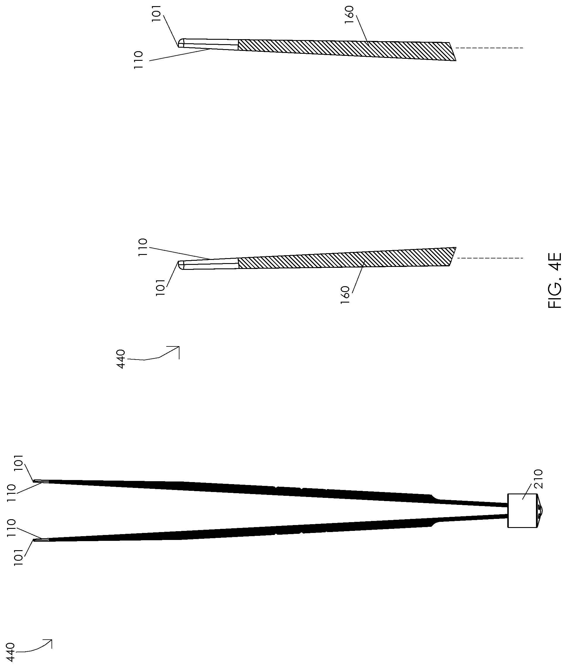
D00013

D00014

D00015

D00016

D00017

D00018

XML
uspto.report is an independent third-party trademark research tool that is not affiliated, endorsed, or sponsored by the United States Patent and Trademark Office (USPTO) or any other governmental organization. The information provided by uspto.report is based on publicly available data at the time of writing and is intended for informational purposes only.
While we strive to provide accurate and up-to-date information, we do not guarantee the accuracy, completeness, reliability, or suitability of the information displayed on this site. The use of this site is at your own risk. Any reliance you place on such information is therefore strictly at your own risk.
All official trademark data, including owner information, should be verified by visiting the official USPTO website at www.uspto.gov. This site is not intended to replace professional legal advice and should not be used as a substitute for consulting with a legal professional who is knowledgeable about trademark law.