Patient Support Bridge Methods And Apparatus
McNulty; Christopher Thomas ; et al.
U.S. patent application number 16/516760 was filed with the patent office on 2020-01-23 for patient support bridge methods and apparatus. The applicant listed for this patent is Hyperfine Research, Inc.. Invention is credited to Christopher Thomas McNulty, Todd Rearick.
| Application Number | 20200022612 16/516760 |
| Document ID | / |
| Family ID | 67515186 |
| Filed Date | 2020-01-23 |


View All Diagrams
| United States Patent Application | 20200022612 |
| Kind Code | A1 |
| McNulty; Christopher Thomas ; et al. | January 23, 2020 |
PATIENT SUPPORT BRIDGE METHODS AND APPARATUS
Abstract
According to some aspects, a bridge adapted for attachment to a magnetic resonance imaging system and configured to facilitate positioning a patient within the magnetic resonance imaging system is provided. Embodiments of the bridge comprise a support having a surface configured to support at least a portion of the patient, the support being moveable between an up position and a down position, wherein the surface is substantially vertical in the up position and substantially horizontal in the down position, a hinge configured to allow the support to be moved from the up position to the down position and vice versa, and a base configured to attach the bridge to the magnetic resonance imaging system. According to some aspects, a magnetic resonance imaging system is provided having a bridge configured to facilitate positioning a patient within the magnetic resonance imaging system attached thereto.
| Inventors: | McNulty; Christopher Thomas; (Guilford, CT) ; Rearick; Todd; (Cheshire, CT) | ||||||||||
| Applicant: |
|
||||||||||
|---|---|---|---|---|---|---|---|---|---|---|---|
| Family ID: | 67515186 | ||||||||||
| Appl. No.: | 16/516760 | ||||||||||
| Filed: | July 19, 2019 |
Related U.S. Patent Documents
| Application Number | Filing Date | Patent Number | ||
|---|---|---|---|---|
| 62811361 | Feb 27, 2019 | |||
| 62700711 | Jul 19, 2018 | |||
| Current U.S. Class: | 1/1 |
| Current CPC Class: | A61B 5/0555 20130101; A61B 90/14 20160201; G01R 33/34084 20130101; G01R 33/3802 20130101; G01R 33/307 20130101; G01R 33/422 20130101; A61B 5/70 20130101; G01R 33/34007 20130101; A61B 6/04 20130101; G01R 33/4833 20130101; G01R 33/543 20130101; G01R 33/445 20130101; G01R 33/3806 20130101 |
| International Class: | A61B 5/055 20060101 A61B005/055 |
Claims
1. A bridge adapted for attachment to a magnetic resonance imaging system and configured to facilitate positioning a patient within the magnetic resonance imaging system, the bridge comprising: a support having a surface configured to support at least a portion of the patient, the support being moveable between an up position and a down position, wherein the surface is substantially vertical in the up position and substantially horizontal in the down position; a hinge configured to allow the support to be moved from the up position to the down position and vice versa; and a base configured to attach the bridge to the magnetic resonance imaging system.
2. The bridge of claim 1, wherein the hinge comprises a pivot portion coupled to the support to allow the support to pivot between the up position and the down position.
3. The bridge of claim 2, wherein the support comprises a groove and the pivot portion comprises a tongue inserted into the groove to couple the pivot portion to the support.
4. The bridge of claim 3, wherein the tongue is comprised of a plastic material.
5. The bridge of claim 3, wherein the support is comprised of a plastic material.
6. The bridge of claim 2, wherein the pivot portion comprises a first bore and the base comprises a second bore, and wherein the hinge further comprises a shaft inserted through the first bore and the second bore to couple the pivot portion to the base and to allow the pivot portion to rotate about the shaft to cause the support to pivot between the up position and the down position.
7. The bridge of claim 1, wherein the surface of the support has a length of between 8 inches and 16 inches.
8. The bridge of claim 1, wherein the surface of the support has a width of between 12 inches and 30 inches.
9. The bridge of claim 1, wherein the bridge is rated for a 500 pound patient.
10. The bridge of claim 9, wherein the bridge has a safety factor of at least 2.5.
11. The bridge of claim 9, wherein the bridge has a safety factor greater than or equal to 2.5 and less than or equal to 4.0.
12. The bridge of claim 9, wherein the bridge has a safety factor greater than or equal to 2.5 and less than or equal to 4.3.
13. The bridge of claim 1, wherein the base includes a plurality of bores configured to allow the bridge to be bolted to the magnetic resonance imaging system.
14. The bridge of claim 13, wherein at least the portion of the base that includes the plurality of bores is made of steel.
15. The bridge of claim 13, wherein the bridge is bolted to a B.sub.0 magnet of the magnetic resonance imaging system.
16. The bridge of claim 2, wherein the bridge further comprises a counter-balance mechanism that resists pivoting of the support from the up position to the down position.
17. The bridge of claim 16, wherein the counter-balance mechanism comprises at least one torsion spring that resists pivoting of the support from the up position to the down position.
18. The bridge of claim 17, wherein the at least one torsion spring is coupled to the pivot portion so that, when the pivot portion is rotated, the at least one torsion spring slows the rate at which the support pivots from the up position to the down position.
19. The bridge of claim 18, further comprising a lock-out switch that, when activated, is configured to disable a motor drive of the magnetic resonance imaging system.
20. The bridge of claim 19, wherein the lock-out switch is configured to be activated when the support is moved to the down position and an additional weight is applied to the support.
21. The bridge of claim 19, wherein the lock-out switch is configured to be activated when the support is placed in the down position.
22. The bridge of claim 19, wherein the lock-switch comprises at least one sensor configured to detect when a patient is positioned on the support.
23. A magnetic resonance imaging system comprising: a B.sub.0 magnet configured to generate a magnetic field suitable for magnetic resonance imaging; a conveyance mechanism configured to allow the magnetic resonance imaging system to be moved to different locations; and a bridge configured to facilitate positioning a patient within the magnetic resonance imaging system, the bridge comprising: a support having a surface configured to support at least a portion of the patient, the support being moveable between an up position and a down position, wherein the surface is substantially vertical in the up position and substantially horizontal in the down position; a hinge configured to allow the support to be moved from the up position to the down position and vice versa; and a base attaching the bridge to the magnetic resonance imaging system.
24. The magnetic resonance imaging system of claim 23, wherein the hinge comprises a pivot portion coupled to the support to allow the support to pivot between the up position and the down position.
25. The magnetic resonance imaging system of claim 23, wherein the support comprises a groove and the pivot portion comprises a tongue inserted into the groove to couple the pivot portion to the support.
26. The magnetic resonance imaging system of claim 25, wherein the tongue is comprised of a plastic material to reduce eddy currents generated in the bridge when the magnetic resonance imaging system is operated.
27. The magnetic resonance imaging system of claim 25, wherein the support is comprised of a plastic material.
28. The magnetic resonance imaging system of claim 24, wherein the pivot portion comprises a first bore and the base comprises a second bore, the hinge further comprising a shaft inserted through the first bore and the second bore to couple the pivot portion to the base and to allow the pivot portion to rotate about the shaft to cause the support to pivot between the up position and the down position.
29. The magnetic resonance imaging system of claim 23, wherein the surface of the support has a length of between 8 inches and 16 inches.
30. The magnetic resonance imaging system of claim 23, wherein the surface of the support has a width of between 12 inches and 30 inches.
31. The magnetic resonance imaging system of claim 23, wherein the bridge is rated for a 500 pound patient.
32. The magnetic resonance imaging system of claim 31, wherein the bridge has a safety factor of at least 2.5.
33. The magnetic resonance imaging system of claim 31, wherein the bridge has a safety factor greater than or equal to 2.5 and less than or equal to 4.0.
34. The magnetic resonance imaging system of claim 31, wherein the bridge has a safety factor greater than or equal to 2.5 and less than or equal to 4.3.
35. The magnetic resonance imaging system of claim 1, wherein the base includes a plurality of bores accommodating respective bolts that attach the base to the magnetic resonance imaging system.
36. The magnetic resonance imaging system of claim 35, wherein at least the portion of the base comprising the plurality of bores is made of steel.
37. The magnetic resonance imaging system of claim 35, wherein the base of the bridge is bolted to the B.sub.0 magnet of the magnetic resonance imaging system.
38. The magnetic resonance imaging system of claim 24, wherein the bridge further comprises a counter-balance mechanism that resists pivoting of the support from the up position to the down position.
39. The magnetic resonance imaging system of claim 38, wherein the counter-balance mechanism comprises at least one torsion spring that resists pivoting of the support from the up position to the down position.
40. The magnetic resonance imaging system of claim 39, wherein the at least one torsion spring is coupled to the pivot portion so that, when the pivot portion is rotated, the at least one torsion spring slows the rate at which the support pivots from the up position to the down position.
41. The magnetic resonance imaging system of claim 23, wherein the bridge further comprises a lock-out switch coupled to the conveyance mechanism that, when activated, disables a motor drive of the conveyance mechanism.
42. The magnetic resonance imaging system of claim 41, wherein the lock-out switch is activated when the support is moved to the down position and an additional weight is applied to the support.
43. The magnetic resonance imaging system of claim 42, wherein the lock-out switch comprises at least one sensor configured to detect when a patient is positioned on the support.
44. A method of imaging a portion of anatomy of a patient while the patient is at least partially supported by a standard medical bed, the method comprising: positioning a magnetic resonance imaging system and the bed proximate one another; moving a bridge attached to the magnetic resonance imaging system from a vertical position to a horizontal position so that the bridge overlaps a portion of the bed; positioning the patient via the bridge so that the portion of anatomy of the patient is within an imaging region of the magnetic resonance imaging system; and acquiring at least one magnetic resonance image of the portion of the anatomy of the patient while the patient is at least partially supported by the bed and at least partially supported by the bridge.
45. The method of claim 44, wherein moving the bridge from the vertical position to a horizontal position disables a conveyance mechanism of the magnetic resonance imaging system.
46. The method of claim 44, wherein positioning the patient via the bridge disables a conveyance mechanism of the magnetic resonance imaging system.
Description
CROSS REFERENCE TO RELATED APPLICATIONS
[0001] This application claims priority under 35 U.S.C. .sctn. 119 to U.S. Provisional Application Ser. No. 62/700,711 filed Jul. 19, 2018 and titled "Methods and Apparatus for Patient Positioning in Magnetic Resonance Imaging," and U.S. Provisional Application Ser. No. 62/811,361 filed Feb. 27, 2019 and titled "Methods and Apparatus for Patient Positioning in Magnetic Resonance Imaging," each application of which is herein incorporated by reference in its entirety.
BACKGROUND
[0002] Magnetic resonance imaging (MRI) provides an important imaging modality for numerous applications and is widely utilized in clinical and research settings to produce images of the inside of the human body. As a generality, MRI is based on detecting magnetic resonance (MR) signals, which are electromagnetic waves emitted by atoms in response to state changes resulting from applied electromagnetic fields. For example, nuclear magnetic resonance (NMR) techniques involve detecting MR signals emitted from the nuclei of excited atoms upon the re-alignment or relaxation of the nuclear spin of atoms in an object being imaged (e.g., atoms in the tissue of the human body). Detected MR signals may be processed to produce images, which in the context of medical applications, allows for the investigation of internal structures and/or biological processes within the body for diagnostic, therapeutic and/or research purposes.
[0003] MRI provides an attractive imaging modality for biological imaging due to the ability to produce non-invasive images having relatively high resolution and contrast without the safety concerns of other modalities (e.g., without needing to expose the subject to ionizing radiation, e.g., x-rays, or introducing radioactive material to the body). Additionally, MRI is particularly well suited to provide soft tissue contrast, which can be exploited to image subject matter that other imaging modalities are incapable of satisfactorily imaging. Moreover, MR techniques are capable of capturing information about structures and/or biological processes that other modalities are incapable of acquiring. However, there are a number of drawbacks to MRI that, for a given imaging application, may involve the relatively high cost of the equipment, limited availability and/or difficulty in gaining access to clinical MRI scanners and/or the length of the image acquisition process.
[0004] The trend in clinical MRI has been to increase the field strength of MRI scanners to improve one or more of scan time, image resolution, and image contrast, which, in turn, continues to drive up costs. The vast majority of installed MRI scanners operate at 1.5 or 3 tesla (T), which refers to the field strength of the main magnetic field B.sub.0. A rough cost estimate for a clinical MRI scanner is approximately one million dollars per tesla, which does not factor in the substantial operation, service, and maintenance costs involved in operating such MRI scanners.
[0005] Additionally, conventional high-field MRI systems typically require large superconducting magnets and associated electronics to generate a strong uniform static magnetic field (B.sub.0) in which an object (e.g., a patient) is imaged. The size of such systems is considerable with a typical MRI installment including multiple rooms for the magnet, electronics, thermal management system, and control console areas. The size and expense of MRI systems generally limits their usage to facilities, such as hospitals and academic research centers, which have sufficient space and resources to purchase and maintain them. The high cost and substantial space requirements of high-field MRI systems results in limited availability of MRI scanners. As such, there are frequently clinical situations in which an MRI scan would be beneficial, but due to one or more of the limitations discussed above, is not practical or is impossible, as discussed in further detail below.
SUMMARY
[0006] Some embodiments include a bridge adapted for attachment to a magnetic resonance imaging system and configured to facilitate positioning a patient within the magnetic resonance imaging system, the bridge comprising a support having a surface configured to support at least a portion of the patient, the support being moveable between an up position and a down position, wherein the surface is substantially vertical in the up position and substantially horizontal in the down position, a hinge configured to allow the support to be moved from the up position to the down position and vice versa, and a base configured to attach the bridge to the magnetic resonance imaging system.
[0007] Some embodiments include a magnetic resonance imaging system comprising a B.sub.0 magnet configured to generate a magnetic field suitable for magnetic resonance imaging, a conveyance mechanism configured to allow the magnetic resonance imaging system to be moved to different locations, and a bridge configured to facilitate positioning a patient within the magnetic resonance imaging system, the bridge comprising a support having a surface configured to support at least a portion of the patient, the support being moveable between an up position and a down position, wherein the surface is substantially vertical in the up position and substantially horizontal in the down position, a hinge configured to allow the support to be moved from the up position to the down position and vice versa, and a base attaching the bridge to the magnetic resonance imaging system.
[0008] Some embodiments include a method of imaging a portion of anatomy of a patient while the patient is at least partially supported by a standard medical bed, the method comprising positioning a magnetic resonance imaging system and the bed proximate one another, moving a bridge attached to the magnetic resonance imaging system from a vertical position to a horizontal position so that the bridge overlaps a portion of the bed, positioning the patient via the bridge so that the portion of anatomy of the patient is within an imaging region of the magnetic resonance imaging system, and acquiring at least one magnetic resonance image of the portion of the anatomy of the patient while the patient is at least partially supported by the bed and at least partially supported by the bridge.
BRIEF DESCRIPTION OF THE DRAWINGS
[0009] Various aspects and embodiments of the disclosed technology will be described with reference to the following figures. It should be appreciated that the figures are not necessarily drawn to scale.
[0010] FIG. 1 illustrates a portable magnetic resonance imaging system with a bridge to assist in positioning a patient;
[0011] FIG. 2A illustrates a fold-up bridge shown in a vertical or up position, in accordance with some embodiment;
[0012] FIG. 2B illustrates the fold-up bridge illustrated in FIG. 2A in a horizontal or down position, in accordance with some embodiments.
[0013] FIG. 3 illustrates components of a fold-up bridge, in accordance with some embodiments;
[0014] FIG. 4A illustrates a model of a bridge, in accordance with some embodiments;
[0015] FIG. 4B illustrates a stress plot of the model of the bridge illustrated in FIG. 3A;
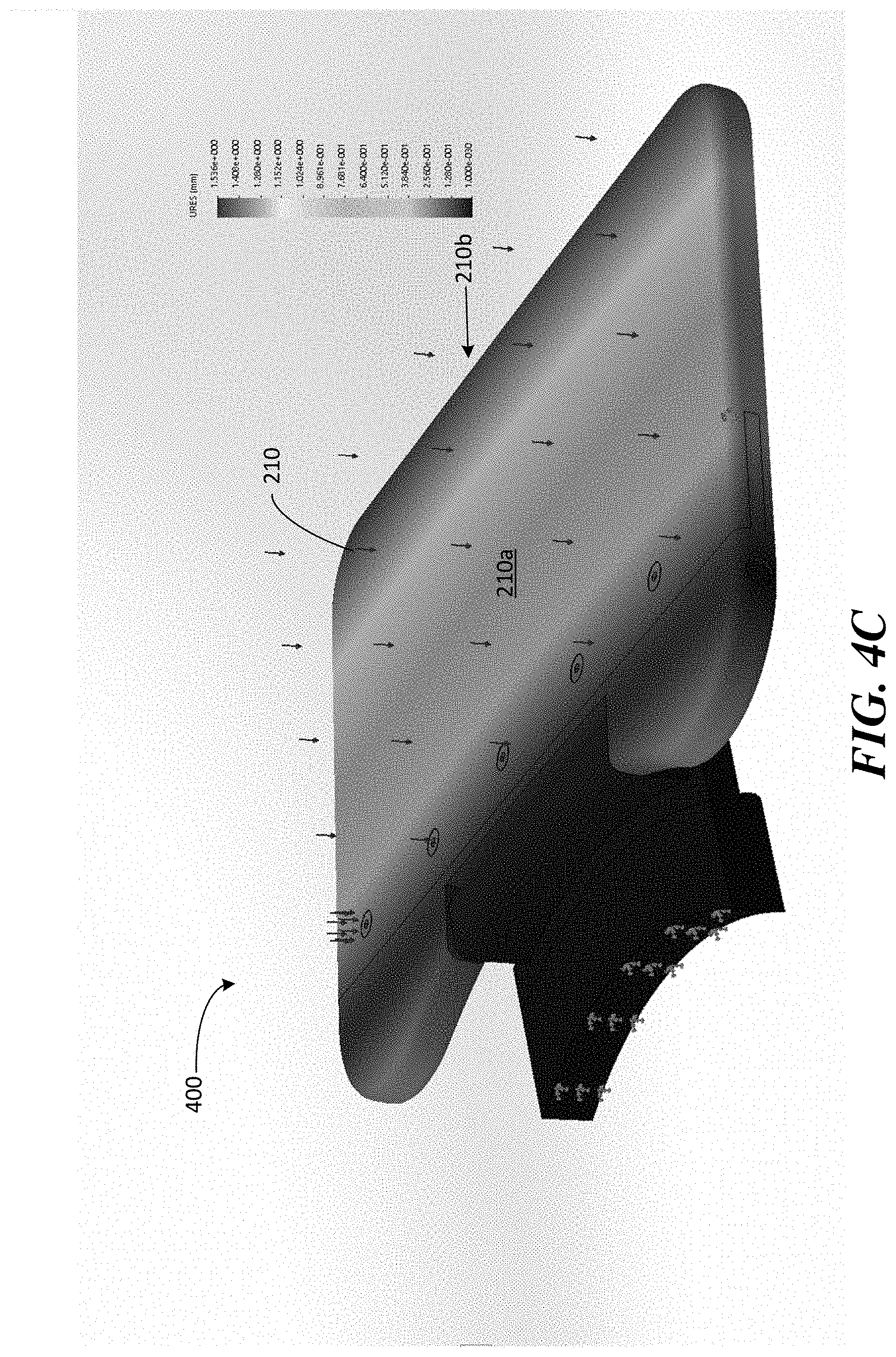
[0016] FIG. 4C illustrates a deflection plot of the model of the bridge illustrated in FIG. 3A.
[0017] FIG. 4D is Figure A.19 from the IEC 60601-1 illustrating the human body mass distribution for patient support surfaces;
[0018] FIGS. 5A and 5B illustrate components of a fold-up bridge with a counter-balance mechanism, in accordance with some embodiments;
[0019] FIG. 6A illustrates a portable MRI system with a bridge in the vertical position;
[0020] FIG. 6B illustrates a portable MRI system with a bridge in the horizontal position;
[0021] FIG. 6C illustrates a patient positioned within a portable MRI system and supported by a fold-out bridge.
DETAILED DESCRIPTION
[0022] The MRI scanner market is overwhelmingly dominated by high-field systems, and particularly for medical or clinical MRI applications. As discussed above, the general trend in medical imaging has been to produce MRI scanners with increasingly greater field strengths, with the vast majority of clinical MRI scanners operating at 1.5T or 3T, with higher field strengths of 7T and 9T used in research settings. As used herein, "high-field" refers generally to MRI systems presently in use in a clinical setting and, more particularly, to MRI systems operating with a main magnetic field (i.e., a B.sub.0 field) at or above 1.5T, though clinical systems operating between 0.5T and 1.5T are often also characterized as "high-field." Field strengths between approximately 0.2T and 0.5T have been characterized as "mid-field" and, as field strengths in the high-field regime have continued to increase, field strengths in the range between 0.5T and 1T have also been characterized as mid-field. By contrast, "low-field" refers generally to MRI systems operating with a B.sub.0 field of less than or equal to approximately 0.2T, though systems having a B.sub.0 field of between 0.2T and approximately 0.3T have sometimes been characterized as low-field as a consequence of increased field strengths at the high end of the high-field regime. Within the low-field regime, low-field MRI systems operating with a B.sub.0 field of less than 0.1T are referred to herein as "very low-field" and low-field MRI systems operating with a B.sub.0 field of less than 10 mT are referred to herein as "ultra-low field."
[0023] As discussed above, conventional MRI systems require specialized facilities. An electromagnetically shielded room is required for the MRI system to operate and the floor of the room must be structurally reinforced. Additional rooms must be provided for the high-power electronics and the scan technician's control area. Secure access to the site must also be provided. In addition, a dedicated three-phase electrical connection must be installed to provide the power for the electronics that, in turn, are cooled by a chilled water supply. Additional HVAC capacity typically must also be provided. These site requirements are not only costly, but significantly limit the locations where MRI systems can be deployed. Conventional clinical MRI scanners also require substantial expertise to both operate and maintain. These highly trained technicians and service engineers add large on-going operational costs to operating an MRI system. Conventional MRI, as a result, is frequently cost prohibitive and is severely limited in accessibility, preventing MRI from being a widely available diagnostic tool capable of delivering a wide range of clinical imaging solutions wherever and whenever needed. Typically, patient must visit one of a limited number of facilities at a time and place scheduled in advance, preventing MRI from being used in numerous medical applications for which it is uniquely efficacious in assisting with diagnosis, surgery, patient monitoring and the like.
[0024] As discussed above, high-field MRI systems require specially adapted facilities to accommodate the size, weight, power consumption and shielding requirements of these systems. For example, a 1.5T MRI system typically weighs between 4-10 tons and a 3T MRI system typically weighs between 8-20 tons. In addition, high-field MRI systems generally require significant amounts of heavy and expensive shielding. Many mid-field scanners are even heavier, weighing between 10-20 tons due, in part, to the use of very large permanent magnets and/or yokes. Commercially available low-field MRI systems (e.g., operating with a B.sub.0 magnetic field of 0.2T) are also typically in the range of 10 tons or more due to the large amounts of ferromagnetic material used to generate the B.sub.0 field, with additional tonnage in shielding. To accommodate this heavy equipment, rooms (which typically have a minimum size of 30-50 square meters) have to be built with reinforced flooring (e.g., concrete flooring), and must be specially shielded to prevent electromagnetic radiation from interfering with operation of the MRI system. Thus, available clinical MRI systems are immobile and require the significant expense of a large, dedicated space within a hospital or facility, and in addition to the considerable costs of preparing the space for operation, require further additional on-going costs in expertise in operating and maintaining the system.
[0025] In addition, currently available MRI systems typically consume large amounts of power. For example, common 1.5T and 3T MRI systems typically consume between 20-40 kW of power during operation, while available 0.5T and 0.2T MRI systems commonly consume between 5-20 kW, each using dedicated and specialized power sources. Unless otherwise specified, power consumption is referenced as average power consumed over an interval of interest. For example, the 20-40 kW referred to above indicates the average power consumed by conventional MRI systems during the course of image acquisition, which may include relatively short periods of peak power consumption that significantly exceeds the average power consumption (e.g., when the gradient coils and/or RF coils are pulsed over relatively short periods of the pulse sequence). Intervals of peak (or large) power consumption are typically addressed via power storage elements (e.g., capacitors) of the MRI system itself. Thus, the average power consumption is the more relevant number as it generally determines the type of power connection needed to operate the device. As discussed above, available clinical MRI systems must have dedicated power sources, typically requiring a dedicated three-phase connection to the grid to power the components of the MRI system. Additional electronics are then needed to convert the three-phase power into single-phase power utilized by the MRI system. The many physical requirements of deploying conventional clinical MRI systems creates a significant problem of availability and severely restricts the clinical applications for which MRI can be utilized.
[0026] Accordingly, the many requirements of high-field MRI render installations prohibitive in many situations, limiting their deployment to large institutional hospitals or specialized facilities and generally restricting their use to tightly scheduled appointments, requiring the patient to visit dedicated facilities at times scheduled in advance. Thus, the many restrictions on high field MRI prevent MRI from being fully utilized as an imaging modality. Despite the drawbacks of high-field MRI mentioned above, the appeal of the significant increase in SNR at higher fields continues to drive the industry to higher and higher field strengths for use in clinical and medical MRI applications, further increasing the cost and complexity of MRI scanners, and further limiting their availability and preventing their use as a general-purpose and/or generally-available imaging solution.
[0027] The low SNR of MR signals produced in the low-field regime (particularly in the very low-field regime) has prevented the development of a relatively low cost, low power and/or portable MRI system. Conventional "low-field" MRI systems operate at the high end of what is typically characterized as the low-field range (e.g., clinically available low-field systems have a floor of approximately 0.2T) to achieve useful images. Though somewhat less expensive than high-field MRI systems, conventional low-field MRI systems share many of the same drawbacks. In particular, conventional low-field MRI systems are large, fixed and immobile installments, consume substantial power (requiring dedicated three-phase power hook-ups) and require specially shielded rooms and large dedicated spaces. The challenges of low-field MRI have prevented the development of relatively low cost, low power and/or portable MRI systems that can produce useful images.
[0028] The inventors have developed techniques enabling portable, low-field, low power and/or lower-cost MRI systems that can improve the wide-scale deployability of MRI technology in a variety of environments beyond the current MRI installments at hospitals and research facilities. As a result, MRI can be deployed in emergency rooms, small clinics, doctor's offices, in mobile units, in the field, etc. and may be brought to the patient (e.g., bedside) to perform a wide variety of imaging procedures and protocols. Some embodiments include very low-field MRI systems (e.g., 0.1T, 50 mT, 20 mT, etc.) that facilitate portable, low-cost, low-power MRI, significantly increasing the availability of MRI in a clinical setting.
[0029] There are numerous challenges to developing a clinical MRI system in the low-field regime. As used herein, the term clinical MRI system refers to an MRI system that produces clinically useful images, which refers to an images having sufficient resolution and adequate acquisition times to be useful to a physician or clinician for its intended purpose given a particular imaging application. As such, the resolutions/acquisition times of clinically useful images will depend on the purpose for which the images are being obtained. Among the numerous challenges in obtaining clinically useful images in the low-field regime is the relatively low SNR. Specifically, the relationship between SNR and B.sub.0 field strength is approximately B.sub.0.sup.5/4 at field strength above 0.2T and approximately B.sub.0.sup.3/2 at field strengths below 0.1T. As such, the SNR drops substantially with decreases in field strength with even more significant drops in SNR experienced at very low field strength. This substantial drop in SNR resulting from reducing the field strength is a significant factor that has prevented development of clinical MRI systems in the very low-field regime. In particular, the challenge of the low SNR at very low field strengths has prevented the development of a clinical MRI system operating in the very low-field regime. As a result, clinical MRI systems that seek to operate at lower field strengths have conventionally achieved field strengths of approximately the 0.2T range and above. These MRI systems are still large, heavy and costly, generally requiring fixed dedicated spaces (or shielded tents) and dedicated power sources.
[0030] Low-field and very low-field MRI systems have been developed that are capable of producing clinically useful images, allowing for the development of portable, low cost and easy to use MRI systems not achievable using state of the art technology. According to some embodiments, an MRI system can be transported to the patient to provide a wide variety of diagnostic, surgical, monitoring and/or therapeutic procedures, generally, whenever and wherever needed. There are challenges to providing an MRI system that can be transported to the patient and/or operated outside specialized facilities (e.g., outside secure and shielded rooms), a number of which are addressed using the techniques described in U.S. patent Ser. No. 10/222,434 (hereinafter, "the '434 patent"), titled "Portable Magnetic Resonance Imaging Methods and Apparatus," issued Mar. 5, 2019, which patent is herein incorporated by reference in its entirety.
[0031] Another challenge involves positioning the patient within the MRI system for imaging. As discussed above, conventional MRI is confined to specialized facilities, including a room for the device itself that is outfitted with extensive shielding and must meet stringent safety regulations, including requiring the room to be secure and free from ferrous material due to the high field strengths involved in conventional clinical MRI. Standard hospital beds are constructed using ferrous material, often steel, prohibiting there use with conventional clinical MRI systems. As a result, a patient must be brought to the specialized facility dedicated to the MRI system and transferred to a custom bed designed for use with the MRI system.
[0032] For patients that are ambulatory, this may mean requiring the patient to enter the secure room housing the MRI device and positioning themselves on a MRI-safe bed integrated with the MRI device. For patients that are not ambulatory or are otherwise immobilized, the patient may need to be first transferred to a customized MRI-safe bed to be transported to the secure room and then transferred to the integrated bed of the MRI system. Such requirements limit the circumstances in which a patient can undergo MRI and in some cases prohibits the use of MRI entirely. For example, transfer of non-ambulatory and/or immobile patients to an MRI safe bed or wheel chair to transport the patient into the secure room and, potentially, another transfer to the integrated bed or patient support of the MRI system is difficult and, in some circumstances, not feasible for medical safety reasons. Additionally, MRI safe beds are costly and not widely available.
[0033] The inventors have developed techniques that allow MRI to be performed in conjunction with a standard patient support, such as a standard hospital bed or standard wheelchair, thereby eliminating the requirement of transferring patients one or more times, as well eliminating costs and availability issues associated with specialized MRI safe transports (e.g., beds, wheelchairs, etc.). Additionally, techniques that allow MRI to be performed, for example, from a standard hospital bed, facilitate point-of-care MRI. According to some embodiments, MRI is performed at field strengths that are low enough to allow for imaging to be performed on a patient positioned on or in a standard patient support, for example, a patient lying on a standard hospital bed or seated in a standard wheelchair. As used herein, a standard hospital bed or standard wheelchair refers to a patient support that has not been outfitted for use with conventional high-field MRI. Standard hospital beds or wheelchairs will often be constructed of ferromagnetic material, such as steel, that prevents there use with high-field MRI.
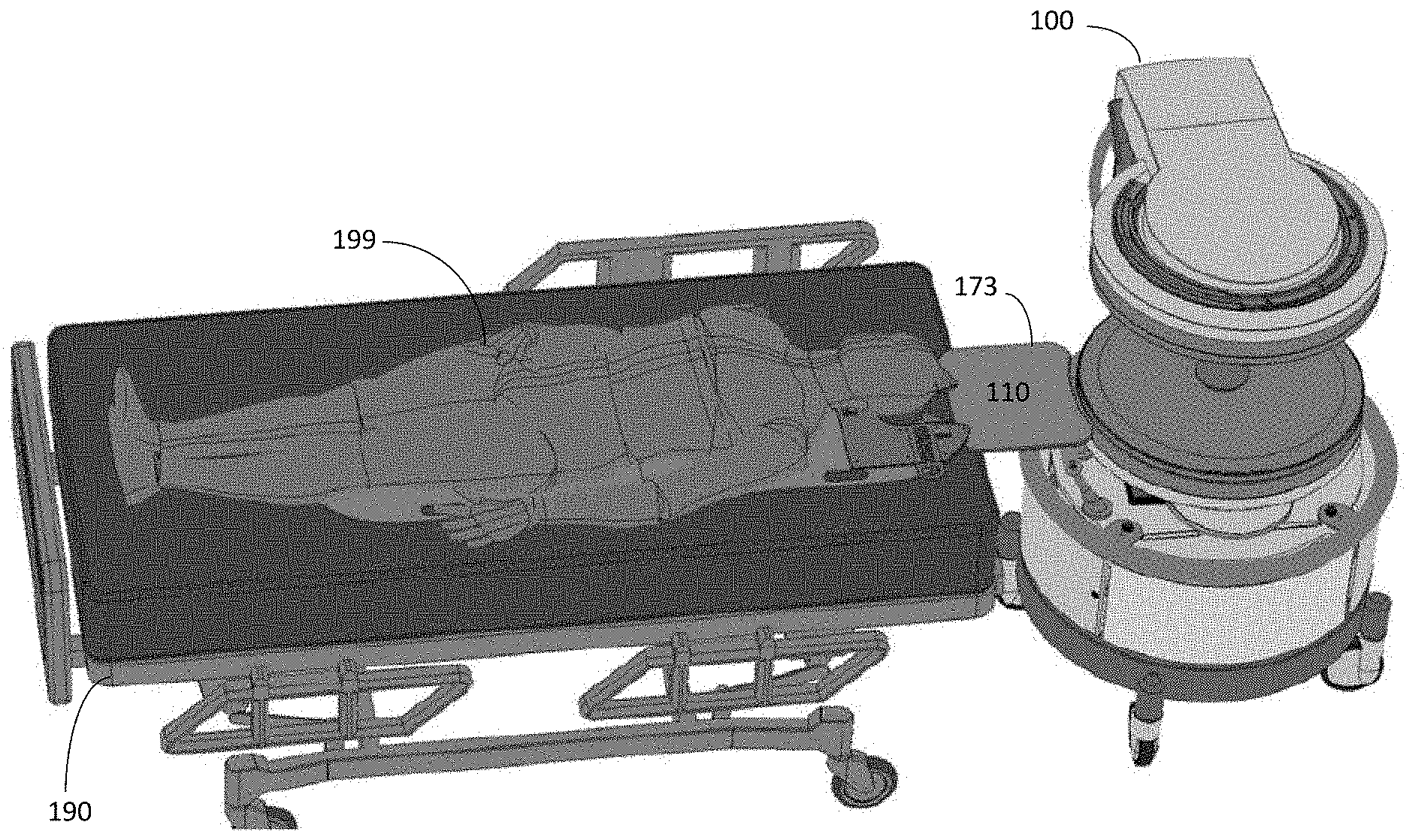
[0034] Imaging a patient from, for example, a standard hospital bed may require positioning target anatomy of the patient within an MRI system located proximate the hospital bed on which the patient is lying. The inventors have developed techniques for facilitating the positioning of a patient within the MRI system for imaging of desired anatomy of the patient from the patient's bed. For example, FIG. 1 illustrates a portable low-field MRI system 100 that has been moved into position proximate a standard hospital bed 190 to perform MRI on a patient 199 who may be confined to the bed for convenience, comfort or stabilization and/or because the patient is unconscious, immobilized or otherwise is not ambulatory or cannot be safely moved. Portable MRI system 100 may be a local installation deployed in an emergency room, operating room, intensive care unit, doctor's office, etc. that can be moved to bed 190, or in some cases, bed 190 can be wheeled to the MRI system. Because of the low-field strengths of MRI system 100, bed 190 can be safely positioned in close proximity to MRI system 100.
[0035] To bridge the gap between bed 190 and MRI system 100, the MRI system may be equipped with a bridge 173 mounted to MRI system 100 to facilitate positioning patient 199 within the imaging region of MRI system 100. Specifically, bridge 173 provides a surface 110 over which patient 199 can be moved so that the patient's anatomy being imaged (e.g., the patient's head) can be positioned within the imaging region of the MRI system. However, the inventors have recognized a number of drawbacks of exemplary bridge 173 illustrated in FIG. 1. For example, as illustrated in FIG. 1, fixed bridge 173 protrudes out from the MRI system, thereby increasing the footprint of the system. As a result, navigating the MRI system down hallways and through doorways is more difficult. Additionally, the useable surface of bridge 173 is limited and the construction of the bridge may not be suitable for heavier patients. As a result, bridge 173 may be difficult to use with larger and/or heavier patients and may not be rated to support the heaviest patients.
[0036] The inventors have recognized the benefits of patient support bridge capable of supporting larger and heavier patients and have appreciated the benefits of such a bridge that can accommodate a range of gaps between the MRI system and a patient bed and/or that provide more overlap between the bridge and the bed. Specifically, for patient comfort, safety and/or to facilitate more convenient positioning of a patient, particularly larger and/or heavier patients, it is desirable to equip a portable MRI system with relatively large dimensioned bridges capable of safely supporting a wide range of patients. However, there are a number of issues associated with the design and development of relatively large dimensioned bridges capable of supporting the weight of larger patients.
[0037] For example, larger bridges increase the footprint of the MRI system even further, making it more difficult (or impossible) to transport the MRI system down hallways and to fit the MRI system through the doorways of the health care facilities in which they are deployed. To address the problem of increased footprint for the MRI system, the inventors have developed a fold-out bridge that can be folded-down to facilitate positioning the patient within the imaging region of the MRI system and to support the patient during an imaging procedure and that can be folded-up during transport of the MRI system so that the MRI system can be more easily moved down hallways and through doorways to the patient.
[0038] Additionally, providing a bridge capable of safely supporting larger, heavier patients requires robust construction. Typically, such patient supports would be constructed using large amounts of metal material capable of withstanding the significant stresses resulting from supporting the weight of heavier patients. However, significant quantities of metal may negatively impact the operation of the magnetic resonance imaging system to which the bridge is attached by distorting the main magnetic field and/or producing substantial eddy currents during operation of the magnetic resonance imaging system that negatively impact image quality. To mitigate this problem, some embodiments include a fold-up bridge in which the metal composition of the bridge is minimized to the extent possible to provide a bridge capable of supporting heavier patient while minimizing the impact on the operation of the magnetic resonance imaging system. Thus, the exemplary fold-up bridges described herein may be capable of supporting large and/or heavy patients safely and securely, thus taking advantage of the benefits of larger dimensioned bridges without significantly impacting the ability to move the MRI system down hallways and through doorways.
[0039] Following below are more detailed descriptions of various concepts related to, and embodiments of, a fold-out bridge that can be moved from a vertical position for stowing during transport of a portable low-field MRI system or when the MRI system is not in use to a horizontal position to facilitate positioning of the patient for point-of-care MRI. It should be appreciated that the embodiments described herein may be implemented in any of numerous ways. Examples of specific implementations are provided below for illustrative purposes only. It should be appreciated that the embodiments and the features/capabilities provided may be used individually, all together, or in any combination of two or more, as aspects of the technology described herein are not limited in this respect or to the specific combinations described.
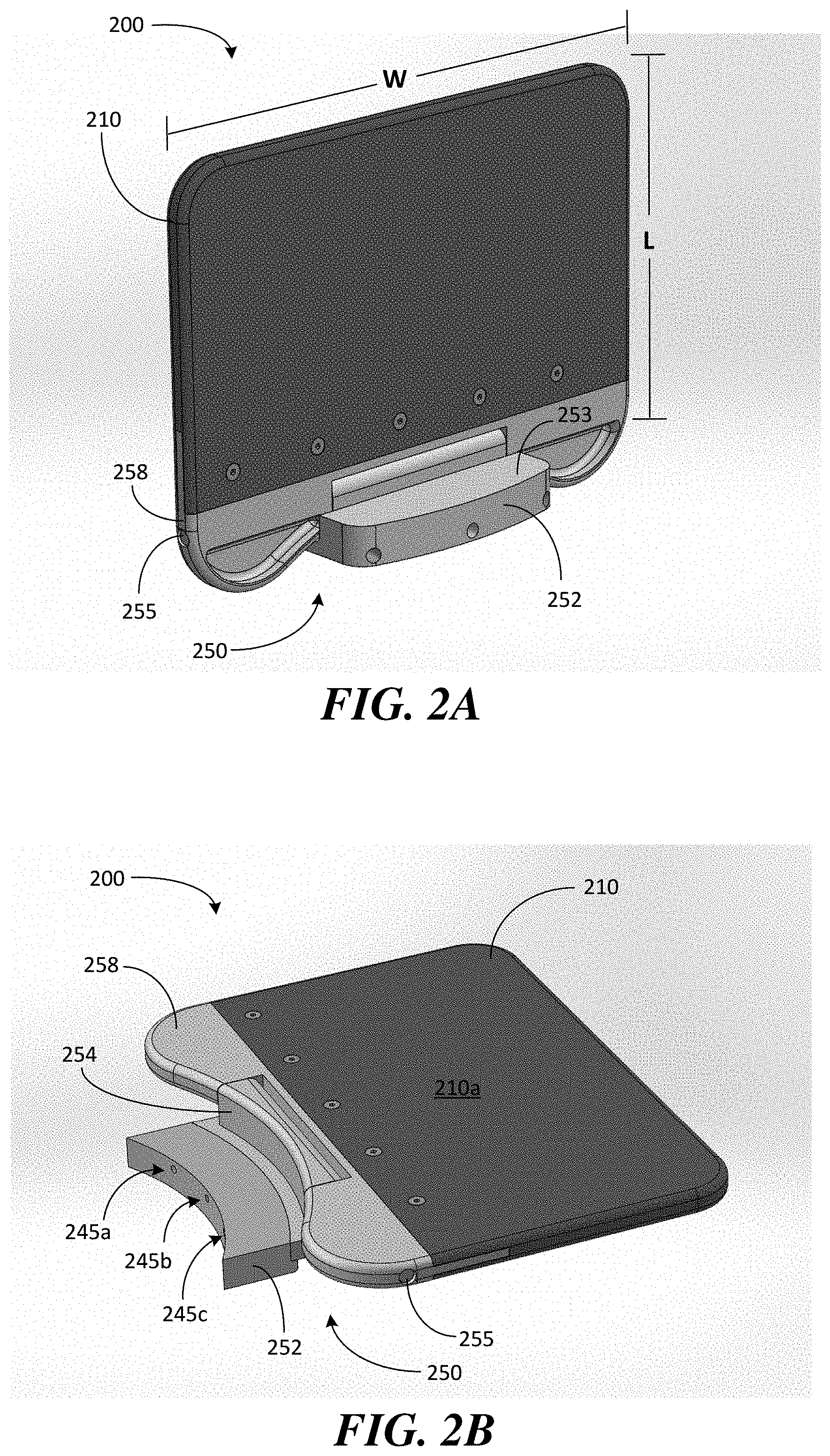
[0040] FIGS. 2A and 2B illustrate an exemplary fold-out bridge for supporting a patient during positioning and imaging, in accordance with some embodiments. Bridge 200 is configured to be placed in a stowed or "folded-up" position (also referred to simply as the "up" or "vertical" position) or placed in an operational or "folded-down" position (also referred to simply as the "down" or "horizontal" position), respectively. Bridge 200 includes a support 210 configured to bridge a gap between the MRI system to which the bridge is attached and a patient support (e.g., a hospital bed) to which the MRI system is proximately located. Support 210 comprises a surface 210a designed to support the patient during positioning and imaging when the bridge is placed in the down position shown in FIG. 2B.
[0041] When bridge 200 is in the down position, surface 210a of support 210 is substantially horizontal to provide support for the patient. Support 210, and particularly surface 210a, may be made of material that reduces friction between a patient and the bridge, such as a smooth plastic, to facilitate positioning of the patient within the imaging region of the MRI system without producing eddy currents during operation of the system. As shown in FIG. 2A, when bridge 200 is in the up position, surface 210a (which is visible in FIG. 2B) of support 210 is substantially vertical so that the support does not add substantially, if at all, to the dimensions of the magnetic resonance imaging system (e.g., when the bridge is in the up position, the bridge does not increase the outer perimeter or footprint of the system).
[0042] Bridge 200 comprises a hinge 250 that allows support 210 to pivot from the up position to the down position and vice versa (e.g., hinge 250 allows bridge 200 to be moved between the positions illustrated in FIGS. 2A and 2B). According to some embodiments, hinge 250 comprises a shaft 255 that allows support 210 to pivot or rotate from the vertical position shown in FIG. 2A to the horizontal position shown in FIG. 2B and vice versa. Specifically, exemplary bridge 200 comprises a base 252 and a pivot portion 258 through which shaft 255 passes to allow the pivot portion 258 to rotate about the shaft when folding up and folding down the bridge.
[0043] Base 252 is configured to attach to the MRI system and includes stop 253 (see FIG. 2A) and stop 254 (see FIG. 2B) that provide end stops to prevent further pivoting of the bridge when the horizontal position and vertical position are reached, respectively. Base 252 further comprises counter-bores 245 (e.g., bores 245a, 245b and 245c) to accommodate bolts that allow bridge 200 to be securely attached to the MRI system. For example, according to some embodiments, base 252 is constructed with three counter-bores to accommodate respective M8 bolts that securely attach the base of the bridge directly to the B.sub.0 magnet of the MRI system (e.g., as shown in FIGS. 6A-6C discussed below). Bolting the bridge to the MRI system in this manner contributes to the bridge being able to withstand the torque produced by the weight of a patient.
[0044] As discussed above, the inventors have recognized the benefits of providing a bridge that can accommodate larger (e.g., wider) and heavier patients and that can bridge larger gaps between a patient bed and the MRI system and/or that provide additional overlap with the patient bed when placed in the down position. According to some embodiments, a fold-out bridge is constructed having a width of between 12 and 36 inches and a length of between 8 and 24 inches. For example, exemplary bridge 200 has a width W of at least 24 inches and a length L of at least 12 inches to provide a relatively large surface to accommodate a variety of patients and to bridge a variety of gaps. The length of the bridge refers to the dimension generally in a direction outward from the MRI system.
[0045] By increasing the length of the bridge, larger gaps can be bridged and/or larger overlaps with a patient bed can be achieved. The width of the bridge refers to the dimension generally in a direction tangent to the MRI system. By increasing the width of the bridge, wider patients may be more comfortably accommodated and supported. Hospital equipment for acute care is often rated to accommodate patients weighing 500 lbs. (e.g., hospital beds are often rated to support 500 lb. patients). According to some embodiments, bridge 200 is also rated for 500 lb. patients and may be constructed to have a safety factor of at least 2.5 (i.e., that have a yield strength of at least 2.5 times the rating). According to some embodiments, bridge 200 is rated for 500 lb. patients and is constructed to have a safety factor of 4.0 or more, examples of which are described in further detail below.
[0046] FIG. 3 illustrates components of a fold-out bridge 300 to illustrate exemplary construction details, in accordance with some embodiments. Similar to bridge 200 described above, bridge 300 includes a support 210 having a surface 210a configured to support a patient during positioning and imaging. Bridge 300 further includes a hinge 250 comprising base 252 and pivot portion 258 that, when coupled together via shaft 255, allows support 210 to pivot from a vertical position to a horizontal position and vice versa. For exemplary bridge 300, support 210 may be coupled to pivot portion 258 using a tongue-and-groove interface. Specifically, support 210 includes a groove 217 configured to receive tongue 257, which extends out from pivot portion 258. To couple the support to the pivot portion, tongue 257 may be inserted into groove 217 and screwed or bolted into place to secure support 210 to pivot portion 258.
[0047] To construct hinge 250, pivot portion 258 comprises shoulders 259a and 259b between which is provided gap 263 sized to accommodate base 252. Shoulders 259a, 259b and stop 254 of base 252 include cooperating bores 265 through which shaft 255 is inserted to allow support 210 to pivot between the up and down positions. When constructed, shaft 255 is secured within bores 265 of the base and pivot portions with nuts 266a and bolts 266b at both ends of the shaft. Thus, pivot portion 258 is allowed to rotate about the shaft so that support 210 can be moved from the vertical position (i.e., in which planar surface 210a is substantially vertical) when not in use to the horizontal position (i.e., in which the planar surface 210a is substantially horizontal) to facilitate positioning a patient within the imaging region of the MRI system and to support the patient during imaging. As discussed above, bridge 300 can be bolted to the MRI system via bolt holes 245a-c (e.g., bolted to the lower B.sub.0 magnet of the MRI system so that it is level with the patient surface within the imaging region of the MRI system as shown in FIGS. 6A-C discussed below).
[0048] Bridge 300 may further include ball plungers 280a and 280b that facilitate holding the bridge in the vertical position when the bridge is not being used. For example, ball or spring plungers 280a and 280b may be positioned on either side of base 252 to interact with shoulders 259a and 259b of pivot portion 258. Specifically, to move bridge 300 from the vertical to the horizontal position, the shoulders of the pivot portion must first overcome the resistance provided by the spring loaded ball plungers (i.e., to pivot bridge 300 out of the vertical position, shoulders 259a and 259b must first move over the ball plungers, which provide a counter-resistance to the initial rotation of the pivot portion). Accordingly, because an initial force exceeding the resistance of the ball plungers is needed to move the bridge out of the vertical position, a measure of safety is provided by reducing the chances that bridge 300 will unintentionally fall from the vertical position to the horizontal position. Bridge 300 may also include rubber stoppers 293 configured to fit within corresponding holes provided in stop 253 of base 252 to reduce noise produced when shoulders 259a, 259b contact stop 253 when the bridge is moved to the down position and/or to absorb some of the impact of the bridge should the bridge fall or if the bridge is roughly handled during transition to the horizontal position.
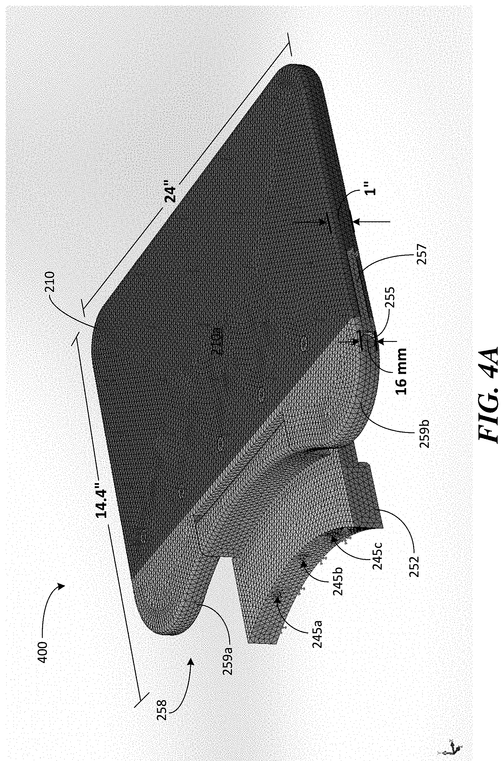
[0049] FIG. 4A illustrates a model of a fold-out bridge 400 constructed to support larger and/or heavier patients, in accordance with some embodiments. The model illustrated in FIG. 4A was used to perform a number of performance tests on exemplary bridge 400 designed to provide a relatively large surface to facilitate patient positioning and constructed to support heavier patients (e.g., to achieve a 500 lb. rating). The following dimensions, materials and construction details are provided merely as description of the exemplary bridge 400 on which stress tests were performed and do not limit the aspects of a fold-out bridge in this respect. In particular, different dimensions, materials and designs may be used to construct a fold-out bridge and different aspects of a fold-out bridge discussed herein may be used in different combinations. Bridge 400 illustrates one example of a suitable fold-out bridge capable of supporting larger and/or heaving patients and that provides a relatively large surface to facilitate patient positioning and support.
[0050] Bridge 400 is provided with a support 210 having a relatively large surface area, for example, a width of 24 inches and a length of 14.4 inches measured from the far side of support 210 to the center of the curved interface of base 252 where bridge 400 is bolted to the MRI system (i.e., at counter-bore 245b). Support 210 is formed, at least in part, by a 1 inch thick plastic platform that provides a surface 210a over which a patient can be moved to position the patient within the MRI system. Similar to the construction of exemplary bridge 300, pivot portion 258 is coupled to support 210 via a tongue-and-groove interface and coupled to the base via a 16 mm diameter shaft 255 inserted through shoulder portions 259a and 259b. For exemplary bridge 400, shoulders 259a and 259b are constructed of metal (e.g., aluminum) and tongue portion 257 is constructed of plastic (or other non-metallic material). Base 252 may be constructed from steel and may comprise three counter-bores 245a-c for bolting bridge 400 to the B.sub.0 magnet of the MRI system (e.g., using three corresponding M8 bolts). In this way, components of bridge 400 that undergo the greatest amount of stress may be constructed of metal and components that undergo less stress may be made of plastic (or other non-metallic material) to minimize eddy current production when the MRI system is operated while providing a bridge with robust construction.
[0051] To evaluate the performance of exemplary bridge 400, stress tests were simulated on the model of bridge 400 to ensure that the design achieves a 500 lb. rating with a safety factor suitable for patient support equipment. In particular, using the above described construction details, a mesh was applied to the model of bridge 400 as shown in FIG. 4A and the stresses resulting from the weight of a patient were simulated via finite element analysis. The weight that bridge 400 is required to support for a 500 lb. patient was obtained from the International Electrotechnical Commission (IEC) 60601-1 International Standard. Specifically, IEC 60601-1 establishes a number of safety requirements and performance standards for medical equipment.
[0052] Figure A.19 of IEC 60601-1, which is reproduced herein as FIG. 4D, shows an example of human body mass distribution that was used to determine how the weight of a 500 lb. patient is distributed over the patient support surface of the exemplary bridges described herein. As shown in FIG. 4D, Figure A.19 of IEC 60601-1 specifies the length dimension (in millimeters) and the percent of a patient's body mass that is contributed by significant segments of the human body lying in a supine position. Specifically, the head accounts for 7.4% of the mass of the patient, the torso accounts for 40.7%, the upper arms together account for 7.4% and the lower arms another 7.4%, the upper legs account for 22.2% and the lower legs account for 14.8%. When a patient is positioned within a portable MRI system, the head lies within the imaging region and is supported by the MRI system (e.g., by the helmet on which the transmit/receive coils are located) so that the bridge need support at least some portion of the torso, shoulder and arm portions of the body. The full contribution of the torso and the upper arms is approximately 50% (48.1%) of the body mass of the patient. Accordingly, in approximate numbers, for a bridge having a 500 lb. rating and a safety factor of 1, the bridge would be required to support 250 lbs. (i.e., 50% of the patient's total weight). For a safety factor of 2.5, the bridge would need to support 625 lbs (i.e., 50% of the patient's weight times 2.5) and, for a safety factor of 4, the bridge would need to support 1000 lbs. (i.e., 50% of the patients weight times 4).
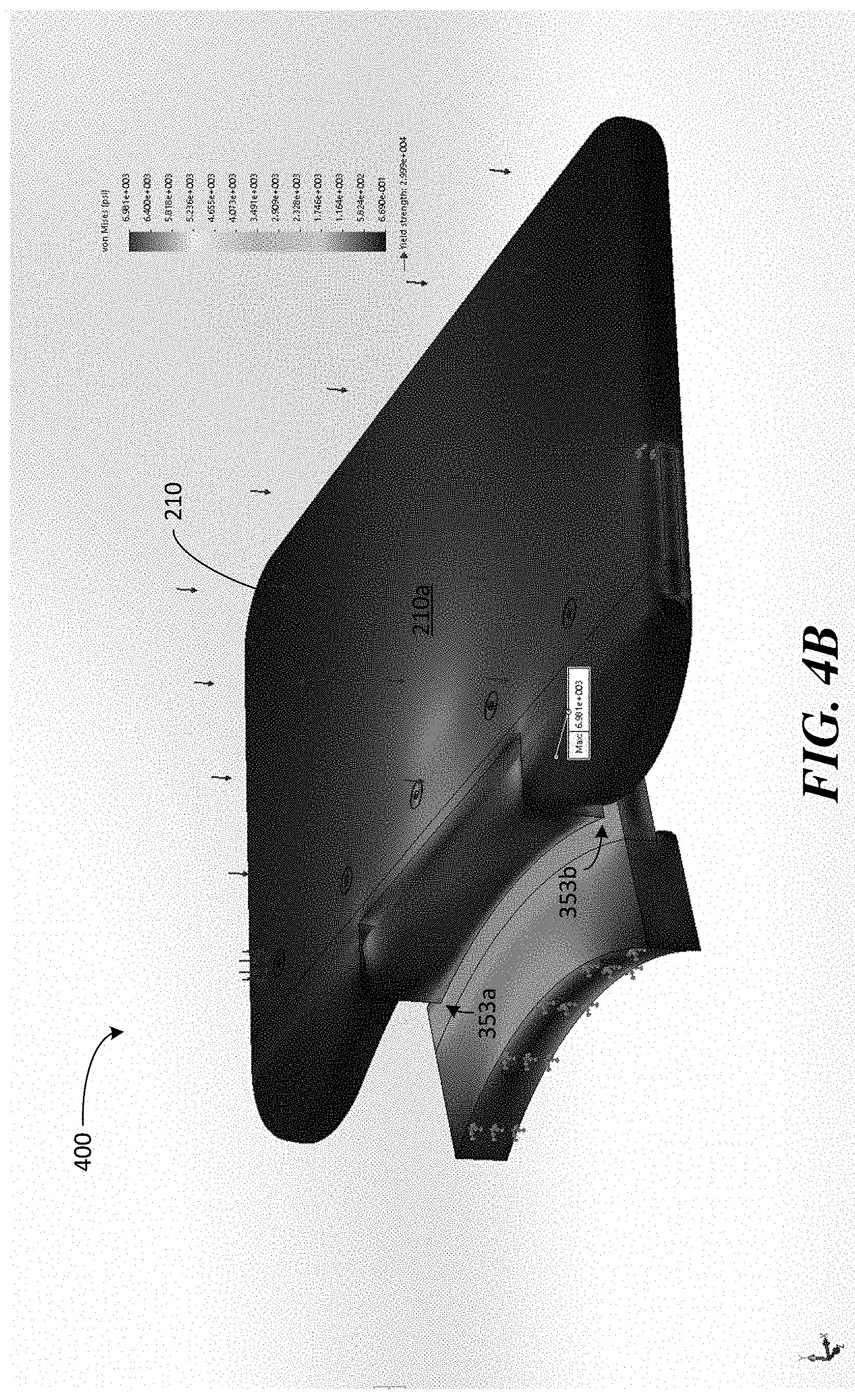
[0053] To evaluate bridge 400 for a 500 lb. rating, the stresses on bridge 400 resulting from a 500 lb. patient were simulated by distributing 250 lbs. of weight over the surface of the bridge (i.e., 50% of the patient's weight that the bridge needs to support), as shown by the downward arrows in FIGS. 4A-4C. Using the materials and dimensions discussed above, this distributed weight produced the stress plot shown in FIG. 4B. A maximum stress of 6,981 psi resulted at the corners of the base indicated by arrows 353a and 353b. The yield strength of exemplary bridge 400 was also assessed to evaluate the maximum stress that bridge 400 can withstand. The yield strength of bridge 400 was determined to be 30,000 psi. Thus, exemplary bridge 400 achieves a 500 lb. rating with a safety factor of 4.3. Specifically, the yield strength of the bridge is 4.3 times greater than the maximum stress resulting from simulating the forces applied on bridge 400 by a 500 lb. patient.
[0054] FIG. 4C illustrates a deflection plot showing the deformation of the bridge under the 250 lb. simulated weight. The maximum deflection of the bridge resulting from the simulation was 1.5 mm at the far end of support 210. In particular, the arrows show the location of the bridge without the simulated force applied. In FIGS. 4B and 4C, the displacement resulting from the applied 250 lbs. is shown at 36.4 scale to exaggerate the displacement so that it can be visualized (i.e., the actual displacement is 36.4 times smaller than it appears in the plots shown in FIGS. 4B and 4C). Thus, a 250 lb. weight distributed across bridge 400 to simulate the stresses resulting from a 500 lb. patient resulted in a maximum displacement of 1.5 mm at end 210b of support 210.
[0055] The inventors have recognized that some embodiments of a fold-out bridge may be relatively large and heavy, particularly when dimensioned and constructed to facilitate positioning and support of larger, heavier patients. For example, an exemplary bridge may be dimensioned to have a length of between 1 and 2 feet or more and a width of between 1.5 and 2.5 feet or more, resulting in bridges that can weigh between 8 and 15 lbs. or more. Larger, heavier bridges have the potential to injure if the bridge accidentally falls from the vertical position. To prevent a bridge from being able to free fall, the inventors have developed a counter-balance mechanism configured to slow the rate at which the bridge can transition from the up position to the down position. The counter-balance mechanism provides an additional safety precaution that protects patients and medical personnel from possible injury, as discussed in further detail below.
[0056] FIGS. 5A and 5B illustrate components for a bridge 500, in accordance with some embodiments. Exemplary fold-out bridge 500 may comprise many of the same components described in connection with bridge 300 illustrated in FIG. 3 and/or bridge 400 illustrated in FIGS. 4A-C. However, bridge 500 includes a counter-balance mechanism configured to slow the rate at which fold-out bridge 500 can pivot to the horizontal position. According to some embodiments, the counter-balance mechanism comprises torsion springs 275a and 275b. Torsion springs 275a and 275b are configured to fit over respective ends of shaft 555. Each torsion spring 275a, 275b is configured with end portions 276a and 276b that protrude out from the spring in the direction of the shaft, as can be seen best in the magnified portion of one end of the counter-balance component illustrated in FIG. 5B.
[0057] In particular, end portions 276a are arranged in the direction of the axis of shaft 555 and positioned on the perimeter of the respective torsion spring and are configured to fit into a corresponding indexing hole 278 provided in indexing components 277a, 277b. End portions 276b are similarly arranged and configured to fit into respective indexing holes 278 provided in shoulders 559a and 559b of pivot portion 558. Specifically, indexing components 277a, 277b comprise a plurality of indexing holes 278 around the perimeter (see e.g., exemplary indexing holes 278a and 278b illustrated in FIG. 5B) to accommodate end portions 276a. Shoulders 559a and 559b comprise notches 556a and 556b to accommodate respective torsion springs. Notches 556a and 556b comprise bores 265 through which shaft 555 passes and further comprise indexing holes 278 into which end portions 276b are inserted (as best seen by indexing hole 278d provide next to bore 265 within notch 556b). For example, end portion 276b of each torsion spring 275a, 275b fits into the respective indexing holes 278c and 278d so that the torsion spring is coupled to indexing component 277 at one end and pivot component 558 at the other end.
[0058] Shaft 555 includes flats 555a and 555b configured to fit into respective indexing components 277a and 277b. Specifically, flats 555a and 555b are configured to be inserted into slots 279 provided in respective indexing components 277a, 277b (as seen best in the magnified view shown in FIG. 5B) and secured by screws 566a and 566b at opposite ends of shaft 555. To facilitate operation of the counter-balance mechanism, corresponding screw holes 236a and 236b are provided through stop 254 of base 252 and into shaft 555, respectively, to accommodate screw 235 to hold shaft 255 in place. Specifically, screw 235 is inserted through screw hole 236a in the base and into screw hole 236b in shaft 555 to prevent the shaft from rotating when pivot portion 558 rotates during transitions between the up and down positions. Preventing shaft 255 from rotating ensures that rotation of pivot portion 558 causes the torsion springs 275a, 275b to wind or tighten to slow the rate at which pivot portion 558 can rotate, as discussed in further detail below. Sleeves 260a and 260b cover respective torsion springs 275a and 275b when the bridge is assembled.
[0059] When constructed as described above, shaft 555 is fixed in place and prevented from rotating by inserting the shaft through bores 265 and into slots 279 of the respective indexing portions 277a, 277b and screwing the shaft in place via screws 566a, 566b and 235. By inserting end portions 276a and 276b of the torsion springs 275a, 275b into the indexing portions 277a, 277b and pivot portion 558, respectively, rotation of pivot portion 558 from the vertical position to the horizontal position causes the torsion springs to tighten due to the fixed connection between end portions 276a to the indexing components 277a, 277b (which does not rotate) and the fixed connection between end portions 276b and the indexing holes 278c, 278d in notches 556a, 556b, respectively, by which end portions 276b are rotated along with the pivot portion 558. That is, because indexing holes 278c and 278d and end portions 276b are aligned in the direction of the shaft axis but are positioned off-axis, the rotation of the pivot portion causes the torsion spring to tighten as indexing holes 278c and 278d rotate about the axis of the shaft. Thus, when the bridge pivots from a vertical to a horizontal position, the twisting of the torsion springs slows the rotation of support 210 to prevent the bridge from rotating in free fall. The spring constant of the torsion springs can be selected to achieve the desired level of control of the rate at which the bridge is allowed to transition between the up and down positions. In this manner, bridge 500 includes a counter-balance mechanism providing an additional safety mechanism to reduce the chances of injury when using a fold-out bridge.
[0060] As discussed above, the exemplary fold-out bridges described herein are configured to attach to a portable magnetic resonance imaging system to facilitate positioning and supporting a patient during point-of-care MRI. FIGS. 6A, 6B and 6C illustrate a portable low-field MRI system to which the exemplary fold-out bridges described herein can be attached. Specifically, portable low-field MRI system 1000 can be deployed in virtually any environment to image patients, for example, from a standard hospital bed located in emergency rooms, intensive care units, operating rooms, neonatal units, clinics, primary care offices, recovery units, etc. where conventional MRI is typically not available. Exemplary fold-out bridge may be configured to facilitate positioning and support of large, heavy patients without substantially increasing the footprint of the MRI system by virtue of being capable of being stowed in the vertical position during transport or when not in use and folded-down when needed to perform, for example, point-of-care MRI.
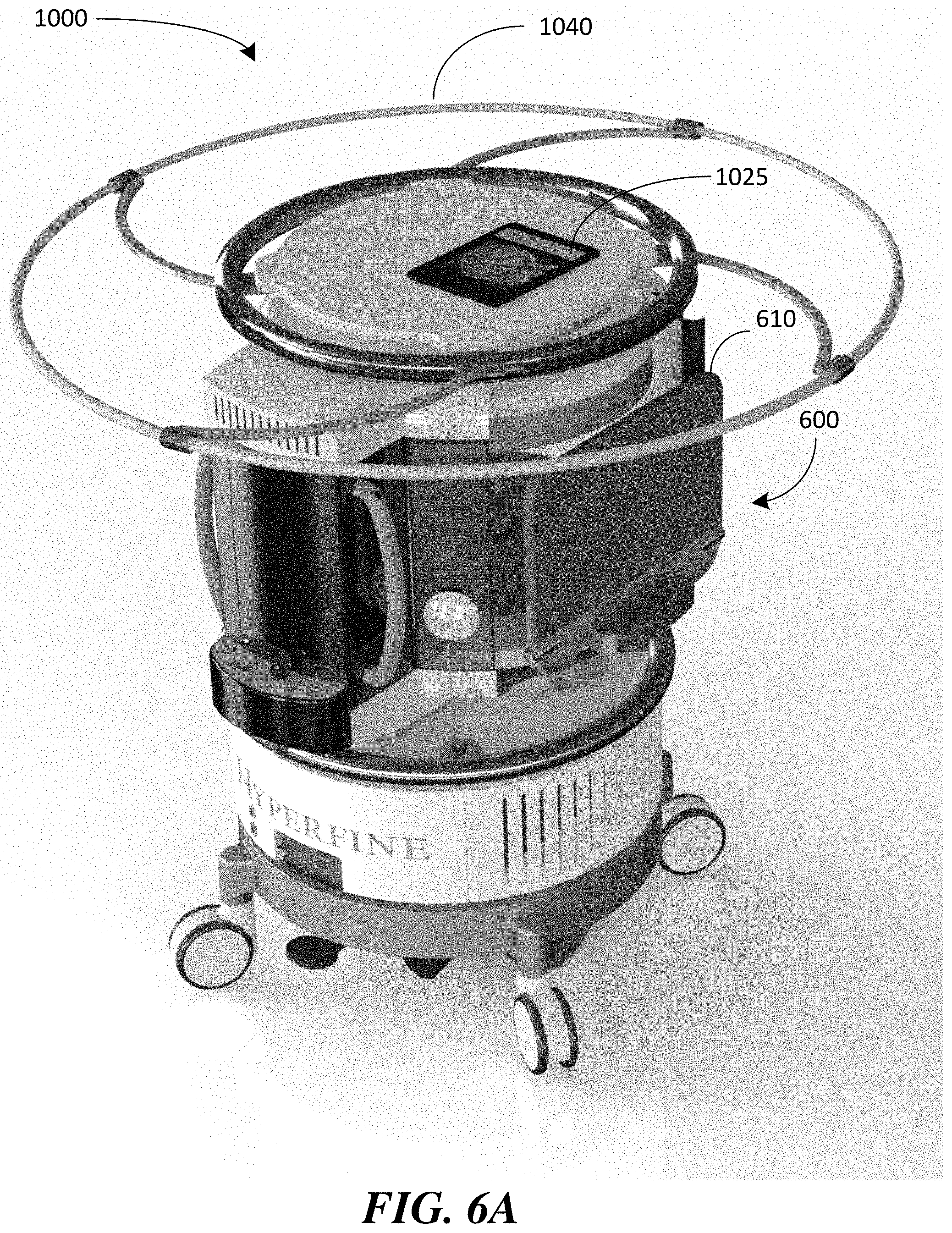
[0061] In particular, to facilitate transporting portable MRI system 1000 to locations at which MRI is needed, portable MRI system 1000 is equipped with a fold-out bridge 600, which may include any one or more of the features of a fold-out bridge described herein. FIG. 6A illustrates bridge 600 configured in its up position so that support 610 is substantially vertical and does not add significantly (or at all) to the footprint of the MRI system. As a result, bridge 600 does not impede moving the portable MRI system down hallways and through doorways. FIG. 6A also illustrates a deployable guard 1040 in its deployed position to indicate the 5-Gauss line for the MRI system as its being transported or when it is stored away or otherwise not in use. As discussed in U.S. application Ser. No. 16/389,004, titled "Deployable Guard for Portable Magnetic Resonance Imaging Device," filed on Apr. 19, 2019, which is herein incorporated by reference in its entirety, the guard can be deployed to demarcate the physical boundary within which the magnetic field is above a specified field strength to provide a visual signal when the MRI system is being moved to a different location. In addition, as illustrated in FIG. 6B, when bridge 600 is up, the bridge provides a barrier to the imaging region of the MRI system where the magnetic field is strongest.
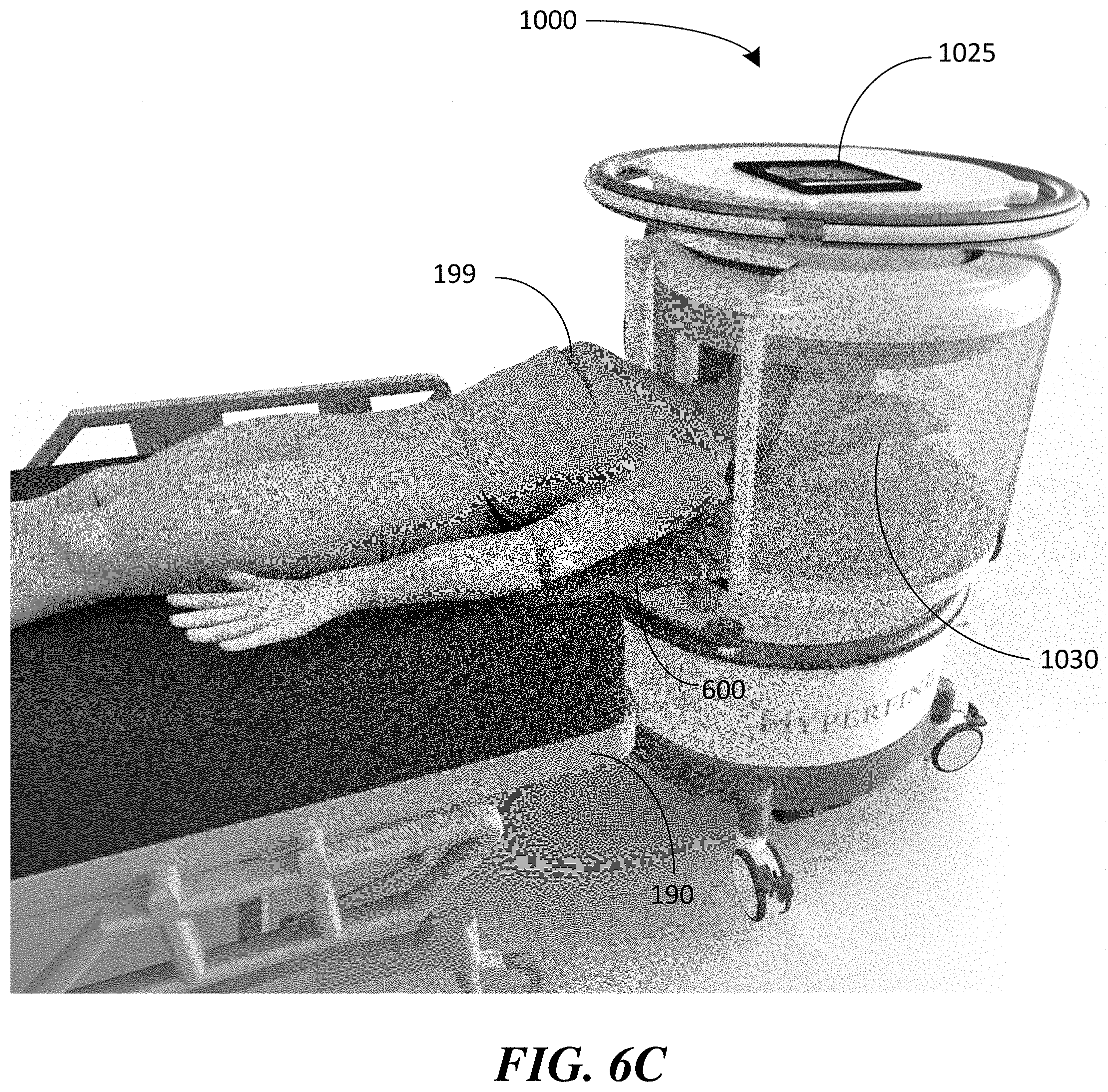
[0062] FIG. 6B illustrates portable MRI system 1000 with bridge 600 configured in the down position and FIG. 6C illustrates bridge 600 deployed in the down position to bridge the gap between patient bed 190 and MRI system 1000 to allow patient 199 to be positioned within the imaging region of the MRI system and to support patient 199 during imaging. As discussed above, bridge 600 may be bolted to the B.sub.0 magnet to secure the bridge to the MRI system. For example, as shown in FIG. 6B, portable MRI system 1000 comprises a B.sub.0 magnet 1005 that includes at least one first permanent B.sub.0 magnet 1010a and at least one second permanent B.sub.0 magnet 1010b magnetically coupled to one another by a ferromagnetic yoke 1020 configured to capture and channel magnetic flux to increase the magnetic flux density within the imaging region 1065 (field of view) of the MRI system. For exemplary MRI system 1000, bridge 600 is bolted to the lower magnet 1010b so that when it is deployed (i.e., positioned in the down position as shown in FIGS. 6B and 6C), support 610 provides a continuation of the planar surface 1015 of the magnet housing to facilitate positioning the patient within imaging region 1065 and providing relatively level support to the patient during imaging. FIG. 6B also illustrates a conveyance mechanism 1080 of MRI system 1000 that facilitates moving the MRI system from one location to another, as discussed in further detail below.
[0063] FIG. 6C illustrates patient 199 positioned within the imaging region of MRI system 1000 for imaging of the patient's head from hospital bed 190. As shown, once the patient is positioned with the imaging region and during the imaging process, the patient's head is supported by helmet 1030 (which comprises radio frequency transmit and receive coils), at least a portion of the patient's torso and arms are supported by fold-out bridge 600 and the remainder of the patient's weight is supported by patient bed 190. As discussed above, some embodiments of a fold-out bridge are dimensioned and constructed to support large and heavy patients. For example, bridge 600 may be rated for a 500 lb. patient with a safety factor of 2.5 or more. According to some embodiments, bridge 600 may be rated for a 500 lb. patient with a safety factor of 4.0 or more (e.g., a safety factor of 4.3), for example, using the various exemplary bridge constructions described above in connection with any of exemplary bridges 300, 400 or 500.
[0064] The inventors have recognized that a fold-out bridge may also be used as an additional safety feature that ensures that the portable MRI system cannot be accidentally moved when the bridge is supporting a patient and/or otherwise in use. As discussed above, portable MRI system 1000 includes a conveyance mechanism configured to allow the portable MRI system to be transported to desired locations. Referring to FIG. 6B, portable MRI system 1000 comprises a conveyance mechanism 1080 having a drive motor 1086 coupled to drive wheels 1084. Conveyance mechanism 1080 may also include a plurality of castors 1082 to assist with support and stability as well as to facilitate transport of the MRI system. In this manner, conveyance mechanism 1080 provides motorized assistance in transporting MRI system 1000 to desired locations.
[0065] According to some embodiments, conveyance mechanism 1080 includes motorized assistance controlled using a controller (e.g., a joystick or other controller that can be manipulated by a person) to guide the portable MRI system during transportation to desired locations. According to some embodiments, the conveyance mechanism comprises power assist means configured to detect when force is applied to the MRI system and to engage the conveyance mechanism to provide motorized assistance in the direction of the detected force. For example, rail 1050 illustrated in FIG. 6B may be configured to detect when force is applied to the rail (e.g., by personnel pushing on the rail) and engage the drive motor to provide motorized assistance to drive the wheels in the direction of the applied force. As a result, a user can guide the portable MRI system with the assistance of the conveyance mechanism that responds to the direction of force applied by the user. The drive motor may be operated in other ways, such as via buttons, roller ball or other suitable mechanism located on the MRI system, or using touch screen controls on a mobile computing device 1025 communicatively coupled to the MRI system, as the aspects of motorized control is not limited in this respect.
[0066] Motorized transport has the potential for being accidentally engaged, resulting in unintentional movement of the MRI system that could injure a patient or medical personnel. For example, medical personnel may forget to turn off the motorized transport or motorized assist after the MRI system has been positioned for imaging (e.g., transported to a location adjacent a patient's hospital bed). Accidental contact with the rail or unintentional interaction with a joystick or other on-system or mobile control of the motor drive could cause the MRI system to move while a patient is positioned within the imaging region of the system or during positioning of the patient prior to imaging. Such accidental movement of the MRI system has the potential to injure the patient or medical personnel. To prevent unintentional movement of the MRI system, the inventors have developed a lock-out mechanism that disables any motorized conveyance components when the bridge is transitioned to the down position and is supporting sufficient patient weight. For example, the lock-out mechanism may include a switch that disables the motor drive when actuated by the bridge. According to some embodiments, a sensor that detects weight on the support of the bridge is provided and, in response to detecting the presence of a patient, disables the drive motor and/or other components involved in motorized transport or motorized assist to ensure that the MRI system is immobilized when the system is supporting a patient.
[0067] An exemplary lock-out switch configured to disable the motor drive of the MRI system is described in connection with FIG. 5A. As discussed above, rubber plugs 293 can be used to absorb noise and reduce wear when the bridge is placed in the horizontal position. Alternatively, or in addition to the plugs, the bores formed in stop 253 of the base into which the plugs are positioned may also include an electromechanical lock-out switch that, when activated, disables the motor drive of the MRI system. For example, one or more springs may be placed in the bores (or otherwise coupled to the bridge) such that the weight of the patient causes compression of the springs to actuate a switch that locks-out the motor drive. The spring(s) may be selected such that the weight of the bridge when placed in the down position does not compress (or insufficiently compresses) the spring so that the bridge itself does not lock out the motor drive. However, the additional weight of a patient causes the springs to compress sufficiently to activate a switch that disables the motor drive so that the portable MRI system cannot be accidentally moved when a patient is present.
[0068] According to some embodiments, the weight of the bridge itself when placed in the horizontal position is sufficient to engage the lock-out switch and disable the motor drive. In this way, moving the bridge from the vertical to the horizontal position will immobilize the MRI system and prevent unintentional movement of the MRI system. It should be appreciated that other types of switches may be used to detect the present of a patient on the bridge and/or detect when the bridge has been moved from the vertical to the horizontal position to disable the motor drive of the system, as the aspects are not limited in this respect. The sensor that detects patient presence and/or detects when the bridge has been placed in the horizontal position to engage the lock-out switch may be mechanical, electrical, electromechanical, pneumatic, hydraulic or any combination thereof.
[0069] Thus, low-field MRI system 1000 equipped with fold-out bridge 600 can be used to perform point-of-care MRI on a patient, including large and heavy patients. For example, to perform point-of-care MRI on a patient from a standard medical bed, the MRI system and the bed can be positioned proximate one another. In some embodiments, the MRI system is portable and can be moved into position near the hospital bed by medical personnel pushing the MRI system into place and/or using a motor drive conveyance system to move the MRI system into position. In some instances, the MRI system may need to be transported from another room or unit within the hospital. In other instances, the MRI system may already be located in the same room as the patient and need only be moved next to the bed of the patient. In other circumstances, a hospital bed is transported to the MRI system and moved into place proximate the MRI system for imaging. During the positioning of the MRI system and the patient bed near one another, a fold-out bridge attached to the MRI system may be positioned in the vertical or up position (e.g., in the vertical position illustrated in FIG. 6A) to facilitate transport of the system down hallways and/or through doorways and/or to facilitate positioning the MRI system and the bed in close proximity (e.g., positioning the MRI system and the foot or head of the bed adjacent one another).
[0070] Once the MRI system and the bed are positioned proximate one another, the fold-out bridge may be moved from the vertical position to a horizontal position so that the bridge at least partially overlaps the bed (e.g., the fold-out bridge 600 may be moved from the vertical position illustrated in FIG. 6A to the horizontal position illustrated in FIGS. 6B and 6C). The fold-out bridge then provides a surface that bridges the gap between the MRI system and the bed over which the patient can be moved. For example, the portion of anatomy of the patient to be imaged may be positioned within an imaging region of the MRI system via the bridge and the bridge may provide support for the patient during and after positioning the patient within the imaging region. According to some embodiments, the fold-out bridge comprises a lock-out switch that is engaged when sufficient patient weight is placed on the bridge, thus disabling the motor drive and/or any motorized components of the conveyance system to ensure that the MRI system is immobilized. After positioning the patient within the MRI system, at least one magnetic resonance image of the portion of the anatomy of the patient may be acquired while the patient is at least partially supported by the bed and at least partially support by the bridge (e.g., as shown in FIG. 6C). In this way, point-of-care MRI may be performed.
[0071] Having thus described several aspects and embodiments of the technology set forth in the disclosure, it is to be appreciated that various alterations, modifications, and improvements will readily occur to those skilled in the art. Such alterations, modifications, and improvements are intended to be within the spirit and scope of the technology described herein. For example, those of ordinary skill in the art will readily envision a variety of other means and/or structures for performing the function and/or obtaining the results and/or one or more of the advantages described herein, and each of such variations and/or modifications is deemed to be within the scope of the embodiments described herein. Those skilled in the art will recognize, or be able to ascertain using no more than routine experimentation, many equivalents to the specific embodiments described herein. It is, therefore, to be understood that the foregoing embodiments are presented by way of example only and that, within the scope of the appended claims and equivalents thereto, inventive embodiments may be practiced otherwise than as specifically described. In addition, any combination of two or more features, systems, articles, materials, kits, and/or methods described herein, if such features, systems, articles, materials, kits, and/or methods are not mutually inconsistent, is included within the scope of the present disclosure.
[0072] The above-described embodiments can be implemented in any of numerous ways. One or more aspects and embodiments of the present disclosure involving the performance of processes or methods may utilize program instructions executable by a device (e.g., a computer, a processor, or other device) to perform, or control performance of, the processes or methods. In this respect, various inventive concepts may be embodied as a computer readable storage medium (or multiple computer readable storage media) (e.g., a computer memory, one or more floppy discs, compact discs, optical discs, magnetic tapes, flash memories, circuit configurations in Field Programmable Gate Arrays or other semiconductor devices, or other tangible computer storage medium) encoded with one or more programs that, when executed on one or more computers or other processors, perform methods that implement one or more of the various embodiments described above. The computer readable medium or media can be transportable, such that the program or programs stored thereon can be loaded onto one or more different computers or other processors to implement various ones of the aspects described above. In some embodiments, computer readable media may be non-transitory media.
[0073] The terms "program" or "software" are used herein in a generic sense to refer to any type of computer code or set of computer-executable instructions that can be employed to program a computer or other processor to implement various aspects as described above. Additionally, it should be appreciated that according to one aspect, one or more computer programs that when executed perform methods of the present disclosure need not reside on a single computer or processor, but may be distributed in a modular fashion among a number of different computers or processors to implement various aspects of the present disclosure.
[0074] Computer-executable instructions may be in many forms, such as program modules, executed by one or more computers or other devices. Generally, program modules include routines, programs, objects, components, data structures, etc. that perform particular tasks or implement particular abstract data types. Typically the functionality of the program modules may be combined or distributed as desired in various embodiments.
[0075] Also, data structures may be stored in computer-readable media in any suitable form. For simplicity of illustration, data structures may be shown to have fields that are related through location in the data structure. Such relationships may likewise be achieved by assigning storage for the fields with locations in a computer-readable medium that convey relationship between the fields. However, any suitable mechanism may be used to establish a relationship between information in fields of a data structure, including through the use of pointers, tags or other mechanisms that establish relationship between data elements.
[0076] The above-described embodiments of the present invention can be implemented in any of numerous ways. For example, the embodiments may be implemented using hardware, software or a combination thereof. When implemented in software, the software code can be executed on any suitable processor or collection of processors, whether provided in a single computer or distributed among multiple computers. It should be appreciated that any component or collection of components that perform the functions described above can be generically considered as a controller that controls the above-discussed function. A controller can be implemented in numerous ways, such as with dedicated hardware, or with general purpose hardware (e.g., one or more processor) that is programmed using microcode or software to perform the functions recited above, and may be implemented in a combination of ways when the controller corresponds to multiple components of a system.
[0077] Further, it should be appreciated that a computer may be embodied in any of a number of forms, such as a rack-mounted computer, a desktop computer, a laptop computer, or a tablet computer, as non-limiting examples. Additionally, a computer may be embedded in a device not generally regarded as a computer but with suitable processing capabilities, including a Personal Digital Assistant (PDA), a smartphone or any other suitable portable or fixed electronic device.
[0078] Also, a computer may have one or more input and output devices. These devices can be used, among other things, to present a user interface. Examples of output devices that can be used to provide a user interface include printers or display screens for visual presentation of output and speakers or other sound generating devices for audible presentation of output. Examples of input devices that can be used for a user interface include keyboards, and pointing devices, such as mice, touch pads, and digitizing tablets. As another example, a computer may receive input information through speech recognition or in other audible formats.
[0079] Such computers may be interconnected by one or more networks in any suitable form, including a local area network or a wide area network, such as an enterprise network, and intelligent network (IN) or the Internet. Such networks may be based on any suitable technology and may operate according to any suitable protocol and may include wireless networks, wired networks or fiber optic networks.
[0080] Also, as described, some aspects may be embodied as one or more methods. The acts performed as part of the method may be ordered in any suitable way. Accordingly, embodiments may be constructed in which acts are performed in an order different than illustrated, which may include performing some acts simultaneously, even though shown as sequential acts in illustrative embodiments.
[0081] All definitions, as defined and used herein, should be understood to control over dictionary definitions, definitions in documents incorporated by reference, and/or ordinary meanings of the defined terms.
[0082] The indefinite articles "a" and "an," as used herein in the specification and in the claims, unless clearly indicated to the contrary, should be understood to mean "at least one."
[0083] The phrase "and/or," as used herein in the specification and in the claims, should be understood to mean "either or both" of the elements so conjoined, i.e., elements that are conjunctively present in some cases and disjunctively present in other cases. Multiple elements listed with "and/or" should be construed in the same fashion, i.e., "one or more" of the elements so conjoined. Other elements may optionally be present other than the elements specifically identified by the "and/or" clause, whether related or unrelated to those elements specifically identified. Thus, as a non-limiting example, a reference to "A and/or B", when used in conjunction with open-ended language such as "comprising" can refer, in one embodiment, to A only (optionally including elements other than B); in another embodiment, to B only (optionally including elements other than A); in yet another embodiment, to both A and B (optionally including other elements); etc.
[0084] As used herein in the specification and in the claims, the phrase "at least one," in reference to a list of one or more elements, should be understood to mean at least one element selected from any one or more of the elements in the list of elements, but not necessarily including at least one of each and every element specifically listed within the list of elements and not excluding any combinations of elements in the list of elements. This definition also allows that elements may optionally be present other than the elements specifically identified within the list of elements to which the phrase "at least one" refers, whether related or unrelated to those elements specifically identified. Thus, as a non-limiting example, "at least one of A and B" (or, equivalently, "at least one of A or B," or, equivalently "at least one of A and/or B") can refer, in one embodiment, to at least one, optionally including more than one, A, with no B present (and optionally including elements other than B); in another embodiment, to at least one, optionally including more than one, B, with no A present (and optionally including elements other than A); in yet another embodiment, to at least one, optionally including more than one, A, and at least one, optionally including more than one, B (and optionally including other elements); etc.
[0085] Also, the phraseology and terminology used herein is for the purpose of description and should not be regarded as limiting. The use of "including," "comprising," or "having," "containing," "involving," and variations thereof herein, is meant to encompass the items listed thereafter and equivalents thereof as well as additional items.
[0086] In the claims, as well as in the specification above, all transitional phrases such as "comprising," "including," "carrying," "having," "containing," "involving," "holding," "composed of," and the like are to be understood to be open-ended, i.e., to mean including but not limited to. Only the transitional phrases "consisting of" and "consisting essentially of" shall be closed or semi-closed transitional phrases, respectively.
* * * * *
D00000
D00001
D00002
D00003
D00004
D00005
D00006
D00007
D00008
D00009
D00010
D00011
XML
uspto.report is an independent third-party trademark research tool that is not affiliated, endorsed, or sponsored by the United States Patent and Trademark Office (USPTO) or any other governmental organization. The information provided by uspto.report is based on publicly available data at the time of writing and is intended for informational purposes only.
While we strive to provide accurate and up-to-date information, we do not guarantee the accuracy, completeness, reliability, or suitability of the information displayed on this site. The use of this site is at your own risk. Any reliance you place on such information is therefore strictly at your own risk.
All official trademark data, including owner information, should be verified by visiting the official USPTO website at www.uspto.gov. This site is not intended to replace professional legal advice and should not be used as a substitute for consulting with a legal professional who is knowledgeable about trademark law.