Apparatus and method for rejection of defective rod-like articles from a mass flow of rod-like articles of the tobacco industry
Owczarek; Radoslaw
U.S. patent application number 15/733013 was filed with the patent office on 2020-01-23 for apparatus and method for rejection of defective rod-like articles from a mass flow of rod-like articles of the tobacco industry. The applicant listed for this patent is International Tobacco Machinery Poland Sp. z o.o.. Invention is credited to Radoslaw Owczarek.
| Application Number | 20200022402 15/733013 |
| Document ID | / |
| Family ID | 63713373 |
| Filed Date | 2020-01-23 |


View All Diagrams
| United States Patent Application | 20200022402 |
| Kind Code | A1 |
| Owczarek; Radoslaw | January 23, 2020 |
Apparatus and method for rejection of defective rod-like articles from a mass flow of rod-like articles of the tobacco industry
Abstract
An apparatus of the tobacco industry for the rejection of defective rod-like articles from a mass flow of rod-like articles, comprising a monitoring unit (100) adapted to optically determine geometrical parameters of rod-like articles (R), and at least one rejecting unit (200) adapted to remove a rod-like article from the mass flow (M) of rod-like articles (R), wherein the mass flow (M) being transported on the conveyor (10), such unit (200) being situated behind the monitoring unit (100) with reference to the direction (T) of the mass flow (M) of rod-like articles (R). The apparatus is characterised in that the monitoring unit (100) has optical recorders (101) recording images of opposite side surfaces of the mass flow (M) of rod-like articles (R) on a conveyor (10) wherein said side surfaces are formed by front surfaces or rod-like articles (R). The apparatus comprises the controller (300) which basing on the recorded images, using the criteria concerning geometrical parameters of the opposite front surfaces of rod-like articles (R), identifies defective rod-like articles (Rd) in the mass flow (M), and determines the position of the defective rod-like articles (Rd) in the mass flow (M), and the rejecting unit (200) comprises at least one rejecting element (201, 203, 204, 205, 205') adapted to reject the defective rod-like article (Rd), the rejection unit (200) being mounted in such a way that it moves along together with the mass flow (M) in a position enabling it to reject the defective rod-like article (Rd).
| Inventors: | Owczarek; Radoslaw; (Radom, PL) | ||||||||||
| Applicant: |
|
||||||||||
|---|---|---|---|---|---|---|---|---|---|---|---|
| Family ID: | 63713373 | ||||||||||
| Appl. No.: | 15/733013 | ||||||||||
| Filed: | April 6, 2018 | ||||||||||
| PCT Filed: | April 6, 2018 | ||||||||||
| PCT NO: | PCT/IB2018/052402 | ||||||||||
| 371 Date: | September 25, 2019 |
| Current U.S. Class: | 1/1 |
| Current CPC Class: | B65B 19/04 20130101; G01N 21/952 20130101; A24C 5/3412 20130101; A24C 5/35 20130101; A24C 5/345 20130101; B65G 2201/0226 20130101; B65B 19/28 20130101 |
| International Class: | A24C 5/34 20060101 A24C005/34; A24C 5/345 20060101 A24C005/345 |
Foreign Application Data
| Date | Code | Application Number |
|---|---|---|
| Apr 7, 2017 | EP | 17165546.7 |
| Aug 30, 2017 | PL | PL422692 |
| Dec 20, 2017 | PL | PL423965 |
Claims
1-23. (canceled)
24. An apparatus of the tobacco industry for rejection of defective rod-like articles from a mass flow of rod-like articles, comprising a monitoring unit (100) adapted to optically determine geometrical parameters of rod-like articles (R), and at least one rejecting unit (200) adapted to remove a rod-like article from the mass flow (M) of rod-like articles (R), wherein the mass flow (M) being transported on the conveyor (10), moreover the rejecting unit (200) being placed behind the monitoring unit (100) with reference to the direction (T) of the mass flow of rod-like articles (R) characterized in that the monitoring unit (100) has optical recorders (101) adapted to recording images of opposite side surfaces of the mass flow (M) of rod-like articles (R) on a conveyor (10), wherein said side surfaces are formed by front surfaces or rod-like articles (R) moreover the apparatus comprises a controller (300) adapted to identify defective rod-like articles (Rd) in the mass flow, and determine the position of the defective rod-like articles (Rd) in the mass flow, basing on the recorded images, using criteria concerning the geometrical parameters of the opposite front surfaces of rod-like articles (R), and determine the speed of the mass flow (M), moreover the controller (300) adapted to generate the rejecting unit (200) control signals based on a position of the defective rod-like articles (Rd) in the mass flow and the speed of the mass flow (M), and the rejecting unit (200) comprises at least one rejecting element (201, 203, 204, 205, 205') adapted to reject the defective rod-like article (Rd), the rejection unit being adopted to move downstream of the mass flow (M) in relation to the monitoring unit (100) into a position enabling it to reject the defective rod-like article (Rd) and reject the defective rod-like article (Rd) as a response for control signals from the controller (300).
25. The apparatus of claim 24 characterized in that the rejecting element (201, 203, 204, 205, 205') is adapted that during the course of rejection it moves along together with the mass flow (M) with the same speed as the defective rod-like articles (Rd) in the mass flow (M) as a response for control signal from the controller (300).
26. The apparatus of claim 24 characterized in that the rejecting element (201, 203, 204, 205, 205') is adapted that during the course of rejection it moves whereas mass flow (M) of rod-like articles (R) on a conveyor (10) stops, as a response for control signal from the controller (300).
27. The apparatus of claim 24 characterized in that the rejecting element (201, 203, 204, 205, 205') is mounted adopted that during the course of rejection it stops whereas mass flow (M) of rod-like articles (R) on a conveyor (10) moves with defective rod-like articles (Rd), as a response for control signal from the controller (300).
28. The apparatus of claim 24 characterized in that the rejecting element (201, 203, 204, 205, 205') is adopted that during the course of rejection it stops together with mass flow (M) of rod-like articles (R) on a conveyor (10), as a response for control signal from the controller (300).
29. The apparatus of claim 24 characterized in that the rejecting unit (200) further comprises at least one restraining element (202, 202'), disposed on the opposite side of the mass flow (M) relative to the rejecting element (201, 203, 204, 205, 205'), the restraining element (202, 202'), being adapted to reject the defective rod-like article (Rd) and to restrain the rod-like articles (R) situated around the defective rod-like article (Rd) to be rejected.
30. The apparatus of claim 24 characterized in that the monitoring unit (100) is adapted to optically determine the geometrical parameters of the front surfaces of the rod-like articles (R), in particular symmetricity, regularity of shape of the front surface of a rod-like article, continuity of the wrapper, wrappings of the wrapper, and symmetricity of insert elements visible from the front side of the rod-like article (R).
31. The apparatus of claim 24 characterized in that the rejecting element (201, 203, 204, 205, 205') can be a pusher, a compressed air, a gauge pressure, a pulling element such as a pliers or extraction needle with hooked end.
32. A method of rejection of defective rod-like articles from a mass flow of rod-like articles on a conveyor, comprising the steps of: recording images of opposite front surfaces of the mass flow (M) of rod-like articles (R) by means of optical recorders (101); identifying defective rod-like articles (Rd) in the mass flow (M) based on images of the side surfaces of the mass flow (M) using the criteria relating to geometrical parameters of the opposite front surfaces of rod-like articles (R), and determining a position of defective rod-like articles (Rd) in the mass flow (M) on the conveyor (10); and determining a speed of the mass flow (M), and further generating control signals for rejecting unit (200) to move the rejecting element to rejecting position determined based on the position of the defective rod-like articles (Rd) identified in the mass flow (M) on the conveyor (10) and the speed of the mass flow (M), moving the rejecting element of the rejecting unit (200) to the rejecting position and rejected identified defective rod-like article (Rd) from the mass flow (M) of rod-like articles (R) in a response to control signals from the controller (300).
33. The method of claim 32 characterized in that by means of the controller (300), basing on the relative position of the selected defective rod-like articles (Rd) in the mass flow (M) of rod-like articles (R), the sequence of rejection of the defective rod-like articles (Rd) from the mass flow (M) is determined.
34. The method of claim 33 characterized in that the sequence of rejection of the defective rod-like articles (Rd) from the mass flow (M) is such that the defective rod-like articles (Rd) are rejected beginning from the uppermost layer of the mass flow.
35. The method of claim 32 characterized in that at the time of rejection of the defective rod-like articles (Rd), the speed of the rod-like articles (R) in the mass flow (M) is reduced.
36. The method of claim 32 characterized in that at the time of rejection of the defective rod-like article (Rd) the conveying of the rod-like articles (R) in the mass flow (M) is halted.
37. The method of claim 32 characterized in that at the time of rejection of the defective rod-like article (Rd) the speed of the rejecting unit (200) is reduced.
38. The method of claim 32 characterized in that at the time of rejection of the defective rod-like article (Rd) the rejecting unit (200) is halted.
39. A system for determining quality of rod-like articles in the tobacco industry comprising a first apparatus (1) for the rejection of defective rod-like articles (Rd) from mass flow (M) of rod-like articles (R) on a conveyor (10), as in claim 24, at least one intermediate rod-like article apparatus (3), and/or a rod-article handling apparatus placed downstream of the first apparatus for rejection of defective rod-like articles, at least one monitoring apparatus placed downstream of the intermediate rod-like articles handling apparatus and/or a rod-handling transport apparatus, while monitoring apparatus comprising a monitoring unit (100) having optical recorders (101') recording images of the opposite side surfaces of the mass flow (M) of rod-like articles (R) on the conveyor (10), and a controller (300) adopted to identify defective rod-like articles (Rd) in the mass flow based on the recorded images, using a criteria concerning the geometrical parameters of the opposite front surfaces of rod-like articles (R), which basing on the recorded images, using criteria concerning geometrical parameters of the opposite front surfaces of rod-like articles (R), identifies defective rod-like articles (Rd) in the mass flow (M), to establish the change in the quality of the rod-like articles in the mass flow after passing the intermediate rod-like articles handling apparatus and/or a rod-handling transport apparatus.
40. The system of claim 39 characterized in that the controller of the monitoring apparatus (300') further determines the position of the defective rod-like articles (Rd) in the mass flow (M) on the conveyor (10), and determines the speed of the mass flow (M), then generates rejecting unit (200) control signals, and the system is further provided with a rejecting unit (200') comprising a rejecting element and a restraining element adapted to reject the defective rod-like article (Rd), adopted to move downstream of the mass flow (M) to a position enabling it to reject the defective rod-like article (Rd) in a response to control signals from the controller (300').
41. The system of claim 39 characterized in that the system comprises a second apparatus for the rejection of the defective rod-like articles (Rd) from the mass flow of rod-like articles (R) on the conveyor (10), as in claim 24.
42. The system of claim 39 characterized in that the intermediate apparatus (3) is an apparatus selected from a group comprising in particular a loader, a tray, an unloader, a band conveyor, and a buffer store.
Description
[0001] The object of the invention is apparatus and method for the rejection of defective rod-like articles from a mass flow of rod-like articles of the tobacco industry.
[0002] The devices for rejecting improperly filled cigarettes are known from the documents EP 0'853'045 A1 and GB 2'228'176 A. In both solutions the cigarettes are placed in a gravitational feeder and are fed one at a time before a filling sensor disposed on the tobacco side which checks the correctness of cigarette filling. Based on a signal from the sensor, a controller decides on the removal of a selected cigarette by a rejecting unit situated in the further part of the feeder. In the disclosed solutions, the selected cigarettes are removed by means of pneumatic devices. The cigarettes which have not been rejected are pushed out one by one at the end of the feeder, which ensures a stepwise nature of the cigarette flow in the gravitational feeder.
[0003] A method and an apparatus for removal of rod-like articles of the tobacco industry from mass flow are known from the document EP 2'399'465 A1. The apparatus uses a variable volume chamber. Before the removal of a rod-like article the chamber is enlarged to form an area in which a group of rod-like articles in the chamber leaves the mass flow. An individual, randomly selected rod-like article may be removed from such group by a robot arm.
[0004] A cigarette package coding system is known from the document EP 2'768'734 B1. A printing device imprints cigarette packages transported on a conveyor before the head of the printing device. Further on the conveyor there is situated an imprint correctness checking device, and behind it there is an apparatus rejecting selected cigarette packages. The selection of a cigarette package to be rejected is based on a signal from an apparatus checking the imprint correctness sent in the case of imprint error detection.
[0005] An apparatus for receiving and removal of individual rod-like articles from the mass flow is known from the document GB 2'241'865 A. The rod-like articles are randomly removed to check the quality. The apparatus consists of a semi-cylindrical element immersed in the mass flow and having a casing in the shape of a cradle. When the casing is retracted, the rod-like articles flow in the mass flow through the semi-cylindrical element. Pulling out the casing isolates a rod-like article in the apparatus and enables extracting it from the mass flow.
[0006] An apparatus for the rejection of defective cigarettes is known from the document U.S. Pat. No. 4,693,374 A. The apparatus has the form of an intermediate store in the bottom part of which the cigarettes are arranged in columns. The movement of cigarettes in the columns is stepwise. Sensors checking the cigarette production quality are adapted to test one cigarette on both mouthpiece and filter sides. The rejection of a defective cigarette is effected by means of a special extraction needle which at the first step is inserted inside a defective cigarette, and at the next step extracts the defective cigarettes. The full defective cigarette extraction cycle is coupled with an element removing the cigarettes at the end of the column.
[0007] An apparatus checking the ends of cigarettes situated in trays and extracting defective cigarettes is known from the document U.S. Pat. No. 4,976,544 A. The apparatus is provided with a camera recording an image of one side of a cigarette group in a tray. The apparatus comprises further a unit rejecting a selected cigarette from the tray.
[0008] The object of the invention is an apparatus of the tobacco industry for rejection of defective rod-like articles from a mass flow of rod-like articles, a monitoring unit adapted to optically determine geometrical parameters of rod-like articles, and at least one rejecting unit adapted to remove a rod-like article from the mass flow of rod-like articles, such unit being situated behind the monitoring unit with reference to the direction of the mass flow of rod-like articles. The apparatus according to the invention is characterised in that the monitoring unit has optical recorders recording images of opposite side surfaces of the mass flow of rod-like articles on a conveyor, wherein the side surfaces are formed by front surfaces of rod-like articles. The apparatus comprises a controller which basing on the recorded images, using criteria concerning the geometrical parameters of the opposite side surfaces of rod-like articles (R), identifies defective rod-like articles (Rd) in the mass flow and determines the position of the defective rod-like articles (Rd) in the mass flow, and the rejecting unit comprises at least one rejecting element adapted to reject the defective rod-like article, the rejection unit being mounted in such a way that it moves along together with the mass flow in a position enabling it to reject the defective rod-like article (Rd).
[0009] The apparatus according to the invention is characterised in that the rejecting element is mounted in such a way that during the course of rejection it moves along together with the mass flow with the same speed as the defective rod-like articles in the mass flow.
[0010] The apparatus according to the invention is characterised in that the rejecting element is mounted in such a way that during the course of rejection it moves whereas mass flow of rod-like articles on a conveyor stops.
[0011] The apparatus according to the invention is characterised in that the rejecting element is mounted in such a way that during the course of rejection it stops whereas mass flow of rod-like articles on a conveyor moves with defective rod-like articles.
[0012] The apparatus according to the invention is characterised in that the rejecting element is mounted in such a way that during the course of rejection it stops together with mass flow of rod-like articles on a conveyor.
[0013] The apparatus according to the invention is characterised in that the rejecting element is mounted in such a way that during the course of rejection it moves along together with the mass flow with the same speed as the defective rod-like articles in the mass flow, whereas the speed of the defective rod-like articles in the mass flow is constant and/or variable.
[0014] The apparatus according to the invention is characterised in that the rejecting unit further comprises at least one restraining element, disposed on the opposite side of the mass flow relative to the rejecting element, such restraining element being adapted to reject any defective rod-like article and to restrain the rod-like articles situated around the defective rod-like article to be rejected.
[0015] The apparatus according to the invention is characterised in that the monitoring unit is adapted to optically determine the geometrical parameters of the front surfaces of the rod-like articles, in particular the symmetricity, the regularity of shape of the front surface of a rod-like article, the continuity of the wrapper, the wrappings of the wrapper, and the symmetricity of insert elements visible from the front side of the article.
[0016] The apparatus according to the invention is characterised in that the monitoring unit comprises at least two cameras situated on the opposite sides of the mass flow of rod-like articles.
[0017] The apparatus according to the invention is characterised by comprising two rejecting units situated on the opposite sides of the mass flow.
[0018] The apparatus according to the invention is characterised in that rejecting unit comprises at least two rejecting elements situated on the opposite sides of the mass flow or on the same side of the mass flow.
[0019] The apparatus according to the invention is characterised in that the rejecting elements can be a pusher, a compressed air, a gauge pressure, a pulling element such as a pliers or extraction needle with hooked end.
[0020] A method of rejection of defective rod-like articles from the mass flow of rod-like articles on the conveyor, characterised by comprising steps at which: the images of opposite side surfaces of the mass flow of rod-like articles are recorded by means of optical recorders; by means of a controller, basing on the image of the side surfaces of the mass flow using the criteria relating to geometrical parameters of the opposite front surfaces of rod-like articles, defective rod-like articles are identified in the mass flow, and the position of defective rod-like articles in the mass flow on the conveyor is determined and then by means of a rejecting unit the selected defective rod-like article is rejected from the mass flow of rod-like articles.
[0021] The method according to the invention is characterised in that by means of the controller, basing on the relative position of the selected defective rod-like articles in the mass flow of rod-like articles, the sequence of rejection of the defective rod-like articles from the mass flow is determined.
[0022] The method according to the invention is characterised in that the sequence of rejection of rod-like articles from the mass flow is determined on the basis of the smallest influence on the position of successive defective rod-like article in the mass flow of rod-like articles, in particular the defective rod-like articles are rejected beginning from the uppermost layer.
[0023] The method according to the invention is characterised in that at the time of rejection of the defective rod-like article the speed of the rod-like articles in the mass flow is reduced.
[0024] The method according to the invention is characterised in that at the time of rejection of the defective rod-like article the conveying of the rod-like articles in the mass flow is halted.
[0025] The method according to the invention is characterised in that at the time of rejection of the defective rod-like article the speed of the rejecting unit is reduced.
[0026] The method according to the invention is characterised in that at the time of rejection of the defective rod-like article the rejecting unit is halted.
[0027] A system for determining the quality in the tobacco industry comprising a first apparatus for the rejection of defective rod-like articles from the mass flow of rod-like articles on a conveyor, according to the invention at least one intermediate apparatus, in particular a transport chain apparatus, a monitoring apparatus comprising a monitoring unit having optical recorders recording images of opposite side surfaces of the mass flow of rod-like articles on the conveyor, and a controller which basing on the recorded images, using criteria concerning geometrical parameters of the opposite front surfaces of rod-like articles, identifies defective rod-like articles in the mass flow.
[0028] The system according to the invention is characterised in that the controller of the monitoring apparatus further determines the position of the defective rod-like articles in the mass flow on the conveyor, and the system is further provided with a rejecting unit comprising a rejecting element adapted to reject the defective rod-like article, mounted in such a way that they move along together with the mass flow in a position enabling it to reject the defective rod-like article
[0029] The system according to the invention is characterised in that the system constitute a second apparatus for the rejection of the defective rod-like articles from the mass flow of rod-like articles on the conveyor, according to the invention.
[0030] The system according to the invention is characterised in that the transport chain apparatuses include in particular a loader, a tray, an unloader, a band conveyor, and a buffer store.
[0031] The main advantage of the apparatus for rejection of defective rod-like articles according to the invention is the elimination of rod-like articles directly from the mass flow without disturbing the mass flow. The apparatus according to the invention may be placed in existing systems using the mass flow of rod-like articles not only to increase the production quality, but also to test the influence of devices in the production line on the production quality.
[0032] The object of the invention was shown in detail in a preferred embodiment in a drawing in which:
[0033] FIG. 1 shows an apparatus according to the invention in a first embodiment;
[0034] FIG. 2 shows the apparatus according to the invention in the first embodiment when a rejecting unit has moved to a position at which it may begin pushing out a defective rod-like article;
[0035] FIG. 3 shows the apparatus according to the invention in the first embodiment when the rejecting unit has moved to a position at which pushing out of the defective rod-like article has ended;
[0036] FIG. 3a shows the apparatus according to the invention in the first embodiment when the rejecting unit has moved to a position at which blowing out of the defective rod-like article has ended;
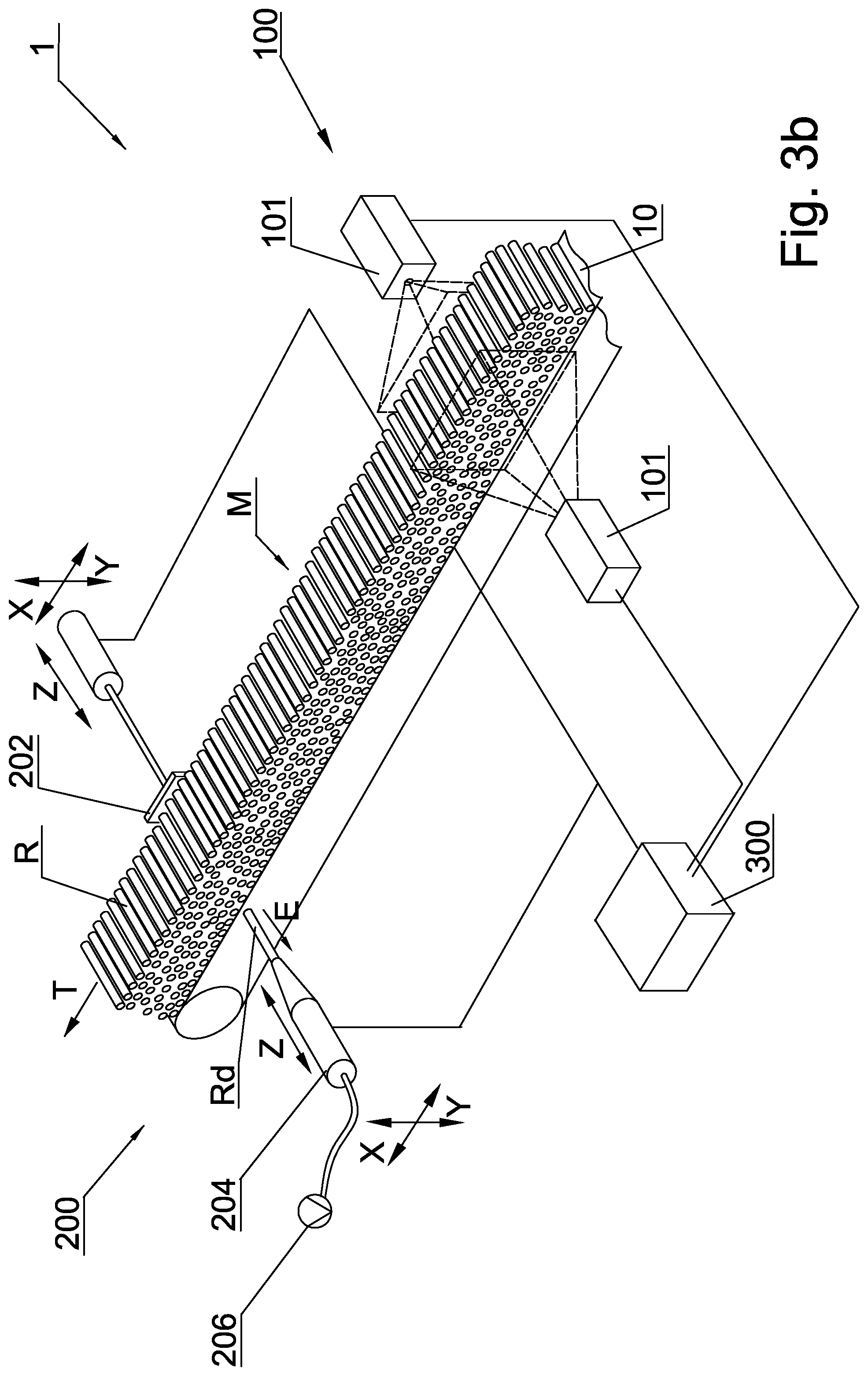
[0037] FIG. 3b shows the apparatus according to the invention in the first embodiment when the rejecting unit has moved to a position at which suction of the defective rod-like article has ended;
[0038] FIG. 3c shows the apparatus according to the invention in the first embodiment when the rejecting unit has moved to a position at which pulling out by means pliers, of the defective rod-like article has ended;
[0039] FIG. 3d shows the apparatus according to the invention in the first embodiment when the rejecting unit has moved to a position at which pulling out by means extraction needle, of the defective rod-like article has ended;
[0040] FIG. 4 shows the apparatus according to the invention in a second embodiment;
[0041] FIG. 5 shows the apparatus according to the invention in a third embodiment;
[0042] FIG. 6 shows the rejecting unit of the apparatus according to the invention in a top view;
[0043] FIG. 7 shows a method for determining the position of a defective rod-like article in the mass flow;
[0044] FIG. 8 shows a block diagram of a system according to the invention in a preferred embodiment;
[0045] FIGS. 9 and 10 show a side view of the mass flow containing defective rod-like articles, presenting various defects of the rod-like articles.
[0046] FIG. 1 shows an apparatus 1 for rejection of defective rod-like articles comprising a monitoring unit 100 and a rejecting unit 200 situated together around a mass flow of rod-like articles R. The mass flow M of rod-like articles R is effected on a conveyor 10 in the direction T.
[0047] The monitoring unit 100 comprises optical recorders 101 situated on two sides of the mass flow of rod-like articles R. The optical recorders 101 may be video cameras, photographic cameras or other devices able to record an image representing the side surfaces of the mass flow of rod-like articles R. The monitoring unit 100 has a controller which is adapted to optically determine geometrical parameters of rod-like articles R, in particular to determine the geometrical parameters of the front surface of rod-like articles R forming the mass flow M on the conveyor 10.
[0048] The rejecting unit 200 comprises a pushing element 201 and a restraining element 202. Both the pushing element 201 and the restraining element 202 are moved by means of actuators, whereas the actuator moving the pushing element 201 is adapted to make a travel being greater than the length of the rod-like articles R so that the rod-like article to be pushed out leaves the mass flow M of rod-like articles. The restraining element 202 makes movements in the axis of the rod-like articles R with a relatively small travel. The function of the restraining element 202 is to restrain the rod-like articles R situated directly around the defective rod-like article Rd to be pushed out. Due to the friction among individual articles R in the mass flow M, pushing out a defective article Rd may cause slipping out of the rod-like articles R having correct parameters. This is why the restraining element 202 has been applied.
[0049] The pushing element 201 preferably has the form of a rod having a diameter smaller than or equal to the diameter of the rod-like article R, or the form of a rod provided with a pushing tip with a corresponding diameter smaller than or equal to the diameter of the rod-like article R. The restraining element 202 preferably has the form of a plate having a hole 208 with a diameter greater than the diameter of the rod-like article R. Optionally, the restraining element 202 may have the form of a ring or a set of restraining rods which make it impossible for the rod-like articles R adjacent to a defective rod-like article Rd to slip out. In other variants of the first embodiment (FIG. 3b, 3c, 3d) the restraining element 202 may have the form of a plate without hole, or other element to restrain the defective rod-like article Rd during pulling out or suction from the mass flow M of rod-like articles.
[0050] A significant feature of the rejecting unit 200 is that it is mounted in such a way that it moves along together with the mass flow M of rod-like articles R. The rejecting unit 200 can be mounted on movable arms 209, 209' driven separately one from another, moved on rails 210, 201' in direction parallel to the direction of the of the mass flow of rod-like articles on a conveyor 10 consistent with the axis X. The first end of arms 209, 209' driven by motor 211, 211' moves on the rail 210, 210' while the other end of arms are connected by pivot. By changing spacing between arms 209, 209', the height of the pushing element 201 and the restraining element 202 are changed. In order to align the pushing element 201 with the rejecting hole 208 located in the restraining element 202, the spacing between arms 209, 209' should have the same value. In other embodiment of the rejecting unit drive the pushing element 201 and the restraining element 202 of rejecting unit 200 can be mounted on the manipulator arm. Due to the movable mounting of the rejecting unit 200, the process of pushing out defective rod-like articles Rd from the mass flow is effected without the need of dedicated stopping of the mass flow. In a situation where the mass flow stops, the rejecting unit 200 also stops and may carry out the procedure of pushing out a defective rod-like article Rd from the stopped mass flow M. Optionally, the mass flow of rod-like articles R may be stopped at the time of performance of the operation of pushing out a defective rod-like article Rd by movable the rejecting unit 200. It is possible to stopped the rejection unit 200 at the time of performance of the operation of pushing out a defective rod-like article Rd from the moving mass flow M. Preferably the movable mounting of the rejecting unit 200 is adapted in such way that at the time of performance of the operation of pushing out a defective rod-like article Rd is moving while the mass flow M with conveyor are stopped. In other embodiment mounting of the rejecting unit 200 is adapted in such way that at the time of performance of the operation of pushing out a defective rod-like article Rd, whereas mass flow M of rod-like articles R on a conveyor moves with defective rod-like articles Rd. In this embodiment the working speed of the rejecting unit 200 is high enough and the rejection time is short enough that the mass flow M remain undisturbed. Furthermore in other embodiment mounting of the rejecting unit 200 is adapted in such way that at the time of performance of rejection of the defected rod-like article Rd, is stopped together with the mass flow M.
[0051] FIG. 1 also shows a controller 300 constituting an integral part of the apparatus 1. Its function is to identify a defective rod-like article Rd basing on received data from the monitoring unit 100, and to determine its exact position in order to enable the rejecting unit 200 to push out a proper rod-like article Rd from the mass flow of rod-like articles R. The controller 300, basing on the recorded images using the criteria concerning geometrical parameters of the opposite front surfaces of rod-like articles R, identifies defective rod-like articles Rd in the mass flow M, and determines the position of defective rod-like articles Rd in the mass flow. The positioning of the recorders 101 on both sides of the mass flow M of rod-like articles R enables detecting articles whose defects occur on a single front surface. Using the recording of two images it is also possible to eliminate errors in location of defective rod-like articles caused by skewed rod-like articles R in the mass flow M.
[0052] In the embodiment shown, the image of each side of the mass flow of rod-like articles R is recorded by means of at least one camera 101. It is also possible to use two cameras on each side of the mass flow. Two cameras may be arranged at a different angle to the source of light. Such solution enables recording both reflected and scattered light. Two cameras may be also cameras of different type. The use of a colour camera allows obtaining more detailed information concerning the shape and colour of the rod-like articles, while the monochromatic cameras are considerably faster and enable more accurate tracking of changes during the flow of the rod-like articles.
[0053] FIG. 2 shows the apparatus 1 during the operation. The monitoring unit 100 has identified a defective rod-like article Rd in the mass flow M of rod-like articles R on the conveyor 10. The controller 300, basing on the data from the monitoring unit 100, has determined the position of the defective rod-like article Rd in the mass flow M and has sent control signals to the rejecting unit 200 which has moved the pushing element 201 and the restraining element 202 to a position enabling them to push out the defective rod-like article Rd from the mass flow M. In the embodiment shown, the rejecting unit 200 moves along together with the mass flow M of rod-like articles R in the direction T. The movement of the rejecting unit 200 is adjusted to the speed of the mass flow M so that during the operation of pushing out a defective rod-like article Rd the pushing element 201, the restraining element 202, and the defective rod-like article Rd do not move relative to one another in the XY-plane. The constant reciprocal position between the rejecting unit 200 and the defective rod-like article Rd in the mass flow M is maintained in the follow-up mode regardless of whether the mass flow M moves with a constant speed or whether its speed varies or the mass flow M is stopped.
[0054] Furthermore, the pushing element 201 and the restraining element 202 may independently make movements in the perpendicular direction to the front surfaces of rod-like articles R in the mass flow M. The independent movement of the restraining element 202 towards the axis Z is effected before pushing out the defective rod-like article Rd, until a position is reached in which the front surfaces of rod-like articles R situated around the defective rod-like article Rd to be rejected are pressed by the restraining element 202. Such position of the restraining element 202 is maintained relative to the rod-like articles R until the moment of pushing out the defective rod-like article Rd from the mass flow M. The independent movement of the pushing element 201 is effected when the defective rod-like article Rd is being pushed out and consists in pushing the restraining element 202 of the defective rod-like article Rd through the rejection hole 208. The function of the pushing element 201 is to push out an individual defective rod-like article Rd from the mass flow M.
[0055] FIG. 3 shows the apparatus 1 according to the invention when the rejecting unit 200 has rejected a defective rod-like article Rd. The pushing element 201 of the rejecting unit 200 has pushed out the defective rod-like article Rd in the direction Z, outside the mass flow M, whereas the restraining element 202 during pushing out of the defective rod-like article Rd restrains the rod-like articles R adjacent to the defective rod-like article Rd. Having pushed out the defective rod-like article Rd, the restraining element 202 returns to its initial position or may move to a point at which another defective rod-like article Rd to be rejected is positioned.
[0056] FIG. 3a shows the apparatus 1 according to the invention when the rejecting unit 200 has rejected a defective rod-like article Rd. In the embodiment shown the rejecting element 203 is a compressed air nozzle connected to compressed air supply of pump 206. The compressed air stream 207 of the rejecting element 203 has corresponding diameter, blowing time and power, to blow out the defective rod-like article Rd from the mass flow M, without damaging adjacent rod-like article R. The rejecting element 203 of the rejecting unit 200 has blown out the defective rod-like article Rd in the direction E, outside the mass flow M, whereas the restraining element 202 during blowing out the defective rod-like article Rd restrains the rod-like articles R adjacent to the defective rod-like article Rd. Having blown out the defective rod-like article Rd from the mass flow M, the restraining element 202 together with the rejecting element 203 returns to its initial position or may move to a point at which another defective rod-like article Rd to be rejected is positioned.
[0057] FIG. 3b shows the apparatus 1 according to the invention when the rejecting unit 200 has rejected a defective rod-like article Rd. In the embodiment shown the rejecting element 204 is a suction nozzle to sucked out the defective rod-like article Rd from the mass flow M. The diameter of suction nozzle is much bigger that the diameter of the defective rod-like article Rd. The rejecting element 204 is connected to gauge pressure supply 206, which suck out the defective rod-like article Rd in the direction E outside the mass flow M, without disturbing the mass flow M. Having sucked out the defective rod-like article Rd from the mass flow M, the restraining element 202 together with the rejecting element 204 returns to its initial position or may move to a point at which another defective rod-like article Rd to be rejected is positioned.
[0058] FIG. 3c shows the apparatus 1 according to the invention when the rejecting unit 200 has rejected a defective rod-like article Rd. In the embodiment shown the rejecting element 205 is a pulling out element in a form of pliers to pulled out the defective rod-like article Rd from the mass flow M. Having pulled out the defective rod-like article Rd from the mass flow M, the restraining element 202 together with the rejecting element 205 returns to its initial position or may move to a point at which another defective rod-like article Rd to be rejected is positioned.
[0059] The rejecting element 205 to pulling out the defected rod-like article Rd from the mass flow M, may have form of extraction needle 205' with hooked end, showed at cross-section A in FIG. 3d. The defective rod-like element Rd is pierced deep enough by the rejecting element 205', to hooked the defective rod-like article
[0060] Rd and to pulled out the defective rod-like article Rd from the mass flow M without disturbing the mass flow
[0061] M.
[0062] FIG. 4 shows a second embodiment of the apparatus 1 according to the invention wherein the rejecting unit 200 in a double configuration was used. The rejecting unit 200 according to the second embodiment is provided with a first rejecting element 201 and a second rejecting element 201', and with a first restraining element 202 and a second restraining element 202'. In this embodiment of the invention, the controller 300 by identifying the position of the defective rod-like articles Rd and Rd' controls the rejecting unit 200 so that the first rejecting element 201 rejects the first defective rod-like article Rd, and the second rejecting element 201' rejects the second defective rod-like article Rd'. The controller 300 is adapted to optimise the sequence of rejection of defective rod-like articles by minimising the time needed to remove all defective rod-like articles Rd, Rd' from the mass flow of rod-like articles R.
[0063] It is possible to apply other optimisation techniques, for example techniques taking into consideration not only the time needed to remove all the defective rod-like articles Rd, Rd', but also the degree of damage, the number of defective rod-like articles Rd, Rd', their position and distance relative to one another. Preferably the sequence of rejection of defective rod-like articles from the mass flow is determined on the basis of the smallest influence on the position of the next defective rod-like article Rd, Rd' in the mass flow M of rod-like articles R, in particular the defective rod-like articles Rd, Rd' are rejected beginning from the uppermost layer.
[0064] FIG. 5 shows another embodiment of the apparatus 1 according to the invention. In this embodiment, the rejecting unit 200 has a double configuration similar to the configuration of the embodiment shown in FIG. 4, modified in such a way that the rejection of defective rod-like articles Rd, Rd' is possible on both sides of the mass flow M. In this embodiment, the restraining element 202' is situated on the same side of the mass flow M of rod-like articles R as the pushing element 201. Similarly, the pushing element 201' is situated on the same side of the mass flow M of rod-like articles R as the restraining element 202.
[0065] Double configurations of the rejecting unit are used when the number of defective rod-like articles Rd, Rd' in the mass flow M of rod-like articles R is considerable or the speed of movement of the mass flow is high, i.e. in any situation where due to mechanical limitations the use of a single rejecting unit does not ensure a sufficient efficiency.
[0066] FIG. 6 shows the rejecting unit 200 of the apparatus 1 according to the invention in a top view. The restraining element 202 is shown in a cross-section taken at a level corresponding to the centre of the rejection hole 208.
[0067] The pushing element 201 and the restraining element 202 are positioned in one axis with the defective rod-like article Rd. The positioning in one axis is to be understood in such a way that the axis of the element 201 and the centre of the rejection hole 208 of the element 202 overlap the axis of the defective rod-like article Rd.
[0068] FIG. 7 shows a diagrammatic side view of the mass flow M of rod-like articles R with marked position of the defective rod-like article Rd. The coordinates x and y in the local coordinate system related to the monitoring unit 100 are determined based on the image 110 of the side surface of the mass flow M, comprising the view of the front surfaces of rod-like articles R among which the defective rod-like article Rd is situated. The system of local coordinates x', y' related to the rejecting unit 200 is situated at the distance L from the local coordinate system related to the monitoring unit 100. Preferably the mass flow M between the monitoring unit 100 and the rejecting unit 200 moves along with a constant speed, horizontally, therefore the information about the distance between the systems and the speed of movement of the mass flow M is sufficient to connect local coordinate systems and determine the position of the defective rod-like article Rd in the local coordinate system of the rejecting unit x', y'. However, also such positioning of the rejecting unit 200 relative to the monitoring unit 100 is possible where in order to determine the position of the defective rod-like article Rd in the local coordinate system the translation by a vector L comprising all components in all axes of the global coordinate system and the function of change of speed of the mass flow M in time and space will be required.
[0069] In the preferred embodiment, the position of a defective rod-like article Rd on the conveyor 10 may be defined by the position y and the position x in the local coordinate system, whereas the local coordinate system is preferably positioned in such a way that its axis y overlays the front surface of rod-like articles R situated on the conveyor 10 so that the position y is the distance from the longitudinal axis of the defective rod-like article Rd to the base of the mass flow M formed by the band of the conveyor 10. Since in the preferred embodiment the mass flow M of rod-like articles R is effected on the horizontal band conveyor 10, the position y does not change during the transport from the area of the monitoring unit 110 to the area of the rejecting unit 120. The position x is determined in relation to the origin of the local coordinate system being an arbitrarily selected point in the area of the monitoring unit 110. The local coordinate system related to the rejecting unit is determined in the space in a similar way. Having such a definition of local coordinate systems, the information about the distance between the origins of local coordinate systems is sufficient to determine the position of the defective rod-like article Rd. In the preferred embodiment of the apparatus 1 wherein the defective rod-like article Rd is being pushed out during the movement of the mass flow M, the distance L between the local coordinate systems changes with the movement of the rejecting unit 200.
[0070] The speed of movement of the mass flow M may be determined by means of a separate speed sensor (not shown) or based on the data coming from the images collected by the monitoring unit 100.
[0071] FIG. 8 shows a system for determining the quality of rod-like articles in the tobacco industry comprising the first apparatus 1 according to the invention for the rejection of defective rod-like articles from the mass flow of rod-like articles, and at least one intermediate apparatus 3, in particular a transport chain apparatus.
[0072] The system is further provided with the second apparatus 1' which is provided either only with the monitoring unit 100 or also with the rejecting unit 200 like the first apparatus 1. So preferably, in the system there are two apparatuses 1 according to the invention determining the quality of rod-like articles R at the beginning of the transport chain and at the end of the transport chain or transport chain fragment.
[0073] The apparatus 1' may constitute a truncated version of the apparatus 1 wherein the monitoring apparatus comprises the monitoring unit 100' and has optical recorders 101' recording the images of opposite side surfaces of the mass flow M of rod-like articles R on the conveyor, and the controller 300 which basing on the recorded images, using the criteria concerning geometrical parameters of the opposite front surfaces of the rod-like articles R, identifies defective rod-like articles Rd in the mass flow M. The second apparatus 1' may be further provided with the rejecting unit 200'.
[0074] The comparison of the number of defective rod-like articles Rd in the mass flow M at two points of the transport chain allows determining the influence of apparatuses 3 situated between the apparatuses 1 and 1' on the quality of the rod-like articles. The intermediate apparatuses 3 whose influence on the quality of the rod-like articles R may be determined include for example a loader, a tray, an unloader, a band conveyor, and a buffer store.
[0075] The system being situated between a delivery unit 2, to deliver the rod-like articles R to the system and a receiving unit 2', to receive the rod-like articles R from the system.
[0076] FIGS. 9 and 10 show an example fragment of the mass flow M of rod-like articles R in the area of the monitoring unit 110 recorded by one of the optical recorders. The shown example fragment comprises a group of rod-like articles R among which a defective rod-like article Rd is situated. FIG. 10 shows examples of defects of the rod-like articles R which may be detected in the apparatus according to the invention, these include circumferential deformations Rd, tears Rd', squashings Rd'', burrs Rd''' and the like, being visible on any of the front surfaces of the defective rod-like article R, in particular the symmetricity, the regularity of shape of the front surface of a rod-like article R, the continuity of the wrapper, the wrappings of the wrapper, and the symmetricity of insert elements visible from the front side of the article.
[0077] An advantage of the method, the apparatus and the system according to the invention is that they may be installed in existing transport systems, they do not affect the mass flow M and the process of transport of the rod-like articles R, in addition, all the rod-like articles R flowing in the mass flow M are analysed, enable detecting defects occurring on both sides or on one side regardless of the side on which such defects occurs.
* * * * *
D00000
D00001
D00002
D00003
D00004
D00005
D00006
D00007
D00008
D00009
D00010
D00011
D00012

XML
uspto.report is an independent third-party trademark research tool that is not affiliated, endorsed, or sponsored by the United States Patent and Trademark Office (USPTO) or any other governmental organization. The information provided by uspto.report is based on publicly available data at the time of writing and is intended for informational purposes only.
While we strive to provide accurate and up-to-date information, we do not guarantee the accuracy, completeness, reliability, or suitability of the information displayed on this site. The use of this site is at your own risk. Any reliance you place on such information is therefore strictly at your own risk.
All official trademark data, including owner information, should be verified by visiting the official USPTO website at www.uspto.gov. This site is not intended to replace professional legal advice and should not be used as a substitute for consulting with a legal professional who is knowledgeable about trademark law.