Systems and Methods Implementing Air Conditioning Systems
Diamond; Anthony ; et al.
U.S. patent application number 16/509373 was filed with the patent office on 2020-01-16 for systems and methods implementing air conditioning systems. This patent application is currently assigned to Axiom Exergy Inc.. The applicant listed for this patent is Axiom Exergy Inc.. Invention is credited to Anthony Diamond, Marc Khalaf, John Lerch, Karthik Nithyanandam, Amrit Robbins, Nikhil Saralkar.
| Application Number | 20200018503 16/509373 |
| Document ID | / |
| Family ID | 69139049 |
| Filed Date | 2020-01-16 |


View All Diagrams
| United States Patent Application | 20200018503 |
| Kind Code | A1 |
| Diamond; Anthony ; et al. | January 16, 2020 |
Systems and Methods Implementing Air Conditioning Systems
Abstract
Systems and methods for implementing air conditioning and water store systems that are configured such that a direct expansion of a heat transfer material allows for both hot and cold thermal storage are provided. In such systems, an included cold thermal energy storage unit can be cooled to a temperature lower than the temperature desired for a target space while the target space is simultaneously cooled to the desired temperature, such that the temperature desired for the target space can subsequently be established and/or maintained by the cold thermal energy storage unit irrespective of whether the cold thermal energy storage unit is being principally relied on to cool the target space or whether an included powered condensing unit is being relied on to cool the target space. In conjunction with this, hot thermal units and water in a water store can be heated. In short, the system allows for the capture of normally ejected heat in the water store.
| Inventors: | Diamond; Anthony; (Richmond, CA) ; Nithyanandam; Karthik; (Richmond, CA) ; Khalaf; Marc; (Richmond, CA) ; Lerch; John; (Richmond, CA) ; Saralkar; Nikhil; (Richmond, CA) ; Robbins; Amrit; (Richmond, CA) | ||||||||||
| Applicant: |
|
||||||||||
|---|---|---|---|---|---|---|---|---|---|---|---|
| Assignee: | Axiom Exergy Inc. Richmond CA |
||||||||||
| Family ID: | 69139049 | ||||||||||
| Appl. No.: | 16/509373 | ||||||||||
| Filed: | July 11, 2019 |
Related U.S. Patent Documents
| Application Number | Filing Date | Patent Number | ||
|---|---|---|---|---|
| 62696712 | Jul 11, 2018 | |||
| Current U.S. Class: | 1/1 |
| Current CPC Class: | F24D 3/02 20130101; F24F 11/30 20180101; F24F 11/83 20180101; F24F 11/86 20180101; F24D 2200/08 20130101; F24F 11/875 20180101; F24F 2005/0025 20130101; F24D 19/1009 20130101; F24D 3/10 20130101 |
| International Class: | F24F 11/30 20060101 F24F011/30; F24F 11/86 20060101 F24F011/86; F24F 11/875 20060101 F24F011/875; F24F 11/83 20060101 F24F011/83; F24D 3/02 20060101 F24D003/02; F24D 3/10 20060101 F24D003/10; F24D 19/10 20060101 F24D019/10 |
Claims
1. An air conditioning system comprising: a condensing unit; a liquid pressurizer and distributor ensemble; a cold thermal energy storage unit connected to the liquid pressurizer and distributor ensemble by at least one liquid connection; a target space; a suction gas pressurizer and distributor ensemble; a discharge gas distributor; and a hot water storage unit having a storage tank, a volume of water disposed therein; and a thermal energy transfer unit operatively connected to piping containing a supplied working fluid such that the supplied working fluid may be exposed to the thermal energy within the hot water storage unit by way of the thermal energy transfer unit, and wherein: the condensing unit, the liquid pressurizer and distributor ensemble, the cold thermal energy storage unit, the target space, the suction gas pressurizer and distributer ensemble, the discharge gas distributor, and the hot water storage unit are operatively connected by piping such that vapor compression cycles can be simultaneously implemented that result in the air conditioning of the target space and a thermal energy transfer in the cold thermal energy storage unit and/or the hot water storage unit.
2. The air conditioning system of claim 1, wherein the suction gas pressurizer and distributor ensemble comprises: at least one of: a pressure regulator and a compressor; and a flow control apparatus operable to controllably direct vapor phase working fluid to adjoined structures.
3. The air conditioning system of claim 1, wherein the cold thermal energy storage unit comprises a phase change material encased in thermal insulation.
4. The air conditioning system of claim 1, wherein the liquid pressurizer and distributor ensemble comprises a pump that is operable to alter the pressure of received liquid phase working fluid, and a flow control apparatus operable to controllably direct received liquid phase working fluid to adjoined structures.
5. The air conditioning system of claim 1, wherein the condensing unit is operable to output heated vapor phase working fluid.
6. The air conditioning system of claim 5, wherein the condensing unit comprises an integrated heating source and is thereby operable to output heated vapor phase working fluid.
7. The air conditioning system of claim 1, further comprising a second liquid connection between the cold thermal energy storage unit and the liquid pressurizer and distributor ensemble.
8. The air conditioning system of claim 7, wherein the cold thermal storage unit is operable to subcool the supplied working fluid as it is removed from the hot water storage unit thereby capturing and storing an excess of heat from the supplied working fluid.
9. The air conditioning system of claim 7 wherein the cold thermal storage unit is operable to receive a liquid phase working fluid from the condensing unit through the liquid pressurizer distributor ensemble such that the liquid phase working fluid is subcooled and distributed to the target space thereby performing a cooling of the target space while simultaneously the working fluid leaves the target space as a gas phase and is redistributed to the condensing unit by way of the suction gas pressurizer distributor ensemble.
10. The air conditioning system of claim 1, wherein the discharge gas distributor circulates the supplied heated vapor phase working fluid to the target space thereby providing heating services to the target space.
11. The air conditioning system of claim 10, wherein the condensing unit is configured to output heated vapor phase working fluid such that when the heated vapor phase working fluid is directed by piping to the target space and/or the hot water storage unit, it condenses into a liquid phase working fluid.
12. The air conditioning system of claim 1, further comprising a second liquid connection between the liquid pressurizer and distributor ensemble and the condensing unit.
13. The air conditioning system of claim 1, wherein the hot water storage unit further comprises an immersion heater connected to the hot water storage unit and operable to heat the water disposed therein.
14. The air conditioning system of claim 1 wherein the thermal energy transfer unit is a heat exchanger coil disposed within the storage tank.
15. The air conditioning system of claim 1, wherein the hot water storage unit is operable to act as a heat source; wherein: the hot water storage unit and the target space are operatively connected by piping; and the hot water storage unit is configured to receive liquid phase working fluid, and heat it so that it outputs vapor phase working fluid that thereafter be directed to the target space to heat it.
16. The air conditioning system of claim 15, wherein the air conditioning system is configured such that the vapor phase working fluid that is output by the hot water storage unit and thereafter directed to the target space, transmits heat to the target space and thereby condenses.
17. The air conditioning system of claim 1, further comprising a hot thermal energy storage unit operatively connected to the liquid pressurizer distributor ensemble and the discharge gas distributor ensemble by piping.
18. The air conditioning system of claim 17, wherein the hot thermal energy storage unit further comprises a thermal storage medium encased with an insulating material.
19. The air conditioning system of claim 1, wherein the condensing unit comprises a compressor and a condenser/evaporator in series, and wherein the condensing unit is operable to direct a received liquid phase working fluid through an expansion valve to the condenser/evaporator to output a vapor phase working fluid and direct the vapor phase working fluid into a compressor to compress the vapor phase working fluid such that the compressor can output a high temperature high pressure discharge gas.
20. The air conditioning system of claim 19, wherein the condensing unit further comprises a liquid suction line heat exchanger operatively connected to the compressor and the condenser/evaporator by piping.
21. The air conditioning system of claim 20, wherein the suction line heat exchanger is operative to simultaneously transfer heat between a liquid line and a suction line.
22. The air conditioning system of claim 17, further comprising more than one gas discharge connection.
23. The air conditioning system of claim 1, wherein the system is configured such that when the vapor compression cycles are simultaneously implemented that result in the air conditioning of the target space and a thermal energy transfer in the cold thermal storage unit and hot water storage unit, the cold thermal energy storage unit expands and evaporates the supplied working fluid and receives cooling services while the hot water storage unit simultaneously condenses the supplied heated vapor phase working fluid and receives heating services.
24. An air conditioning system comprising: a condensing unit; a liquid pressurizer and distributor ensemble; a cold thermal energy storage unit connected to the liquid pressurizer and distributor ensemble by at least two liquid connections; a target space; and a suction gas pressurizer and distributor ensemble; wherein: the condensing unit, the liquid pressurizer and distributor ensemble, the cold thermal energy storage unit, the target space, and the suction gas pressurizer and distributer ensemble are operatively connected by piping such that vapor compression cycles can be simultaneously implemented that result in the air conditioning of the target space and a thermal energy transfer in the cold thermal energy storage unit; and the air conditioning system is configured such that when the vapor compression cycles are simultaneously implemented that result in the air conditioning of the target space and a thermal energy transfer in the cold energy storage unit, the target space receives heating services by a supplied vapor phase working fluid from the condensing unit and supplies a portion of a condensed liquid phase working fluid to the cold thermal energy storage unit whereby the cold thermal energy storage unit subcools the condensed liquid phase working fluid by capturing and storing excess heat from the condensed liquid phase working fluid.
25. An air conditioning system comprising: a condensing unit; a liquid pressurizer and distributor ensemble; a cold thermal energy storage unit connected to the liquid pressurizer and distributor ensemble by at least one liquid connection; a first and second target space; a suction gas pressurizer and distributor ensemble; and a discharge gas distributor; wherein: the condensing unit, the liquid pressurizer and distributor ensemble, the cold thermal energy storage unit, the first and second target spaces, the suction gas pressurizer and distributer ensemble, and the discharge gas distributor are operatively connected by piping such that vapor compression cycles can be simultaneously implemented that result in the air conditioning of the target space and a thermal energy transfer in the cold thermal energy storage unit; and the air conditioning system is configured such that the suction gas pressurizer and distributor ensemble enables the cooling of the first and second target spaces to different temperatures.
26. The air conditioning system of claim 25, further comprising at least one hot thermal energy storage unit, wherein the condensing unit, the liquid pressurizer and distributor ensemble, the cold thermal energy storage unit, the first and second target spaces, the suction gas pressurizer and distributer ensemble, the discharge gas distributor, and the hot thermal energy storage unit are operatively connected by piping such that vapor compression cycles can be simultaneously implemented that result in the air conditioning of the target space and a thermal energy transfer in the hot or cold thermal energy storage unit.
Description
CROSS REFERENCED APPLICATIONS
[0001] This application claims priority to U.S. Provisional Patent Application No. 62/696,712 filed on Jul. 11, 2018. The enclosure of which is included herein by reference in its entirety
FIELD OF THE INVENTION
[0002] The present invention generally relates to air conditioning and water heating systems that implement thermal energy storage devices.
BACKGROUND
[0003] Air conditioning is a convenience that is ubiquitous in modern society. Within the context of the instant application, `air conditioning` can be understood to refer to the controlling of the properties of air--especially temperature--within a defined space, and is inclusive of both the heating and cooling of air (although note that `air conditioning` is sometimes colloquially interpreted not to refer to heating--i.e. heating is sometimes colloquially understood to be separate from air conditioning). Air conditioning can be implemented using any of a variety of devices, and is typically used, for instance, to help create comfortable indoor environments. Importantly, one critical application for air conditioning is refrigeration, which is generally used to preserve/elongate the shelf life of foods. Typical air conditioning systems--including refrigerators--employ a `vapor-compression` cycle to cool a targeted space. In a `vapor-compression` cycle, a working fluid (e.g. a refrigerant) is circulated proximate the targeted space that is to be cooled, and is made to undergo iterative phase changes to continually remove heat from the targeted space and eject it outside of the targeted space.
[0004] Vapor-compression cycles are typically implemented via a compressor, an expansion valve, an evaporator, and a condenser, all operatively connected via piping that facilitates the circulation of a working fluid. Typically, the working fluid--in its liquid phase--is made to pass through the expansion valve and thereby experiences a pressure drop, and a corresponding temperature drop. The working fluid--typically then in a saturated fluid phase--subsequently passes through the evaporator, which is the target of the cooling efforts. This saturated fluid absorbs heat from the evaporator, and consequently is made to substantially evaporate into a vapor phase. The substantially vapor phase working fluid then passes through a compressor where it is compressed to a higher pressure, and relatedly a higher temperature. Thereafter, the high pressure, high temperature vapor phase working fluid passes through a condenser, where it releases heat outside of the evaporator and thereby condenses into a liquid phase working fluid, which can be re-circulated. Accordingly, it is enumerated how vapor-compression cycles are generally implemented to remove heat from a targeted space.
SUMMARY OF THE INVENTION
[0005] Systems and methods in accordance with embodiments of the invention implement air conditioning systems that are operable to establish/maintain a desired temperature for a target space and simultaneously establish/maintain a desired temperature for an included hot/cold thermal energy storage unit, such that the hot/cold thermal energy storage unit can subsequently be used to establish/maintain a desired temperature for the target space without having to principally rely on the operation of a powered condensing unit. In one embodiment, an air conditioning system includes: a condensing unit, a liquid pressurizer and distributor ensemble, a cold thermal energy storage unit connected to the liquid pressurizer and distributor ensemble by at least one liquid connection, a target space, a suction gas pressurizer and distributor ensemble, a discharge gas distributor, and a hot water storage unit. The hot water storage unit has a storage tank that holds a volume of water. Additionally, the hot water storage unit has a thermal energy transfer unit that is operatively connected to piping containing a supplied working fluid such that the supplied working fluid may be exposed to the thermal energy within the hot water storage unit by way of the thermal energy transfer unit. The condensing unit, the liquid pressurizer and distributor ensemble, the cold thermal energy storage unit, the target space, the suction gas pressurizer and distributer ensemble, the discharge gas distributor, and the hot water storage unit are operatively connected by piping such that vapor compression cycles can be simultaneously implemented that result in the air conditioning of the target space and a thermal energy transfer in the cold thermal energy storage unit and/or the hot water energy storage unit.
[0006] In still other embodiments, the suction gas pressurizer and distributor ensemble has a pressure regulator or a compressor, and a flow control apparatus operable to controllably direct vapor phase working fluid to adjoined structures.
[0007] In yet other embodiments, the cold thermal energy storage unit comprises a phase change material encased in thermal insulation.
[0008] In still yet other embodiments, the liquid pressurizer and distributor ensemble has a pump that is operable to alter the pressure of received liquid phase working fluid, and a flow control apparatus operable to controllably direct received liquid phase working fluid to adjoined structures.
[0009] In other embodiments, the condensing unit is operable to output heated vapor phase working fluid.
[0010] In still other embodiments, the condensing unit comprises an integrated heating source and is thereby operable to output heated vapor phase working fluid.
[0011] In yet other embodiments, the air conditioning system further comprising a second liquid connection between the cold thermal energy storage unit and the liquid pressurizer and distributor ensemble.
[0012] In other embodiments, the cold thermal storage unit is operable to subcool the supplied working fluid as it is removed from the hot water storage unit thereby capturing and storing an excess of heat from the supplied working fluid.
[0013] In still yet other embodiments, the cold thermal energy storage unit is operable to receive a liquid phase working fluid from the condensing unit through the liquid pressurizer distributor ensemble such that the liquid phase working fluid is subcooled and distributed to the target space thereby performing a cooling of the target space while simultaneously the working fluid leaves the target space as a gas phase and is redistributed to the condensing unit by way of the suction gas pressurizer distributor ensemble.
[0014] In other embodiments, the discharge gas distributor circulates the supplied heated vapor phase working fluid to the target space thereby providing heating services to the target space.
[0015] In still other embodiments, the condensing unit is configured to output heated vapor phase working fluid such that when the heated vapor phase working fluid is directed by piping to the target space and/or the hot water storage unit, it condenses into a liquid phase working fluid.
[0016] In yet other embodiments, the air conditioning system has a second liquid connection between the liquid pressurizer and distributor ensemble and the condensing unit.
[0017] In still yet other embodiments, the water storage unit further comprises an immersion heater connected to the water storage unit and operable to heat the water disposed therein.
[0018] In other embodiments, the thermal energy transfer unit is a heat exchanger coil disposed within the storage tank.
[0019] In still other embodiments, the hot water storage unit is operable to act as a heat source; wherein: the hot water storage unit and the target space are operatively connected by piping; and the hot water storage unit is configured to receive liquid phase working fluid, and heat it so that it outputs vapor phase working fluid that thereafter can be directed to the target space to provide heating services.
[0020] In yet other embodiments, the air conditioning system is configured such that the vapor phase working fluid that is output by the hot water storage unit and thereafter directed to the target space, transmits heat to the target space and thereby condenses.
[0021] In still yet other embodiments, the air conditioning system has a hot thermal energy storage unit operatively connected to the liquid pressurizer distributor ensemble and the discharge gas distributor ensemble by piping.
[0022] In other embodiments, the hot thermal energy storage unit has a thermal storage medium encased with an insulating material.
[0023] In still other embodiments, the condensing unit has a compressor and a condenser/evaporator in series, and the condensing unit is operable to direct a received liquid phase working fluid through an expansion valve to the condenser/evaporator to output a vapor phase working fluid and direct the vapor phase working fluid into a compressor to compress the vapor phase working fluid such that the compressor can output a high temperature high pressure discharge gas.
[0024] In yet other embodiments, the condensing unit has a liquid suction line heat exchanger operatively connected to the compressor and the condenser/evaporator by piping.
[0025] In still yet other embodiments, the suction line heat exchanger is operative to simultaneously transfer heat between a liquid line and a suction line.
[0026] In other embodiments, the air conditioning system has more than one gas discharge connection.
[0027] In still other embodiments, the system is configured such that when the vapor compression cycles are simultaneously implemented that result in the air conditioning of the target space and a thermal energy transfer in the cold thermal storage unit and hot water storage unit, the cold thermal energy storage unit expands and evaporates the supplied working fluid and receives cooling services while the hot water storage unit simultaneously condenses the supplied heated vapor phase working fluid and receives heating services.
[0028] Other embodiments of an air conditioning system include a condensing unit, a liquid pressurizer and distributor ensemble, a cold thermal energy storage unit connected to the liquid pressurizer and distributor ensemble by at least two liquid connections, a target space, and a suction gas pressurizer and distributor ensemble. The condensing unit, the liquid pressurizer and distributor ensemble, the cold thermal energy storage unit, the target space, and the suction gas pressurizer and distributer ensemble are operatively connected by piping such that vapor compression cycles can be simultaneously implemented that result in the air conditioning of the target space and a thermal energy transfer in the cold thermal energy storage unit. Additionally, the air conditioning system is configured such that when the vapor compression cycles are simultaneously implemented that result in the air conditioning of the target space and a thermal energy transfer in the cold energy storage unit, the target space receives heating services by a supplied vapor phase working fluid from the condensing unit and supplies a portion of a condensed liquid phase working fluid to the cold thermal energy storage whereby the cold thermal energy storage subcools the condensed liquid phase working fluid by capturing and storing excess heat from the condensed liquid phase working fluid.
[0029] Other embodiments of an air conditioning system also include a condensing unit, a liquid pressurizer and distributor ensemble, a cold thermal energy storage unit connected to the liquid pressurizer and distributor ensemble by at least one liquid connection, a first and second target space, a suction gas pressurizer and distributor ensemble, and a discharge gas distributor. The condensing unit, the liquid pressurizer and distributor ensemble, the cold thermal energy storage unit, the first and second target spaces, the suction gas pressurizer and distributer ensemble, and the discharge gas distributor are operatively connected by piping such that vapor compression cycles can be simultaneously implemented that result in the air conditioning of the target space and a thermal energy transfer in the cold thermal energy storage unit. Additionally, the air conditioning system is configured such that the suction gas pressurizer and distributor ensemble enables the cooling of the first and second target spaces to different temperatures.
[0030] In still other embodiments, the air conditioning system has a first hot thermal storage unit, the condensing unit, the liquid pressurizer and distributor ensemble, the cold thermal energy storage unit, the first and second target spaces, the suction gas pressurizer and distributer ensemble, the discharge gas distributor, and the hot thermal energy storage unit are operatively connected by piping such that vapor compression cycles can be simultaneously implemented that result in the air conditioning of the target space and a thermal energy transfer in the hot or cold thermal energy storage unit.
[0031] Additional embodiments and features are set forth in part in the description that follows, and in part will become apparent to those skilled in the art upon examination of the specification or may be learned by the practice of the disclosed subject matter. A further understanding of the nature and advantages of the present disclosure may be realized by reference to the remaining portions of the specification and the drawings, which forms a part of this disclosure.
BRIEF DESCRIPTION OF THE DRAWINGS
[0032] These and other features and advantages of the present apparatus and methods will be better understood by reference to the following detailed description when considered in conjunction with the accompanying data and figures, which are presented as exemplary embodiments of the disclosure and should not be construed as a complete recitation of the scope of the inventive method, wherein:
[0033] FIGS. 1A-1K illustrate air conditioning and water store system having a heat thermal store having a single discharge gas connection, and plots showing exemplary operation, in accordance with certain embodiments of the invention.
[0034] FIGS. 2A-2E illustrate air conditioning and water store systems having a heat thermal store having multiple discharge gas connections, and data plots showing exemplary operation, in accordance with certain embodiments of the invention.
[0035] FIGS. 3A-3C illustrate an air conditioning system without a water store in accordance with certain embodiments of the invention.
[0036] FIGS. 4A-4J illustrate an air conditioning system with a cold thermal store and plots illustrating exemplary operational modes, in accordance with embodiments of the invention.
[0037] FIGS. 5A-5D illustrate an air conditioning system with a cold thermal store and a water store in accordance with embodiments of the invention.
[0038] FIGS. 6A-6I illustrate embodiments and operational modes of a condensing unit in accordance with embodiments of the invention.
[0039] FIGS. 7A and 7B illustrate embodiments of water stores incorporating heat exchangers in accordance with embodiments of the invention
[0040] FIGS. 8A-8D illustrate embodiments of a cold thermal store in accordance with embodiments of the invention.
[0041] FIGS. 9A and 9B illustrate ejector configurations for air conditioning systems and water stores in accordance with certain embodiments of the invention.
[0042] FIGS. 9C-9E provide data plots showing exemplary operation of ejector systems in accordance with certain embodiments of the invention.
[0043] FIGS. 10A and 10B illustrate embodiments and operational modes of an air conditioning system incorporating an ejector in accordance with certain embodiments of the invention.
DETAILED DESCRIPTION
[0044] Turning now to the drawings, systems and methods for implementing air conditioning and water store systems that are configured such that a direct expansion of a heat transfer material allows for both hot and cold thermal storage. In embodiments of such systems, an included cold thermal energy storage unit can be cooled to a temperature lower than the temperature desired for a target space while the target space is simultaneously cooled to the desired temperature, such that the temperature desired for the target space can subsequently be established and/or maintained by the cold thermal energy storage unit irrespective of whether the cold thermal energy storage unit is being principally relied on to cool the target space or whether an included powered condensing unit is being relied on to cool the target space. In conjunction with this, hot thermal units and water in a water store can be heated. In short, the system allows for the capture of normally ejected heat in the water store.
[0045] In a number of embodiments, an air conditioning system is configured to heat/cool the included hot/cold thermal energy storage unit to a temperature desired for the target space such that--when the hot/cold thermal energy storage unit is principally relied on to establish/maintain the desired temperature for the target space--the associated working fluid can be iteratively circulated through the target space and the hot/cold thermal energy storage units such that: (1) as the working fluid passes through the target space it substantially evaporates and absorbs or distributes heat within the target space so that the desired temperature for the target space can be established/maintained, and (2) when the substantially evaporated working fluid passes through the hot/cold thermal energy storage units, the temperature of the hot/cold thermal energy storage unit is low enough to cause the condensation of the substantially vapor phase working fluid, e.g. so that it can be reintroduced to the target space and continue to redistribute heat. In this way, the target space can be held at a precise desired temperature irrespective of whether the air conditioning system is principally relying on the hot/cold thermal energy storage unit to provide cooling or whether the air conditioning system is relying on a powered condensing unit (e.g. continually powered by a connection to a power grid) or heat pump to provide heating/cooling.
[0046] As can be appreciated, the removal or addition of heat from or to a targeted space (e.g. as happens in air conditioning systems) and the need to heat water for household purposes can be a substantially energy intensive operation. Moreover, given the reliance by modern society on the creation of comfortable living environments and water of a desirable temperature, it can further be appreciated how such systems can impose a substantial burden on power generation facilities. To mitigate these potential burdens on power infrastructure, many electricity providers impose a time-of-use (TOU) pricing schedule--e.g. charging more for providing electricity during the day where the demand for electricity/cooling is typically greater--so as to address load balancing/intermittency problems on the grid. Consequently, to take advantage of the tiered pricing, many electricity consumers have focused on developing/implementing energy storage technologies enabling them to purchase energy at a lower rate (e.g. during middle of the night), and store it for use during the day (when the cost of electricity is higher). As can be appreciated, this energy storage behind-the-meter can provide a substantial economic benefit for such TOU customers. Note that this economic benefit is accentuated when the consumer has a very small load factor defined as the average load divided by maximum load in a given time period.
[0047] Thermal energy storage (TES) refers to accruing thermal energy, and storing it for later use, and is often implemented in the context of air conditioning systems. For example, in some instances, flake and slushy ice is regularly generated to maintain the temperature of products during transport or display; such methods surround the products such as poultry and fish directly with a phase change material (PCM) such as ice or brine. In U.S. Pat. No. 4,280,335, a method for utilizing an ice bank PCM to provide cooling load for cooled display cases and the `heating ventilating, and air conditioning` ("HVAC") system of a supermarket is enumerated. In this method, coolant in the form of liquid water is produced from the ice bank and is pumped to display cases and the HVAC system to offset energy consumption. The disclosure of U.S. Pat. No. 4,280,335 is incorporated by reference herein. Other notable prior art includes U.S. Pat. No. 5,383,339, which presents an apparatus that couples to an existing refrigeration system to cool a PCM. This PCM TES is then utilized to offset electricity demand by subcooling the liquid refrigerant of a second auxiliary refrigeration circuit in order to increase its cooling capacity and improve the refrigeration system's efficiency during discharge mode. The disclosure of U.S. Pat. No. 5,383,339 is incorporated by reference herein.
[0048] Although previous methods for storing thermal energy within the context of air conditioning systems have been effective to some extent, the current state of the art can benefit from more robust and effective methods for storing and using stored thermal energy. For example, many prior art air conditioning systems that rely on the implementation of a vapor-compression cycle and incorporate thermal energy storage mechanisms are not configured such that the associated thermal energy storage unit can be principally relied on to provide cooling to the same extent as when the air conditioning system utilizes a powered condenser/compressor (e.g. powered by the grid). Rather, many such systems utilize an included thermal energy storage unit as a supplemental mechanism to facilitate cooling; e.g. in many such systems, separate compressor and condenser units are still relied on to effectuate the vapor-compression cycle. Alternatively, in a number of such systems, the included thermal energy storage unit can be principally relied on to provide for cooling, but not to the same extent as when the air conditioning system utilizes condenser/compressor units. Although not as robust, such systems may find use where precise cooling temperatures are not required--e.g. the cooling of a living quarters. By contrast, such systems may not be sufficient in situations such as refrigeration, where precise cooling temperatures are desired.
[0049] Against this backdrop, many embodiments of the invention implement air conditioning systems whereby a hot/cold thermal energy storage units and potentially a hot water storage system are included within an air conditioning circuit, where the air conditioning system is configured such that a desired temperature for a target space can be maintained irrespective of whether the hot/cold thermal energy storage unit is being principally relied on to heat/cool the target space or whether the air conditioning system is relying on a separately powered condensing unit (e.g. including a compressor unit and a condenser unit) to help heat/cool the target space, and where heat energy created during the process can be used for a secondary purpose, such as, for example heating water. For example, in a number of embodiments, an air conditioning system incorporates a hot/cold thermal energy storage devices that are configured to be heated/cooled to a temperature lower than that desired for a targeted space. For instance, the air conditioning system can utilize an incorporated powered condensing unit to heat/cool the hot/cold thermal energy storage unit to a temperature higher/lower than that desired for a targeted space; note that the air conditioning system can be configured such that it can simultaneously utilize the powered condensing unit to establish/maintain the desired temperature for the targeted space. The air conditioning system can further be configured such that the thermal energy stored in the hot/cold thermal energy storage units (which was heated/cooled to a temperature higher/lower than that desired for the target space) can thereafter be principally relied on (e.g. substantially without the assistance of a powered condensing unit) to establish/maintain the desired temperature for the targeted space for at least some period of time. In many embodiments, the air conditioning system is configured such that the hot/cold thermal energy storage units can be heated/cooled to a temperature higher/lower than that desired for the target space such that--when the hot/cold thermal energy storage unit is principally relied on to heat/cool the target space--the associated working fluid is iteratively circulated through the target space and the hot/cold thermal energy storage unit such that: (1) as the working fluid passes through the target space it redistributes heat within the target space so that the desired temperature for the target space can be established/maintained, and (2) when the working fluid passes through the hot/cold thermal energy storage unit, the temperature of the hot/cold thermal energy storage unit is sufficient to cause a change in the vapor phase of the working fluid, e.g. so that it can be reintroduced to the target space to continue to redistribute heat.
[0050] In a number of embodiments, these configurations can allow for any included compressors or condensers to be deactivated when the thermal energy storage unit is being principally relied on to provide heating/cooling; in other words, the target space can be heated/cooled to the desired temperature even in the absence of the operation of condensers and compressors. As can be appreciated, the operation of the compressors and condensers is the principal source of energy consumption for many air conditioning systems. Accordingly, many embodiments utilize various configurations of components and operational modes to reduce the energy consumption from the condensers and compressors that may be used. Likewise the use of hot/cold thermal energy stores can reduce the component redundancy that can arise one or more system may be needed for the same space. Furthermore, the systems may also be able to scavenge and store heat from space heating and/or hot water generation services in the hot/cold thermal store to be used to heat a water store and/or provide space heating when it is inefficient to run a heat pump (such as when the environmental temperature is very low).
[0051] In general, such air conditioning systems can provide for substantial energy efficiency and financial savings. Moreover, such systems can further be utilized for their inherent ability to provide effective backup services, e.g. in the case of a power disruption. Configurations for air conditioning systems, along with their respective operation, in accordance with many embodiments of the invention are now discussed below.
Configurations for, and the Operation of Air Conditioning Systems Incorporating Hot and Cold Thermal Energy Storage Devices
[0052] In many embodiments, air conditioning systems incorporate both hot and cold thermal energy storage units within a refrigerant circuit such that a desired temperature for a target space can be established/maintained irrespective of whether an included condensing unit is being relied on or whether an included cold thermal energy storage unit is being relied on--e.g. without the assistance of the powered condensing unit. In numerous embodiments, air conditioning systems are configured to be operable to establish and/or maintain a temperature for the included cold thermal energy storage unit that is lower than the temperature desired for the target space, while simultaneously cooling the target space to the desired temperature. In this way, the thermal energy storage unit can thereafter be principally relied on--e.g. without the assistance of a powered condensing unit--to cool the target space to the same extent that the included, powered, condensing unit can. Note that, as can be appreciated, the air conditioning system may still require power for operation of ancillary components.
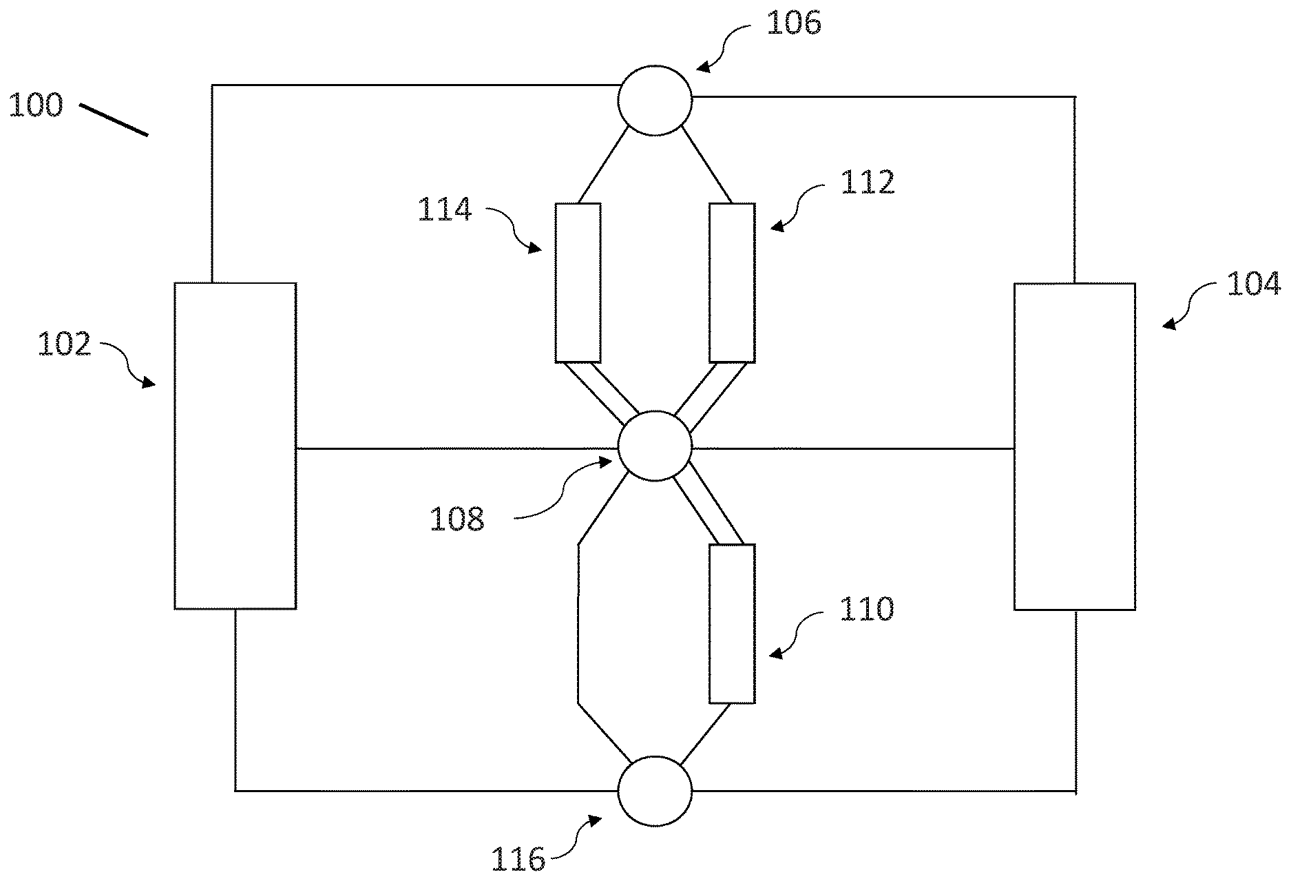
[0053] In many embodiments, air conditioning systems are configured with a hot thermal store with one discharge connection, a cold thermal store with one suction connection, and a bypass connection between the liquid pressurizer/distributor ensemble and the suction gas pressurizer/distributor ensemble, as illustrated in FIGS. 1A-1k. Note that throughout all of the figures depicted in the instant application, valves may not be explicitly depicted. However, as can be appreciated, valves can be implemented any of the depicted figures to facilitate the desired flow. In any case, FIG. 1A illustrates a configuration and components of an embodiment of an air conditioning system 100 while not in operation; more specifically, FIG. 1A illustrates an embodiment of an air conditioning system 100 that includes a condensing unit 102, a target space 104, a discharge gas distributor ensemble 106, a liquid pressurizer and distributor ensemble 108, a cold thermal energy storage unit 110, a hot thermal store 112, a water store 114, and a suction gas pressurizer and distributor ensemble 116, all of which are operatively interconnected by piping such that a vapor-compression cycle can be implemented to heat or cool the target space 104 using either the condensing unit 102 or the cold or hot thermal energy storage units (110/112), and further configured such that a working fluid can be circulated through the cold or hot energy storage units (110/112), water store 114, and the target space 104 to transport heat as desired. Importantly, within the context of this application, the suction gas pressurizer and distributor ensemble 116 is sometimes referred to as the `suction gas/equalizer ensemble` or `suction gas/equalizer,` or `suction gas equalizer/distributor ensemble`, or `suction gas equalizer/distributor,` or the like. Additionally, within the context of this application, the hot or cold thermal energy storage units may be referred to as hot or cold energy store, hot or cold thermal store, hot or cold thermal energy store, or the like. Furthermore, as can be appreciated within the context of the application, references to e.g. low temperature/pressure and high temperature/pressure are relative, and can be understood to be interpreted within the context of a vapor compression cycle.
[0054] The condensing unit 102 is generally operable to pressurize and/or condense received low pressure, low temperature vapor phase working fluid (e.g. exiting from the target space 104 and/or the thermal energy storage unit (112/110)) such that it changes phase to a high temperature, high pressure liquid, e.g. within the context of a vapor-compression cycle. In addition, the condensing unit 102 is also generally operable to expand, evaporate and/or pressurize received high pressure liquid phase working fluid (e.g. exiting from the target space 104 and/or the thermal energy storage unit (112/110) such that it changes phase to a high temperature, high pressure vapor, e.g. within the context of a vapor-compression cycle. Although the condensing unit 102 is depicted schematically, it should be appreciated that it can be implemented using any of variety of schemes. For example, in many embodiments, the condensing unit 102 comprises a compressor--to compress received vapor phase working fluid--and a heat exchanger and expansion valve to act as condenser to condense the high pressure vapor phase working fluid to a liquid phase working fluid or act as an evaporator to expand and evaporate high pressure liquid phase working fluid to a vapor phase working fluid. Of course, to be clear, a condensing unit can be effectuated in any of a variety of ways in accordance with embodiments of the invention. Examples of some of the condensing units that can be implemented in the depicted figures are discussed in subsequent sections below.
[0055] The discharge gas distributor ensemble 106 and liquid pressurizer and distributor ensemble 108 generally operate to regulate pressure and/or circulate working fluid as desired to facilitate the operation of the air conditioning system in accordance with any of its various operating modes. For example, the liquid pressurizer and distributor ensemble 108 can circulate working fluid through the thermal energy storage units (110/112), through the target space 104, or simultaneously through each of the hot/cold thermal energy storage unit (110/112) and the target space 104. In general, the liquid pressurizer and distributor ensemble 108 functions to accept liquid phase flow from any connected components, alter the flow pressure as necessary (if appropriate), and/or distribute the received flow to an appropriate connected component in accordance with any of the air conditioning system's operating modes. Additionally, note that the liquid pressurizer and distributor ensemble 108 can be implemented using any of a variety of components. For example, any suitable pump can be used to pressurize received liquid phase working fluid, and any suitable control apparatus can be implemented to redirect the working fluid as desired. To be clear, embodiments of the invention are not limited to the implementation of particular configurations for liquid pressurizer and distributor ensembles. Examples of some of the liquid pressurizer and distributor ensembles that can be incorporated are discussed in subsequent sections below. Importantly, within the context of the instant application, the term `liquid pressurizer and distributor ensemble` can reference even those devices that are only operable to controllably distribute liquid phase working fluid. Additionally, within the context of this application, the liquid pressurizer and distributor ensemble is sometimes referred to as the `liquid pressurizer/distributor ensemble` or `liquid pressurizer/distributor,` or the like.
[0056] The target space 104 includes the target of the heating/cooling efforts. As can be appreciated, in many embodiments, the target space may further include an expansion device operable to reduce the pressure and temperature of a received working fluid (e.g. such that a vapor-compression cycle can be implemented). Although the target space 104 is depicted schematically, it should be appreciated that any suitable target space can be implemented in accordance with many embodiments of the invention, including other heating/cooling racks and units that may be used in combination with the current system. For example, in many embodiments, the target space 104 is a living quarters. In a number of embodiments, the target space 104 is an evaporator (e.g. in the context of refrigeration). Additionally, while FIG. 1A schematically depicts a single contiguous volume that is a target space, in many embodiments, the target space may include a plurality of discrete volumes; corresponding piping can be implemented such that working fluid can circulate through each of the plurality of volumes within the target space. For example the target space may include multiple volumes such as multiple zones in a home or office building or multiple refrigeration and/or heating devices such as store front display cases that are interconnected. In some embodiments, a primary target space may also be used to direct working fluid to one or more other target spaces within the system. Such embodiments may be further illustrated by U.S. Pat. No. 9,945,588, incorporated herein by reference. In any case, it should be clear that any suitable space can be the target of cooling/heating efforts in accordance with embodiments of the invention.
[0057] The suction gas pressurizer and distributor ensemble 116 generally operates to prepare and/or distribute received vapor phase working fluid for further treatment, e.g. for sending to the condensing unit 102 or sending to the cold thermal energy storage unit 110. In a number of embodiments, the suction gas/equalizer ensemble 116 is configured to pressurize (or depressurize) received vapor phase working fluid so that it is suitable to be received by further respective treatment modules. For example, in some embodiments, the condensing unit 102 requires receipt of vapor phase working fluid within a specified pressure range. Similarly, in a number of embodiments, the cold thermal energy storage unit 110 requires receipt of vapor phase working fluid within a specified pressure range. Moreover, as with the liquid pressurizer and distributor ensemble 108, the suction gas/equalizer ensemble 116 can be implemented using any of a variety of components. For example, any of a number of pressure regulating mechanisms (e.g. compressors and pressure regulators) can be incorporated with any of a variety of fluid control mechanisms to implement the suction gas/equalizer ensemble. Examples of some of the suction gas/equalizer ensembles are discussed in subsequent sections below.
[0058] In accordance with many embodiments, the condensing unit 102, the discharge gas distributor 106, the hot thermal storage unit 112, water store 114, the target space 104, and the liquid pressurizer and distributor ensemble 108 may be operatively connected by piping so as to allow for the circulation of a heated fluid through the target space 104 to heat it, as well as allow the circulation of a heated fluid through the hot thermal energy storage unit and/or water store to store thermal energy. As can be appreciated, the hot thermal energy storage 112 unit and water store 114 can be implemented in any of a variety of ways. For instance, in many embodiments, the hot thermal energy storage 112 unit includes a heat exchanger element embedded in a thermal storage medium encased in thermal insulation. Further examples of embodiments of hot thermal energy storage units that can be incorporated in accordance with embodiments of the invention are discussed below.
[0059] The cold thermal energy storage unit 110 generally operates to store thermal energy for subsequent utilization. For instance, as can be appreciated, the cold thermal energy storage unit can be cooled to a low temperature, and can operate to retain the cold temperature for extended periods of time (e.g. substantially without assistance). For example, thermal energy or cooling services can be stored within the cold thermal energy storage unit 110 at a time when electricity rates are low, and then used to cool the target space 104 at a time when electricity rates are high, thereby mitigating the use of the condensing unit 102. Any suitable cold thermal energy storage unit 110 can be implemented in accordance with many embodiments of the invention. For example, in many embodiments, a heat exchanger element embedded in a phase change material encased in thermal insulation is implemented to effectuate the cold thermal energy storage unit 110. Additionally, as alluded to above, in many embodiments, the air conditioning system is configured to be operable to establish a temperature for the cold thermal energy storage unit 110 that is lower than that desired for the target space 104. This can be achieved in any of a variety of ways. For example, the cold thermal energy storage unit 110 may include an expansion valve configured to reduce the pressure and temperature of received working fluid to a greater extent than any expansion valves incorporated within the target space 104. Examples of some cold thermal energy storage units that can be incorporated in accordance with embodiments of the invention are discussed below.
[0060] Importantly, as can be appreciated by one of ordinary skill in the art and as discussed above, although the configuration depicted in FIG. 1A does not specifically illustrate valves, valves can of course be implemented to control the circulation of working fluid through the air conditioning system. Indeed, any of a variety of supplementary components can be incorporated to facilitate the operation of the air conditioning system in accordance with many embodiments of the invention. For example, as can be appreciated, in many embodiments, liquid gas separators are incorporated within the system to increase operational efficiency of the implemented vapor-compression cycles. To be clear though, any of a variety of supplementary components can be incorporated in accordance with many embodiments of the invention.
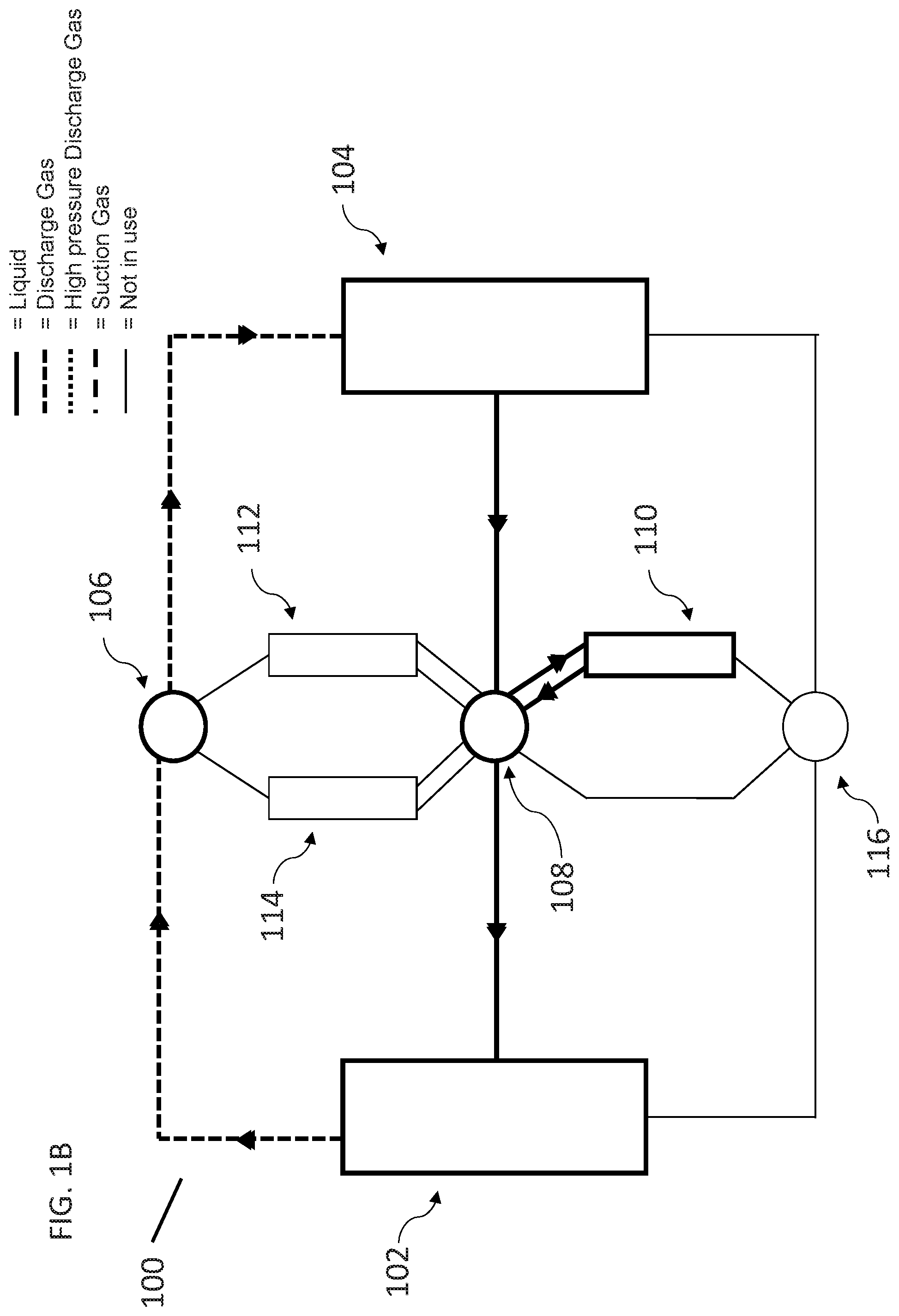
[0061] FIG. 1B depicts the operation of the air conditioning system to provide heating services to the target space 104 with simultaneously heating of the cold thermal store 110. In the illustrated embodiment, the condensing unit 102 is powered and is configured to effectuate a vapor-compression cycle to provide heating services to the target space 104. Concurrently or alternatively, the condensing unit 102 is powered to create heated vapor phase working fluid that can be circulated, e.g. via the discharge gas distributor 106, through the target space 104. The heat transfer that occurs between the heated vapor phase working fluid and the target space 104, typically works to condense the fluid into a liquid, which can then be returned to the condensing unit via the liquid pressurizer and distributor ensemble 108 and can also be used to store heat energy in the cold thermal store 110. In particular, it is depicted that in the illustrated embodiment, the liquid pressurizer and distributor ensemble 108 controls the flow of the working fluid implementing the vapor-compression cycle as well as the condensed fluid that was used to heat the target space 104. In this way, it is possible to shift heat to the cold thermal store 110 so that it can be used as a subcooler. In other words, it is possible to use otherwise unutilized heating by heating the cold thermal store 110. The representational cycle implemented in the configuration shown in FIG. 1B is shown in the enthalpy/pressure diagram shown in FIG. 1C, which shows that after heating the target space 104 using the condensing unit 102, additional heating can be performed on the cold thermal store 110. In summary, additional heating service to the cold thermal store 110 in such embodiments does not require significant additional condensing unit power. The cold thermal store 110 can be used as a source to heat the water store 114, target space 104 or the hot thermal store 112 with reduced condensing unit power if the environmental temperature is below the cold thermal store temperature.
[0062] FIG. 1D illustrates the operation of the air conditioning system to show primary heating service being provided by the condensing unit 102 to the water store 114 via refrigerant condensation while additional heating is provided to the hot thermal store 112 by subcooling. As can be appreciated, the process is similar to that seen in FIGS. 1B and 1C, insofar as the heated vapor phase working fluid that can be circulated, e.g. via the discharge gas distributor 106. However, the illustrated embodiment further depicts that a heated fluid (e.g. compressed vapor phase heating fluid) is generated within the condensing unit and directed to the discharge gas distributor 106, which then redirects the heated gas to the water store 114 and the condensed liquid phase working fluid to the hot thermal energy storage 112 unit, both of which are configured to be operable to absorb the heat, and retain it for subsequent use. In the illustration, this mode of operation does not provide any air conditioning for the target space. In such an embodiment, additional heating service to the hot thermal store 112 doesn't require significant additional condensing unit power. Once the hot thermal store 112 has been heated it can be used as a source to heat the water store 114 or the target space 104 with reduce condensing unit power if the outside environmental temperature is below the hot thermal store 112 temperature.
[0063] FIG. 1E illustrates the operation of the air conditioning system to show primary heating service being provided by the condensing unit 102 to the water store 114 via refrigerant condensation while additional heating is provided to the hot thermal store 112 and cold thermal store 110 by subcooling. As can be appreciated, the process is similar to that seen in FIG. 1D and, insofar as a heated fluid (e.g. compressed vapor phase heating fluid) is generated within the condensing unit and directed to the discharge gas distributor 106, which then redirects the heated gas to the water store 114, which is configured to be operable to absorb the heat, and retain it for subsequent use. However, in addition the liquid pressurizer and distributor ensemble 108 is used to aggregate the condensed fluid that previously served to heat the water store 114 to further heat the hot thermal store 112 and the cold thermal store 110 and to deliver it to the condensing unit for heating and further circulation. In the illustration, this mode of operation does not provide any air conditioning for the target space. In such an embodiment, it is shown that heating the water store 114 can further be combined with simultaneously heating the hot thermal store 112 and cold thermal store 110. The representational cycle implemented in the configuration shown in FIG. 1E is shown in the enthalpy/pressure diagram shown in FIG. 1F, which shows that after heating the water store 114 using the condensing unit 102, additional heating can be provided to the hot and cold thermal stores (112/110).
[0064] FIG. 1G depicts the heating of the target space 104 in conjunction with the simultaneous storing of thermal energy within the hot thermal energy storage unit 112 with the condensing unit 102 via refrigerant condensation while additional heating is provided to the water store 114 by subcooling. FIG. 1G illustrates that a portion of the heated fluid is used to provide heating for the target space 104. In addition, the liquid pressurizer and distributor ensemble 108 is used to aggregate the condensed fluid that previously served to heat the target space 104 and the hot thermal energy storage unit 112 to deliver it to the water store 114 and the condensing unit 102 for heating and further circulation.
[0065] The embodiment illustrated in FIG. 1H depicts the heating of the target space 104 and hot thermal store 112 by the condensing unit 102 via refrigerant condensation, as well as the storage of thermal energy within the water store 114 and cold thermal energy storage unit 110 via subcooling. As can be appreciated, the illustrated operational mode is similar to that seen with respect to FIG. 1G, except that the liquid pressurizer and distributor ensemble 108 is used to heat the cold thermal energy storage unit 110 and the water store 114 simultaneously. In short, this figure provides an embodiment showing the heating of hot thermal store 112 while simultaneously heating the water store 114 and the cold thermal store 110.
[0066] FIG. 1I depicts an embodiment showing the simultaneous heating of the water store 114 services by the condensation unit 102, and the heating of the target space 104 using the hot thermal store 112 as a heat source. In particular, the figure depicts that the working fluid is circulated through the hot thermal energy storage unit 112, the discharge gas distributor 106, into the target space 104 and back to the liquid pressurizer and distributor ensemble 108, while the condensing unit 102 circulates heat through the water store 114 and back to the condensing unit 102 through the liquid pressurizer/distributor ensemble 108. In summary, this configuration allows the heating of the Target space 104 directly from the hot thermal store 112 while the water store 114 is heated by the condensing unit 102 operating in a heat pump configuration.
[0067] FIG. 1J depicts the operation of the air conditioning system to heat the cold thermal store 110 using the condensing unit 102 using condensing unit compressor power. High pressure, high temperature discharge gas is sent from the condensing unit 102 through the suction gas connection 116, is condensed in the cold thermal store 110, and the resulting liquid is sent back to the condensing unit 102 for expansion, evaporation and compression services.
[0068] FIG. 1K depicts the heating of the cold thermal store 110 by the condensing unit 102 without using condensing unit compressor power when the condensing unit heat exchanger is warmer than the cold thermal store 110. In such embodiments, low pressure, warm discharge gas is sent from the condensing unit 102 through the suction gas connection, is condensed in the cold thermal store 110, and the resulting liquid is sent back to the condensing unit 102 for evaporation services.
Configurations for and the Operation of Air Conditioning Systems Incorporating Hot and Cold Thermal Energy Storage Devices with Multiple Discharge Gas Connections
[0069] In many embodiments, air conditioning systems as described in FIGS. 1A to 1K can further incorporate a second discharge gas connection, where the cold thermal store has one suction connection and a bypass connection between the liquid pressurizer/distributor ensemble and the suction gas pressurizer/distributor ensemble.
[0070] In many embodiments, air conditioning systems are configured with a hot thermal store with two discharge connections, a cold thermal store with one suction connection, and a bypass connection between the liquid pressurizer/distributor ensemble and the suction gas pressurizer/distributor ensemble, as illustrated in FIGS. 2A-2C. Note that throughout all of the figures depicted in the instant application, valves may not be explicitly depicted. However, as can be appreciated, valves can be implemented any of the depicted figures to facilitate the desired flow. In any case, FIG. 2A illustrates the configuration and components of an air conditioning system while not in operation; more specifically, FIG. 2A illustrates that an air conditioning system includes a condensing unit 202, a target space 204, a discharge gas distributor ensemble 206, a liquid pressurizer and distributor ensemble 208, a cold thermal energy storage unit 210, a hot thermal store 212, a water store 214, and a suction gas pressurizer and distributor ensemble 216, all of which are operatively interconnected by piping such that a vapor-compression cycle can be implemented to heat or cool the target space using either the condensing unit 202 or the cold or hot thermal energy storage units (210/212), and further configured such that a working fluid can be circulated through the cold or hot energy storage units (210/212), water store 214, and the target space 204 to transport heat as desired. Importantly, within the context of this application, the suction gas pressurizer and distributor ensemble is sometimes referred to as the `suction gas/equalizer ensemble` or `suction gas/equalizer,` or `suction gas equalizer/distributor ensemble`, or `suction gas equalizer/distributor,` or the like. Additionally, within the context of the application, as can be appreciated, references to e.g. low temperature/pressure and high temperature/pressure are relative, and can be understood to be interpreted within the context of a vapor compression cycle.
[0071] FIG. 2B illustrates how the air conditioning system of FIG. 2A can operate to establish/maintain a desired temperature for the targeted space 204 principally using the condensing unit, while simultaneously cooling the hot thermal store 212. In particular, the bolded lines (and arrows) depict the circulation of a working fluid so as to implement a vapor-compression cycle that can cool the target space 204 using the condensing unit 202. More specifically, in the illustrated embodiment, the condensing unit 202 acts to condense incoming vapor phase working fluid that is low pressure, low temperature to a (relatively) high temperature, high pressure liquid phase. As mentioned above, the condensing unit can be implemented via any suitable mechanism(s) in accordance with many embodiments of the invention. The high temperature liquid phase working fluid is then sent to the liquid pressure and distributor ensemble 208 where it is pressurized, if necessary, and directed to the target space 204. At the target space, the working fluid is made to expand so that it experiences a pressure drop and a correlated temperature drop; in this way, the low pressure, low temperature saturated fluid can continue its circulation through the target space and absorb heat from the target space. Consequently, the working fluid is made to evaporate. As mentioned above, the target space can be any suitable space in accordance with certain embodiments of the invention, including but not limited to a living quarters or an evaporator. The low pressure, low temperature vapor phase working fluid is subsequently redirected to the suction gas/equalizer ensemble 216, where it is pressurized, if necessary, and redirected for re-entry into the condensing unit 202, e.g. so that the vapor-compression cycle can continue. At the same time the condensing unit 202 can send low pressure, low temperature vapor phase working fluid through the discharge gas distributor ensemble 206 to cool the hot thermal store 212 and then returned through the discharge gas distributor ensemble 206 back into the condensing unit 202. Accordingly, it is seen how the air conditioning system can implement a vapor-compression cycle using a condensing unit as the heat pump for simultaneously cooling the target space and hot thermal store. Needless to say any suitable working fluid can be implemented. For example, any of a variety of refrigerants can be incorporated. In summary, by cooling the hot thermal store 212, it can later be used economically as a condenser if the environmental temperature exceeds the temperature of the hot thermal store 212.
[0072] The representational cycle implemented in the configuration shown in FIG. 2B is shown in the enthalpy/pressure diagram shown in FIG. 2C, which shows the cooling of the target space 204 and the hot thermal store 212 using the condenser unit 202.
[0073] FIG. 2D depicts an embodiment showing the heating of the water store 214 using the hot thermal store 212 in conjunction with the condensing unit 202. In such embodiments, the hot thermal store 212 may be used as the evaporator instead of the condensing unit 202, which would absorb heat at the outside environmental temperature. Using such embodiments enables a much smaller condensing unit compressor power to be used to heat the water store 214.
[0074] FIG. 2E depicts the simultaneous heating of the water store 214 and the target space 204 using the hot thermal store 212 as a heat source in conjunction with the condensing unit 202. As shown, the operation mode is similar to that seen with respect to FIG. 2D.
Configurations for and the Operation of Air Conditioning Systems Incorporating Hot and Cold Thermal Energy Storage Devices without Water Store
[0075] In many embodiments, an air conditioning system includes distinct hot and cold thermal energy storage units, and is operable to use them to heat and/or cool, a targeted space, but does not include a water store. For example, in many embodiments, a hot thermal energy storage unit is in fluid communication with a discharge gas distributor ensemble in communication with a condensing unit. The condensing unit can be made to implement an operating mode whereby it can boil working fluid such that the vapor phase working fluid can be transmitted to the target space for the purposes of heating. This operating mode can be achieved, for instance, by using a compressor within the condensing unit to compress low temperature gas to high temperature gas. In this way, the condensing unit can be considered to include an integrated heat source, insofar as the integrated compressor can be used to provide heat as desired. In effect, these configurations can operate to store thermal energy within the hot and cold thermal energy units using a powered condensing unit. In this way, a target space can be air conditioned either via the condensing unit, or either of the hot thermal energy storage unit or the cold thermal energy storage unit as appropriate.
[0076] For example, FIGS. 3A-3C depict embodiments of an operation of an air conditioning system that includes separate thermal energy storage units for heating and cooling a target space, in accordance with certain embodiments of the invention. In particular, FIG. 3A illustrates that the air conditioning system is similar to that seen in FIG. 1A insofar as it includes: a condensing unit 302, a target space 304, a liquid pressurizer and distributor ensemble 308, a cold thermal energy storage unit 310, and a suction gas conditioner/distributor 316. FIG. 3A further depicts that the air conditioning system further includes a hot thermal energy storage unit 312, a discharge gas distributor 306 and an additional target space 318. Note that in the illustrated embodiment, the condensing unit 302 is operable to heat (e.g. boil) working fluid so that the heated fluid can be used to heat either the hot thermal energy storage unit 312 or the target space 304. The condensing unit 302, the discharge gas distributor 306, the hot thermal storage unit 312, the target space 304, and the liquid pressurizer and distributor ensemble 308 are operatively connected by piping so as to allow for the circulation of a heated fluid through the target space 304 to heat it, as well as allow the circulation of a heated fluid through the hot thermal energy storage unit 312 to store thermal energy. As can be appreciated, the hot thermal energy storage unit 312 can be implemented in any of a variety of ways. For instance, in many embodiments, the hot thermal energy storage unit includes a heat exchanger element embedded in a phase change material encased in thermal insulation. Further examples of some hot thermal energy storage units that can be incorporated in accordance with embodiments of the invention are discussed below.
[0077] FIG. 3B depicts the operation of the air conditioning system to provide cooling services to the target space 304 using the condensing unit 302. In the illustrated embodiment, the condensing unit 302 is powered and is configured to effectuate a vapor-compression cycle to provide cooling services to the target space 304. Concurrently or alternatively, the condensing unit 302 provides liquid phase refrigerant to cool the cold thermal store 310, e.g. via the liquid pressurizer/distributor ensemble 308 and the suction gas pressurizer/distributor ensemble 316. In the illustrated embodiment, the suction gas pressurizer/distributor ensemble 316 is capable of generate lower pressure suction gas from the cold thermal store 310 while accepting suction gas from target space 304 such as to cool the cold thermal store 310 to a lower temperature. It is also depicted that in the illustrated embodiment, the liquid pressurizer and distributor ensemble 308 controls the flow of the working fluid implementing the vapor-compression cycle as well as the condensed fluid used to cool the target space and charge the cool thermal store 310. In this way, the condensing unit 302 can operate to provide both cooling services to the target space and cooling charge to the cold thermal store 310.
[0078] FIG. 3C illustrates the operation of the air conditioning system shown in FIG. 3A in a mode where by the cold thermal store 310 is not receiving cooling services and instead the suction gas pressurizer/distributor ensemble 316 is used to effectuate cooling services for target space 304 and target space 318 at different temperatures. By utilizing the suction gas pressurizer/distributor ensemble 316 according to embodiments, the nominally 1-stage vapor compression cycle can become a multi-stage cycle, improving the efficiency of the target space cooling operations. This embodiment may be used, in particular, for a version of a refrigeration system factory mounted into a refrigeration rack. In many embodiments, a similar cycle could still be used when the cold thermal store is charging or discharging.
Configurations for and the Operation of Air Conditioning Systems Incorporating Cold Thermal Energy Storage
[0079] In many embodiments, an air conditioning system 400 includes only a cold thermal energy storage 410 unit, in combination with a condensing unit 402, a liquid pressurizer/distributor ensemble 408, and a suction gas conditioner/distributor 416 to cool and/or heat, a targeted space 404. For example, FIG. 4A illustrates an embodiment of an air conditioning system 400 that can utilize the cold thermal energy storage 410 as a subcooler in both heating and cooling modes to enhance the utilization of the cold thermal storage 410.
[0080] FIG. 4B illustrates an embodiment of an air conditioning system from FIG. 4A that can use the cold thermal storage 410 as a subcooler to provide more efficient heating to the target space 404. For example, FIG. 4B depicts the operation of the air conditioning system to provide heating services to the target space 404 with simultaneously heating the cold thermal store 410. In the illustrated embodiment, the condensing unit 402 may be powered and is configured to effectuate a vapor-compression cycle to provide heating services to the target space 404. The heat transfer that occurs between the heated vapor phase working fluid and the target space 404, typically works to condense the fluid into a liquid, which can then be returned to the condensing unit via the liquid pressurizer and distributor ensemble 408 and can also be used to heat the cold thermal store 410. In particular, it is depicted that in the illustrated embodiment, the liquid pressurizer and distributor ensemble 408 controls the flow of the working fluid implementing the vapor-compression cycle as well as the condensed fluid that was used to heat the target space 404. In this way, the condensing unit 402 can operate to provide both heating and cooling. In addition, it is possible to shift heat to the cold thermal store 410 by using it as a subcooler. In such embodiments, the liquid pressurizer and distributor ensemble 408 can then pass the subcooled liquid to the condensing unit 402 where it can be recycled back to the target space. A major benefit of embodiments using the cold thermal store 410 as a subcooler is that unutilized heat energy could be captured and used later to provide more energy efficient heating.
[0081] The representational cycle implemented in the configuration shown in FIG. 4B is shown in the enthalpy/pressure diagram shown in FIG. 4C, which shows that after heating the target space 404 using the condensing unit 402, additional heating can be performed on the cold thermal store 410. In summary, additional heating service to the cold thermal store 410 in such embodiments may not require significant additional condensing unit power. Stored heating in the thermal store 410 can be used as a source to heat the Target space 404 with reduced condensing unit power if the environmental temperature is below the cold thermal store temperature.
[0082] In some embodiments, the cold thermal store 410 may be used for target space cooling as a subcooler in a manner similar to but opposite to the heating method previously described. For example, FIG. 4D illustrates an embodiment of an air conditioning system 400 in use for cooling a target space 404. The liquid pressurizer and distributor ensemble 408 moves the liquid phase working fluid through the cold thermal store to subcool the liquid before it passes to the target space 404. Thus, increasing the cooling capability of the working fluid within the context of a vapor compression cycle. Accordingly, the energy required to cool the working fluid can be reduced as the working fluid absorbs heat from the target space 404 and is moved to the condensing unit 402 by the suction gas pressurizer/distributor ensemble 416. FIG. 4E illustrates the effects of subcooling in the context of target space cooling in an associated enthalpy/pressure diagram. The amount of enthalpy to be gained by the working fluid in the target space cooling is significantly increased by using the cool thermal store to subcool the working fluid.
[0083] Turning now to FIG. 4F some embodiments may use the cold thermal store 410 as an evaporator during the heating of the target space 404. The cold thermal store can act to provide heat to the expanded low pressure, low temperature working fluid provided by the target space 404 thereby heating or evaporating the working fluid while simultaneously cooling the cold thermal store. 410. Subsequently, the suction gas pressurizer/distributor ensemble 416 can direct the vapor phase working fluid to the condensing unit which would require reduced condensing power usage to provide a heated vapor to the target space.
[0084] In other embodiments, the condensing unit 402 may be used in to heat the cold thermal store 410 by working in connection with the suction gas pressurizer/distributor ensemble 416 to pull heated discharge gas from the condensing unit 402 and distributing it to the cold thermal store 410. For example, FIG. 4G illustrates a working flow of how such embodiments may be implemented in accordance with embodiments of the invention. Such embodiments can act to heat the cold thermal store while simultaneously cooling the working fluid provided to the condensing unit 402. Accordingly, FIG. 4H illustrates the enthalpy/pressure diagram of embodiments where the cold thermal store 410 is heated by the hot discharge gas from the condensing unit. Such embodiments can allow for higher heating rates of the cold thermal store 410 for later heating of the target space 404.
[0085] Similar to FIG. 4H, FIG. 4I illustrates an embodiment of heating the cold thermal store 410 to achieve improved condensing unit efficiency. However, in such embodiments, the heating is managed by using the suction gas pressurizer/distributor ensemble 416 to distribute a warmed gas generated without the condensing unit 402 compressor operation to the cold thermal store 410. Such embodiments can function similar to subcooling in the heating process of the cold thermal store 410.
[0086] Accordingly, FIG. 4J illustrates the enthalpy/pressure diagram of embodiments where the cold thermal store 410 is heated by the warmed suction gas from the condensing unit. Such embodiments can allow the cold thermal store 410 to absorb heat provided by the ambient environment with minimal power consumption by the condensing unit 402 for later economic heating of the target space 404 when ambient temperatures become lower than the temperature of the cold thermal store.
Configurations for and the Operation of Air Conditioning Systems Incorporating Cold Thermal Energy Storage in Conjunction with a Water Store
[0087] In accordance with many embodiments, the air conditioning system as illustrated above may be augmented with other components that can aid in the efficiency of heating and cooling. For example, FIG. 5A illustrates an embodiment of an air conditioning system 500 that uses a cold thermal store 510 but may also incorporate the use of a water store 514. In many embodiments, the water store 514 may be operatively connected to the condensing unit as well as the target space 504 through piping connected to a discharge gas distributor ensemble 506 and a liquid pressurizer and distributor ensemble 508. In accordance with some embodiments, the condensing unit 502 can be made to implement an operating mode whereby it can boil working fluid such that the vapor phase working fluid can transmit heat to the water store. This operating mode can be achieved, for instance, by using a compressor within the condensing unit to compress low temperature gas to high temperature gas. In this way, the condensing unit can be considered to include an integrated heat source, insofar as the integrated, expansion valve, evaporator and compressor can be used to convert liquid phase working fluid to high temperature, high pressure working fluid as desired. In effect, these configurations can operate to store thermal energy within the water store 514 and cold thermal store 510 using a powered condensing unit. In this way, a target space can be air conditioned either via the condensing unit 502, or the cold thermal energy store 510 unit as appropriate.
[0088] Many such embodiments can be illustrated by the flow of working fluid diagram in FIG. 5B. The water store 514 is heated by the discharge gas from the condensing unit 502 while simultaneously the cold thermal store 510 expands and evaporates the working fluid and receives cooling services. In addition, liquid phase working fluid can be further subcooled by low temperature, low pressure suction gas internally in the condensing unit 502. The two processes illustrated in FIG. 5B act to simultaneously heat the water store 514 and cool the cold thermal store 510 according to many embodiments.
[0089] In other embodiments, illustrated in FIG. 5C the cold thermal store can be used to subcool the working fluid as it is removed from the water store 514 by way of the liquid pressurizer and distributor ensemble 508 and subsequently moved through the cold thermal store 510 and distributed to the condensing unit. Such embodiments can act to capture the remaining heat from the working fluid in the cold thermal store 510 to be used at a later time and help to reduce the condensing unit power requirements to heat the water store, or, although not shown, for heating the target space 504.
[0090] Similar to FIG. 5B, FIG. 5D illustrates that in some embodiments no subcooling in the condensing unit 502 is effectuated.
Embodiments of a Condensing Unit for Use in Air Conditioning Systems
[0091] As previously discussed, many air conditioning systems may implement a condensing unit to pressurize and/or condense received low pressure, low temperature vapor phase working fluid (e.g. exiting from a target space and/or a thermal energy storage unit such that it changes phase to a high temperature, high pressure liquid, e.g. within the context of a vapor-compression cycle. For example, FIGS. 6A-6I illustrate embodiments of a condensing unit and operational formats of such embodiments for use within the context of a vapor-compression cycle. FIG. 6A illustrates an embodiment of a condensing unit 600 that comprises a compressor 602 (operable to compress received vapor phase working fluid) and a condenser/evaporator 604 to condense the high pressure vapor phase working fluid to a liquid phase working fluid or evaporate the low pressure liquid phase working fluid to a vapor phase working fluid depending on the mode of operation. Many embodiments may include other components for operation within the context of a vapor-compression cycle and an air conditioning system such as an expansion valve 606 and one or more additional valves (not shown) to direct the flow of the working fluid into and out of the condensing unit 600. Additionally, although not show, some embodiments may incorporate a power source such that the condensing unit 600 has a power supply so that it can utilize external power to operate the various components within the unit.
[0092] As can be understood by embodiments of an air conditioning system, many embodiments of a condensing unit 600 may be configured to function in one or more manners or modes of operation within the context of a vapor-compression cycle. For example, FIG. 6B illustrates an embodiment where the condensing unit 600 operates to send a discharge gas through suction or a discharge connection (not shown) with the discharge gas going to suction. Many such embodiments may operate where the condenser/evaporator 604 receives a low pressure liquid phase working fluid and evaporates it into a vapor phase working fluid subsequently transferring the vapor phase working fluid to a compressor 602 that compressed the vapor phase working fluid into a high pressure high temperature vapor. Directional flows of a working fluid, can be further illustrated by the corresponding flow lines shown in FIGS. 6B to 6D. Accordingly, some embodiments may operate in manner similar to that shown in FIG. 6C, where a discharge gas is sent through a suction or discharge connection with the discharge gas going to discharge. In other embodiments, the working fluid may be evaporated and sent out as warmed suction gas as illustrated in FIG. 6D.
[0093] In accordance with many embodiments, the condensing unit 600 may incorporate other components with one or more fluid connections that can help improve the functionality of the condensing unit. For example, FIG. 6E illustrates an embodiment of a condensing unit 600 with the addition of a liquid suction line heat exchanger 608. As can be appreciated, the suction line heat exchanger 608 may be capable of providing suction gas warming for the compressor 602 as well as liquid cooling for the condenser/evaporator 604 in any desired mode of operation, such as heating or cooling a target space or one or more thermal energy stores.
[0094] In some embodiments, the liquid suction line heat exchanger may operate to transfer heat between the liquid line 610 and the suction line 612 within the context of a vapor-compression cycle and/or embodiments of an air conditioning system. Accordingly, some embodiments may only implement a single discharge line 614. FIG. 6F illustrates an exemplary embodiment of a condensing unit 600 outfitted with a liquid suction line heat exchanger 608 in an embodiment of a mode of operation with various suction and discharge lines so indicated. In accordance with many embodiments, condensing units may also incorporate more than one discharge line 614, as illustrated in FIGS. 6G and 6H.
[0095] Referring now to FIG. 6I, it can be appreciated that some embodiments of a condensing unit 600 may not be conformed within a single form factor. For example, as illustrated in FIGS. 6A-6H some embodiments may place the components of a condensing unit within a single form factor which may be desirable for some operations or configurations. However, many embodiments may create a separate enclosure 601 for the condenser/evaporator 604 and the expansion valve 606. Although some embodiments may use one or more enclosures for the various components of a condensing unit 600, it should be understood that the combination of components, regardless of form factor is what may be considered the condensing unit 600.
Embodiments of a Water Store for Implementation within Air Conditioning Systems
[0096] In many embodiments, water stores 700 may be implemented that are suitable to be incorporated within many of the above described air conditioning system configurations. For example, FIG. 7A depicts an embodiment of a water store 700 with various components that help to effectuate the energy transfer to/from the working fluid. Some embodiments of a water store 700 may include a tank 702 capable of holding a specified volume of water. In accordance with many embodiments, a heat exchanger 704 may be positioned within the water store such that it may transfer the heat to/from the working fluid to/from the water within the tank 702. In many embodiments, the water may be supplied or removed by one or more valves 708. Additionally, many embodiments may incorporate an immersion heater 706 that may be positioned within the water as an alternative method of heating the water within the tank 702.
[0097] In accordance with many embodiments, the heat exchanger 704 may be in the form of heat exchanging coils that are present within a tank volume 702. In such embodiments, a heat pump water tank configuration is implemented whereby hot gaseous refrigerant is sent through the coils, condenses and transfers heat into the volume of water contained in the tank. In other embodiments, as shown in FIG. 7B, a water store 700 is provided whereby a heat exchanger 704 is located outside of the tank volume 702 and is connected to a circulation pump 710. The circulation pump 710, in accordance with many embodiments, is configured to pump water from the tank volume 702 through the heat exchanger 704 where the heat exchanger 704 can subsequently transfer thermal energy to/from the working fluid. Having such a separate heat exchanger allows the water store to be used as a heat pump hot water heater or to enable the scavenging of heat from the water previously heated by a gas burner for the purposes of space heating.
Embodiments of a Cold Thermal Store for Implementation in Air Conditioning Systems
[0098] Turning now to FIGS. 8A-8D embodiments of a cold thermal store and various modes of operation are illustrated. For example, FIG. 8A illustrates an embodiment of a cold thermal store 800 with a heat exchanger 802 that is embedded in a phase change material. In many embodiments, the phase change material may be any number of materials suitable for efficient thermal energy transfer. In many embodiments, the cold thermal store 800 may also be configured with an expansion valve and one or more flow control valves (not shown) that may control the flow of fluid into and out of the cold thermal store 800. Additional embodiments may include a bypass line 806 that is configured to bypass the expansion valve in accordance with various modes of operation.
[0099] FIG. 8B illustrates an embodiment of a cold thermal store 800 with two liquid connections 810 to illustrate the capability of the cold thermal store 800 to move fluid through the component and return to a liquid pressurizer/dispensing ensemble (not shown). For example, the embodiment shown in FIG. 8B illustrates a cold thermal store in a cooling or freezing phase. In such embodiments, a liquid phase working fluid enters the cold thermal store 800 and is expanded to a low temperature and low pressure through the expansion valve 804. The heat exchanger 802 subsequently operates to evaporate the working fluid to a low temperature low pressure vapor phase suction gas that can then be redistributed to various components of an air conditioning system. In other words, FIG. 8B illustrates cooling services being provided in the cold thermal store 800 for future use.
[0100] For example, FIG. 8C illustrates a mode of operation of a cold thermal store 800 where the cold thermal store 800 may be operable to provide cooling services to a target space by condensing a suction gas to a low temperature low pressure liquid.
[0101] Alternatively, some embodiments many be operable to provide cooling or heating of the cold thermal store based on the temperature of the entering working fluid as illustrated in FIG. 8D. In these embodiments the cold thermal store 800 may be utilized as a subcooler to cool the working fluid to such a temperature that a condensing unit (not shown) would not be required to use as much condensing unit power as is illustrated by the flow in FIG. 8D.
[0102] In accordance with many embodiments, it should be understood that many embodiments of an air conditioning system and various components used therein may implement additional elements such as control systems and mechanisms that can allow for embodiments to be utilized at different times to take advantage of the efficiencies of the embodiments of the invention. For example, many embodiments may incorporate computer control systems to control various elements of embodiments of the invention, such as the cold thermal store, such that they can be used in the most efficient manner possible, such as during peak or off-peak energy usage times.
Ejectors for Implementation within Air Conditioning Systems
[0103] In many embodiments, configurations of ejectors are implemented that are suitable to be incorporated within many of the above described air conditioning system configurations.
[0104] Conventional systems use normal pumps in combination with a special valve ejector. In a vapor compression cycle the most efficient configuration uses an expander (high pressure liquid), which provides no entropy gain. However, expanders are expensive and complex so it is preferable to use a simple expansion valve. However, the use of simple expansion valves destroys usable work in the process of expanding the fluid and reduces the cycle efficiency. An ejector enables work that would otherwise be lost to be transferred to another fluid. In practice high pressure fluid would go into a valve and expand, but would create a low pressure region to suck in other fluids and create high pressure fluids. The biggest drawback to the use of expansion valves is that their performance is dependent on the internal geometry and dimensions. Accordingly, a single fixed geometry can't operate across a wide variety of conditions. In the current system it is possible to know what pressure addition is needed and the relative mass flow rates. Accordingly, in many embodiments the inlet condition is configured so the ejector sees the same condition, such as, for example, by cooling the injector and increasing the pressure to an arbitrarily high pressure.
[0105] In many embodiments, as shown in FIGS. 9A and 9B, to make steady flow rate a bank of expansion valves are provided that can be opened and closed as needed to maintain a suitable mass flow rate. In particular, in the embodiment shown in FIG. 9A, an ejector bank 902 is configured utilizing a subcooling heat exchanger 904, and a hydraulic accumulator 906. In such an embodiment the fluid goes to the subcooler 904 and is then pressurized with a pump 908 and the pressure is maintained by the hydraulic accumulator 906. Depending on the capacity needed for a particular operation, a suitable number of ejectors can be opened and closed. Alternatively, as shown in FIG. 9B, in other embodiments the temperature and pressure control in the system is controlled by implementing a bypass valve 910 between the pump 908 and reservoir 912.
[0106] FIG. 9C provides a enthalpy/pressure diagram depicting the processes of subcooling and pressurizing inlet refrigerant to the ejector bank so as to provide fixed inlet conditions irrespective of the initial liquid temperature or pressure. As discussed, the performance of an ejector is highly dependent on its geometry in relation to the inlet conditions of the inlet streams. The difficulty utilizing ejectors in vapor compression cycles to date have been the wide array of inlet conditions they are exposed to, causing performance to vary drastically. By fixing ejector inlet conditions, the mass flow rate of the two inlet streams and the pressure boost the value is required to provide, a performant valve geometry can be identified. Using the embodiments of FIGS. 9A and 9B it is possible to cool and pressurize the liquid such that a desired fluid pressurization can be attained (as shown in by the star in FIG. 9C). FIG. 9D provides a P-h diagram depicting the ejector process of combining an inlet stream with a motivating stream to boost the pressure of the inlet stream, in accordance with embodiments. FIG. 9E provides a P-h diagram depicting an ejector based vapor compression cycle, in accordance with embodiments, where the ejector operating conditions are unaffected by the condensing pressure required by the cycle.
[0107] FIG. 10A provides an embodiment of an HVAC system incorporating an ejector system as shown in FIGS. 9A and 9B. As shown, many such embodiments incorporate a condensing unit 1002, a liquid pressurizer/dispensing ensemble 1008, a cold thermal store 1010, a target space 1004 and suction gas pressurizer/distributor ensemble 1016 whereby the cold thermal store 1010 is able to be cooled to a lower temperature than the target space 1004 through the use of an ejector that is provided inlet refrigerant streams of a controlled inlet pressure and temperature.
[0108] FIG. 10A illustrates the operation of an embodiment of an HVAC system incorporating an ejector system as shown in FIG. 10A where the cold thermal store 1010 and target space 1004 are both receiving cooling services and the cold thermal store 1010 is being cooled to a lower temperature than the target space 1004.
DOCTRINE OF EQUIVALENTS
[0109] While several alternative configurations for robust air conditioning systems have been depicted, it should be clear that any of a variety of robust air conditioning system configurations can be implemented in accordance with many embodiments of the invention.
[0110] More generally, as can be inferred from the above discussion, the above-mentioned concepts can be implemented in a variety of arrangements in accordance with embodiments of the invention. Accordingly, although the present invention has been described in certain specific aspects, many additional modifications and variations would be apparent to those skilled in the art. It is therefore to be understood that the present invention may be practiced otherwise than specifically described. Thus, embodiments of the present invention should be considered in all respects as illustrative and not restrictive.
* * * * *
D00000
D00001
D00002
D00003
D00004
D00005
D00006
D00007
D00008
D00009
D00010
D00011
D00012

D00013

D00014

D00015

D00016
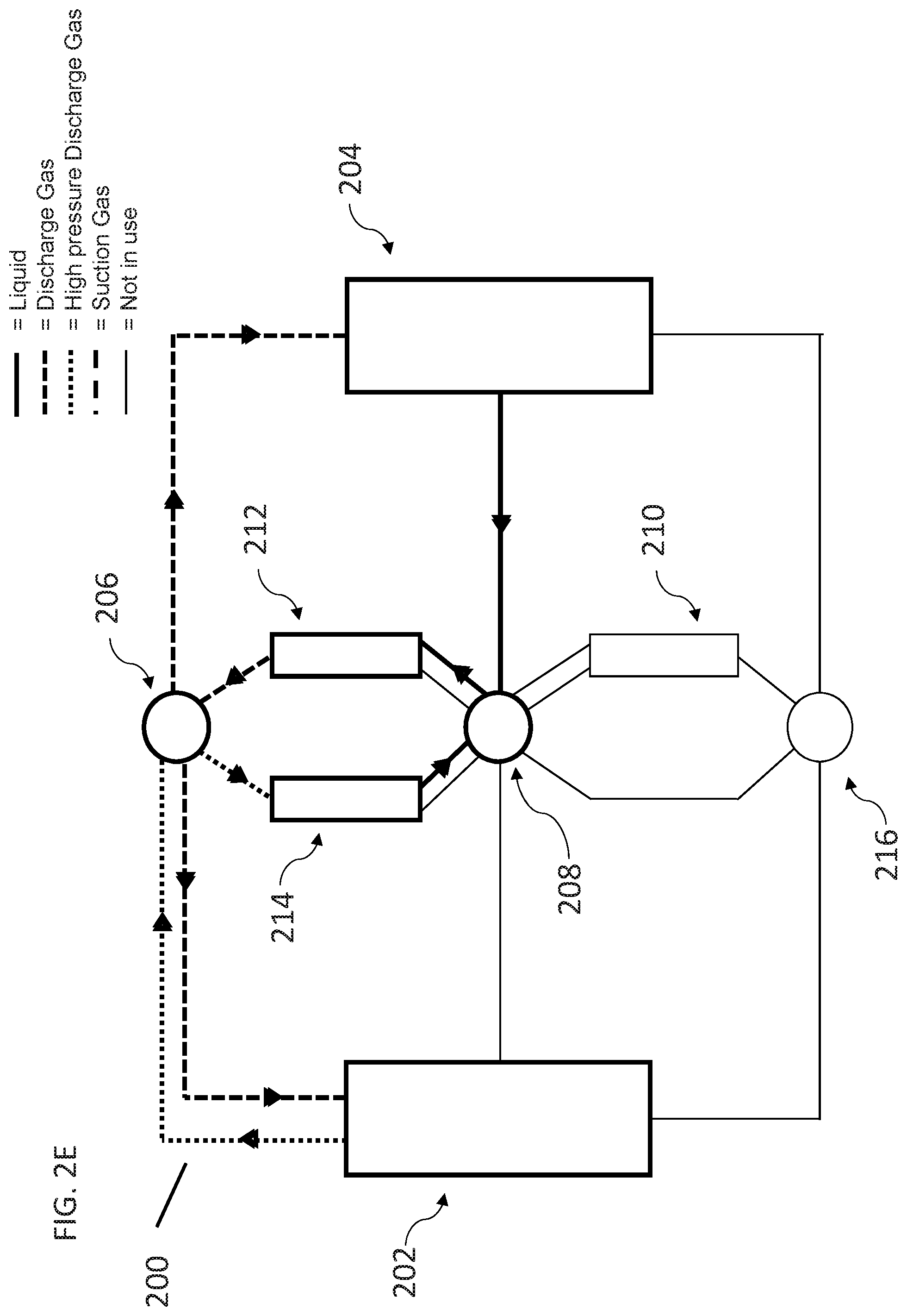
D00017

D00018

D00019

D00020

D00021

D00022

D00023

D00024
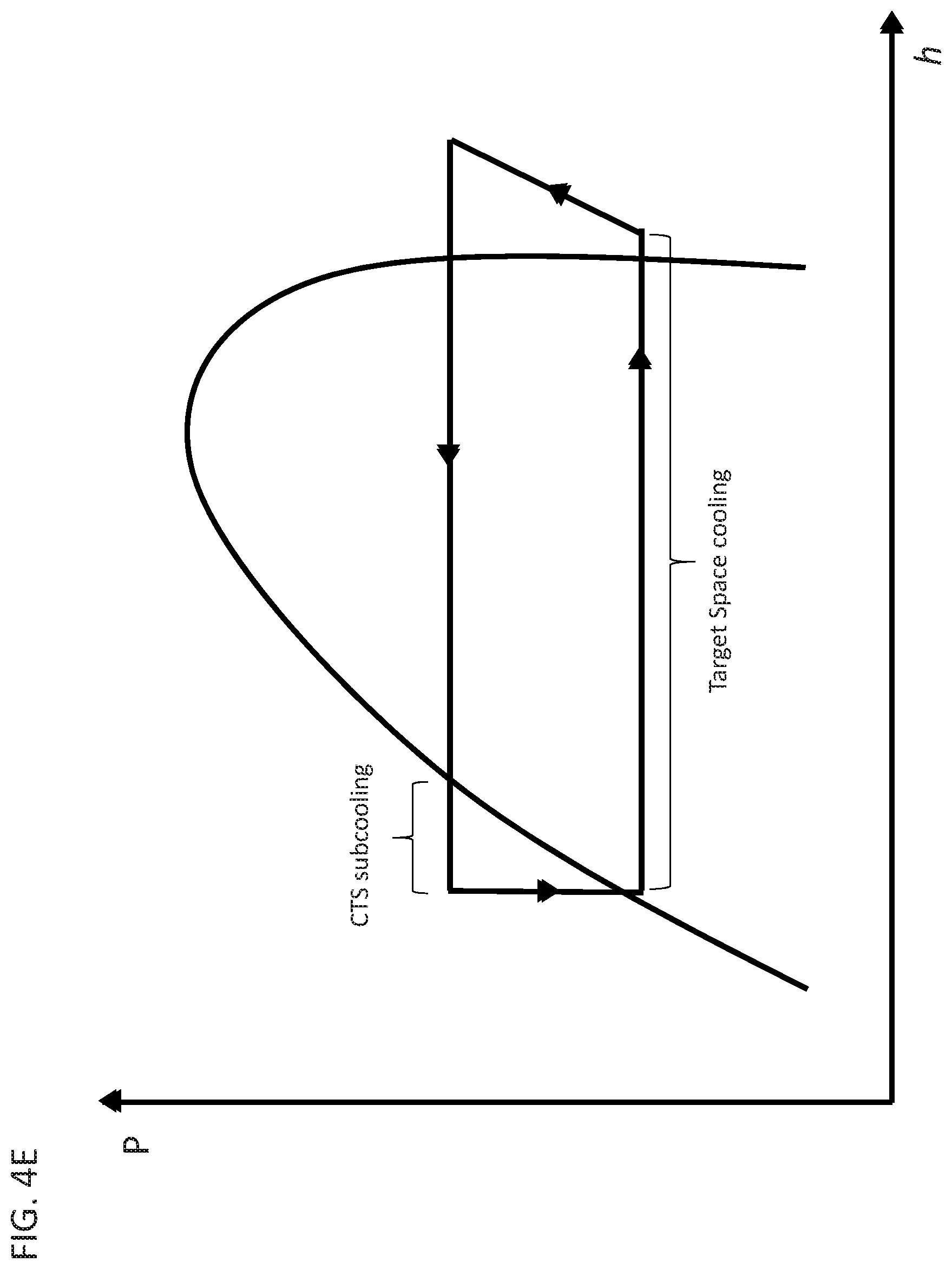
D00025

D00026

D00027

D00028

D00029

D00030
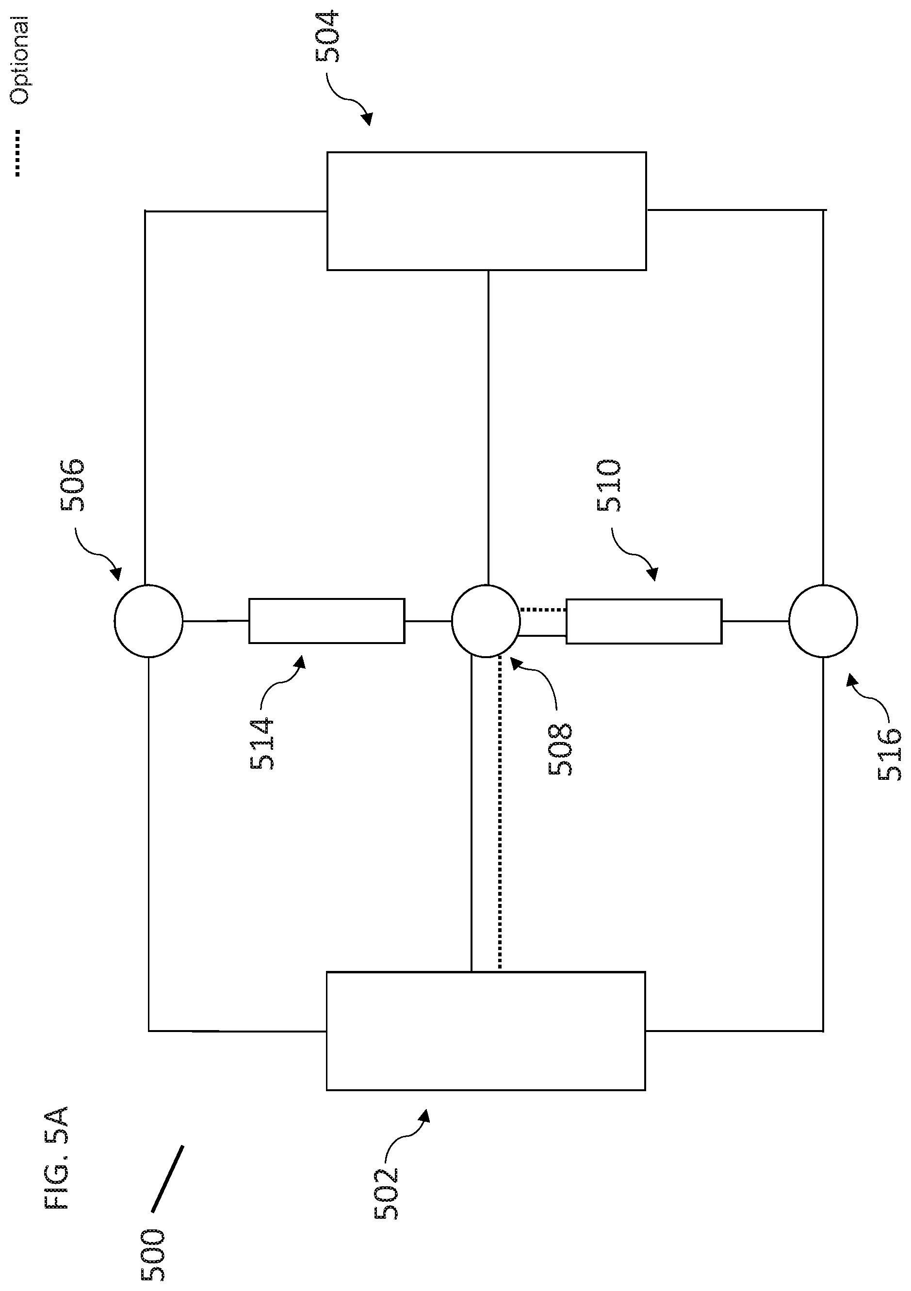
D00031

D00032
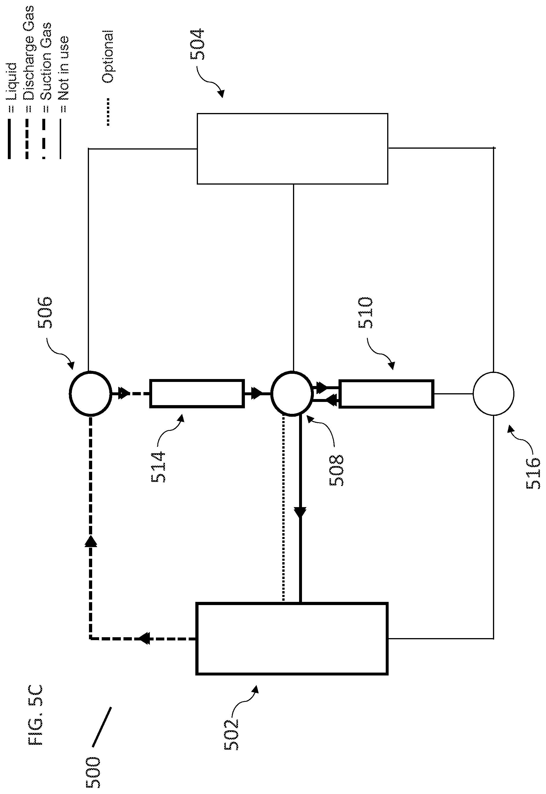
D00033
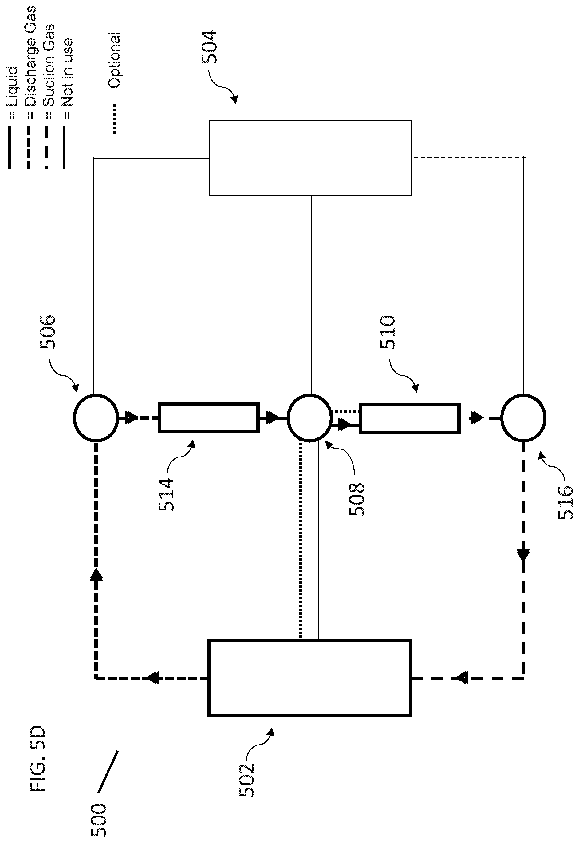
D00034
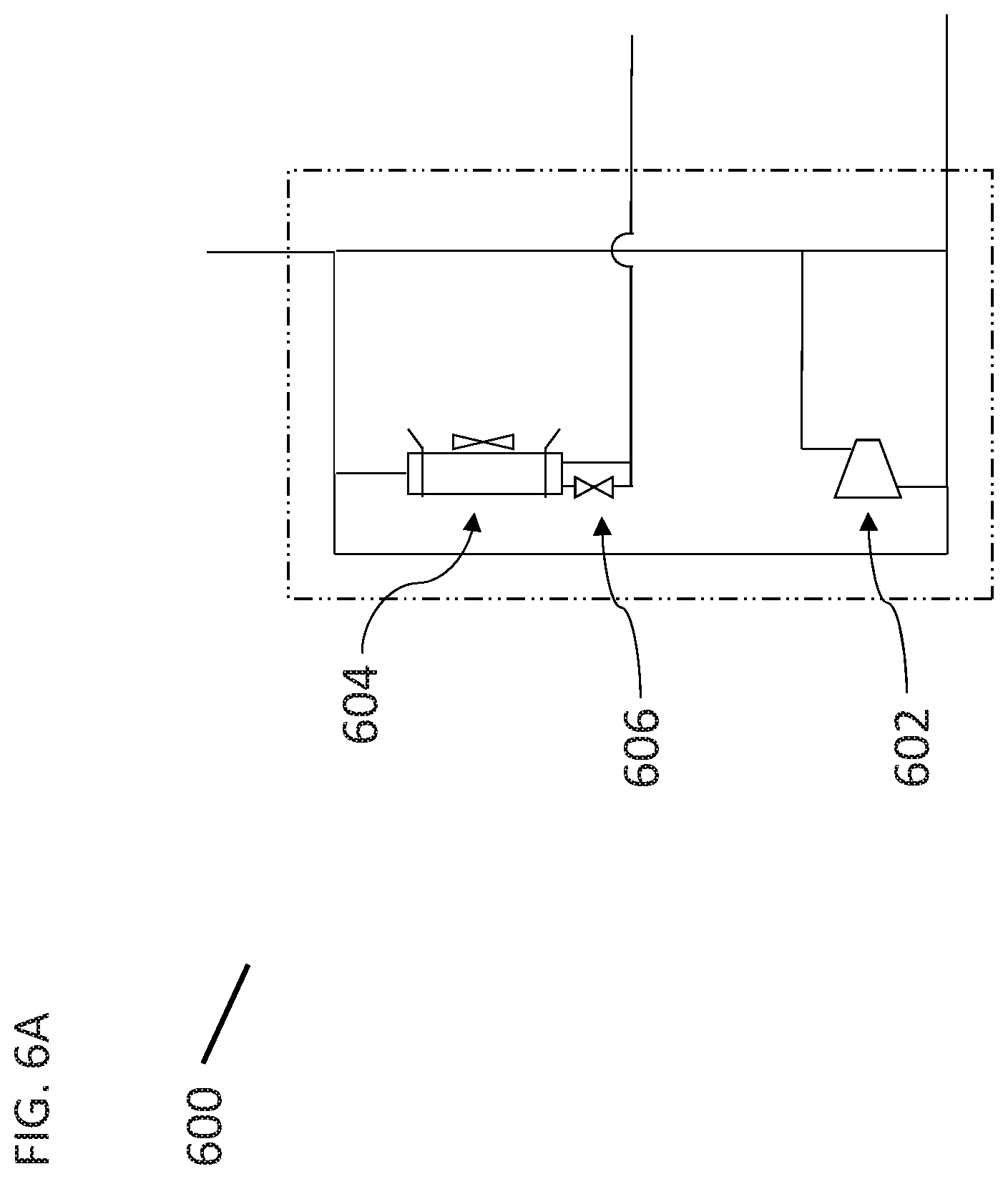
D00035

D00036

D00037

D00038

D00039

D00040

D00041

D00042
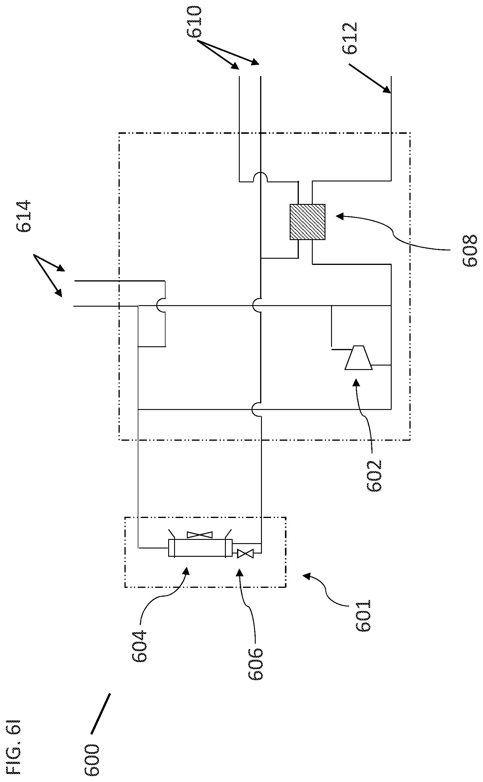
D00043

D00044

D00045

D00046

D00047
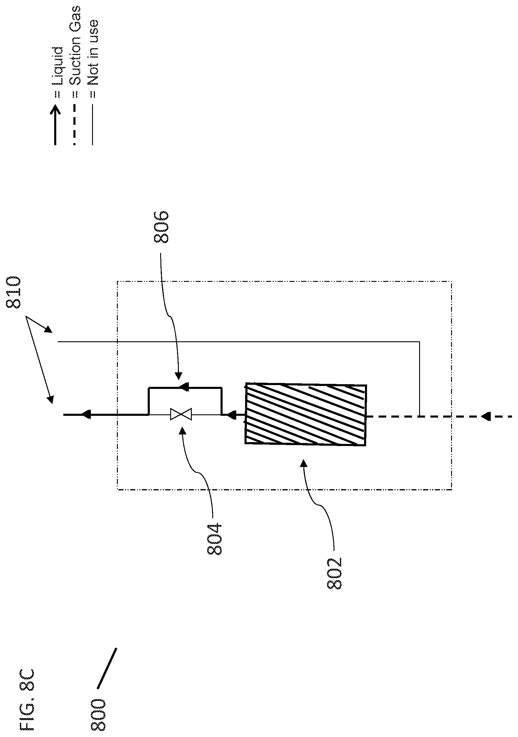
D00048

D00049

D00050

D00051

D00052

D00053
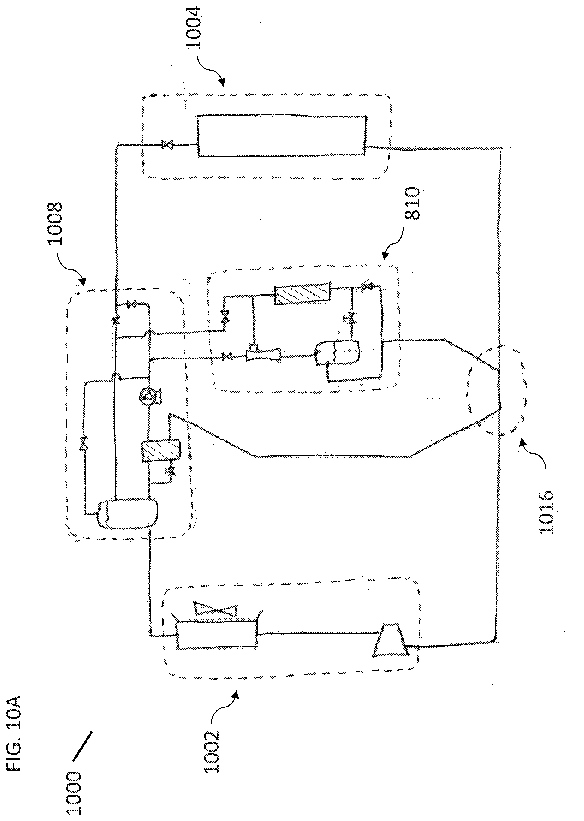
D00054

XML
uspto.report is an independent third-party trademark research tool that is not affiliated, endorsed, or sponsored by the United States Patent and Trademark Office (USPTO) or any other governmental organization. The information provided by uspto.report is based on publicly available data at the time of writing and is intended for informational purposes only.
While we strive to provide accurate and up-to-date information, we do not guarantee the accuracy, completeness, reliability, or suitability of the information displayed on this site. The use of this site is at your own risk. Any reliance you place on such information is therefore strictly at your own risk.
All official trademark data, including owner information, should be verified by visiting the official USPTO website at www.uspto.gov. This site is not intended to replace professional legal advice and should not be used as a substitute for consulting with a legal professional who is knowledgeable about trademark law.