Scroll-type Compressor
HIRATA; Hirofumi ; et al.
U.S. patent application number 16/471292 was filed with the patent office on 2020-01-16 for scroll-type compressor. The applicant listed for this patent is MITSUBISHI HEAVY INDUSTRIES, LTD.. Invention is credited to Hirofumi HIRATA, Takahide ITO, Keita KITAGUCHI, Makoto TAKEUCHI, Takuma YAMASHITA.
| Application Number | 20200018310 16/471292 |
| Document ID | / |
| Family ID | 62627030 |
| Filed Date | 2020-01-16 |


| United States Patent Application | 20200018310 |
| Kind Code | A1 |
| HIRATA; Hirofumi ; et al. | January 16, 2020 |
SCROLL-TYPE COMPRESSOR
Abstract
Provided is a pin-ring mechanism (26) that supports a driving-side scroll member and a driven-side scroll member such that the driving-side scroll member and the driven-side scroll member are in relative revolving motion. The pin-ring mechanism (26) includes: a pin member (30); a ring member (34) that has an inner ring (34b) which comes into contact with the pin member (30), a plurality of balls (34c) which roll on the inner ring (34b), and a retainer (34d); and a bush 36 that is disposed on an inner periphery of the inner ring (34b), and receives a component of force in a circumferential direction of the inner ring (34b) from the pin member (30) to rotate together with the inner ring (34b).
| Inventors: | HIRATA; Hirofumi; (Tokyo, JP) ; ITO; Takahide; (Tokyo, JP) ; TAKEUCHI; Makoto; (Tokyo, JP) ; YAMASHITA; Takuma; (Tokyo, JP) ; KITAGUCHI; Keita; (Tokyo, JP) | ||||||||||
| Applicant: |
|
||||||||||
|---|---|---|---|---|---|---|---|---|---|---|---|
| Family ID: | 62627030 | ||||||||||
| Appl. No.: | 16/471292 | ||||||||||
| Filed: | November 9, 2017 | ||||||||||
| PCT Filed: | November 9, 2017 | ||||||||||
| PCT NO: | PCT/JP2017/040451 | ||||||||||
| 371 Date: | June 19, 2019 |
| Current U.S. Class: | 1/1 |
| Current CPC Class: | F04C 18/0215 20130101; F01C 1/0215 20130101; F04C 18/023 20130101; F04C 18/0246 20130101 |
| International Class: | F04C 18/02 20060101 F04C018/02 |
Foreign Application Data
| Date | Code | Application Number |
|---|---|---|
| Dec 21, 2016 | JP | 2016-247918 |
| Jan 24, 2017 | JP | 2017-010245 |
Claims
1. A scroll-type compressor comprising: a first scroll member that has a spiral first wall body disposed on a first end plate; a second scroll member that has a second wall body disposed on a second end plate and corresponds to the first wall body, and forms a compression space in engagement with the first wall body; and a synchronous driving mechanism that supports the first scroll member and the second scroll member such that the first scroll member and the second scroll member are in relative revolving motion, wherein the synchronous driving mechanism includes: a pin member that is fixed to the first wall body and/or the second wall body, and protrudes toward the second end plate and/or the first end plate which the pin member faces; a ring member that has an inner ring which is fixed to the first end plate and/or the second end plate, and which comes into contact with the pin member, a plurality of rolling bodies which roll on the inner ring, and a retainer which holds respective relative positions of the rolling bodies; and an intermediate member that transmits circumferential power from the pin member to the inner ring.
2. The scroll-type compressor according to claim 1, wherein the intermediate member is disposed on an inner periphery of the inner ring, and rotates together with the inner ring.
3. The scroll-type compressor according to claim 2, wherein the intermediate member is in a substantial disk shape formed so as to come into contact with the inner periphery of the inner ring, and is provided with a cutout having a clearance between the pin member and the intermediate member at a position corresponding to the pin member.
4. The scroll-type compressor according to claim 1, wherein the intermediate member is an elastic member provided on an outer periphery of the pin member.
5. The scroll-type compressor according to claim 4, wherein the elastic member is disposed at a central position in an axial direction of the inner ring.
6. The scroll-type compressor according to claim 1, wherein a rolling bearing that supports the pin member rotatably around an axis is provided between the pin member, and the first wall body and/or the second wall body to which the pin member is fixed.
7. The scroll-type compressor according to claim 6, wherein the intermediate member is made of resin, and the pin member is made of metal.
Description
TECHNICAL FIELD
[0001] The present invention relates to a scroll-type compressor.
BACKGROUND ART
[0002] Conventionally, a co-rotating scroll compressor has been known as one form of a scroll-type compressor (refer to PTL 1). This includes a driving-side scroll, and a driven-side scroll that rotates in synchronization with the driving-side scroll, in which a driven shaft that supports rotation of the driven-side scroll is offset by a turning radius with respect to a driving shaft that rotates the driving-side scroll, and the driving shaft and the driven shaft are rotated in the same direction at the same angular velocity. A synchronous driving mechanism that transmits driving force from a driving-side scroll member to driven-side scroll member such that the driving-side scroll member and the driven-side scroll member are in rotating motion in the same direction at the same angular velocity is provided.
CITATION LIST
Patent Literature
[PTL 1]
[0003] the Publication of Japanese Patent No. 4556183
SUMMARY OF INVENTION
Technical Problem
[0004] In a case in which a pin-ring mechanism having a pin member and a ring member are employed as the synchronous driving mechanism, and the ring member is a rolling bearing, there are the following problems.
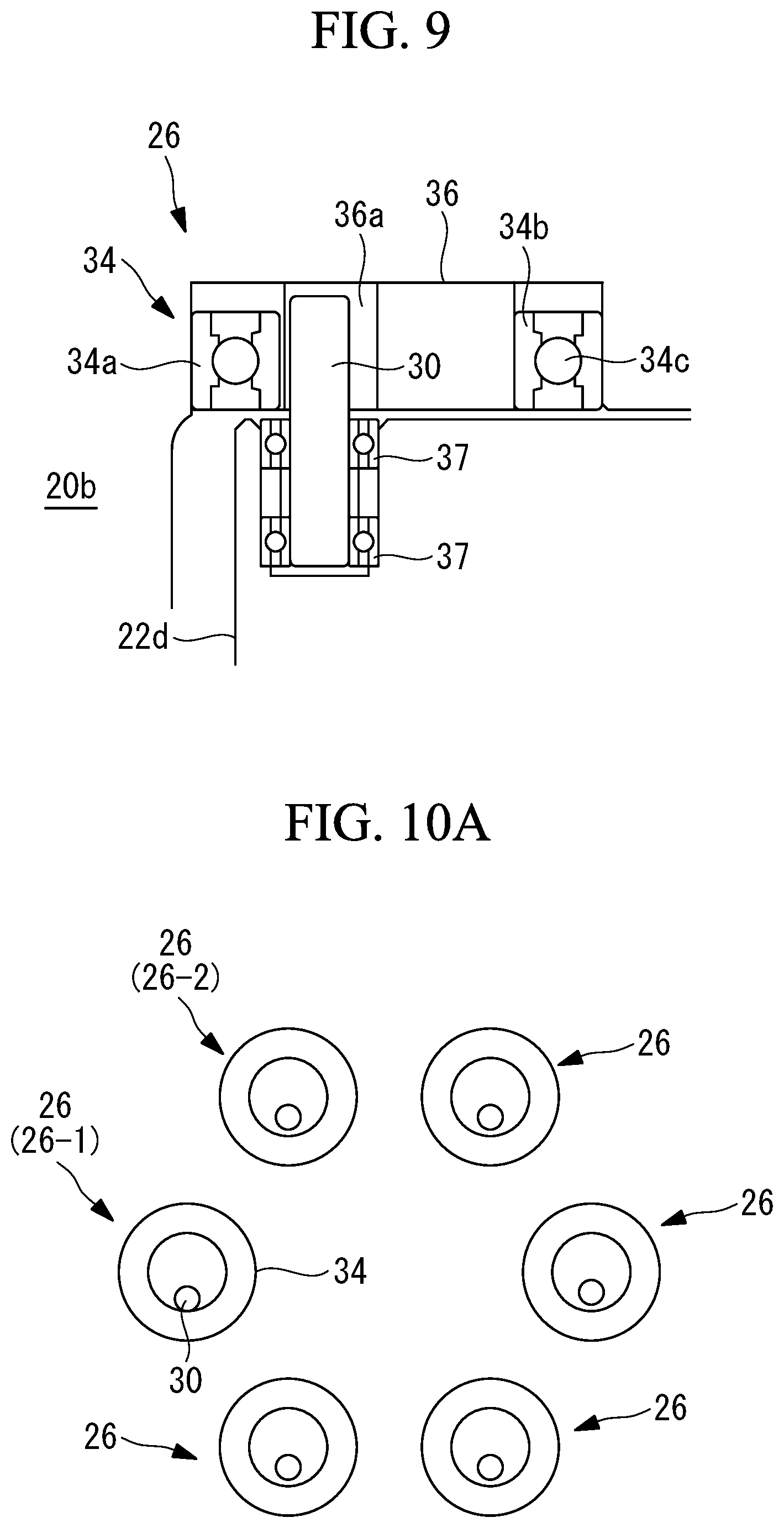
[0005] In FIG. 10A and FIG. 10B, a case in which six pin-ring mechanisms 26 are disposed is illustrated. Each pin-ring mechanism 26 is responsible for transmission of power between a corresponding pin member 30 and a corresponding ring member 34 of power per angle range. In a case of the six pin-ring mechanisms 26, each pin-ring mechanism 26 is responsible for power transmission of 60.degree. (=360.degree.=6). For example, in the case of FIG. 10A, the left lower pin-ring mechanism 26-1 in the drawing is responsible for power transmission. When each scroll member rotates by a predetermined angle, each scroll member moves to a position illustrated in FIG. 10B, and power transmission is taken over by the pin-ring mechanism 26-2 adjacent to the pin-ring mechanism 26-1. At this time, in a case in which each ring member 34 is a rolling bearing, when the pin member 30 and an inner ring of the ring member 34 come into contact with each other, only a rolling body corresponding to the contact position is urged to roll, and other rolling bodies each tend to be kept in a stationary state. Consequently, this prevents rolling of the rolling body corresponding to a position where contact is made with pin member 30. A load is then applied to a retainer holding each rolling body, and the retainer may be damaged.
[0006] In a case in which the pin-ring mechanism having the pin member and the ring member are employed as the synchronous driving mechanism, the pin member is press-fitted to a scroll member to be fixed in an immobile state. Therefore, there is a problem that when the pin member transmits power, wear is caused between the pin member and a mating member with which the pin member comes into contact, thus shortening the life of the synchronous driving mechanism.
[0007] An object of the present invention, which has been made in view of such circumstances, is to provide a scroll-type compressor including a synchronous driving mechanism in the form of a rolling bearing, which is capable of reducing a load to be applied to a retainer.
[0008] Additionally, an object of the present invention is to provide a scroll-type compressor including a synchronous driving mechanism capable of preventing shortening of life due to contact with the pin member.
Solution to Problem
[0009] In order to solve the aforementioned problem, a scroll-type compressor of the present invention employs the following solutions.
[0010] That is, a scroll-type compressor according to an aspect of the present invention includes: a first scroll member that has a spiral first wall body disposed on a first end plate; a second scroll member that has a second wall body disposed on a second end plate and corresponds to the first wall body, and forms a compression space in engagement with the first wall body; and a synchronous driving mechanism that supports the first scroll member and the second scroll member such that the first scroll member and the second scroll member are in relative revolving motion, wherein the synchronous driving mechanism includes: a pin member that is fixed to the first wall body and/or the second wall body, and protrudes toward the second end plate and/or the first end plate which the pin member faces; a ring member that has an inner ring which is fixed to the first end plate and/or the second end plate, and which comes into contact with the pin member, a plurality of rolling bodies which roll on the inner ring, and a retainer which holds respective relative positions of the rolling bodies; and an intermediate member that transmits circumferential power from the pin member to the inner ring.
[0011] The first wall body disposed on the first end plate of the first scroll member and the corresponding second wall body of the second scroll member engage with each other. The synchronous driving mechanism is provided between the first scroll member and the second scroll member such that the respective scroll members are in relative revolving motion. Consequently, the compression space formed between the first scroll member and the second scroll member is reduced with the revolving motion, so that compression is achieved.
[0012] The synchronous driving mechanism is composed of the pin member and the ring member. The ring member is a rolling bearing having the inner ring, the plurality of rolling bodies that roll on the inner ring, and the retainer that holds the respective relative positions of the rolling bodies. Furthermore, the ring member includes the intermediate member that transmits circumferential power from the pin member to the inner ring. This intermediate member rotates the inner ring, so that the respective rolling bodies can be rolled. Consequently, it is possible to avoid a state in which only the rolling body corresponds to such a position that the pin member and the inner ring come into contact with each other rolls, and other rolling bodies each tend to be kept in a stationary state, it is possible to avoid damage on the retainer holding the rolling bodies.
[0013] Examples of the scroll-type compressor include a fixed and turning type scroll-type compressor in which one scroll member is a fixed scroll, and the other scroll member is a turning scroll, or a co-rotating scroll compressor in which both scroll members are in rotating motion in the same direction at the same angular velocity.
[0014] Furthermore, in the scroll-type compressor according to the aspect of the present invention, the intermediate member is disposed on an inner periphery of the inner ring, and rotates together with the inner ring.
[0015] The intermediate member is disposed on the inner periphery of the inner ring and rotates together with the inner ring, so that the inner ring receives power from the pin member and is normally rotated.
[0016] Furthermore, in the scroll-type compressor according to the aspect of the present invention, the intermediate member is in a substantial disk shape formed so as to come into contact with the inner periphery of the inner ring, and is provided with a cutout having a clearance between the pin member and the intermediate member at a position corresponding to the pin member.
[0017] The intermediate member is in the substantial disk shape formed so as to come into contact with the inner periphery of the inner ring, so that a load to be transmitted between the pin member and the inner ring can be smoothly transmitted to the inner ring. Additionally, the intermediate member is provided with the cutout having the clearance between the pin member and the intermediate member at the position corresponding to the pin member, and therefore the intermediate member does not need to restrain movement of the pin member more than necessary, and can effectively exert a function as the synchronous driving mechanism.
[0018] Furthermore, in the scroll-type compressor according to the aspect of the present invention, the intermediate member is an elastic member provided on an outer periphery of the pin member.
[0019] The elastic member is provided as the intermediate member on the outer periphery of the pin member, and therefore the inner ring receives power from the pin member to be rotated. The elastic member is preferably normally in contact with the inner ring, so that the inner ring is normally rotated.
[0020] Additionally, impact received when the pin member and the inner ring come into contact with each other can be reduced by the elastic member, and noise can be reduced.
[0021] As the elastic member, for example, an O-ring can be used.
[0022] Furthermore, in the scroll-type compressor according to the aspect of the present invention, the elastic member is disposed at a central position in an axial direction of the inner ring.
[0023] The elastic member is disposed at the intermediate position in the axial direction of the inner ring, so that a posture of the inner ring can be prevented from inclining to the axial direction when power is transmitted to the inner ring.
[0024] Furthermore, in the scroll-type compressor according to the aspect of the present invention, a rolling bearing that supports the pin member rotatably around an axis is provided between the pin member, and the first wall body and/or the second wall body to which the pin member is fixed.
[0025] The rolling bearing that supports the pin member rotatably around the axis is provided between the pin member, and the wall body to which the pin member is fixed. Consequently, when the pin member comes into contact with the intermediate member, the pin member rotates around the axis, and therefore wear due to friction between the pin member and the intermediate member is reduced, and it is possible to increase the life of the synchronous driving mechanism.
[0026] Furthermore, in the scroll-type compressor according to the aspect of the present invention, the intermediate member is made of resin, and the pin member is made of metal.
[0027] The intermediate member is made of resin, and therefore when the intermediate member comes into contact with the pin member made of metal, large wear may be caused in the intermediate member. On the other hand, as described above, the pin member is supported by the rolling bearing to be freely rotate, and therefore it is possible to reduce the wear of the intermediate member.
Advantageous Effects of Invention
[0028] The intermediate member rotates the inner ring, so that the rolling bodies roll, and therefore it is possible to reduce a load to be applied to the retainer.
[0029] The rolling bearing that supports the pin member rotatably around the axis is provided, and therefore wear due to friction between the pin member and the intermediate member is reduced, and it is possible to increase the life of the synchronous driving mechanism.
BRIEF DESCRIPTION OF DRAWINGS
[0030] FIG. 1 is a longitudinal sectional view illustrating a co-rotating scroll compressor according to a first embodiment of the present invention.
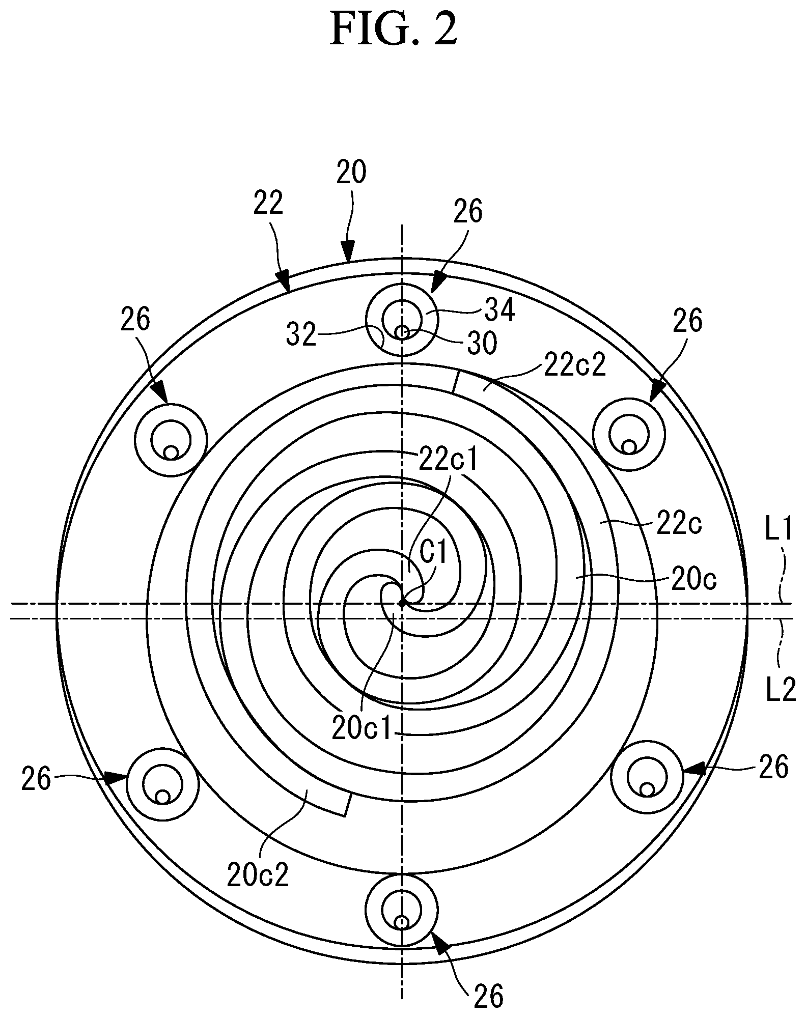
[0031] FIG. 2 is a transverse sectional view illustrating a scroll member of FIG. 1.
[0032] FIG. 3 is a plan view illustrating a pin-ring mechanism.
[0033] FIG. 4 is a partially enlarged longitudinal sectional view illustrating a periphery of the pin-ring mechanism.
[0034] FIG. 5 is a plan view illustrating a bush.
[0035] FIG. 6 is a plan view illustrating a contact state of the pin-ring mechanism.
[0036] FIG. 7 is a partially enlarged longitudinal sectional view illustrating a pin-ring mechanism of a co-rotating scroll compressor according to a second embodiment of the present invention.
[0037] FIG. 8 is a plan view illustrating the pin-ring mechanism of FIG. 7.
[0038] FIG. 9 is a partially enlarged longitudinal sectional view illustrating a periphery of a pin-ring mechanism of a co-rotating scroll compressor according to a third embodiment of the present invention.
[0039] FIG. 10A is a plan view illustrating a contact state of the pin-ring mechanism.
[0040] FIG. 10B is a plan view illustrating a contact state of the pin-ring mechanism, a phase of which advances by a predetermine angle with respect to FIG. 10A.
DESCRIPTION OF EMBODIMENTS
First Embodiment
[0041] Hereinafter, a first embodiment according to the present invention will be described with reference to the drawings.
[0042] FIG. 1 illustrates a longitudinal section of a scroll-type compressor 1. As illustrated in this figure, the scroll-type compressor 1 includes a driving part 3 and a compression mechanism part 5 in a housing 9.
[0043] The driving part 3 includes an electric motor 7 housed in a small-diameter part 9a of the housing 9. Radiating fins are provided on an outer periphery of the small-diameter part 9a of the housing 9. The electric motor 7 includes a stator 11 fixed to the housing 9 side, and a rotor 13 that rotates around a driving-side center axis L1 inside the stator 11. The rotor 13 is fixed to an outer periphery of a rotating shaft 15.
[0044] The rotating shaft 15 has both ends supported by bearings 17, 19. A shaft part 20a of a driving scroll member 20 is connected to the one end of the rotating shaft 15 (left end in FIG. 1). Therefore, the driving-side center axis L1 around which the rotating shaft 15 rotates and the driving-side center axis L1 around which the driving scroll member 20 rotates coincide with each other.
[0045] The compression mechanism part 5 is housed in a large-diameter part 9b of the housing 9, and includes a driving scroll member (first scroll member) 20 made of metal, and a driven scroll member (second scroll member) 22 made of metal.
[0046] Rotational driving force from the rotating shaft 15 is transmitted through the shaft part 20a, so that the driving scroll member 20 rotates around the driving-side center axis L1. The driving scroll member 20 includes a disk-shaped end plate (first end plate) 20b, and a spiral wall body (first wall body) 20c that is erected in the direction substantially perpendicular to the end plate 20b. As illustrated in FIG. 2, the spiral wall body 20c is in a spiral shape having a winding start part 20c1 on a central side, and having a winding end part 20c2 on an outer peripheral side. The shapes of an inner peripheral surface and an outer peripheral surface of the spiral wall body 20c are each formed by, for example, an involute curve. However, the winding start part 20c1 is formed by using various curves.
[0047] The driven scroll member 22 includes a disk-shaped end plate (second end plate) 22b, a spiral wall body (second wall body) 22c that is erected in the direction substantially perpendicular to the end plate 22b, and a shaft part 22a provided at the center of the end plate 22b.
[0048] Bearings 24 are mounted on an outer periphery of the shaft part 22a between the housing 9 and the outer periphery. Consequently, the driven scroll member 22 rotates around a driven-side center axis L2. The driving-side center axis L1 and the driven-side center axis L2 are offset by a predetermined distance p, and this predetermined distance p is a turning radius when the driving scroll member 20 and the driven scroll member 22 are in relative revolving motion.
[0049] The shaft part 22a is in a cylindrical shape, and compressed fluid (for example, air or a refrigerant) is discharged through a through hole 22a1 formed on a center side of the shaft part 22a.
[0050] As illustrated in FIG. 2, the spiral wall body 22c is in a spiral shape having a winding start part 22c1 on a central side, and having a winding end part 22c2 on an outer peripheral side. The shapes of an inner peripheral surface and an outer peripheral surface of the spiral wall body 22c are formed by, for example, an involute curve so as to engage with the spiral wall body 20c of the driving scroll member 20. However, a portion of the winding start part 22c1 is formed by using various curves.
[0051] Pin-ring mechanisms (synchronous driving mechanism) 26 that transmit power so as to synchronously rotate both the scroll members 20, 22 and to are in relative revolving motion are provided between the driving scroll member 20 and the driven scroll member 22. Herein, to rotate synchronously means to rotate in the same direction at the same angular velocity in the same phase.
[0052] As illustrated in FIG. 1, the pin-ring mechanisms 26 each include a pin member 30 fixed to the driven scroll member 22, and a ring member 34 fitted into a circular groove 32 formed in the end plate 20b of the driving scroll member 20.
[0053] Each pin member 30 is made of metal, and is fixed to an outer peripheral wall part 22d of the driven scroll member 22 facing the end plate 20b of the driving scroll member 20. The pin member 30 has a first end buried in the outer peripheral wall part 22d, and a second end provided so as to protrude to an inner peripheral side of the ring member 34.
[0054] Each circular groove 32 is a circular groove having an inner diameter corresponding to the outer diameter of the ring member 34, and is a hole that passes through the end plate 20b in this embodiment.
[0055] As illustrated in FIG. 3 and FIG. 4, the ring member 34 is a ball bearing (rolling bearing), and includes an outer ring 34a disposed such that an outer periphery is in contact with the circular groove 32, an inner ring 34b disposed such that an inner peripheral side is in contact with the pin member 30, a plurality of balls (rolling bodies) 34c disposed between the outer ring 34a and the inner ring 34b, and a retainer 34d that holds respective relative positions of the balls 34c.
[0056] On the inner peripheral side of the inner ring 34b, a bush (intermediate member) 36 made of resin is fitted. As illustrated in FIG. 5, the bush 36 is in a substantial disk shape. A cutout 36a cut out from the outer peripheral side toward the center side is formed in one part of the bush 36. The cutout 36a is formed such that the opening width is increased toward the outer peripheral side.
[0057] As illustrated in FIG. 2, six combinations of the pin member 30, the circular groove 32 and the ring member 34 are provided around a center C1 of the driving scroll member 20. The number of the combinations of the pin member 30, the circular groove 32, and the ring member 34 are six in this embodiment, but only needs to be three or more, for example, may be four.
[0058] FIG. 6 illustrates a state in which power is transmitted by the six pin-ring mechanisms 26. In this figure, the power is transmitted through the pin member 30 by the pin-ring mechanism 26-1 located at a left end. That is, an outer peripheral surface of the pin member 30 of the pin-ring mechanism 26-1 comes into contact with an inner peripheral surface of the inner ring 34b, and power transmission with the end plate 20b is achieved through the balls 34c and the outer ring 34a.
[0059] On the other hand, the power is not transmitted by the five pin-ring mechanisms 26 other than the pin-ring mechanism 26-1. However, the pin member 30 and the bush 36 are normally in contact with each other even when the pin member 30 and the inner ring 34b are not in direct contact with each other. That is, a side surface forming the cutout 36a of the bush 36 is in contact with the outer peripheral surface of the pin member 30. Consequently, a component of force in the circumferential direction of the inner ring 34b is applied from the pin member 30, and the bush 36 rotates together with the inner ring 34b. The inner ring 34b rotates, so that all the balls 34c roll. That is, even when the pin-ring mechanism 26 does not contribute to the power transmission with the pin member 30, all the balls 34c roll.
[0060] The scroll-type compressor 1 having the aforementioned configuration operates as follows.
[0061] The electric motor 7 is driven by power supplied from a power source (not illustrated), and the rotor 13 rotates, so that the rotating shaft 15 rotates around the driving-side center axis L1. Rotational driving force of the rotating shaft 15 is transmitted to the driving scroll member 20 through the shaft part 20a, and the driving scroll member 20 rotates around the driving-side center axis L1. Rotating force of the driving scroll member 20 is transmitted to the driven scroll member 22 by the pin-ring mechanisms 26. At this time, the pin members 30 of the pin-ring mechanisms 26 rotate in contact with inner peripheries of the ring members 34 along the inner peripheries, so that the driving scroll member 20 and the driven scroll member 22 are in relative revolving motion.
[0062] The driving scroll member 20 and the driven scroll member 22 are in relative revolving motion, so that a compression space formed between the spiral wall body 20c of the driving scroll member 20, and the spiral wall body 22c of the driven scroll member 22 is reduced in accordance with movement from the outer peripheral side to the center side, and fluid sucked from the outer peripheral sides of the scroll members 20, 22 is compressed. The compressed fluid is discharged from the through hole 22a1 formed in the shaft part 22a of the driven scroll member 22 to the outside.
[0063] According to this embodiment, the following action effects are exhibited.
[0064] The bush 36 disposed on the inner periphery of the inner ring 34b of each pin-ring mechanism 26 is provided. The bush 36 receives a component of force in the circumferential direction of the inner ring 34b from the pin member 30, and rotates together with the inner ring 34b. The bush 36 rotates the inner ring 34b, so that the balls 34c can be rolled. Consequently, it is possible to avoid a state in which only the ball 34c corresponding to such a position that the pin member 30 and the inner ring 34b come into contact with each other rolls, and other balls 34c each tend to be kept in a stationary state. Therefore, it is possible to reduce a load to be applied to the retainer 34d holding the balls 34c, and it is possible to avoid damage on the retainer 34d.
[0065] The bush 36 is in the substantial disk shape formed so as to come in contact with the inner periphery of the inner ring 34b, so that a load to be transmitted between the pin member 30 and the inner ring 34b can be smoothly transmitted to the inner ring 34b. Additionally, the bush 36 is provided with the cutout 36a having a clearance between the pin member 30 and the bush 36 at a position corresponding to the pin member 30, and therefore the bush 36 does not need to restrain movement of the pin member 30 more than necessary, and can effectively exert a function as a synchronous driving mechanism.
Second Embodiment
[0066] Now, a co-rotating scroll compressor according to a second embodiment of the present invention will be described. This embodiment is different from the first embodiment in a pin-ring mechanism, but is similar in others. Therefore, the pin-ring mechanism will be described in the following description.
[0067] As illustrated in FIG. 7 and FIG. 8, a pin-ring mechanisms 26' includes an O-ring (an intermediate member, an elastic member) 38 provided on an outer periphery of a pin member 30. In this embodiment, the bush 36 described in the first embodiment is not provided.
[0068] The O-ring 38 is provided so as to protrude outward with respect to an outer peripheral surface of the pin member 30 in an unloaded state. Consequently, even in the unloaded state, the O-ring 38 is always in contact with an inner periphery of the inner ring 34b, and rotates the inner ring 34b.
[0069] As illustrated in FIG. 8, when power is transmitted between the pin member 30 and the inner ring 34b, the O-ring 38 is squeezed, so that the power is transmitted. At this time, the outer diameter of the O-ring 38 is preferably determined such that the inner ring 34b and the pin member 30 are not in direct contact with each other. This is to avoid contact between metal members to reduce noise.
[0070] As illustrated in FIG. 7, the O-ring 38 is disposed at an intermediate position of the height H in the axial direction (vertical direction in this figure) of the inner ring 34b. Consequently, a posture of the inner ring 34b can be prevented from inclining to the axial direction when power is transmitted to the inner ring 34b.
Third Embodiment
[0071] Now, a co-rotating scroll compressor according to a third embodiment of the present invention will be described. This embodiment is different from each of the aforementioned embodiments in a fixing structure of a pin of a pin-ring mechanism. However, this embodiment is similar in others, and therefore the pin-ring mechanism will be described in the following description.
[0072] As illustrated in FIG. 9, a pin member 30 is made of metal, and is fixed to an outer peripheral wall part 22d of a driven scroll member 22 facing an end plate 20b of a driving scroll member 20. A first end of the pin member 30 is fixed to the outer peripheral wall part 22d of the driven scroll member 22 through ball bearings (rolling bearings) 37 so as to be freely rotate around an axis. In this way, the pin member 30 is rotatably supported by the ball bearings 37, the pin member 30 rolls without generating large friction even when the pin member 30 comes into contact with a side wall forming a cutout 36a of a bush 36.
[0073] In this embodiment, the number of the ball bearings 37 is two, but may be one, or three or more. A second end of the pin member 30 is provided so as to protrude on an inner peripheral side of a ring member 34.
[0074] The ball bearings 37 are used as bearings that rotatably support the pin member 30. However, other rolling bearing may be used, and for example, a needle bearing (needle roller bearing) may be used.
[0075] According to this embodiment, the following action effects are exhibited.
[0076] The ball bearings 37 that support the pin member 30 rotatably around the axis are provided. Consequently, when the pin member 30 comes into contact with the bush 36, the pin member 30 rotates around the axis, and therefore wear due to friction between the pin member 30 and the bush 36 is reduced, and it is possible to increase the life of the pin-ring mechanism 26.
[0077] The bush 36 is made of resin, and therefore when the bush 36 comes into contact with the pin member 30 made of metal, large wear may be caused in the bush 36. On the other hand, the pin member 30 is supported by the ball bearings 37 to be freely rotate, and therefore it is possible to reduce the wear of the bush 36.
[0078] In each of the aforementioned embodiments, the pin member 30 of the pin-ring mechanism 26, 26' is provided in the driven scroll member 22, and the ring member 34 is provided in the driving scroll member 20. However, the pin member 30 may be provided in the driving scroll member 20, and the ring member 34 may be provided in the driven scroll member 22, or the members may be divided into the scroll members 20, 22.
[0079] The shape of the cutout 36a formed in the bush 36 of each of the first embodiment and the third embodiment is not limited to these embodiments, any shape that allows contact with the outer peripheral surface of the pin member 30 even in a case of an unloaded state may be employed.
[0080] Not only a co-rotating scroll compressor 1 in each embodiment, but also a fixed and turning type scroll-type compressor in which one scroll member is a fixed scroll, and the other scroll member is a turning scroll can be applied.
REFERENCE SIGNS LIST
[0081] 1 scroll-type compressor [0082] 3 driving part [0083] 5 compression mechanism part [0084] 7 electric motor [0085] 9 housing [0086] 11 stator [0087] 13 rotor [0088] 15 rotating shaft [0089] 17 bearing [0090] 19 bearing [0091] 20 driving scroll member (first scroll member) [0092] 20a shaft part [0093] 20b end plate (first end plate) [0094] 20c spiral wall body (first wall body) [0095] 20c1 winding start part [0096] 20c2 winding end part [0097] 22 driven scroll member (second scroll member) [0098] 22a shaft part [0099] 22b end plate (second end plate) [0100] 22c spiral wall body (second wall body) [0101] 22c1 winding start part [0102] 22c2 winding end part [0103] 24 bearing [0104] 26, 26' pin-ring mechanism (synchronous driving mechanism) [0105] 30 pin member [0106] 32 circular groove [0107] 34 ring member [0108] 34a outer ring [0109] 34b inner ring [0110] 34c ball (rolling body) [0111] 34d retainer [0112] 36 bush (intermediate member) [0113] 36a cutout [0114] 37 ball bearing (rolling bearing) [0115] 38 O-ring (intermediate member, elastic member) [0116] L1 driving-side center axis [0117] L2 driven-side center axis
* * * * *
D00000
D00001
D00002
D00003
D00004
D00005
D00006
D00007
XML
uspto.report is an independent third-party trademark research tool that is not affiliated, endorsed, or sponsored by the United States Patent and Trademark Office (USPTO) or any other governmental organization. The information provided by uspto.report is based on publicly available data at the time of writing and is intended for informational purposes only.
While we strive to provide accurate and up-to-date information, we do not guarantee the accuracy, completeness, reliability, or suitability of the information displayed on this site. The use of this site is at your own risk. Any reliance you place on such information is therefore strictly at your own risk.
All official trademark data, including owner information, should be verified by visiting the official USPTO website at www.uspto.gov. This site is not intended to replace professional legal advice and should not be used as a substitute for consulting with a legal professional who is knowledgeable about trademark law.