System And Method For Modeling A Transient Fluid Level Of A Well
MADASU; Srinath ; et al.
U.S. patent application number 16/336814 was filed with the patent office on 2020-01-16 for system and method for modeling a transient fluid level of a well. The applicant listed for this patent is Halliburton Energy Services, Inc.. Invention is credited to Avi LIN, Srinath MADASU, Yijie SHEN.
| Application Number | 20200018153 16/336814 |
| Document ID | / |
| Family ID | 62110319 |
| Filed Date | 2020-01-16 |


View All Diagrams
| United States Patent Application | 20200018153 |
| Kind Code | A1 |
| MADASU; Srinath ; et al. | January 16, 2020 |
SYSTEM AND METHOD FOR MODELING A TRANSIENT FLUID LEVEL OF A WELL
Abstract
The disclosed embodiments include a method for determining fluid level drop and formation permeability during wellbore stimulation of a shut-in stage in real time. The method includes receiving an initial permeability value of a formation surrounding a wellbore. Further, the method includes performing, and if necessary repeating at a defined time interval, the following steps until a flowrate of stimulation fluid reaches zero or until a new pumping stage begins. The steps include solving for the flowrate of the stimulation fluid in the wellbore and computing hydrostatic pressure and a computed temperature in the wellbore. Further, the steps include updating a permeability calculation of the formation based on the flowrate of the stimulation fluid.
| Inventors: | MADASU; Srinath; (Houston, TX) ; LIN; Avi; (Houston, TX) ; SHEN; Yijie; (Houston, TX) | ||||||||||
| Applicant: |
|
||||||||||
|---|---|---|---|---|---|---|---|---|---|---|---|
| Family ID: | 62110319 | ||||||||||
| Appl. No.: | 16/336814 | ||||||||||
| Filed: | November 9, 2016 | ||||||||||
| PCT Filed: | November 9, 2016 | ||||||||||
| PCT NO: | PCT/US2016/061154 | ||||||||||
| 371 Date: | March 26, 2019 |
| Current U.S. Class: | 1/1 |
| Current CPC Class: | E21B 49/087 20130101; E21B 47/07 20200501; C09K 8/60 20130101; E21B 47/103 20200501; E21B 43/26 20130101 |
| International Class: | E21B 47/10 20060101 E21B047/10; E21B 47/06 20060101 E21B047/06; E21B 49/08 20060101 E21B049/08; E21B 43/26 20060101 E21B043/26 |
Claims
1. A method for determining fluid level drop and formation permeability during wellbore stimulation of a shut-in stage in real time, comprising: receiving an initial permeability value of a formation surrounding a wellbore; and performing, and if necessary repeating at a defined time interval, the following steps until a flowrate of stimulation fluid reaches zero or until a new pumping stage begins: solving for the flowrate of the stimulation fluid in the wellbore; computing hydrostatic pressure and a computed temperature in the wellbore; and updating a permeability calculation of the formation based on the flowrate of the stimulation fluid.
2. The method of claim 1, comprising: receiving a measured temperature from a distributed temperature sensing (DTS) system; and updating the flowrate based on a comparison of the computed temperature and the measured temperature when an accuracy of the flowrate is not acceptable.
3. The method of claim 2, wherein updating the flowrate when the accuracy of the flowrate is not acceptable comprises: determining whether the computed temperature is greater than the measured temperature; when the computed temperature is greater than the measured temperature, doubling the flowrate; and when the computed temperature is less than the measured temperature, dividing the flowrate by 1.75.
4. The method of claim 2, comprising: determining whether the accuracy of the flowrate is acceptable, wherein determining whether the accuracy of the flowrate is acceptable comprises: determining whether a difference between the computed temperature and the measured temperature exceeds a tolerance value.
5. The method of claim 1, comprising: computing a fluid level drop within the wellbore based on the flowrate; and updating stimulation fluid presence in divisions of the wellbore based on the fluid level drop.
6. The method of claim 1, wherein the permeability calculation of the formation is determined based on Darcy's law.
7. The method of claim 1, wherein solving for the flowrate of the stimulation fluid in the wellbore comprises: calculating an individual flow rate of each division of the wellbore; and adding together the individual flow rates of each division of the wellbore.
8. The method of claim 1, wherein the initial permeability value of the formation is based on logs produced from core samples of the formation.
9. The method of claim 1, wherein the stimulation fluid comprises fracturing fluid or acidizing fluid.
10. The method of claim 1, wherein the defined time steps comprise one second increments of time.
11. A system for determining formation permeability during wellbore stimulation, comprising: a distributed temperature sensing (DTS) system comprising a fiber optic cable extending a length of a wellbore, wherein the DTS system is configured to provide a real-time measurement of a measured temperature of the wellbore; a controller communicatively coupled to the DTS system, the controller comprising a processor and a memory, wherein the memory comprises instructions, that when executed, cause the processor to: receive an initial permeability value of a formation surrounding the wellbore; and perform, and if necessary repeat at a defined time interval, the following instructions until a flowrate of stimulation fluid reaches zero or until a new pumping stage begins: solve for the flowrate of the stimulation fluid in the wellbore; compute hydrostatic pressure and computed temperature in the wellbore; compare the computed temperature to the measured temperature to determine accuracy of the flowrate; update the flowrate when the accuracy of the flowrate is not acceptable; and update a permeability calculation of the formation based on the flowrate of the stimulation fluid.
12. The system of claim 11, wherein the stimulation fluid comprises acidizing fluid or fracturing fluid.
13. The system of claim 11, wherein the initial permeability value of the formation is based on logs produced from core samples of the formation.
14. The system of claim 11, wherein determining the accuracy of the flowrate comprises: determining whether a difference between the computed temperature and the measured temperature exceeds a tolerance value.
15. The system of claim 11, wherein the instructions that cause the processor to solve for the flowrate of the stimulation fluid in the wellbore comprise instructions that cause the processor to: calculate an individual flow rate of each division of the wellbore; and add together the individual flow rates of each division of the wellbore.
16. The system of claim 11, wherein the instructions that cause the processor to update the flowrate when the accuracy of the flowrate is not acceptable comprise instructions that cause the processor to: determine whether the computed temperature is greater than the measured temperature; when the computed temperature is greater than the measured temperature, double the flowrate; and when the computed temperature is less than the measured temperature, divide the flowrate by 1.75.
17. A non-transitory machine-readable medium comprising instructions stored therein, which when executed by one or more processors, causes the one or more processors to perform operations comprising: receiving an initial permeability value of a formation surrounding a wellbore; and performing, and if necessary repeating at a defined time interval, the following operations until a flowrate of stimulation fluid reaches zero or until a new pumping stage begins: solving for the flowrate of the stimulation fluid in the wellbore; computing hydrostatic pressure and computed temperature in the wellbore; receiving a measured temperature of the wellbore; comparing the computed temperature to the measured temperature to determine accuracy of the flowrate; updating the flowrate when the accuracy of the flowrate is not acceptable; and updating a permeability calculation of the formation based on the flowrate of the stimulation fluid.
18. The medium of claim 17, wherein receiving the measured temperature of the wellbore comprises receiving the measured temperature in real-time from a distributed temperature sensing (DTS) system.
19. The medium of claim 17, wherein updating the flowrate when the accuracy of the flowrate is not acceptable comprises: determining whether the computed temperature is greater than the measured temperature; when the computed temperature is greater than the measured temperature, doubling the flowrate; and when the computed temperature is less than the measured temperature, dividing the flowrate by 1.75.
20. The medium of claim 17, comprising recording the permeability calculation in a memory at each time step.
Description
BACKGROUND
[0001] The present disclosure relates generally to formation characteristic measurements of formations surrounding a wellbore, and, more specifically, to systems and methods for modeling dynamics of flow distribution along a simulated wellbore during a shut-in process.
[0002] During a shut-in stage of a stimulation process (e.g., fracturing or acidizing a formation), no fluids are inserted into the wellbore at the top of the wellhead. Accordingly, fluid flow within the wellbore is driven by a difference between wellbore pressure and reservoir pressure. Because pressure in the wellbore is often greater than or less than the reservoir pressure, a level of the fluids within the wellbore during the shut-in stage dynamically changes based on wellbore and reservoir conditions. While the level of fluids within the wellbore during the shut-in stage changes dynamically, traditional measurements of fluid level within the wellbore only provide static measurement opportunities. That is, the traditional measurements of the fluid level may only be available during the shut-in stage after an equilibrium is reached between the wellbore and reservoir pressures. Such measurements do not consider time varying fluid level drop. Additionally, the traditional measurements do not overcome a no-flow assumption to the reservoir pressure and fluid level computation. For example, the traditional measurements fail to account for leakage flow of stimulation fluids from the wellbore to the reservoir, which results in dynamic decreases in pressure and fluid level within the wellbore.
BRIEF DESCRIPTION OF THE DRAWINGS
[0003] Illustrative embodiments of the present disclosure are described in detail below with reference to the attached drawing figures, which are incorporated by reference herein, and wherein:
[0004] FIG. 1A is a schematic illustration of a side view of a well fracturing environment;
[0005] FIG. 1B is a schematic illustration of a side view of a well acidizing environment;
[0006] FIG. 2 is a schematic illustration of a wellbore during a shut-in stage including an indication of a flow of stimulation fluid from the wellbore to a formation;
[0007] FIG. 3 is a schematic illustration of a wellbore during the shut-in stage at equilibrium and the wellbore during a subsequent pumping stage;
[0008] FIG. 4 is a flow chart of a method for iteratively calculating well conditions during a shut-in stage of a well;
[0009] FIG. 5 is a graph of bottom-hole pressure of a wellbore over time during a shut-in stage and a pumping stage of a well;
[0010] FIG. 6 is a graph of bottom-hole temperature of a wellbore over time during a shut-in stage and a pumping stage of a well; and
[0011] FIG. 7 is a flow chart of a method for updating calculations of permeability of a formation during a shut-in stage of a well.
[0012] The illustrated figures are only exemplary and are not intended to assert or imply any limitation with regard to the environment, architecture, design, or process in which different embodiments may be implemented.
DETAILED DESCRIPTION
[0013] In the following detailed description of the illustrative embodiments, reference is made to the accompanying drawings that form a part hereof. These embodiments are described in sufficient detail to enable those skilled in the art to practice the invention, and it is understood that other embodiments may be utilized and that logical structural, mechanical, electrical, and chemical changes may be made without departing from the spirit or scope of the invention. To avoid detail not necessary to enable those skilled in the art to practice the embodiments described herein, the description may omit certain information known to those skilled in the art. The following detailed description is, therefore, not to be taken in a limiting sense, and the scope of the illustrative embodiments is defined only by the appended claims.
[0014] As used herein, the singular forms "a", "an" and "the" are intended to include the plural forms as well, unless the context clearly indicates otherwise. It will be further understood that the terms "comprise" and/or "comprising," when used in this specification and/or the claims, specify the presence of stated features, steps, operations, elements, and/or components, but do not preclude the presence or addition of one or more other features, steps, operations, elements, components, and/or groups thereof. In addition, the steps and components described in the above embodiments and figures are merely illustrative and do not imply that any particular step or component is a requirement of a claimed embodiment.
[0015] Unless otherwise specified, any use of any form of the terms "connect," "engage," "couple," "attach," or any other term describing an interaction between elements is not meant to limit the interaction to direct interaction between the elements and may also include indirect interaction between the elements described. In the following discussion and in the claims, the terms "including" and "comprising" are used in an open-ended fashion, and thus should be interpreted to mean "including, but not limited to". Unless otherwise indicated, as used throughout this document, "or" does not require mutual exclusivity.
[0016] The present disclosure relates to measuring formation characteristics of a formation surrounding a wellbore. More particularly, the present disclosure relates to systems and methods for dynamically measuring conditions of a formation surrounding a wellbore during a shut-in stage of a stimulation process. The presently disclosed embodiments may be applicable to horizontal, vertical, deviated, or otherwise nonlinear wellbores in any type of subterranean formation. Embodiments may be implemented in the shut-in stage of stimulation processes, such as an acidizing process or a fracturing process. Further, the embodiments may be implemented using a distributed temperature sensing (DTS) system to provide real-time temperature feedback from within the wellbore to a model that models the formation characteristics.
[0017] Referring to FIG. 1A, a schematic illustration of a side view of a well fracturing environment 100 including a well 102. In the embodiment of FIG. 1, a rig 104 is positioned at a surface 106 of the well 102. The well 102 includes a wellbore 108 that extends from the surface 106 to a subterranean formation 110. A derrick 112 is positioned above the well 102, and the derrick 112 may be used during formation of the well 102 to support boring equipment and to hoist and lower pipe into the wellbore 108, among other tasks. Also depicted is a wellhead 113, which may be used during a shut-in process to seal the wellbore 108.
[0018] Fractures 114 are illustrated within the formation 110. In an embodiment, the fractures 114 are produced in the formation by pumping fracturing fluid into the wellbore 108 at a high pressure using a pump 116 and a fracturing fluid tank 118. The pump 116 provides the fracturing fluid from the fracturing fluid tank 118 to the wellbore 108 at a pressure greater than a fracturing pressure of the formation 110. That is, the fracturing fluid is provided to the wellbore 108 at a pressure greater than a pressure that results in the formation 110 fracturing hydraulically. For example, the fracturing pressure of the formation 110 may be in the range of 6500 to 10,000 psi.
[0019] In an embodiment, the well fracturing environment 100 also includes a controller 120 that includes a memory 122 and at least one processor 124. The controller 120 may be used to dynamically model characteristics of the formation 110, such as porosity and permeability. The memory 122 may store instructions related to the dynamic model of the controller 120, and the memory 122 may also store data used by the controller 120 to dynamically model the characteristics of the formation 110. In an embodiment, the processor 124 executes the instructions of the memory to perform the dynamic modeling. The instructions stored in the memory 122 and executed by the processor 124 may include, but are not limited to, machine code instructions, bytecode for a software interpreter, object code, and source code in a high-level programming language. The controller 120 may also receive inputs from input devices, such as a keyboard, a mouse, and a touchscreen, and the controller 120 may also output information to an output device, such as a monitor.
[0020] In various embodiments, the at least one processor 124 may be a single-processor system or a multi-processor system including two or more processors 124 (e.g., two, four, eight, or another suitable number). The processor 124 may be any processor capable of executing program instructions. For example, in various embodiments, the processor 124 may be a general-purpose processor or an embedded processor implementing any of a variety of instruction set architectures. Further, the memory 122 may store program instructions, data, or a combination thereof that are accessible by the processor 124. In an embodiment, the memory 122 may be implemented using any suitable memory technology, such as static random access memory (SRAM), nonvolatile memory, or any other type of memory. In other embodiments, program instructions, data, or both may be received, sent, or stored in different types of computer-accessible media or on similar media separate from the memory 122 or the controller 120.
[0021] A computer-accessible medium may include any tangible or non-transitory storage media or memory media such as electronic, magnetic, or optical media coupled to the controller 120. The terms "tangible" and "non-transitory," as used herein, are intended to describe a computer-readable storage medium excluding propagating electromagnetic signals, but the terms are not intended to otherwise limit the type of physical computer-readable storage device that is encompassed by the phrase computer-readable medium or memory. For instance, the terms "non-transitory computer-readable medium" or "tangible memory" are intended to encompass types of storage devices that do not necessarily store information permanently, including, for example, random access memory (RAM). Program instructions and data stored on a tangible computer-accessible storage medium in non-transitory form may further be transmitted by transmission media or signals such as electrical, electromagnetic, or digital signals, which may be conveyed via a communication medium such as a network or wireless link.
[0022] To enhance accuracy of the dynamic model of the formation characteristics calculated by the controller 120, a distributed temperature sensing (DTS) system may be provided at the well 102, and the DTS system includes an optical cable 126 that is coupled to the controller 120 and extends the length of the wellbore 108. The optical cable 126 and the DTS system may provide real-time temperature measurements along the length of the wellbore 108 to the controller 120. For example, as temperature within the wellbore 108 changes, the temperature change can affect transmission of light through the optical cable 126. Accordingly, temperature measurements may be determined at any point along the optical cable 126 by detecting changes in the transmission of light through the optical cable 126 resulting from the change in temperature. By providing real-time temperature measurements to the controller 120, an accuracy of the dynamic model may be checked and compensated for appropriately, as discussed in detail below with reference to FIG. 7.
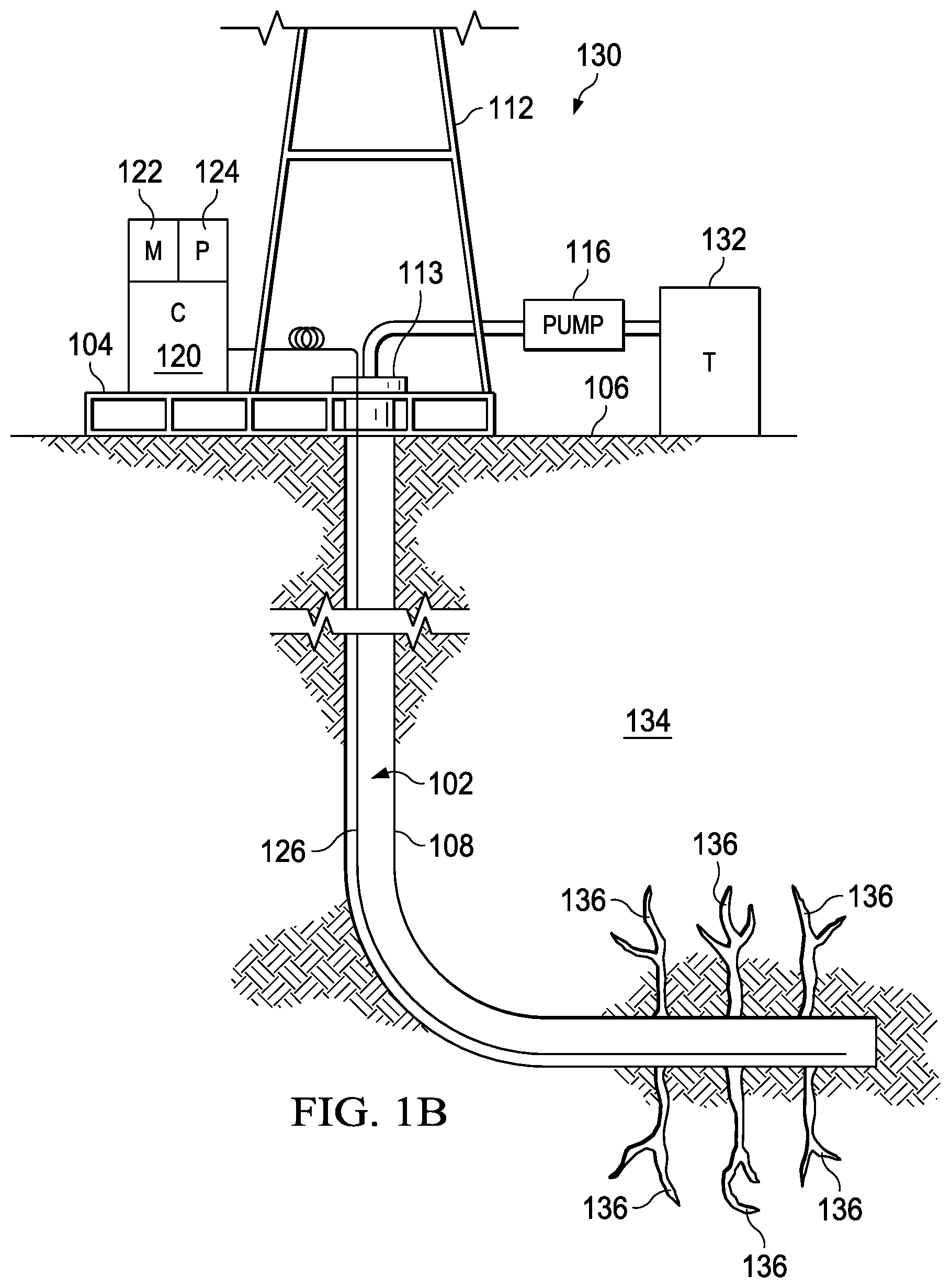
[0023] FIG. 1B is a schematic illustration of a side view of a well acidizing environment 130 within the wellbore 108. The well acidizing environment 130 is similar to the well fracturing environment 100 except that the stimulation element is a lower pressure acidizing fluid, as opposed to the high pressure fracturing fluid that is provided to the wellbore 108 with reference to FIG. 1A. The pump 116 pumps acidizing fluid into the wellbore 108 from an acidizing fluid tank 132.
[0024] In an embodiment, acidizing fluid is used in a formation stimulation process when a formation 134 has a greater permeability than the formation 110, which is better suited for a fracturing process. Using the acidizing fluid, wormholes 136 are produced in the formation 134 instead of the fractures 114 produced using a fracturing process. The wormholes 136 result from the acidizing fluid interacting with the formation 134 to dissolve formation materials to produce new passageways or to expand existing passageways for formation fluids to flow. In some embodiments, the acidizing fluid may include a hydrochloric acid (HCl) base that dissolves carbonate based materials within the formation 134. In other embodiments, such as in sandstone formations, hydrofluoric acid (HF) may be used in combination with HCl as the base of the acidizing fluid. Additionally, in some embodiments, the acidizing fluid is provided at a pressure greater than the fracturing pressure of the formation 134. In such an embodiment, the acidizing fluid may produce both the fractures 114 and the wormholes 136 within the formation 134.
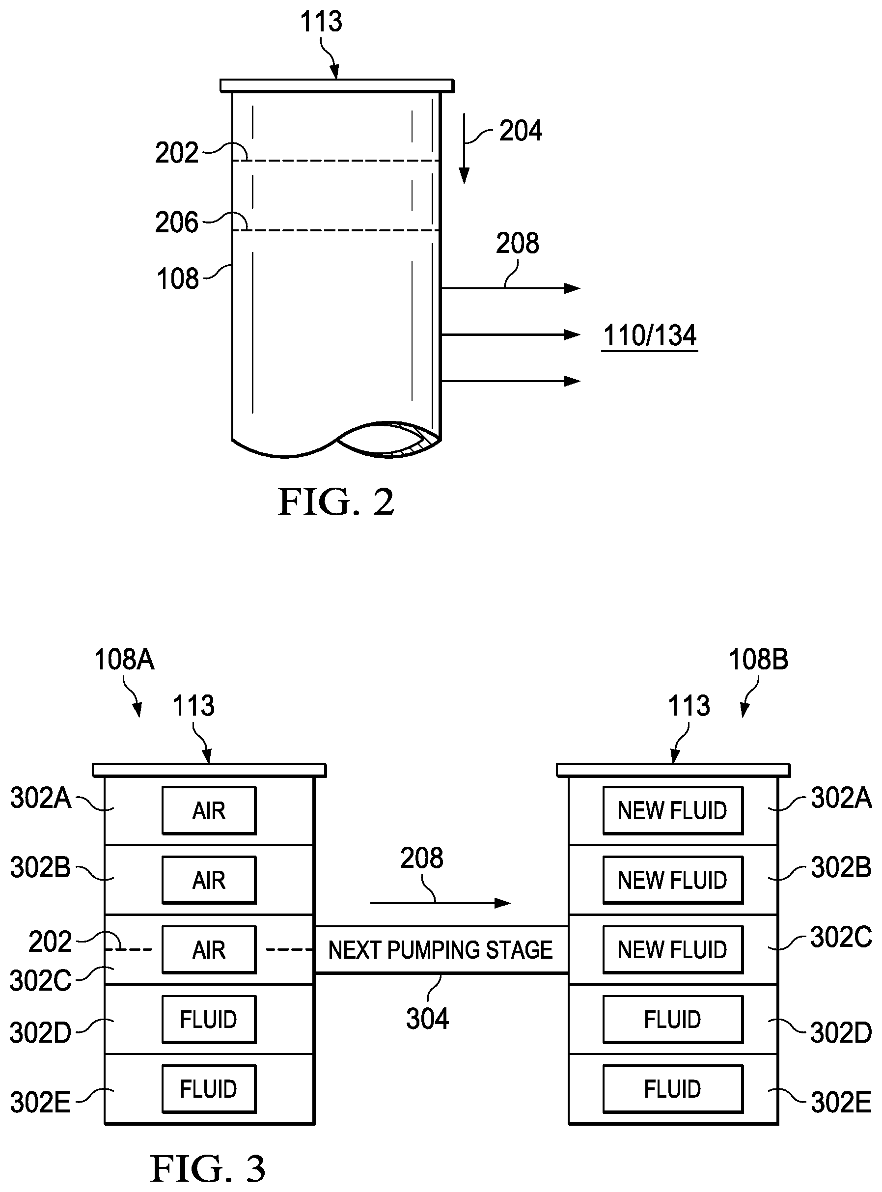
[0025] FIG. 2 is a schematic illustration of the wellbore 108 during a shut-in stage including an indication of a flow of stimulation fluid (e.g., fracturing fluid or acidizing fluid) from the wellbore 108 to the formation 110/134. During the shut-in stage, pumping of the stimulation fluid at the wellhead 113 ceases, and a fluid level 202 is established at the onset of the shut-in stage. Because the stimulation fluid is no longer provided to the wellbore 108, flow of the stimulation fluids is established by a difference between hydrostatic pressure within the wellbore 108 and reservoir pressure of the formation 110/134. As illustrated, the reservoir pressure of the formation 110/134 is less than the hydrostatic pressure within the wellbore 108. Accordingly, the stimulation fluid within the wellbore 108 travels in a direction 204 in the wellbore 108 to establish a new fluid level 206. The new fluid level 206 is the result of leak-off 208 of the stimulation fluid in the wellbore 108 to the formation 110/134. In another embodiment, the reservoir pressure may be greater than the hydrostatic pressure within the wellbore 108. In such an embodiment, the reservoir fluids may travel from the formation into the wellbore 108, which results in the fluid level 202 moving toward the wellhead 113.
[0026] Because the flow of fluids from or to the wellbore 108 is transient, the model used to determine characteristics of the formation may be dynamically altered as the shut-in stage progresses. Using the model, a pressure, fluid velocity, and temperature variation along the stimulated wellbore 108 predicts flow loss or gain of fluid to the formation 110/134. The effects of the flow of the fluids within the wellbore 108 and temperature distributions along the wellbore 108 during the shut-in stage enable an accurate design and analysis of the well production systems of a reservoir to effectively compute fluid flow or fluid and proppant flow during production of formation fluids from the well 102.
[0027] During the shut-in stage, the fluid level 202 within the wellbore 208 continuously drops or increases to a point where the hydrostatic pressure of the fluid within the wellbore 208 and the temperature within the wellbore 208 equilibrate with the reservoir pressure and temperature of the formation 110/134. The increase or decrease in the hydrostatic pressure of the fluid within the wellbore 208 is due to an increase or decrease in the fluid level 202 during the equilibration process. To help illustrate, a net flow rate in the wellbore 108 is given by the following equation:
q . w = i = 1 ndivisions q i , ( Equation 1 ) ##EQU00001##
where {dot over (q)}.sub.w is the net flow rate of the wellbore 108, ndivisions is a number of divisions within the wellbore 108, and q.sub.i is an individual flow rate at a division of the wellbore 108. The individual divisions (e.g., grid blocks) may be evenly spaced sections of the wellbore 108. For example, each division may represent the average conditions of one foot of length of the wellbore 108 at a specific location within the wellbore 108. The size and number of divisions within a simulated wellbore may vary. For example, each division could be larger or smaller than one foot depending on a desired accuracy of the net flow rate in the wellbore 108. The individual flow rate in each division is given by Darcy's Law, but Darcy's law is applied over the entire reservoir (e.g., formation 110/134) and includes measurements of the different fluids found within the reservoir. Accordingly, the following equation provides a volumetric flow rate for any number of fluids combining the Darcy flow with a hydrostatic pressure variation:
q . i = 2 .pi. ( .rho. i g ( X i - L S ) - P reservoir ) j = 1 nfronts ln ( r endj r frontj ) k j .mu. j , ( Equation 2 ) ##EQU00002##
where {dot over (q)}.sub.i is the individual flow rate at a division i, .rho..sub.i is a density of the fluid within the wellbore 108 at the division i, g is the gravitational constant, X.sub.i is a change in liquid level at the division i, L.sub.s is a liquid level within the wellbore 108, P.sub.reservoir is the reservoir pressure, nfronts is a number of fluid fronts within the wellbore 108 where the fluid fronts are interfaces between fluids, r.sub.endj is a radius of the wellbore 108 at a deepest point of an individual fluid front, r.sub.frontj is a radius of the wellbore 108 at a shallowest point of the individual fluid front, k.sub.j is a permeability of the formation 110/134 at the individual fluid front, and .mu..sub.j is a viscosity of the fluid at the individual fluid front. The gravitational constant g, the reservoir pressure P.sub.reservoir, and the initial permeability k.sub.j are known values. Further, density .rho..sub.i and viscosity .mu..sub.j are determined from equations 9 and 10, respectively, which are provided below. Furthermore, the number of fluid fronts nfronts are estimated.
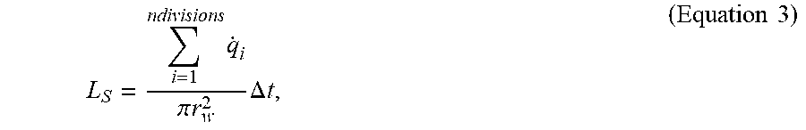
[0028] Further, assuming small increments in time, the liquid level within the wellbore 108 with respect to time, L.sub.s(t), is provided by the following equation:
L S = i = 1 ndivisions q . i .pi. r w 2 .DELTA. t , ( Equation 3 ) ##EQU00003##
where r.sub.w is a radius of the wellbore 108. Using equation 3, an accurate model of the liquid level within the wellbore 108 at any time step during the shut-in stage is available. A change in the liquid level at each time step also provides an indication of the fluid flow rate to or from the formation 110/134.
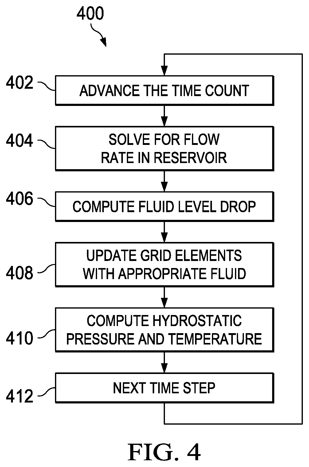
[0029] Referring to FIG. 3, a schematic illustration of a wellbore 108A during the shut-in stage at equilibrium and a wellbore 108B during a subsequent pumping stage is depicted. The wellbores 108A and 108B include divisions 302A-302E (e.g., grid elements). The divisions 302A-302E represent equal portions of the wellbore 108. Calculations related to the individual divisions 302A-302E may represent each of the divisions 302A-302E as a whole. For example, when the divisions 302A-302E each represent one foot of the wellbore 108, individual calculations related to the divisions 302A-302E represent the characteristics of each of the divisions 302A-302E as a sampling point along the length of the wellbore 108.
[0030] As illustrated, the wellbore 108A includes divisions 302A-302C filled with air, while divisions 302D and 302E contain fluid. Because the wellbore 108A is at equilibrium with the formation 110/134, the fluid level 202 moved away from the wellhead 113 due to the leakoff 208 of the stimulating fluid into the formation 110/134. In an embodiment, the leakoff 208 results from the hydrostatic pressure of the wellbore 108 being greater than the reservoir pressure of the formation 110/134. As the fluid level 202 moves away from the wellhead 113, the divisions 302A-302C fill with air.
[0031] At block 304, the wellbore 108 moves to a subsequent pumping stage. As shown in the wellbore 108B, new stimulating fluid is pumped into the wellbore 108B from the wellhead 113 to fill the air space in divisions 302A-302C with the new stimulating fluid. The wellbore 108B may then enter an additional shut-in stage, and characteristics of the wellbore 108B may be measured as the stimulating fluid in the wellbore 108B moves again to equilibrium. Characteristics of the fluid within the wellbore 108 may also be tracked. For example, fluid temperature in the wellbore 108 is constantly changing until the fluid temperature attains equilibrium with a temperature of the surrounding formation 110/134. Assuming a steady state and incompressible fluid, the temperature of the divisions 302A-302E in the wellbore 108 is provided by the following equation:
T well = T earth + Ag sin .theta. + ( ( T fbh - T earth ) - Ag sin .theta. ) exp ( L bh - .eta. ) A , ( Equation 4 ) ##EQU00004##
where T.sub.well is the temperature in the wellbore 108, T.sub.earth is the temperature of the surrounding formation 110/134, g is gravity, .theta. is an angle of the well with respect to the horizontal axis, T.sub.fbh is a bottom-hole temperature of the wellbore 108, L.sub.bh is a length of the wellbore 108, .eta. is a distance of a division from the wellhead 113, and A is calculated from the following equation:
1 A = + 2 R well 1 R well .rho. C P v [ 1 r tot U tot + f ( t ) k earth ] - 1 , ( Equation 5 ) ##EQU00005##
where R.sub.well is the resistance of the wellbore 108, .rho. is the density of the fluid within the wellbore 108, C.sub.p is a specific heat of the fluid, v is a velocity of the fluid flow, r.sub.tot is a radius of the wellbore 108, U.sub.tot is the overall heat transfer coefficient, k.sub.earth is the thermal conductivity of the formation 110/134, and f(t) is a transient heat conduction time function. As the velocity of the fluid flow goes to zero, the temperature in the wellbore 108 approaches the reservoir temperature of the formation 110/134. Further, .eta.(t) is represented by the following equation:
f ( t ) = 1.1281 t Dw ( 1 - 0.3 t Dw ) when t Dw .ltoreq. 1.5 ( Equation 6 ) or f ( t ) = [ 0.4063 + 0.5 ln ( t Dw ) ] ( 1 + 0.6 t Dw ) when t Dw > 1.5 , ( Equation 7 ) ##EQU00006##
where t.sub.Dw is the thermal diffusion coefficient. Additionally, t.sub.Dw is provided by the following equation:
t Dw = at r w 2 , ( Equation 8 ) ##EQU00007##
where r.sub.w is the radius of the wellbore 108, t is an amount of time for injection of the fluids into the wellbore, and a is the thermal diffusivity of the earth. Moreover, the density and the viscosity of the fluid within the wellbore 108 is a function of fluid temperature within the wellbore 108, as indicated by the following equations:
.rho..sub.i=f(T.sub.well) (Equation 9),
.mu..sub.i=f(T.sub.well) (Equation 10),
where f(T.sub.well) for the density and the viscosity are separate correlations based on experiments that vary from fluid to fluid.
[0032] In an embodiment, equations 1-9, or any combination thereof, are iterated at defined time increments. For example, equations 1-9 may be calculated every second, five seconds, ten seconds, twenty seconds, or more during the shut-in stage to determine various well characteristics. Iterating equations 1-9 may continue until an equilibrium condition is reached. In an embodiment, the equilibrium condition is indicated by (.rho..sub.ig(X.sub.i-L.sub.S)-P.sub.reservoir) of equation 2, as calculated at each division of the wellbore 108, being less than or equal to a tolerance condition. Once the equilibrium condition is reached, an equilibrium fluid level of the wellbore 108 is given by equation 3 at the time that the equilibrium condition is reached.
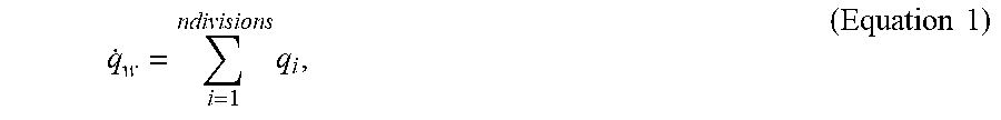
[0033] To help illustrate, FIG. 4 is a flow chart of a method 400 for iteratively calculating well conditions during a shut-in stage. Initially, at block 402, a time count is advanced. If the method 400 is initially starting, the time count may be advanced from 0 to 1. Additionally, the time count may be advanced by 1 for all subsequent actions at block 402.
[0034] At block 404, the flowrate in the reservoir (e.g., the formation 110/134) is calculated. In an embodiment, the flowrate is calculated using equation 1, provided above, which is a summation of the flowrates from the individual divisions of the wellbore 108 that include fluid at the specific time step. Additionally, the flowrates from the individual divisions of the wellbore 108 are calculated using equation 2. As the time steps progress, certain divisions may no longer include fluid as the stimulating fluid flows out of the wellbore 108 into the formation 110/134 when the reservoir pressure is less than the hydrostatic pressure of the wellbore 108. Accordingly, the divisions without fluid do not contribute to the flowrate in the reservoir of equation 1.
[0035] Using the calculated flowrate, the fluid level drop is computed at block 406. In an embodiment, the fluid level drop is calculated using equation 3, which provides the equation to calculate the liquid level within the wellbore. Accordingly, the fluid level drop for the individual time step may be calculated by subtracting the liquid level value of the current time step from the liquid level value of the previous time step.
[0036] Subsequently, at block 408, grid elements (e.g., divisions) are updated with appropriate fluid amounts. For example, based on the liquid level within the wellbore 108 calculated at block 406, the controller 120 may determine that one or more divisions 302 no longer include the stimulation fluid and are instead filled with air. The reduction in fluid within the wellbore 108 may have an impact on the hydrostatic pressure within the wellbore 108, and the reduction in fluid within the wellbore 108 may also have an impact on the overall flow rate provided by equation 1.
[0037] Accordingly, at block 410, the hydrostatic pressure and temperature within the wellbore 108 are calculated. By way of example, the hydrostatic pressure may be calculated based on a function of gravity, density, and a depth of the hydrostatic pressure measurement. Additionally, the temperature within the wellbore 108 is calculated using equation 4. As the liquid level within the wellbore 108 decreases, the hydrostatic pressure within the wellbore 108 also decreases until the hydrostatic pressure equilibrates with the reservoir pressure of the formation 110/134. Similarly, the temperature within the wellbore 108 also increases or decreases until the temperature reaches an equilibrium with the reservoir temperature. An increase or decrease in the temperature within the wellbore 108 may also result in subtle increases or decreases in hydrostatic pressure within the wellbore 108 as the temperature of the stimulating fluid and gases within the wellbore 108 increase or decrease. Subsequently at block 412, a next time step is reached and the time count is advanced at block 402. When the time count is advanced at block 402, the method 400 repeats the calculations for the next time step.
[0038] With the information gathered at each time step during the method 400, the porosity and permeability of the formation 110/134 is calculated. The porosity and permeability of the formation 110/134 may be calculated using Darcy's law to calculate the permeability and a known correlation between porosity and permeability to calculate the porosity. With the porosity and permeability of the formation 110/134, a more accurate prediction of production from the well 102 is available.
[0039] FIG. 5 is a graph 500 of a bottom-hole pressure of the wellbore 108 over time during a shut-in stage and a pumping stage of the well 102. A line 502 represents the bottom-hole pressure of the wellbore 108 over the course of the pumping stage, the shut-in stage, and the beginning of a subsequent pumping stage. An abscissa 504 provides an indication of time, and an ordinate 506 provides an indication of the bottom-hole pressure of the wellbore 108 in pounds per square inch (psi). Point 508 represents initialization of the bottom-hole pressure measurement. At point 510, which occurs just after point 508, a pumping stage begins. During the pumping stage, stimulating fluid, such as acidizing fluid or fracturing fluid, is pumped into the wellbore 108 from the wellhead 113. As shown in the graph 500, the bottom-hole pressure of the wellbore 108 increases from point 510 to point 512.
[0040] Subsequently, at point 512, the shut-in stage begins. During the shut-in stage, the stimulating fluid is no longer pumped into the wellbore 108 at the wellhead 113. Accordingly, the bottom-hole pressure rapidly declines once the shut-in stage begins. Additionally, as the shut-in stage approaches point 514, the rapid decline of the bottom-hole pressure begins to level off as a difference in reservoir pressure of the formation 110/134 and the hydrostatic pressure of the wellbore 108 decreases. The equalization of the reservoir pressure and the hydrostatic pressure is a result of the stimulation fluid leak off into the formation 110/134. When the stimulation fluid leaks off, the fluid level within the wellbore 108 decreases, and the bottom-hole pressure, as shown in the graph 500, decreases until equalization with the reservoir pressure is achieved.
[0041] In an embodiment, at point 514, a new pumping stage begins. The new pumping stage includes pumping additional stimulation fluid into the wellbore 108 to occupy empty space within the wellbore 108 resulting from fluid leak off into the formation 110/134. As shown, the bottom-hole pressure of the wellbore 108 during the new pumping stage increases rapidly as stimulation fluid is pumped into the wellbore 108 from the wellhead 113. Once a desired pressure is reached, such as a fracturing pressure, a new shut-in stage may begin (not shown), and the process may repeat itself. This process may be repeated until indications of permeability and porosity within the formation 110/134 is sufficient for reservoir fluid production. Further, as the shut-in stages occur, the controller 120 may use equations 1-9 to calculate the permeability and the porosity of the formation 110/134 and estimate production parameters of the well 102.
[0042] FIG. 6 is a graph 600 of a bottom-hole temperature of the wellbore 108 over time during a shut-in stage and a pumping stage of the well 102. A line 602 represents the bottom-hole temperature of the wellbore 108 over the course of the shut-in stage and the beginning of the pumping stage. An abscissa 604 provides an indication of time, and an ordinate 606 provides an indication of the bottom-hole temperature of the wellbore 108 in degrees Fahrenheit. As in FIG. 5, point 508 also represents initialization of the bottom-hole temperature measurement. At point 510, which occurs just after point 508, a pumping stage begins. During the pumping stage, stimulating fluid, such as acidizing fluid or fracturing fluid, is pumped into the wellbore 108 from the wellhead 113. As shown in the graph 600, the bottom-hole temperature of the wellbore 108 decreases from point 510 to point 512 as the stimulating fluid is pumped into the wellbore 108 from the wellhead 113. In the illustrated embodiment, the decrease in temperature is a result of the stimulating fluid having an initial temperature that is less than a temperature of the formation 110/134 surrounding the wellbore 108.
[0043] Subsequently, at point 512, the shut-in stage begins. During the shut-in stage, the stimulating fluid is no longer pumped into the wellbore 108 at the wellhead 113. Accordingly, the bottom-hole temperature increases as the stimulation temperature equilibrates with the reservoir temperature during the shut-in stage. As the shut-in stage approaches point 514, the increase in the bottom-hole temperature begins to level off as a difference in the reservoir temperature of the formation 110/134 and the temperature of the fluid within the wellbore 108 decreases. The equalization of the reservoir temperature and the fluid temperature within the wellbore 108 is a result of the stimulation fluid leak off into the formation 110/134 and a surface area of the fluid within the wellbore 108 that is in contact with the formation 110/134 decreasing. When the stimulation fluid leaks off, the fluid level within the wellbore 108 decreases, and the bottom-hole temperature, as shown in the graph 500, increases until equalization with the reservoir temperature is achieved. In another embodiment, the reservoir temperature is less than the stimulation fluid temperature. In such an embodiment, the equilibration of the bottom-hole temperature results in a decrease in the bottom-hole temperature of the wellbore 108 during the shut-in stage.
[0044] At point 514, a new pumping stage begins. The new pumping stage includes pumping additional stimulation fluid into the wellbore 108 to occupy empty space within the wellbore 108 resulting from fluid leak off into the formation 110/134. As shown, the bottom-hole temperature of the wellbore 108 during the new pumping stage decreases rapidly as stimulation fluid is pumped into the wellbore 108 from the wellhead 113. As discussed above with reference to FIG. 5, once a desired bottom-hole pressure is reached, such as a fracturing pressure, a new shut-in stage may begin (e.g., as indicated by a rise in temperature), and the process may repeat itself. This process may be repeated until indications of permeability and porosity within the formation 110/134 are sufficient for production. Further, as the shut-in stages occur, the controller 120 may use equations 1-9 to calculate the permeability and the porosity of the formation 110/134 and estimate production parameters of the well 102.
[0045] FIG. 7 is a flow chart of a method 700 for updating calculations of permeability of the formation 110/134 during a shut-in stage. Initially, at block 702, a permeability value of the formation 110/134 is initialized. In an embodiment, the initial permeability value of the formation 110/134 may be determined based on logs of the formation 110/134 that are generated during core sampling processes.
[0046] After the permeability value is initialized, a flowrate in the reservoir (e.g., the formation 110/134) is calculated at block 704. In an embodiment, the flowrate is calculated using equation 1, provided above, which is a summation of the flowrates from the individual divisions of the wellbore 108 that include stimulation fluid at a specific time step during which the method occurs. Additionally, the flowrates from the individual divisions of the wellbore 108 are calculated using equation 2. As the method 700 iterates, certain divisions of the wellbore 108 may no longer include fluid as the stimulating fluid flows out of the wellbore 108 into the formation 110/134 when the reservoir pressure is less than the hydrostatic pressure of the wellbore 108. Accordingly, the divisions without fluid do not contribute to the flowrate in the reservoir of equation 1.
[0047] Using the calculated flowrate, the fluid level drop is computed at block 706. In an embodiment, the fluid level drop is calculated using equation 3, which provides the equation to calculate the liquid level within the wellbore 108. Accordingly, the fluid level drop for an iteration of the method 700 may be calculated by subtracting the liquid level value of the current iteration from the liquid level value of the previous iteration.
[0048] Subsequently, at block 708, grid elements (e.g., divisions) are updated with appropriate fluid amounts. For example, based on the liquid level within the wellbore calculated at block 706, the controller 120 may determine that one or more divisions 302 no longer include the stimulation fluid and are instead filled with air. The reduction in fluid within the wellbore 108 may have an impact on the hydrostatic pressure within the wellbore 108.
[0049] At block 710, the hydrostatic pressure and temperature within the wellbore 108 are calculated. As mentioned above, the hydrostatic temperature is measured based on a function of the gravity, the density, and the bottom-hole depth. The temperature within the wellbore 108 is calculated using equation 4. As the liquid level within the wellbore 108 decreases, the hydrostatic pressure within the wellbore 108 also decreases until the hydrostatic pressure equilibrates with the reservoir pressure of the formation 110/134. Similarly, during the shut-in stage, the temperature within the wellbore 108 increases or decreases until the temperature reaches an equilibrium with the reservoir temperature. An increase or decrease in the temperature within the wellbore 108 may also result in subtle increases or decreases in hydrostatic pressure within the wellbore 108 as the temperature of the stimulating fluid within the wellbore 108 increases or decreases.
[0050] At block 712, a difference is determined between the computed temperature within the wellbore 108 and a distributed temperature sensing (DTS) system temperature measurement received from block 714. The DTS system temperature measurement provides real-time temperature sensing within the wellbore 108 to the controller 120. The controller 120 uses the DTS system temperature measurements to improve an accuracy of the model provided by the flow rate and temperature models (e.g., equations 1 and 4) when the DTS system is available. At block 712, the controller 120, for example, compares a difference between the computed temperature provided by equation 4 and the measured temperature from the DTS system to a tolerance value. By way of example, the tolerance value may be 1 degree Fahrenheit, 1 degree Celsius, or any other value that is determined to be sufficiently accurate. By way of example, the tolerance value may be established based on the DTS system measurement resolution. In an embodiment with a 1 degree Celsius tolerance value, the DTS temperature resolution may be between approximately 0.5 and 1 degree Celsius.
[0051] If the difference between the computed temperature and the DTS system measured temperature is greater than the tolerance value, then a determination is made as to whether the computed temperature is greater than the DTS system measured temperature at block 716. If the computed temperature is not greater than the DTS system measured temperature, then a new flow rate is established at block 718. In an embodiment, the new flow rate is equal to the previous flow rate, as calculated at block 704 or as calculated in a previous iteration, divided by 1.75. The divider of 1.75 is used as an example, but it may be appreciated that a larger or smaller divider is also contemplated. For example, the divider may be as low as 1.25 or as high as 2 to efficiently determine a more accurate flow rate.
[0052] Further, if the computed temperature is greater than the DTS system measured temperature, then a new flow rate is establish at block 720. In an embodiment, the new flow rate is equal to the previous flow rate, as calculated at block 704 or as calculated in a previous iteration, multiplied by two. The multiplier of two is used as an example, but it may be appreciated that a larger or smaller multiplier is also contemplated. For example, the multiplier may be as low as 1.25 or as high as 3 to efficiently determine a more accurate flow rate.
[0053] After the new flow rate is established in either blocks 718 or 720, a new fluid level drop is calculated, at block 706, based on the new flow rate. A loop including blocks 706-720 may iterate until the difference between the computed temperature and the DTS system measured temperature is within an acceptable tolerance value at block 712. Once confirmation is established that the difference is within the acceptable tolerance value, the new flow rate is accepted at block 722. Using the accepted flow rate, the permeability of the formation 110/134 is updated at block 724 using Darcy's law. It may be appreciated that the method 700 may be iterated during the shut-in stage such that the permeability of the formation 110/134 is monitored at near real-time. The permeability at each iteration of the method 700 may be stored in the memory 122 of the controller 120 for use in determining production capabilities of the well 102.
[0054] The above-disclosed embodiments have been presented for purposes of illustration and to enable one of ordinary skill in the art to practice the disclosure, but the disclosure is not intended to be exhaustive or limited to the forms disclosed. Many insubstantial modifications and variations will be apparent to those of ordinary skill in the art without departing from the scope and spirit of the disclosure. For instance, although the flowcharts depict a serial process, some of the steps/processes may be performed in parallel or out of sequence, or combined into a single step/process. The scope of the claims is intended to broadly cover the disclosed embodiments and any such modification. Further, the following clauses represent additional embodiments of the disclosure and should be considered within the scope of the disclosure:
[0055] Clause 1, a method for determining fluid level drop and formation permeability during wellbore stimulation of a shut-in stage in real time, comprising: receiving an initial permeability value of a formation surrounding a wellbore; and performing, and if necessary repeating at a defined time interval, the following steps until a flowrate of stimulation fluid reaches zero or until a new pumping stage begins: solving for the flowrate of the stimulation fluid in the wellbore;
[0056] computing hydrostatic pressure and a computed temperature in the wellbore; and updating a permeability calculation of the formation based on the flowrate of the stimulation fluid.
[0057] Clause 2, the method of clause 1, comprising: receiving a measured temperature from a distributed temperature sensing (DTS) system; and updating the flowrate based on a comparison of the computed temperature and the measured temperature when an accuracy of the flowrate is not acceptable.
[0058] Clause 3, the method of clause 2, wherein updating the flowrate when the accuracy of the flowrate is not acceptable comprises: determining whether the computed temperature is greater than the measured temperature; when the computed temperature is greater than the measured temperature, doubling the flowrate; and when the computed temperature is less than the measured temperature, dividing the flowrate by 1.75.
[0059] Clause 4, the method of at least one of clauses 2-3, comprising: determining whether the accuracy of the flowrate is acceptable, wherein determining whether the accuracy of the flowrate is acceptable comprises: determining whether a difference between the computed temperature and the measured temperature exceeds a tolerance value.
[0060] Clause 5, the method of at least one of clauses 1-4, comprising: computing a fluid level drop within the wellbore based on the flowrate; and updating stimulation fluid presence in divisions of the wellbore based on the fluid level drop.
[0061] Clause 6, the method of at least one of clauses 1-5, wherein the permeability calculation of the formation is determined based on Darcy's law.
[0062] Clause 7, the method of at least one of clauses 1-6, wherein solving for the flowrate of the stimulation fluid in the wellbore comprises: calculating an individual flow rate of each division of the wellbore; and adding together the individual flow rates of each division of the wellbore.
[0063] Clause 8, the method of at least one of clauses 1-7, wherein the initial permeability value of the formation is based on logs produced from core samples of the formation.
[0064] Clause 9, the method of at least one of clauses 1-8, wherein the stimulation fluid comprises fracturing fluid or acidizing fluid.
[0065] Clause 10, the method of at least one of clauses 1-9, wherein the defined time steps comprise one second increments of time.
[0066] Clause 11, a system for determining formation permeability during wellbore stimulation, comprising: a distributed temperature sensing (DTS) system comprising a fiber optic cable extending a length of a wellbore, wherein the DTS system is configured to provide a real-time measurement of a measured temperature of the wellbore; a controller communicatively coupled to the DTS system, the controller comprising a processor and a memory, wherein the memory comprises instructions, that when executed, cause the processor to: receive an initial permeability value of a formation surrounding the wellbore; and perform, and if necessary repeat at a defined time interval, the following instructions until a flowrate of stimulation fluid reaches zero or until a new pumping stage begins: solve for the flowrate of the stimulation fluid in the wellbore; compute hydrostatic pressure and computed temperature in the wellbore; compare the computed temperature to the measured temperature to determine accuracy of the flowrate; update the flowrate when the accuracy of the flowrate is not acceptable; and update a permeability calculation of the formation based on the flowrate of the stimulation fluid.
[0067] Clause 12, the system of clause 11, wherein the stimulation fluid comprises acidizing fluid or fracturing fluid.
[0068] Clause 13, the system of clause 11 or 12, wherein the initial permeability value of the formation is based on logs produced from core samples of the formation.
[0069] Clause 14, the system of at least one of clauses 11-13, wherein determining the accuracy of the flowrate comprises: determining whether a difference between the computed temperature and the measured temperature exceeds a tolerance value.
[0070] Clause 15, the system of at least one of clauses 11-14, wherein the instructions that cause the processor to solve for the flowrate of the stimulation fluid in the wellbore comprise instructions that cause the processor to: calculate an individual flow rate of each division of the wellbore; and add together the individual flow rates of each division of the wellbore.
[0071] Clause 16, the system of at least one of clauses 11-15, wherein the instructions that cause the processor to update the flowrate when the accuracy of the flowrate is not acceptable comprise instructions that cause the processor to: determine whether the computed temperature is greater than the measured temperature; when the computed temperature is greater than the measured temperature, double the flowrate; and when the computed temperature is less than the measured temperature, divide the flowrate by 1.75.
[0072] Clause 17, a non-transitory machine-readable medium comprising instructions stored therein, which when executed by one or more processors, causes the one or more processors to perform operations comprising: receiving an initial permeability value of a formation surrounding a wellbore; and performing, and if necessary repeating at a defined time interval, the following operations until a flowrate of stimulation fluid reaches zero or until a new pumping stage begins; solving for the flowrate of the stimulation fluid in the wellbore; computing hydrostatic pressure and computed temperature in the wellbore; receiving a measured temperature of the wellbore; comparing the computed temperature to the measured temperature to determine accuracy of the flowrate; updating the flowrate when the accuracy of the flowrate is not acceptable; and updating a permeability calculation of the formation based on the flowrate of the stimulation fluid.
[0073] Clause 18, the medium of clause 17, wherein receiving the measured temperature of the wellbore comprises receiving the measured temperature in real-time from a distributed temperature sensing (DTS) system.
[0074] Clause 19, the medium of clause 17 or 18, wherein updating the flowrate when the accuracy of the flowrate is not acceptable comprises: determining whether the computed temperature is greater than the measured temperature; when the computed temperature is greater than the measured temperature, doubling the flowrate; and when the computed temperature is less than the measured temperature, dividing the flowrate by 1.75.
[0075] Clause 20, the medium of at least one of clauses 17-19, comprising recording the permeability calculation in a memory at each time step.
[0076] While this specification provides specific details related to certain components related to dynamically modeling a formation surrounding a wellbore, it may be appreciated that the list of components is illustrative only and is not intended to be exhaustive or limited to the forms disclosed. Other components related to dynamically modeling the formation will be apparent to those of ordinary skill in the art without departing from the scope and spirit of the disclosure. Further, the scope of the claims is intended to broadly cover the disclosed components and any such components that are apparent to those of ordinary skill in the art.
[0077] It should be apparent from the foregoing disclosure of illustrative embodiments that significant advantages have been provided. The illustrative embodiments are not limited solely to the descriptions and illustrations included herein and are instead capable of various changes and modifications without departing from the spirit of the disclosure.
* * * * *
D00000
D00001
D00002
D00003
D00004
D00005
D00006


XML
uspto.report is an independent third-party trademark research tool that is not affiliated, endorsed, or sponsored by the United States Patent and Trademark Office (USPTO) or any other governmental organization. The information provided by uspto.report is based on publicly available data at the time of writing and is intended for informational purposes only.
While we strive to provide accurate and up-to-date information, we do not guarantee the accuracy, completeness, reliability, or suitability of the information displayed on this site. The use of this site is at your own risk. Any reliance you place on such information is therefore strictly at your own risk.
All official trademark data, including owner information, should be verified by visiting the official USPTO website at www.uspto.gov. This site is not intended to replace professional legal advice and should not be used as a substitute for consulting with a legal professional who is knowledgeable about trademark law.