Setting Tool For Use In A Subterranean Well
HAM; Gregory D.
U.S. patent application number 16/456046 was filed with the patent office on 2020-01-16 for setting tool for use in a subterranean well. The applicant listed for this patent is SEAFLOOR MINERAL INC.. Invention is credited to Gregory D. HAM.
| Application Number | 20200018132 16/456046 |
| Document ID | / |
| Family ID | 69138943 |
| Filed Date | 2020-01-16 |


| United States Patent Application | 20200018132 |
| Kind Code | A1 |
| HAM; Gregory D. | January 16, 2020 |
SETTING TOOL FOR USE IN A SUBTERRANEAN WELL
Abstract
A setting tool can include a generally tubular cylinder, a generally tubular piston sealingly and reciprocably received in the cylinder, and a rod separately secured to the piston, the rod blocking an axial end of a power charge chamber formed in the piston. Another setting tool can include a generally tubular cylinder, a generally tubular piston sealingly and reciprocably received in the cylinder, a rod separately secured to the piston, and at least one port that provides fluid communication between the power charge chamber and an annular space formed radially between the cylinder and the rod. The port intersects an end surface of the piston between the cylinder and the rod.
| Inventors: | HAM; Gregory D.; (Houston, TX) | ||||||||||
| Applicant: |
|
||||||||||
|---|---|---|---|---|---|---|---|---|---|---|---|
| Family ID: | 69138943 | ||||||||||
| Appl. No.: | 16/456046 | ||||||||||
| Filed: | June 28, 2019 |
Related U.S. Patent Documents
| Application Number | Filing Date | Patent Number | ||
|---|---|---|---|---|
| 62698250 | Jul 15, 2018 | |||
| Current U.S. Class: | 1/1 |
| Current CPC Class: | E21B 23/06 20130101; E21B 23/04 20130101; E21B 33/1292 20130101; E21B 23/065 20130101 |
| International Class: | E21B 23/04 20060101 E21B023/04; E21B 23/06 20060101 E21B023/06 |
Claims
1. A setting tool for use in a subterranean well to set a well tool, the setting tool comprising: a generally tubular cylinder; a generally tubular piston sealingly and reciprocably received in the cylinder; and a rod separately secured to the piston, the rod blocking an axial end of a power charge chamber formed in the piston.
2. The setting tool of claim 1, in which at least one port provides fluid communication between the power charge chamber and an annular space formed radially between the cylinder and the rod.
3. The setting tool of claim 2, in which the port extends through the rod.
4. The setting tool of claim 2, in which the port extends through the piston.
5. The setting tool of claim 2, in which the port extends through a portion of the piston radially between an exterior circumference of the piston and threads that connect the rod to the piston.
6. The setting tool of claim 2, in which the port intersects an end surface of the piston between the cylinder and the rod.
7. The setting tool of claim 2, in which the port intersects a portion of the power charge chamber not blocked by the rod.
8. The setting tool of claim 1, further comprising a guide bushing extending radially between the cylinder and the rod, the guide bushing being sealingly secured to the cylinder, and the guide bushing being slidingly and sealingly engaged with the rod.
9. The setting tool of claim 8, in which the guide bushing is separate from the cylinder and is threadedly secured to the cylinder.
10. The setting tool of claim 8, further comprising a setting sleeve extending outwardly from the guide bushing.
11. The setting tool of claim 10, in which the setting sleeve is integrally formed with the guide bushing.
12. A setting tool for use in a subterranean well to set a well tool, the setting tool comprising: a generally tubular cylinder; a generally tubular piston sealingly and reciprocably received in the cylinder, in which a power charge chamber is formed in the piston; a rod separately secured to the piston; and at least one port that provides fluid communication between the power charge chamber and an annular space formed radially between the cylinder and the rod, in which the port intersects an end surface of the piston between the cylinder and the rod.
13. The setting tool of claim 12, in which the port extends through a portion of the piston radially between an exterior circumference of the piston and threads that connect the rod to the piston.
14. The setting tool of claim 12, in which the rod blocks an axial end of the power charge chamber.
15. The setting tool of claim 14, in which the ports intersect a portion of the power charge chamber not blocked by the rod.
16. The setting tool of claim 12, further comprising a guide bushing extending radially between the cylinder and the rod, the guide bushing being sealingly secured to the cylinder, and the guide bushing being slidingly and sealingly engaged with the rod.
17. The setting tool of claim 16, in which the guide bushing is separate from the cylinder and is threadedly secured to the cylinder.
18. The setting tool of claim 16, further comprising a setting sleeve extending outwardly from the guide bushing.
19. The setting tool of claim 18, in which the setting sleeve is integrally formed with the guide bushing.
20. The setting tool of claim 12, in which a shear pin releasably secures the cylinder against axial displacement relative to the piston, and in which the shear pin is press-fit into at least one of the group consisting of a first hole in the cylinder and a second hole in the piston.
Description
CROSS-REFERENCE TO RELATED APPLICATION
[0001] This application claims the benefit of the filing date of U.S. provisional application No. 62/698,250 filed on 15 Jul. 2018. The entire disclosure of this prior application is incorporated herein by this reference.
BACKGROUND
[0002] This disclosure relates generally to equipment utilized and operations performed in conjunction with a subterranean well and, in an example described below, more particularly provides a setting tool.
[0003] Well packers and plugs are often put into wells and secured in place using setting tools. Setting a packer or plug typically involves compressing a seal element in an axial direction such that it expands outward and seals against an inside of a wellbore or a well casing. Setting tools often perform this compression by holding a center section of the packer or plug stationary while driving an outer section downward. This action drives wedges and cones against elastomer seal elements that are thereby enlarged radially so a seal is created between the plug or packer and the wellbore or well casing. During the setting operation a shear pin may shear and release the setting tool from the set packer or plug, so that the setting tool may be retrieved from the well.
[0004] Numerous types of setting tools have been employed. Most setting tools are propellant-actuated, in which flammable power charges are burned to generate pressurized gases that displace one or more pistons, in order to set the packer or plug. Some setting tools utilize hydraulic oil as an intermediary to transfer the force of the power charge to the actuator of the setting tool. Other setting tools use the pressurized gases to directly actuate the setting tool without employing hydraulic oil. Setting tools can either be reusable or disposable.
BRIEF DESCRIPTION OF THE DRAWINGS
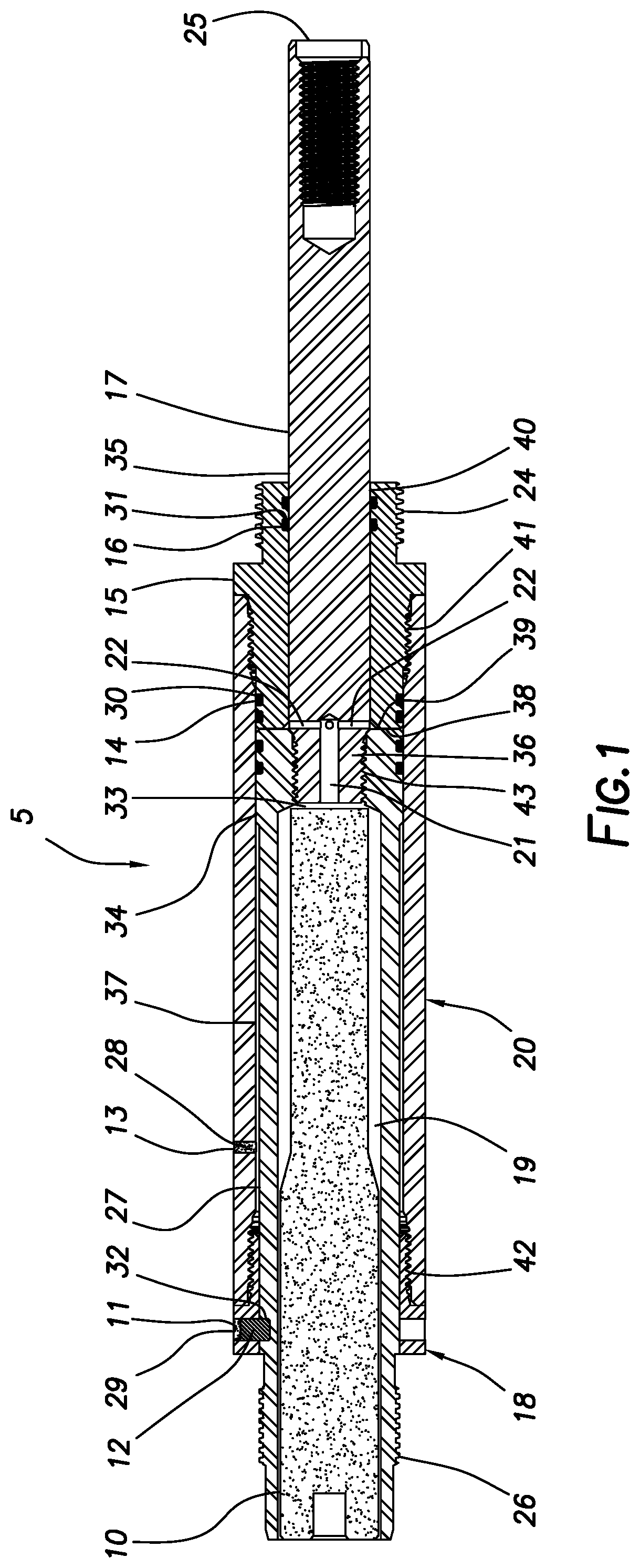
[0005] FIG. 1 is a representative cross-sectional view of an example of a setting tool and associated method which can embody principles of this disclosure.
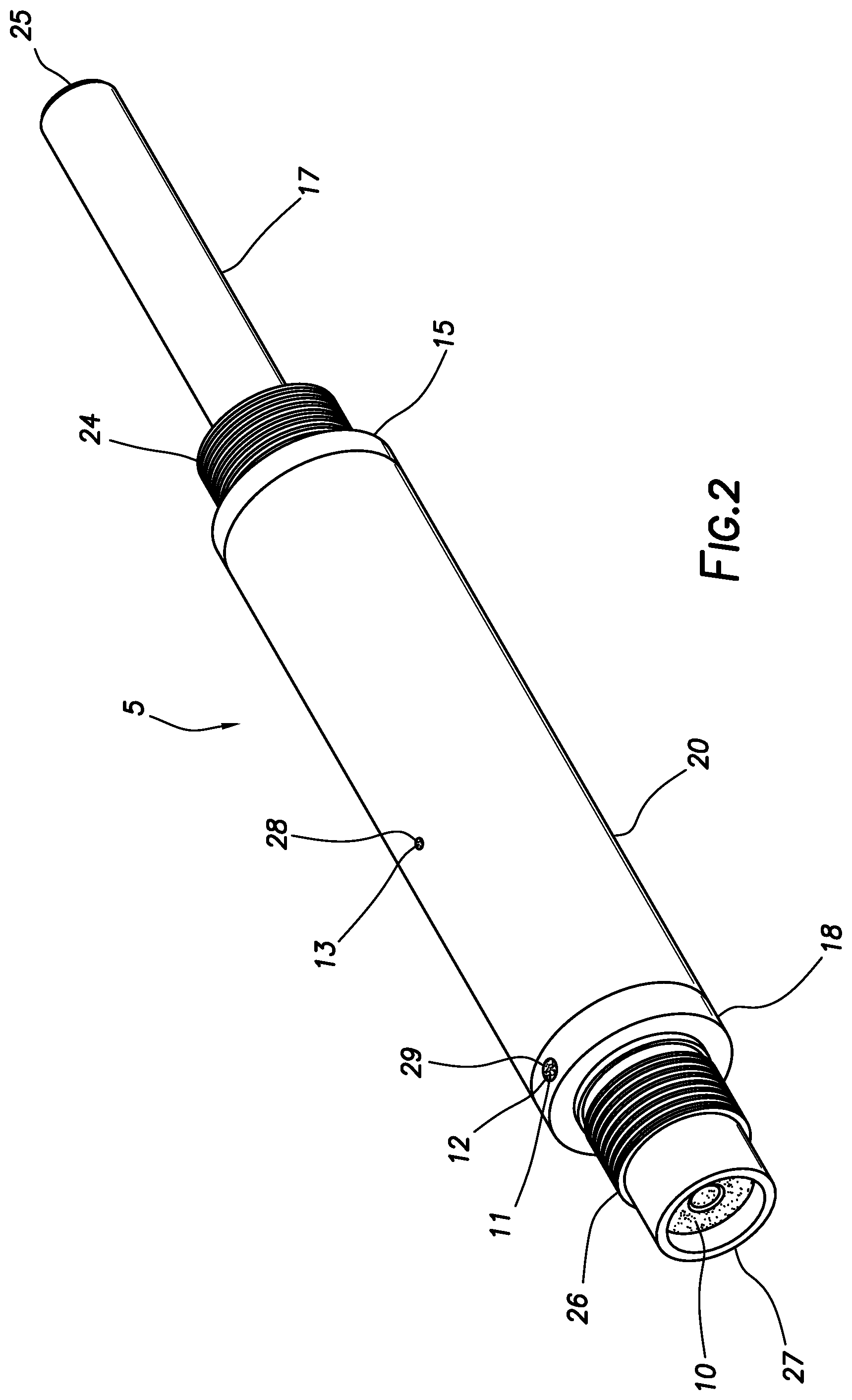
[0006] FIG. 2 is a representative perspective view of the setting tool in a run-in configuration.
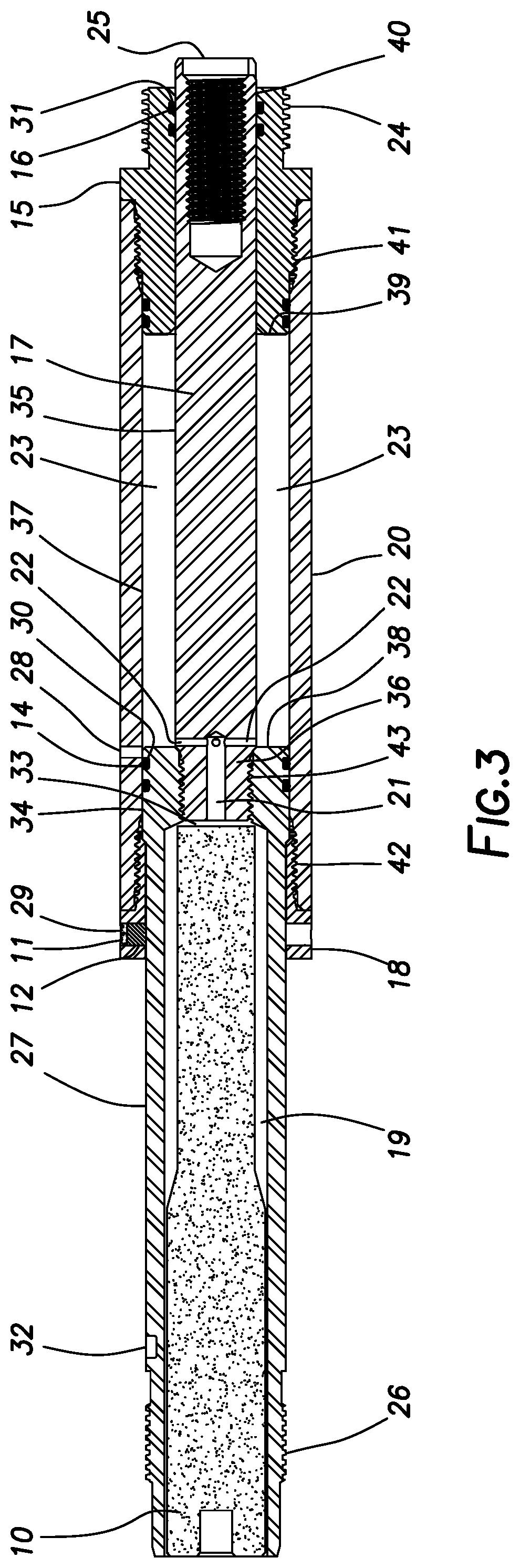
[0007] FIG. 3 is a representative cross-sectional view of the setting tool in an actuated configuration.
[0008] FIG. 4 is a representative perspective view of the setting tool in the actuated configuration.
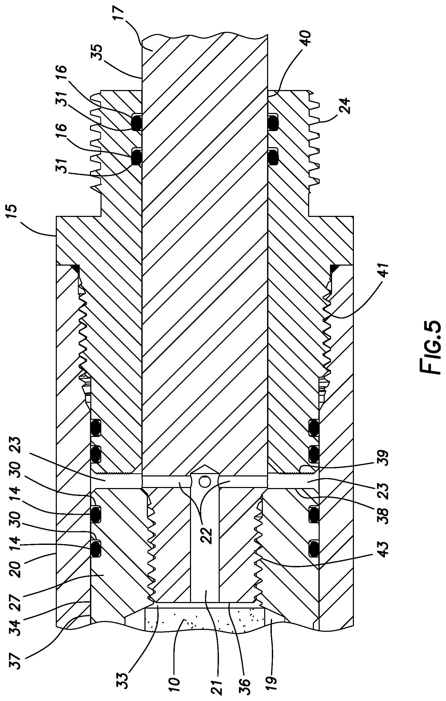
[0009] FIG. 5 is a representative cross-sectional view of a portion of the setting tool in the run-in configuration.
[0010] FIG. 6 is a representative cross-sectional view of another example of the setting tool connected to a well tool in a well.
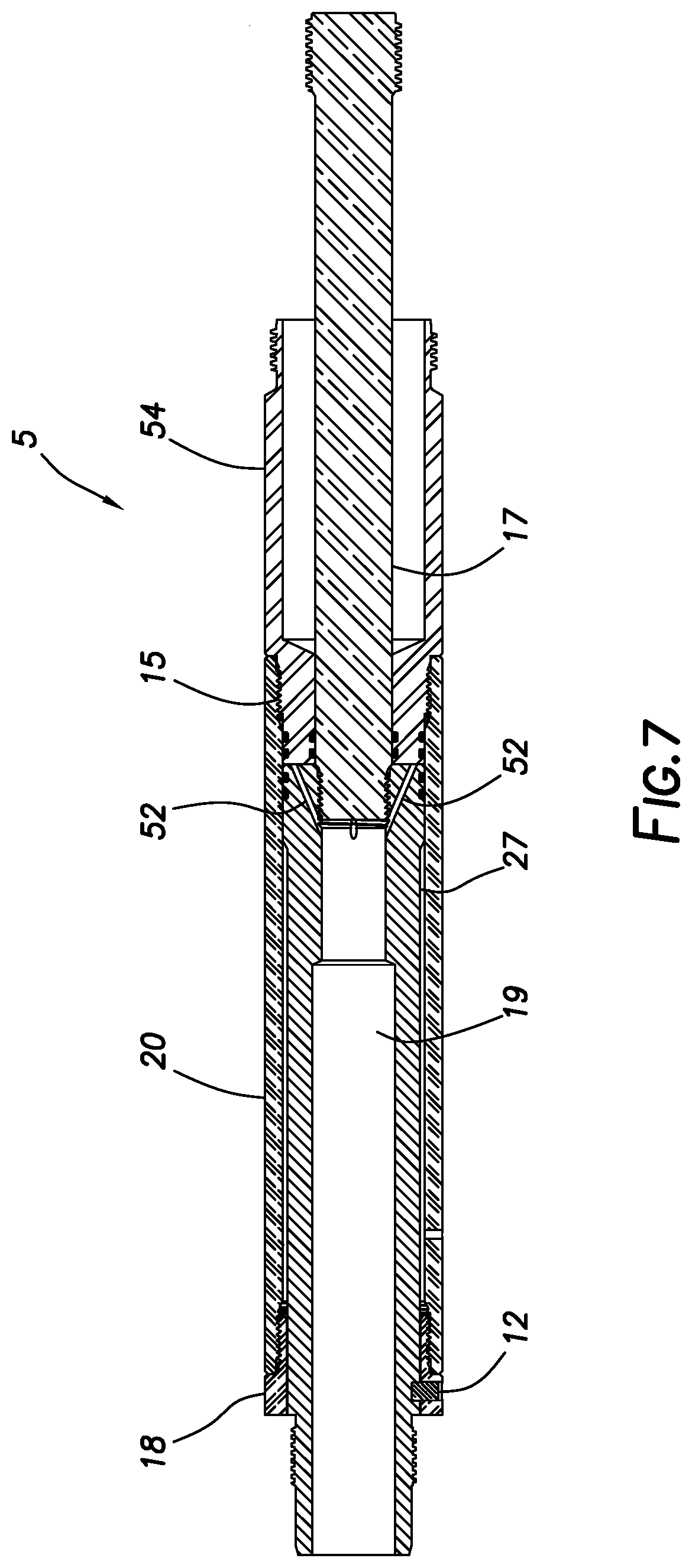
[0011] FIG. 7 is a representative cross-sectional view of the FIG. 6 setting tool in a run-in configuration.
[0012] FIG. 8 a representative cross-sectional view of the FIG. 6 setting tool in an actuated configuration.
[0013] FIG. 9 is a representative cross-sectional view of a portion of the FIG. 6 setting tool.
DETAILED DESCRIPTION
[0014] Representatively illustrated in FIG. 1 is a setting tool 5 and associated method which can embody principles of this disclosure. However, it should be clearly understood that the setting tool 5 and method are merely one example of an application of the principles of this disclosure in practice, and a wide variety of other examples are possible. Therefore, the scope of this disclosure is not limited at all to the details of the setting tool 5 and method described herein and/or depicted in the drawings.
[0015] In the FIG. 1 example, the setting tool 5 is desirably compact, and uncomplicated to assemble and actuate. The setting tool 5 is propellant-actuated and is used to set plugs, packers and other types of well tools in well casing or open hole wellbores.
[0016] As described more fully below, the FIG. 1 setting tool 5 has a piston, a rod, a sealed guide bushing, a retaining collar, a shear pin and a cylinder. The piston has an interior chamber into which a power charge is inserted prior to use of the setting tool 5 at a wellsite. The rod mechanically attaches to the piston, accessing the power charge chamber at one end.
[0017] The piston and rod form a rigid assembly. The sealed guide bushing mechanically attaches to the lower end of the cylinder. The cylinder and the sealed guide bushing form an assembly that slides axially along the piston and rod assembly.
[0018] In the FIG. 1 example, an annular-shaped space is formed between the sealed guide bushing and the piston. The rod has axial and radial ports that connect to form passages which communicate the pressurized gases from the power charge chamber to the annular-shaped space. The gas pressure in the annular-shaped space acts against the sealed guide bushing driving the cylinder and the sealed guide bushing downward along the axial length of the rod.
[0019] The gas pressure inside the annular-shaped space is retained by fluidic seals in grooves on the outer surface of the piston. These seals prevent the pressurized gases from passing between the piston outer surface and the cylinder inner surface. The sealed guide bushing has grooves on its inner bore that allow for the placement of fluidic seals. These seals prevent the pressurized gases from passing between the rod and the sealed guide bushing.
[0020] In this example, the retaining collar attaches to the upper end of the cylinder and holds a shear pin that protrudes into a hole formed in the outer surface of the piston. The shear pin carries the weight of the tool string during run-in or installation in the well. However, once the power charge is ignited, the shear pin is sheared, thereby allowing the setting tool to actuate.
[0021] The upper end of the piston has threads and seals for attaching to a firing head. The lower end of the rod is adapted for connecting to a well tool mandrel. The lower end of the seal guide bushing is adapted for connecting to the setting sleeve of the well tool below the setting tool.
[0022] In the FIG. 1 example, the power charge is placed in the power charge chamber and is ignited to generate pressurized gas. The pressurized gas enters the annular-shaped space and causes the cylinder and sealed guide bushing to stroke axially along the rod and piston assembly. The piston and rod assembly is held stationary while the cylinder and sealed guide bushing move the well tool's setting sleeve relative to the stationary mandrel, thereby causing the well tool to set.
[0023] As depicted in FIGS. 1 & 2, the compact setting tool 5 is in the run-in configuration, in which it may be connected to a well tool (such as, a plug, a packer, a liner hanger, etc.) that can be set in a well. The scope of this disclosure is not limited to use of the setting tool 5 with any particular type of well tool.
[0024] The setting tool 5 has a generally tubular piston 27, a rod 17, a sealed guide bushing 15, a retaining collar 18, a shear pin, a power charge 10, and a cylinder 20. The piston 27 has a power charge chamber 19, an exterior circumference 34, and grooves 30 fitted with fluid pressure seals 14.
[0025] An upper region 26 of the piston 27 is designed to mechanically connect and seal with a firing head or firing head adapter (not shown, see FIG. 6). The piston 27 has a hole 32 formed in its outer surface to receive a shear pin 12 inserted through a hole 29 in the retaining collar 18. The shear pin 12 may be press-fit in at least one of the holes 29, 32.
[0026] A lower region 43 of the piston 27 is internally threaded to form a mechanical connection with an upper threaded section 36 of the rod 17. The rod 17 has an exterior circumference 35 which slidably engages with the sealed guide bushing 15 and its seals 16.
[0027] The rod 17 has one or more axial flow ports 21 which are in fluid communication with one or more radial flow ports 22. The upper threaded section 36 connects to the lower end of the piston 27 and provides a fluid connection to a lower region 33 of the power charge chamber 19. The rod 17 has a lower threaded connection 25 which connects to a well tool mandrel (not shown in FIG. 1, see FIG. 6) located below the setting tool 5.
[0028] The sealed guide bushing 15 has an interior circumference 40 and internal grooves 31 fitted with the fluid pressure seals 16. Additionally, the sealed guide bushing 15 has an upper threaded connection 41 which mechanically connects and seals the sealed guide bushing 15 to the lower end of the cylinder 20. Additionally, the sealed guide bushing 15 has a lower threaded connection 24 which connects to the setting sleeve of the well tool (not shown in FIG. 1, see FIG. 6) located below the setting tool 5.
[0029] The retaining collar 18 has a threaded section 42 that mechanically connects to the upper end of the cylinder 20. The retaining collar 18 has a hole 29 that contains a shear pin 12 held in place with a pliable potting compound 11. The shear pin 12 protrudes through the retaining collar 18 and into a shallow hole 32 formed into the upper end of the piston 27.
[0030] The cylinder 20 has an interior circumference 37. Each end of the cylinder 20 is threaded (at 41, 42). The upper threaded section 42 mechanically connects with the retaining collar 18. The lower threaded connection 41 mechanically connects and seals with the sealed guide bushing 15.
[0031] The cylinder 20 has a vent hole 28 formed in its side. The vent hole 28 is filled with a pliable potting compound 13. After actuation of the setting tool 5 (see FIGS. 3 & 4) this hole 28 is exposed to pressurized gas in the annular-shaped space 23. The pressurized gas pushes out the pliable potting compound 13 and then vents the pressurized gas from the annular-shaped space 23 into the wellbore.
[0032] FIG. 3 shows a section view of the setting tool 5 in the actuated configuration. The shear pin 12 has been sheared. The vent hole 28 is in fluid communication with the annular-shaped space 23. The annular-shaped space 23 is lengthened due to the stroking of the sealed guide bushing 15 and the cylinder 20. Additionally, an axial distance between the lower threaded connection 24 on the sealed guide bushing 15 and the lower threaded connection 25 on the rod 17 has been significantly reduced, indicating that the well tool connected thereto has been set.
[0033] FIG. 5 depicts the annular-shaped space 23 that extends radially between the exterior circumference 35 of the rod 17 and the interior circumference 37 of the cylinder 20. Additionally, the annular-shaped space 23 extends axially between a lower end surface 38 of the piston 27 and an upper end surface 39 of the sealed guide bushing 15. The lower region 33 of the power charge chamber 19 is in fluid communication with the annular-shaped space 23 via the axial flow ports 21 and the radial flow ports 22 in the rod 17.
[0034] Upon ignition, the power charge 10 generates pressurized gases in the power charge chamber 19. The pressurized gases move through the axial ports 21 and the radial ports 22 within the rod 17 and enter the annular-shaped space 23. The pressurized fluids act on the sealed guide bushing 15 causing the shear pin 12 to shear and forcing the sealed guide bushing 15 and the attached cylinder 20 downward into an actuated or set position.
[0035] Referring additionally now to FIG. 6, a cross-sectional view of another example of the setting tool 5 is representatively illustrated. In this example, the setting tool 5 is being used to set a well tool 46 in a wellbore 48. The wellbore 48 may be lined with casing 50 or another type of wellbore lining, or the wellbore may be uncased or open hole in other examples.
[0036] The FIG. 6 setting tool 5 is similar in many respects to the FIGS. 1-5 setting tool described above. Note, however, that the FIG. 6 setting tool 5 does include some differences over the FIGS. 1-5 setting tool.
[0037] The guide bushing 15 and a setting sleeve 54 are combined or integrated into a single component in the FIG. 6 setting tool 5. In other examples, the setting sleeve 54 could be a separate component from the guide bushing 15 (e.g., as in the FIGS. 1-5 example).
[0038] An adapter 56 connects between the setting sleeve 54 and upper slips 58 of the well tool 46. The setting sleeve 54 and the adapter 56 allow a compressive force to be applied from the guide bushing 15 and the cylinder 20 to the upper slips 58 and other outer components of the well tool 46, as described more fully below.
[0039] In addition, ports 52 provide fluid communication between the power charge chamber 19 and the annular space 23 axially between the piston 27 and the guide bushing 15, and radially between the rod 17 and the cylinder 20. The ports 52 are formed in the piston 27 (instead of in the rod 17 as for the ports 21, 22 of the FIGS. 1-5 example).
[0040] A firing head 60 is connected to the upper end of the piston 27. The firing head 60 includes an ignitor 62 used to ignite the power charge 10. The ignitor 62 could be electrically or percussion-activated. An upper connector 64 of the firing head 60 may be used to connect to a conveyance (such as, a wireline, a coiled tubing string, etc.).
[0041] The well tool 46 in this example is in the form of a bridge plug. An inner mandrel 66 extends axially between a lower head 68 and a releasable setting connector 70. The setting connector 70 includes an internally threaded sleeve 72 releasably secured in an upper end of the inner mandrel 66 by shear pins 74.
[0042] The sleeve 72 is threaded to a lower end of the rod 17. In this manner, a tensile force can be transmitted from the rod 17 to the inner mandrel 66 of the well tool 46. However, when the tensile force reaches a predetermined level, the shear pins 74 will shear, thereby freeing the rod 17 from its connection to the well tool 46.
[0043] The well tool 46 further includes the upper slips 58, lower slips 76, upper and lower conical wedges 78, 80, and a seal element 82 positioned between the wedges. When the compressive force is applied via the adapter 56 to the upper slips 58, and the opposite tensile force is applied via the rod 17 to the inner mandrel 66, the external components (the upper and lower slips 58, 76, upper and lower wedges 78, 80 and the seal element 82) on the well tool 46 will be axially compressed, thereby deforming the seal element 82, so that it extends radially outward and sealingly engages the casing 50 or wellbore 48, and thereby deflecting the slips outward into gripping engagement with the wellbore or casing.
[0044] When the tensile force transmitted from the rod 17 to the inner mandrel 66 reaches the predetermined level at which the well tool 46 is considered sufficiently set (the slips 58, 76 gripping the wellbore 48 or casing 50, and the seal element 82 sealingly engaging the wellbore or casing), the shear pins 74 shear, and then the setting tool 5 is released from the well tool. The setting tool 5 can be retrieved from the well, leaving the well tool 46 set downhole.
[0045] Referring additionally now to FIG. 7, a cross-sectional view of the setting tool 5 is representatively illustrated in the run-in configuration. The setting tool 5 is depicted apart from the well tool 46 and firing head 60 of FIG. 6. The setting tool 5 may be used with other well tools or firing heads, in keeping with the principles of this disclosure.
[0046] In FIG. 7 it may be recognized that this setting tool 5 example is made up of only four generally tubular main components (the piston 27, retaining collar 18, cylinder 20 and guide bushing 15/setting sleeve 54) and one solid main component (the rod 17). In other examples, the retaining collar 18 and the cylinder 20 could be combined or the guide bushing 15 and setting sleeve 54 could be separated. Thus, the scope of this disclosure is not limited to any particular number, shapes or combinations of components in the setting tool 5.
[0047] Note that the ports 52 extend through the piston 27 to the annular space 23 (see FIG. 8) between the piston 27 and the guide bushing 15. At an opposite end, each of the ports 52 is open to the power charge chamber 19 where it is not blocked by the rod 17. Thus, the annular space 23 is in communication with the power charge chamber 19, without extending through or being blocked by the rod 17.
[0048] Referring additionally now to FIG. 8, a cross-sectional view of the setting tool 5 is representatively illustrated in the actuated configuration. In this configuration, the power charge 10 (see FIG. 6) has burned in the chamber 19 and pressurized gases have been communicated from the chamber 19 to the annular space 23. The shear pin 12 has sheared and the guide bushing 15/setting sleeve 54, the retaining collar 18 and the cylinder 20 have been displaced axially downward (to the right as viewed in FIG. 8) relative to the rod 17 and piston 27.
[0049] Referring additionally now to FIG. 9, a cross-sectional view of a portion of the setting tool 5 is representatively illustrated in the actuated configuration. In this view it may be seen that the retaining collar 18 prevents displacement of the piston 27 out of the upper end of the cylinder 20.
[0050] In addition, it may be seen that the ports 52 intersect the power charge chamber 19 above (to the left as viewed in FIG. 9) the rod 17. The ports 52 intersect the lower surface 38 of the piston 27 between the cylinder 20 and the rod 17. The ports 52 extend through the piston 27 radially between the seals 14 and threads 44 that connect the piston to the rod 17.
[0051] It may now be fully appreciated that the above disclosure provides significant advantages to the arts of designing, constructing and utilizing setting tools for use in subterranean wells. In examples described above, the setting tool 5 is specially designed so that tubular components are separated from solid cylindrical components for reduced manufacturing cost and ease of transport and assembly. The piston 27 is separate from the rod 17. The power charge chamber 19 is not formed in the rod 17. Instead, the power charge chamber 19 is formed in the piston 27, and then the piston is connected to the rod 17 during assembly of the setting tool 5.
[0052] The above disclosure provides to the art a setting tool 5 for use in a subterranean well to set a well tool 46. In one example, the setting tool 5 can comprise: a generally tubular cylinder 20, a generally tubular piston 27 sealingly and reciprocably received in the cylinder 20, and a rod 17 separately secured to the piston 27. The rod 17 blocks an axial end (e.g., lower region 33) of a power charge chamber 19 formed in the piston 27.
[0053] In any of the examples described herein:
[0054] At least one port 52 may provide fluid communication between the power charge chamber 19 and an annular space 23 formed radially between the cylinder 20 and the rod 17. The port 52 may extend through the rod 17 and/or through the piston 27. The port 52 may extend through a portion of the piston 27 radially between an exterior circumference 34 of the piston 27 and threads 44 that connect the rod 17 to the piston 27.
[0055] The port 52 may intersect an end surface 38 of the piston 27 between the cylinder 20 and the rod 17. The port 52 may intersect a portion of the power charge chamber 19 not blocked by the rod 17.
[0056] The setting tool 5 may include a guide bushing 15 extending radially between the cylinder 20 and the rod 17, the guide bushing 15 being sealingly secured to the cylinder 20, and the guide bushing 15 being slidingly and sealingly engaged with the rod 17. The guide bushing 15 may be separate from the cylinder 20 and threadedly secured to the cylinder 20.
[0057] The setting tool 5 may include a setting sleeve 54 extending outwardly from the guide bushing 15. The setting sleeve 54 may be integrally formed with the guide bushing 15.
[0058] Also provided to the art by the above disclosure is another setting tool 5 for use in a subterranean well to set a well tool 46. In one example, the setting tool 5 can comprise: a generally tubular cylinder 20, a generally tubular piston 27 sealingly and reciprocably received in the cylinder 20, a rod 17 separately secured to the piston 27, and at least one port 52 that provides fluid communication between a power charge chamber 19 in the piston 27, and an annular space 23 formed radially between the cylinder 20 and the rod 17. The port 52 intersects an end surface 38 of the piston 27 between the cylinder 20 and the rod 17.
[0059] In any of the examples described herein:
[0060] The port 52 may extend through a portion of the piston 27 radially between an exterior circumference 34 of the piston 27 and threads 44 that connect the rod 17 to the piston 27.
[0061] The rod 17 may block an axial end of the power charge chamber 19. The ports 52 may intersect a portion of the power charge chamber 19 not blocked by the rod 17.
[0062] The setting tool 5 may include a guide bushing 15 extending radially between the cylinder 20 and the rod 17, the guide bushing 15 being sealingly secured to the cylinder 20, and the guide bushing 15 being slidingly and sealingly engaged with the rod 17. The guide bushing 15 may be separate from the cylinder 20 and threadedly secured to the cylinder 20.
[0063] The setting tool 5 may include a setting sleeve 54 extending outwardly from the guide bushing 15. The setting sleeve 54 may be integrally formed with the guide bushing 15.
[0064] A shear pin 12 may releasably secure the cylinder 20 against axial displacement relative to the piston 27. The shear pin 12 may be press-fit into at least one of a first hole 29 in the cylinder 20 and a second hole 32 in the piston 27.
[0065] Although various examples have been described above, with each example having certain features, it should be understood that it is not necessary for a particular feature of one example to be used exclusively with that example. Instead, any of the features described above and/or depicted in the drawings can be combined with any of the examples, in addition to or in substitution for any of the other features of those examples. One example's features are not mutually exclusive to another example's features. Instead, the scope of this disclosure encompasses any combination of any of the features.
[0066] Although each example described above includes a certain combination of features, it should be understood that it is not necessary for all features of an example to be used. Instead, any of the features described above can be used, without any other particular feature or features also being used.
[0067] It should be understood that the various embodiments described herein may be utilized in various orientations, such as inclined, inverted, horizontal, vertical, etc., and in various configurations, without departing from the principles of this disclosure. The embodiments are described merely as examples of useful applications of the principles of the disclosure, which is not limited to any specific details of these embodiments.
[0068] In the above description of the representative examples, directional terms (such as "above," "below," "upper," "lower," "upward," "downward," etc.) are used for convenience in referring to the accompanying drawings. However, it should be clearly understood that the scope of this disclosure is not limited to any particular directions described herein.
[0069] The terms "including," "includes," "comprising," "comprises," and similar terms are used in a non-limiting sense in this specification. For example, if a system, method, apparatus, device, etc., is described as "including" a certain feature or element, the system, method, apparatus, device, etc., can include that feature or element, and can also include other features or elements. Similarly, the term "comprises" is considered to mean "comprises, but is not limited to."
[0070] Of course, a person skilled in the art would, upon a careful consideration of the above description of representative embodiments of the disclosure, readily appreciate that many modifications, additions, substitutions, deletions, and other changes may be made to the specific embodiments, and such changes are contemplated by the principles of this disclosure. For example, structures disclosed as being separately formed can, in other examples, be integrally formed and vice versa. Accordingly, the foregoing detailed description is to be clearly understood as being given by way of illustration and example only, the spirit and scope of the invention being limited solely by the appended claims and their equivalents.
* * * * *
D00000
D00001
D00002
D00003
D00004
D00005
D00006
D00007
D00008
D00009
XML
uspto.report is an independent third-party trademark research tool that is not affiliated, endorsed, or sponsored by the United States Patent and Trademark Office (USPTO) or any other governmental organization. The information provided by uspto.report is based on publicly available data at the time of writing and is intended for informational purposes only.
While we strive to provide accurate and up-to-date information, we do not guarantee the accuracy, completeness, reliability, or suitability of the information displayed on this site. The use of this site is at your own risk. Any reliance you place on such information is therefore strictly at your own risk.
All official trademark data, including owner information, should be verified by visiting the official USPTO website at www.uspto.gov. This site is not intended to replace professional legal advice and should not be used as a substitute for consulting with a legal professional who is knowledgeable about trademark law.