Metal Extrusion Quenching Method And System With Variable Length Entry Zone
Jenista; David Rolston ; et al.
U.S. patent application number 16/034655 was filed with the patent office on 2020-01-16 for metal extrusion quenching method and system with variable length entry zone. The applicant listed for this patent is Granco Clark, Inc.. Invention is credited to Drew Thompson Griffioen, David Rolston Jenista.
| Application Number | 20200017944 16/034655 |
| Document ID | / |
| Family ID | 69138179 |
| Filed Date | 2020-01-16 |


| United States Patent Application | 20200017944 |
| Kind Code | A1 |
| Jenista; David Rolston ; et al. | January 16, 2020 |
METAL EXTRUSION QUENCHING METHOD AND SYSTEM WITH VARIABLE LENGTH ENTRY ZONE
Abstract
The specification discloses a metal extrusion quenching method and system in which multiple quenching steps are accomplished in multiple quenching zones. In a first zone, the extrusion is cooled relatively gently while the extrusion is in the pre-critical temperature range of the alloy of which the metal extrusion is fabricated. In a second zone, the extrusion is cooled relatively aggressively while the extrusion is in the critical temperature range. The first quenching zone includes a plurality of subzones each of which can be controlled independently. Consequently, the effective length of the first zone may be controlled by controlling the quenching provided in each subzone.
| Inventors: | Jenista; David Rolston; (Belmont, MI) ; Griffioen; Drew Thompson; (Portland, MI) | ||||||||||
| Applicant: |
|
||||||||||
|---|---|---|---|---|---|---|---|---|---|---|---|
| Family ID: | 69138179 | ||||||||||
| Appl. No.: | 16/034655 | ||||||||||
| Filed: | July 13, 2018 |
| Current U.S. Class: | 1/1 |
| Current CPC Class: | C22C 21/08 20130101; B21C 29/003 20130101; C22F 1/047 20130101; C22F 1/002 20130101; C21D 1/667 20130101 |
| International Class: | C22F 1/00 20060101 C22F001/00; C21D 1/667 20060101 C21D001/667; C22F 1/047 20060101 C22F001/047 |
Claims
1. A method of quenching a metal extrusion comprising: first quenching the metal extrusion in a first zone relatively gently when the temperature of the metal extrusion is approximately within the pre-critical temperature range of the alloy of which the metal extrusion is fabricated; and second and subsequently quenching the metal extrusion in a second zone relatively aggressively and relatively quickly while the temperature of the metal extrusion is approximately within the critical temperature range of the alloy of which the metal extrusion is fabricated.
2. A method as defined in claim 1 wherein: the first zone comprises a plurality of subzones; and the first quenching step includes selectively applying quenching in the subzones.
3. A method as defined in claim 2 wherein the selectively applying quenching step within each subzone includes turning quenching on or off.
4. A method as defined in claim 3 wherein the selectively applying quenching step within each subzone includes quenching with mist.
5. A method as defined in claim 1 wherein the first quenching step comprises quenching with mist.
6. A quenching system for a metal extrusion comprising: a first quenching zone in which the metal extrusion is quenched relatively gently while the temperature of the metal extrusion is approximately within the pre-critical temperature range of the alloy of which the metal extrusion is fabricated; and a second quenching zone in which the metal extrusion is quenched relatively quickly while the temperature of the metal extrusion passes is approximately within the critical temperature range of the alloy of which the metal extrusion is fabricated.
7. A system as defined in claim 6 wherein the first quenching zone comprises a plurality of subzones in which the metal extrusion is selectively quenched or not quenched in each of the subzones.
8. A system as defined in claim 7 wherein quenching can be turned on or off within each subzone.
9. A system as defined in claim 8 wherein any quenching within each subzone includes quenching with mist.
10. A system as defined in claim 6 wherein the metal extrusion within the first quenching zone is quenched with mist.
Description
BACKGROUND OF THE INVENTION
[0001] The present invention relates to metal extrusion quenching methods and systems, and more particularly to such methods and systems in which quenching occurs differently at different and locations in the quenching process.
[0002] Methods and systems for quenching metal extrusion profiles are well known. Examples of such methods and systems are illustrated in U.S. Pat. No. 5,425,386 to Gentry et al; U.S. Pat. No. 5,337,768 to Gentry; U.S. Pat. No. 5,325,694 to Jenista; U.S. Pat. No. 5,027,634 to Visser et al; and other references identified in the Information Disclosure Statement filed with the present application. The disclosures of the noted patents are incorporated by reference.
[0003] The properties of high-performance extruded profiles are affected by the quench rates used in cooling the profiles. The classic, published quench rates of the past were typically specified to meet the minimum specification for ultimate strength of standard aluminum alloys such as 6061. The more complex requirements of automotive and other applications have pushed the limits of what were previously accepted industry standards.
[0004] To illustrate this change in specified quench rates, the recommendations from a major ingot supplier have changed over the years. In 2002, the ingot supplier recommended a cooling rate for 6082 alloy of 5.5-11.degree. C. (10-20.degree. F.) per second--a cooling rate that can easily be reached using simple quenching methods. However, in 2014, the same aluminum ingot supplier recommended a cooling rate of 42.degree. C. (75.degree. F.) per second for a specific, specialized 6082 alloy variant.
[0005] High-impact spray quenching provides the highest performance water quench systems available. Spray quench performance is typically limited by the formation of the steam barrier around the profile at elevated temperatures. The period of maximum temperature differential between the profile and the water is where the steam barrier interferes with the heat transfer. The nominal breakdown of the steam barrier (called the Leidenfrost temperature) is about 250.degree. C. (480.degree. F.). At breakdown, the heat transfer coefficient increases dramatically, but the temperature differential drops so low that the average heat transfer rate remains low. Increasing the impact velocity of the water droplets can increase the Leidenfrost temperature to as high as 600.degree. C. (1100.degree. F.).
[0006] Desired quench rates have increased for high-performance sectors of the extrusion market. However, increased quench rates create higher temperature differentials within the profile, which induce mechanical stresses that can exceed the yield strength of the metal extrusion at the extrusion temperature. This can result in distortion of the profile that is undesirable or even unacceptable. Consequently, known quenching technologies do not provide desired quench rates without affecting the quality of the extrusion.
SUMMARY OF THE INVENTION
[0007] The present invention provides a method and system for improving the overall quench rate of a metal extrusion quench system.
[0008] The method includes first and second quenching steps. The first quenching step includes quenching the metal extrusion relatively gently until the temperature of the metal extrusion approaches the critical temperature range of the alloy. The second quenching step includes quenching the metal extrusion relatively aggressively and relatively quickly as the temperature of the metal extrusion passes through the critical temperature range.
[0009] The corresponding system includes first and second zones in which the first and second quenching steps are performed.
[0010] In the disclosed embodiment, the effective length of the first step or zone may be changed. This entry zone may be physically divided into subzones, each of which may be selectively controlled (e.g. to be turned on or off). The number of activated subzones controls the effective length of the entry zone.
[0011] The present method and system provide 1) relatively gentle, relatively slow quenching where needed to avoid distortion and to increase the yield strength of the extrusion and 2) relatively aggressive, relatively fast quenching after the yield strength of the extrusion has increased sufficiently to withstand such quenching. The overall result is an increase in the quenching rate provided by the method and the system.
[0012] These and other advantages and features of the invention will be more fully understood and appreciated by reference to the description of the current embodiment and the drawings.
BRIEF DESCRIPTION OF THE DRAWINGS
[0013] FIG. 1 is a C-curve for aluminum alloy 6061 showing the temperatures at which the first quenching step of the present invention is performed.
[0014] FIG. 2 is the same C-curve illustrated in FIG. 1, showing the temperatures at which the second quenching step of the present invention is performed.
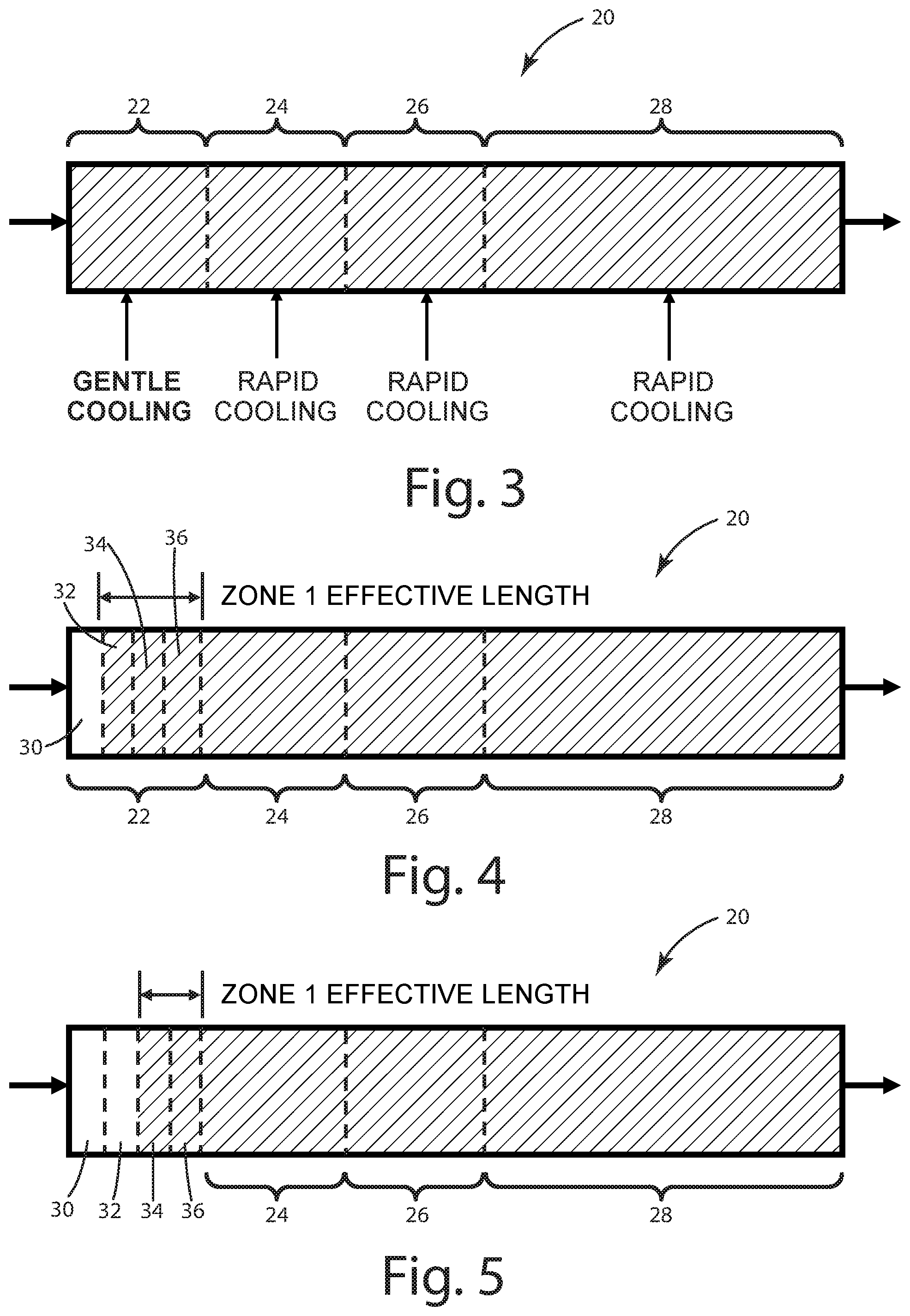
[0015] FIG. 3 is a schematic illustration of the metal extrusion quench system of the present invention.
[0016] FIG. 4 is a schematic illustration of the quench system in which three subzones of the entry zone is activated.
[0017] FIG. 5 is a schematic illustration of the quench system in which two subzones of the entry zone are activated.
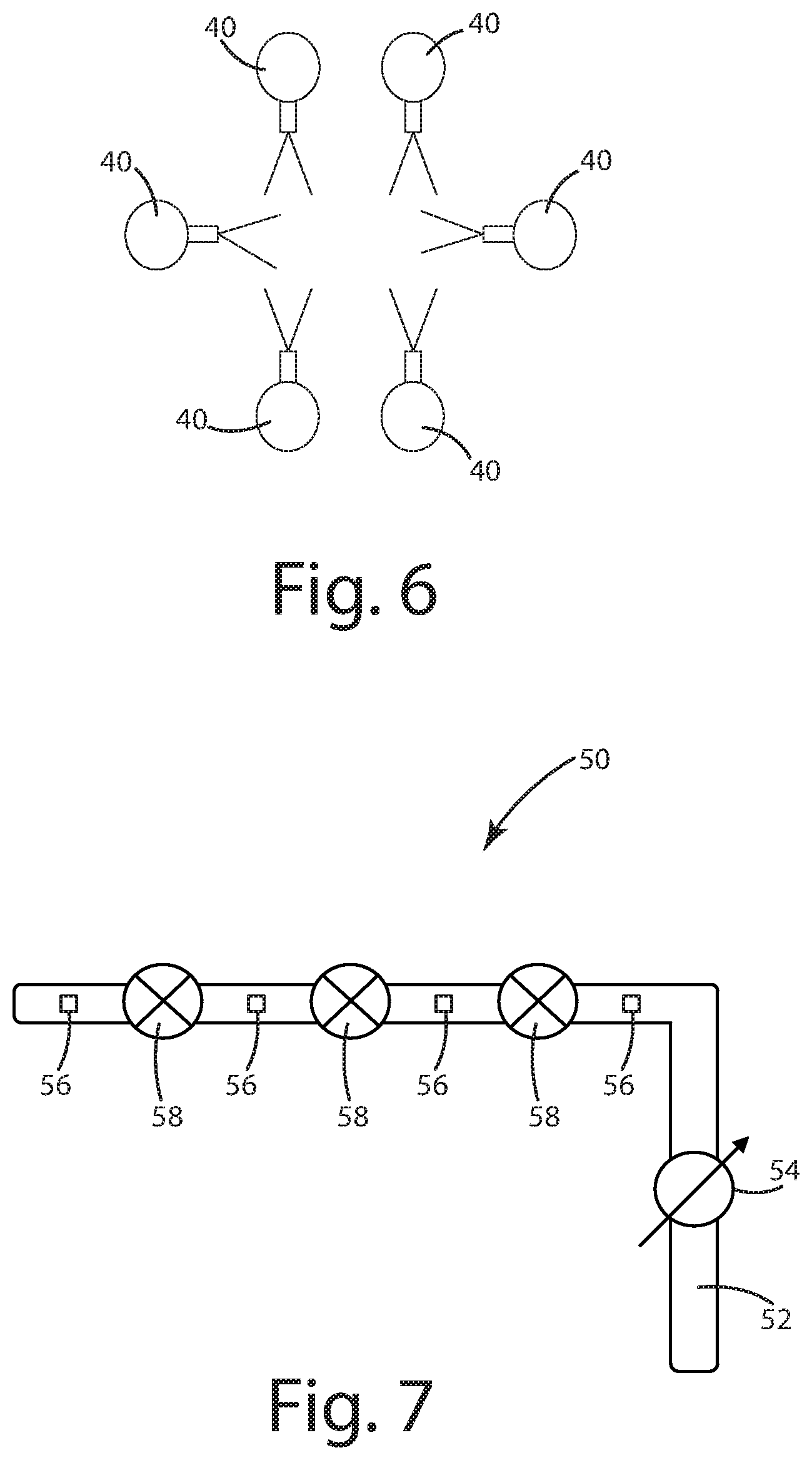
[0018] FIG. 6 is a schematic illustration of the quench heads within a single subzone of the entry zone.
[0019] FIG. 7 is a schematic illustration of a water supply arrangement for controlling water flow to the quench heads within the subzones of the entry zone.
DESCRIPTION OF THE CURRENT EMBODIMENT
[0020] Before the embodiments of the invention are explained, it is to be understood that the invention is not limited to the details of operation or to the details of construction; and the arrangement of the components set forth in the following description or illustrated in the drawings. The invention may be implemented in various other embodiments and may be practiced or carried out in alternative ways not expressly disclosed herein.
[0021] In addition, it is to be understood that the phraseology and terminology used herein are for the purpose of description and should not be regarded as limiting. The use of "including" and "comprising" and variations thereof encompasses the items listed thereafter and equivalents thereof as well as additional items and equivalents thereof. Further, enumeration may be used in the description of various embodiments. Unless otherwise expressly stated, the use of enumeration should not be construed as limiting the invention to any specific order or number of components. Nor should the use of enumeration be construed as excluding from the scope of the invention any additional steps or components that might be combined with or into the enumerated steps or components. Any reference to claim elements as "at least one of X, Y and Z" is meant to include any one of X, Y or Z individually, and any combination of X, Y and Z, for example, X, Y, Z; X, Y; X, Z; and Y, Z.
[0022] Directional terms, such as "vertical," "horizontal," "top," "bottom," "upper," "lower," "inner," "inwardly," "outer" and "outwardly," are used to assist in describing the invention based on the orientation of the embodiments shown in the illustrations. The use of directional terms should not be interpreted to limit the invention to any specific orientation(s).
[0023] A C-curve for aluminum alloy 6061 is illustrated in FIGS. 1 and 2 and generally designated 10. The C-curve 10 is generally well known to those skilled in the art. C-curves, also known as time-temperature-property (TTP) curves, are published by aluminum suppliers. Each alloy has a unique C-curve. A C-curve graphically depicts the correlation between the temperature of the alloy and the precipitation of magnesium silicide (Mg2Si and also known as Mag-silicide).
[0024] The pre-critical temperature range is illustrated by the single-headed arrow 12 in FIG. 1. The pre-critical temperature range includes all temperatures down to approximately 820.degree. F. Magnesium silicide precipitation within the alloy develops relatively slowly in this range. Accordingly, the quenching rate within this range is relatively unimportant to the development of corrosion.
[0025] When in the pre-critical temperature range 12, the metal extrusion may be relatively easily distorted, for example, by high-impact quenching water. Distortion may be reduced in one of two ways. First, distortion may be reduced by reducing the quench rate. Second, distortion may be reduced by increasing the yield strength of the profile by reducing the temperature of the extrusion.
[0026] The critical temperature range is illustrated by the double-headed arrow 14 in FIG. 2. This range includes the temperatures between approximately 680.degree. F. and approximately 820.degree. F. As noted above, Mag-silicide precipitation within the alloy develops relatively quickly in this range. Accordingly, the quenching rate within this range preferably is relatively aggressive to move the extrusion temperature through this range relatively quickly.
[0027] The present invention discovers, and takes advantage of, the reality that the rate at which the temperature of the extrusion is reduced (i.e. quenched) should depend on the temperature of the extrusion as it moves through the quenching process. The cooling rate of the extrusion will vary according to the extrusion speed and the extrusion geometry, and there can be no single location in the quench at which the critical temperature is reached for all shapes and speeds. The present invention therefore provide a balance of 1) preventing shock cooling in the pre-critical temperature range and 2) cooling as rapidly as possible across the critical temperature range. For example, one aluminum ingot supplier suggests quench rates of 80.degree. F. per second through the critical temperature range.
[0028] The C-curve illustrated in FIGS. 1 and 2 is illustrative for a particular aluminum alloy. However, the present invention is not dependent on any particular metal, any particular alloy, or any particular C-curve.
[0029] FIG. 3 schematically illustrates a quench system constructed in accordance with a current embodiment of the invention. The aluminum extrusion profile (not shown) moves through the quench system 20 from left to right as viewed in the Figures. The quench system 20 includes a first zone or an entry zone 22, a second zone 24, a third zone 26, and a fourth zone 28. Different quenching may be implemented in each of the zones 22-28 to achieve different quenching rates. For example, the quench system 20 implements relatively gentle quenching in the entry zone 22 and relatively aggressive and/or rapid quenching in zones 24-28.
[0030] FIG. 4 shows the entry zone 22 as a sequence of four sequential subzones 30, 32, 34, and 36. The physical length of the entry zone 22 is the combined length of the subzones 30-36. Each of the subzones 30-36 is adapted to provide mist quenching within the subzone. In addition, the mist quenching in each of the subzones 30-36 may be independently controlled and, specifically, may be turned on or off. As is known to those skilled in the art, mist quenching provides relatively gentle and/or slow quenching. Additionally, this type of quenching reduces or even eliminates distortion of the metal extrusion.
[0031] As configured in FIG. 4, the system 20 provides mist quenching in subzones 32-36 but not in subzone 30. Consequently, the effective quench length of the entry zone 22 in this configuration is the combined lengths of the subzones 32-36.
[0032] As configured in FIG. 5, the system 20 provides mist quenching in subzones 34 and 36 but not in subzones 30 and 32. Consequently, the effective quench length of the entry zone 22 in this configuration is the combined lengths of the subzones 34 and 36.
[0033] By extension (although not specifically illustrated), the system 20 may be configured to provide quenching in subzone 36 but not in subzones 30, 32, and 34. In such a configuration, the effective quenching length of the entry zone 22 is the length of the subzone 36.
[0034] By further extension, the system 20 may be configured to provide quenching in all four subzones 30-36. In such a configuration, the effective quenching length of the entry zone 22 is the combined lengths of all four subzones 30-36.
[0035] By yet further extension, the system 20 may be configured not to provide quenching in any of the four subzones 30-36. In such a configuration, the effective quenching length of the entry zone 22 is zero.
[0036] The configuration of the system 20, and particularly the activation of quenching within the subzones 30-36, is selected to relatively slowly reduce the temperature of the metal extrusion through, or approximately through, the pre-critical temperature range of the alloy of which the metal extrusion is fabricated. Because the quenching within the entry zone 22 is relatively gentle, distortion of the metal extrusion is insignificant or even nonexistent. This enables the metal extrusion to be cooled to a condition where its yield strength is sufficient to withstand more aggressive quenching in subsequent zones 24, 26, and 28.
[0037] Relatively aggressive and/or relatively rapid cooling is provided in quenching zones 24, 26, and 28. Such cooling may be provided using techniques well known to those skilled in the art. These techniques may include the use of high-pressure and/or high-volume water as the quenching medium. Such quenching provides relatively high rates of cooling as the temperature of the metal extrusion moves through the critical temperature range, which is desired for the reasons noted above.
[0038] FIG. 6 schematically illustrates the misting heads 40 for each of the subzones 30-36. The illustration includes six misting heads 40. This number is arbitrary, and different numbers of misting heads 40 in different configurations and orientations may be provided. The misting heads 40 are arranged around the circumference of the metal extrusion to direct mist onto the extrusion. An enclosure (not shown) contains the mist within the quenching system 20.
[0039] FIG. 7 schematically illustrates a water supply arrangement 50 suitable for providing quenching water to the subzones 30-36. The arrangement 50 includes a supply pipe 52 having a master valve 54. The arrangement 50 further includes a plurality of connection points 56 and individual valves 58. Each connection point 56 may be connected to the misting heads 40 within one of the subzones 30-36. Each of the valves 54 and 58 may be controlled to allow water to flow from the supply pipe 52 to the subzones 30-36. As disclosed, water may be provided (a) to none of the subzones, (b) to subzone 36 alone, (c) to subzones 34 and 36 (see FIG. 5), (d) to subzones 32, 34, and 36 (see FIG. 3), or (e) to all of subzones 30-36. This enables quenching water to be selectively applied to the subzones 30-36 to control the effective length (or quenching length) of the entry zone 22 so as to be extendable or extensible.
[0040] The supply of quenching water to the subzones may be controlled in other ways not currently illustrated in the drawings. For example, quenching water could be supplied to each zone independently of whether or not quenching water is supplied to the other zones.
[0041] The two-step quenching provided by the present invention includes 1) a first step in which the quenching is relatively gentle and/or relatively slow in order to provide relatively slow cooling of the metal extrusion in the pre-critical temperature range and 2) a second step in which the quenching is relatively aggressive and/or relatively fast cooling through the critical temperature range. Consequently, the invention provides slow quenching where appropriate and fast quenching where appropriate depending on the temperature of the metal extrusion at any location through the quench system 20.
[0042] The above description is that of current embodiments of the invention. Various alterations and changes can be made without departing from the spirit and broader aspects of the invention as defined in the appended claims, which are to be interpreted in accordance with the principles of patent law including the doctrine of equivalents.
[0043] This disclosure is illustrative and should not be interpreted as an exhaustive description of all embodiments of the invention or to limit the scope of the claims to the specific elements illustrated or described in connection with these embodiments. For example, and without limitation, any individual element(s) of the described invention may be replaced by alternative elements that provide substantially similar functionality or otherwise provide adequate operation. This includes, for example, presently known alternative elements, such as those that might be currently known to one skilled in the art, and alternative elements that may be developed in the future, such as those that one skilled in the art might, upon development, recognize as alternatives.
[0044] Further, the disclosed embodiments include a plurality of features that are described in concert and that might cooperatively provide a collection of benefits. The present invention is not limited to only those embodiments that include all of these features or that provide all of the stated benefits, except to the extent otherwise expressly set forth in the issued claims. Any reference to claim elements in the singular, for example, using the articles "a," "an," "the" or "said," is not to be construed as limiting the element to the singular.
* * * * *
D00000
D00001
D00002
D00003
D00004
XML
uspto.report is an independent third-party trademark research tool that is not affiliated, endorsed, or sponsored by the United States Patent and Trademark Office (USPTO) or any other governmental organization. The information provided by uspto.report is based on publicly available data at the time of writing and is intended for informational purposes only.
While we strive to provide accurate and up-to-date information, we do not guarantee the accuracy, completeness, reliability, or suitability of the information displayed on this site. The use of this site is at your own risk. Any reliance you place on such information is therefore strictly at your own risk.
All official trademark data, including owner information, should be verified by visiting the official USPTO website at www.uspto.gov. This site is not intended to replace professional legal advice and should not be used as a substitute for consulting with a legal professional who is knowledgeable about trademark law.