Capsule With Recess Passageway And System For Preparing Edible Products Including Said Capsules
NABEIRO; Rui Miguel ; et al.
U.S. patent application number 16/468061 was filed with the patent office on 2020-01-16 for capsule with recess passageway and system for preparing edible products including said capsules. This patent application is currently assigned to NOVADELTA - COMERCIO E IND STRIA DE CAFES S.A.. The applicant listed for this patent is NOVADELTA - COMERCIO E IND STRIA DE CAFES S.A.. Invention is credited to Joao Andre DE FIGUEIREDO BRANCO, Jesus MEDINA MUNDT, Rui Miguel NABEIRO.
| Application Number | 20200017288 16/468061 |
| Document ID | / |
| Family ID | 61006292 |
| Filed Date | 2020-01-16 |


| United States Patent Application | 20200017288 |
| Kind Code | A1 |
| NABEIRO; Rui Miguel ; et al. | January 16, 2020 |
CAPSULE WITH RECESS PASSAGEWAY AND SYSTEM FOR PREPARING EDIBLE PRODUCTS INCLUDING SAID CAPSULES
Abstract
The present invention refers to a capsule (1) presenting at least one first construction element (2) configured in a container-like shape, and a second construction element (3) configured in a lid-like shape, adapted so as to contain an individual portion of an edible substance, whereby said second construction element (3) presents a passageway wall (4) provided as a recess region and surrounded in at least most part of respective perimeter by a weakened material region (41) provided as a reduction of thickness in at least one of the upstream and downstream sides of said passageway wall (4). The present invention further refers to a system for preparing edible products including a capsule (1), an apparatus for preparing edible products comprising at least one brewing device (10) presenting injection means (13) adapted so that exert a mechanic pressure upon the passageway wall (4) on a region of the passageway wall (4) opposite to the region of weakened material region (41).
| Inventors: | NABEIRO; Rui Miguel; (Campo Maior, PT) ; DE FIGUEIREDO BRANCO; Joao Andre; (Moscavide, PT) ; MEDINA MUNDT; Jesus; (Lisboa, PT) | ||||||||||
| Applicant: |
|
||||||||||
|---|---|---|---|---|---|---|---|---|---|---|---|
| Assignee: | NOVADELTA - COMERCIO E IND STRIA DE
CAFES S.A. Lisboa PT |
||||||||||
| Family ID: | 61006292 | ||||||||||
| Appl. No.: | 16/468061 | ||||||||||
| Filed: | December 27, 2017 | ||||||||||
| PCT Filed: | December 27, 2017 | ||||||||||
| PCT NO: | PCT/PT2017/050030 | ||||||||||
| 371 Date: | June 10, 2019 |
| Current U.S. Class: | 1/1 |
| Current CPC Class: | A47J 31/3623 20130101; A47J 31/407 20130101; B65D 85/8043 20130101; B65B 29/022 20170801; B65D 65/466 20130101 |
| International Class: | B65D 85/804 20060101 B65D085/804; B65B 29/02 20060101 B65B029/02 |
Foreign Application Data
| Date | Code | Application Number |
|---|---|---|
| Dec 29, 2016 | PT | 109813 |
Claims
1. A capsule (1) for preparing an edible product on a brewing device (10), and presenting: a first construction element (2) configured in a container-like form and adapted so as to provide a collection volume for a single portion of an edible substance, and a second construction element (3) configured in a circular lid-like form, and adapted so as to confine said collection volume of first construction element (2) and as to provide an entry flow passageway to the interior of said first construction element (2), whereby said second construction element (3) comprises a flow entry wall part (31) that presents a disk-like general with a prevailing wall thickness (e.sub.31) between two plane transversal relative to an axial axis (X) of said wall part (31), whereby said flow entry wall part (31) is provided in a rigid material, whereby said flow entry wall part (31) comprises a passageway wall (4) provided with a circular shape delimited by a first circumferential alignment and disposed centred relative to an axial axis (X) of said capsule (1), whereby said flow passageway wall (4) presents a weakened material region (41) that develops along at least most part along at least most part of said first circumferential alignment and that is adapted so that breaks under a given upstream flow pressure, said capsule (1) being characterized in that said passageway wall (4) presents a passageway wall thickness (e.sub.4) that is smaller than said prevailing wall thickness (e.sub.31), and respective weakened material region (41) is provided by means of a localized reduction of said passageway wall thickness (e.sub.4), so that results a region with a weakened thickness (e.sub.41) along said first circumferential alignment, thereby improving the opening of said passageway wall (4) when impinged by a pressurized upstream flow.
2. The capsule (1) according to claim 1, characterized in that said passageway wall (4) is provided as a reduction of said prevailing wall thickness (e.sub.31) on a region of circular shape and disposed centred relative to said entry wall part (31), and in that said weakened material region (41) is provided in a region presenting said passageway wall thickness (e.sub.4) in the proximity of a region presenting said prevailing wall thickness (e.sub.31).
3. The capsule (1) according to claim 1, characterized in that said passageway wall (4) presents a passageway wall thickness (e.sub.4) that corresponds to a thickness reduction of said prevailing wall thickness (e.sub.31) of said entry wall part (31), provided on a region of circular shape and on both sides of said entry wall part (31), so that said passageway wall (4) develops on an intercalary plane between the exterior upstream and downstream oriented surfaces of said entry wall part (31), and in that said passageway wall (4) is provided disposed closer to the upstream oriented surface than to the downstream oriented surface of said entry wall part (31).
4. The capsule (1) according to claim 1, characterized in that said passageway wall (4) is surrounded downstream by a wall that extends beyond the plane defined by the wall thickness (e.sub.3) of said entry wall part (31) so that deflects the pressurized flow through the weakened material region (41), and in that at least said downstream surrounding wall, preferentially also an upstream surrounding wall of said passageway wall (4), develop along an oblique region relative to the direction of said axial axis (X).
5. The capsule (1) according to claim 1, characterized in that said weakened material region (41) is provided along at least most part, preferentially the totality, of a circumferential perimeter and presents a first (e.sub.41) and a second (e.sub.42) weakened thickness, whereby said first weakened thickness (e.sub.41) is smaller than said second weakened thickness (e.sub.42).
6. The capsule (1) according to claim 1, characterized in that said first weakened thickness (e.sub.41) is comprised between 0.05 and 0.20, preferentially between 0.10 and 0.15, of said passageway wall thickness (e.sub.4) of said passageway wall (4).
7. The capsule (1) according to claim 1, characterized in that said weakened material region (41) corresponds to the region between a first recess provided on the upstream oriented side of said passageway wall (4), and a second recess provided on the downstream oriented side of said passageway wall (4), whereby each one of said recesses develops along a transversal direction along a circumferential alignment and develops in an axial direction so that said recesses distance, in the nearest region between themselves, in the value corresponding to said weakened thickness (e.sub.41).
8. The capsule (1) according to claim 1, characterized in that said weakened material region (41) is provided as the region between two recesses in mutually opposing sides of said flow passageway wall (4), whereby said recesses present at least one of different shape and different dimension.
9. The capsule (1) according to claim 1, characterized in that said weakened material region (41) is provided as region extending between two recesses on said passageway wall (41) that present different maximum depths relative to the surface planes of respective sides of said passageway wall (4).
10. The capsule (1) according to claim 1, characterized in that said weakened material region (41) is provided as the region extending between two recesses on said passageway wall (4) that present maximum depths that develop in different planes at least approximately parallel to said axial axis (X).
11. The capsule (1) according to claim 1, characterized in that said weakened material region (41) is provided as the region between two recesses disposed in opposing side of said passageway wall (4) and presenting at least one oblique surface relative to the direction of said axial axis (X), whereby in the region closest to each other said recesses configure two surfaces oblique relative to said axial axis (X), and that develop at least approximately parallel along a preferential rupture extension that presents said weakened thickness (e.sub.41) and that develops in oblique manner relative to the direction of said axial axis (X).
12. The capsule (1) according to claim 1, characterized in that said weakened material region (41) is provided as the region between two recesses on opposite sides of said passageway wall (4), whereby recesses disposed on the upstream side develop at least partially in a more proximal region than recesses disposed on the downstream oriented side, with reference to said axial axis (x).
13. The capsule (1) according to claim 1, characterized in that said weakened material region (41) presents a first weakened thickness (e.sub.41) that develops along an arch of circumference comprised between 348.degree. and 325.degree., preferentially between 345.degree. and 328.degree..
14. The capsule (1) according to claim 1, characterized in that presents at least one of: further presents a recess region (5) provided on the upstream oriented side of said flow entry wall part (31), whereby said recess region (5) develops from a second circumferential alignment in the proximity of said passageway wall (4) and so that defines an intercalary region (6) between said recess region (5) and said passageway wall (4), whereby said recess region (5) presents a recess wall thickness (e.sub.5) that is smaller than the prevailing wall thickness (e.sub.31), and bigger than the passageway wall thickness (e.sub.4) of said passageway wall (4), so that said passageway wall (4) is deflected when the pressurized flow breaks said weakened material region (41), an intercalary region (6) that presents an intercalary wall thickness (e.sub.6) that is bigger than the passageway wall thickness (e.sub.4) of said passageway wall (4) and bigger than the wall thickness of said recess wall (e.sub.5) of said recess region (5), preferentially is at least approximately similar to said prevailing wall thickness (e.sub.31), thereby improving the transmission of structural resistance from said recess region (5) and into said weakened material region (41).
15. A system for preparing edible products comprising: a capsule (1) adapted for containing a single portion of an edible substance, in particular a capsule (1) according to claim 1, and an apparatus for preparing edible products based upon said capsule (1) and including at least one brewing device (10) that presents two actuation parts (11, 12), whereby said capsule (1) presents an upstream oriented wall part (31) that presents a passageway wall (4) of circular shape and disposed centred relative to an axial axis (X) of said capsule (1), and successively surrounded by an intercalary region (6) and a recess region (5), whereby said actuation parts (11, 12) are adapted so as to collect said capsule (1), and at least one of said actuation parts (11, 12) can be moved relative to the other so as to engage with the exterior envelope of said capsule (1), whereby an upstream actuation part (11) comprises injection means (13) adapted for impinging a pressurized fluid flow upon said passageway wall (4) provided on an upstream side of said capsule (1), whereby a downstream actuation part (12) comprises discharge means adapted for collecting a beverage from the downstream side of said capsule (1), said system being characterized in that said injection means (13) are provided as a projection developing downstream and adapted so that exerts a mechanic pressure upon part of said passageway wall (4) in the proximity of said weakened material region (41), so that said passageway wall (4) swivels downstream around a region of said passageway wall (4) opposite to said weakened material region (41) as a result of said mechanic pressure.
Description
FIELD OF THE INVENTION
[0001] The present invention refers to the field of the capsules for preparing edible products including aromatic beverages, such s for example espresso coffee, tea and similar.
[0002] The present invention further refers to a system for preparing edible products based upon capsules.
BACKGROUND OF THE INVENTION
[0003] The prior art includes several solutions relating to systems for preparing beverages, such as for example machines for preparing beverages including espresso coffee, tea and similar, based upon capsules containing a single portion of edible substance and provided so that are collected inside of a brewing device. Said brewing device is adapted so as to inject a pressurized fluid flow through an upstream side of capsule, and to collect the resulting beverage from a downstream side of capsule.
[0004] In particular in the case of capsules provided in a substantially rigid material and construction structure, despite being retained by means of pressured engagement inside of a respective brewing device, this type of capsules can slip a direction transversal to the prevailing flow direction, notably in a rotation movement around its axial axis, in particular in case that the pressurized water injection is not done by means of penetration of the capsule envelope. In fact, in the case of brewing devices with multiple pressurized water injection outlets, there is the need to ensure that a capsule of this type is retained in reliable manner, and eventually positioned on a given angular position, inside of a respective brewing device.
[0005] The document EP 2287090 B1 discloses a capsule comprising a container part with a base wall that presents a structure that forms a reduced thickness of entry wall of the pressurized fluid. In particular, said structure forms a continuous annular recess portion of radius R1 where there is provided a plurality of injection holes.
[0006] The document EP 2394932 B1 discloses a capsule similar to that of the aforementioned document, whereby in this case there is provided a weakened material region designed such that breaks at least partially under the pressure of a pressurized liquid. Moreover, the body of the capsule is made of plastic or from a plastic based material.
[0007] The document EP 2560897 B1 discloses a capsule comprising a container part with a base wall that presents a weakened material zone that defines a wall part that can be broken, and a portion of greater thickness of said base wall around which the wall part that can be broken turns.
[0008] The document EP 2757057 A1 discloses a capsule that presents a groove that surrounds a central region that presents at least perforation zone with perforations that provide an entry of hot water into the interior of capsule.
[0009] The document WO 2015/002562 A1 submitted by the author of the present application discloses a capsule comprising a lid-like element that presents at least one engagement groove disposed such that is surrounded by, or itself surrounds, a zone of said second construction element adapted for fluid passage.
[0010] General Description of the Invention
[0011] The objective of the present invention is to provide a capsule in a substantially rigid construction, for collection of a single portion of an edible substance, in particular adapted for preparing edible products, including beverages, inside of a respective brewing device, and that provides sufficient oxygen barrier and a reliable opening to pressurized flow through a respective upstream oriented wall and presenting a weakened material region.
[0012] This objective is solved by means of a capsule according to claim 1.
[0013] In particular, this objective is attained by means of a capsule that presents a lid-like construction element, presenting a wall part and a flow passageway wall provided as a recess region of circular shape in the central region of said wall part and presenting a smaller wall thickness, whereby said passageway wall is delimited along at least part of a circumferential alignment by a weakened material region adapted so that said passageway wall breaks in this zone and swivels around part of said circumferential alignment.
[0014] The capsule according to the invention comprises a first construction element configured in a container-like form, and a second construction element configured in a lid-like form and adapted for entry of a pressurized fluid preferentially without holing of a respective exterior envelope, and adapted for joint assembly so as to provide an interior volume for collection of a portion of at least one edible substance, including coffee, tea and similar.
[0015] It is preferred when the upstream oriented surface of capsule presents a recess region surrounding the passageway wall and an intercalary region between these.
[0016] It is preferred when said recess region develops from a second circumferential alignment in the proximity of said passageway wall and so that results an intercalary region between said recess region and said passageway wall, whereby said recess region presents a recess wall thickness (e.sub.5) that is smaller than the prevailing wall thickness (e.sub.31), and bigger than the passageway wall thickness (e.sub.4) of said passageway wall, so that structurally reinforces the surrounding region of said passageway wall and provides retention surfaces for an engagement element provided on said brewing device.
[0017] It is preferred when at least most part, preferentially the totality, of recess wall thickness (e.sub.5) of said recess region develops between transversal planes in the proximity downstream of the transversal planes that delimit the passageway wall thickness (e.sub.4) of said passageway wall, so that at least most part of said recess wall thickness (e.sub.5) is provided downstream of said passageway wall thickness (e.sub.4).
[0018] It is preferred when said passageway wall is delimited by a first circumferential alignment that presents a first diameter (d.sub.1) smaller than 0.35 times the diameter (d) of said flow entry wall part.
[0019] It is preferred when said recess region is delimited on a respective distal side by a circumferential alignment presenting a second diameter (d.sub.2), whereby said second diameter (d.sub.2) is at least 1.2 times bigger, preferentially at least 1.4 times bigger, and at most 2.5 times bigger, preferentially at most 2 times bigger than said first diameter (d.sub.1).
[0020] It is preferred when the radial extension of said recess region is at least approximately similar, preferentially bigger than 0.8 times and smaller than 1.2 times the radial extension of said intercalary region.
[0021] It is preferred when said recess region presents a substantially polygonal transversal section defining at least three interior surfaces, preferentially five interior surfaces, and presenting a depth between 1 and 3 mm, preferentially between 1.5 and 2.5 mm, relative to the exterior surface of said second construction element, and a radial dimension between 1 and 3 mm, preferentially between 1.5 and 2.5 mm.
[0022] It is preferred when said intercalary region presents an intercalary wall thickness (e.sub.6) that is bigger than the passageway wall thickness (e.sub.4) of said passageway wall and bigger than the recess wall thickness (e.sub.5) of said recess region, preferentially is at least approximately similar to said prevailing wall thickness (e.sub.31), thereby structurally reinforcing the region surrounding said weakened material region and providing a support surface to a sealing element provided on said brewing device.
[0023] It is preferred when said intercalary region presents an intercalary wall thickness (e.sub.6) that develops between planes transversal to the axial direction upstream and downstream of the transversal planes that delimit said passageway wall thickness (e.sub.4) and recess wall thickness (e.sub.5).
[0024] It is preferred when said intercalary region comprises a seat region that develops in the upstream oriented surface of said flow entry wall part along at least most part of the radial extension between said passageway wall and said recess region, whereby said seat region is adapted so that provides a seat surface to a sealing element provided on said brewing device.
[0025] It is preferred when said seat region presents a seat wall thickness (e.sub.61) that is bigger than the passageway wall thickness (e.sub.4) of said passageway wall, thereby improving the opening of said weakened material region as impinged by an upstream pressurized flow.
[0026] It is preferred when said seat region presents a seat wall thickness (e.sub.61) that is bigger than the recess wall thickness (e.sub.5) of said recess region, preferentially presents a wall thickness that is at least approximately similar to said prevailing wall thickness (e.sub.31).
[0027] It is preferred when said intercalary region presents a guiding projection along said first circumferential alignment so that delimits said seat region relative to said passageway wall, whereby said guiding projection projects beyond the upstream oriented exterior surface of said flow entry wall part, so that provides a conduction surface that is adjacent and substantially orthogonal or oblique relative to the surface provided by said seat region.
[0028] It is preferred when said passageway wall presents a projection element that develops upstream, whereby said projection element develops along an extension beyond the plane defined the upstream oriented surface of said flow entry wall part, so that can be impinged by a flow injection part of said brewing device.
[0029] It is preferred when said projection element is provided only on one side of said passageway wall relative to said axial axis (X), preferentially in the proximity of perimeter of said passageway wall.
[0030] It is preferred when said projection element develops along an extension comprised between 10 to 40.degree., preferentially between 15 and 35.degree., of the circumferential alignment that develops in at least approximately parallel manner relative to the circumferential alignment defined by the exterior limit of said passageway wall.
[0031] It is preferred when said projection element is provided in the proximity of the perimeter and on the side that develops in the weakened material region presenting a smaller thickness.
[0032] Another objective of the present invention is to provide a system for preparing edible products based upon capsules, presenting capsules and a brewing device adapted so as to improve the entry of flow into said capsules, in particular opening of a passageway wall presenting a weakened material region.
[0033] This objective is solved according to claim 15.
[0034] It is preferred when said injection means are provided as a projection adapted so that at least part, preferentially at least most part of respective extension of projection develops inside the recess formed by said passageway wall on said flow entry wall part, when said brewing device is in a closed position.
[0035] It is preferred when said injection means are provided as a projection adapted so that exerts a mechanic pressure, preferentially in asymmetric manner, upon part of said passageway wall, in asymmetric manner relative to the form thereof and on a side opposite to that of a respective weakened material region.
[0036] It is preferred when said injection means are provided as a projection adapted so that exerts a mechanic pressure upon a projection element provided so that extends upstream and above and higher than said passageway wall, preferentially higher than said flow entry wall part.
[0037] An associated objective is to disclose a system that provides an improved concentration of pressurized flow on a passageway wall presenting a weakened material region.
[0038] It is preferred when said upstream actuation part presents an engagement element provided as a protuberance that develops at a distance from said injection means and adapted so that engages on said recess region provided on said flow entry wall part, so as to thereby retain said capsule with relation to a sealing element provided so that surrounds said injection means.
[0039] It is preferred when said engagement element is provided so that develops along an extension of arch of circumference that is smaller than 20.degree., preferentially smaller than 15.degree., and bigger than 3.degree., preferentially bigger than 5.degree..
[0040] It is preferred when said sealing element is provided with a ring shape and adapted so that sits on the seat region of said intercalary region between said passageway wall and recess region.
[0041] It is preferred when said sealing element is provided as a projection that develops along the axial direction with a smaller extension than the extension of said engagement element.
DESCRIPTION OF THE FIGURES
[0042] The present invention shall be hereinafter explained in greater detail based upon the description of preferred embodiments thereof and the Figures attached.
[0043] The Figures show, in simplified schematic representations:
[0044] FIG. 1: plan view (top) and side cut (bottom) of a capsule (1) according to prior art;
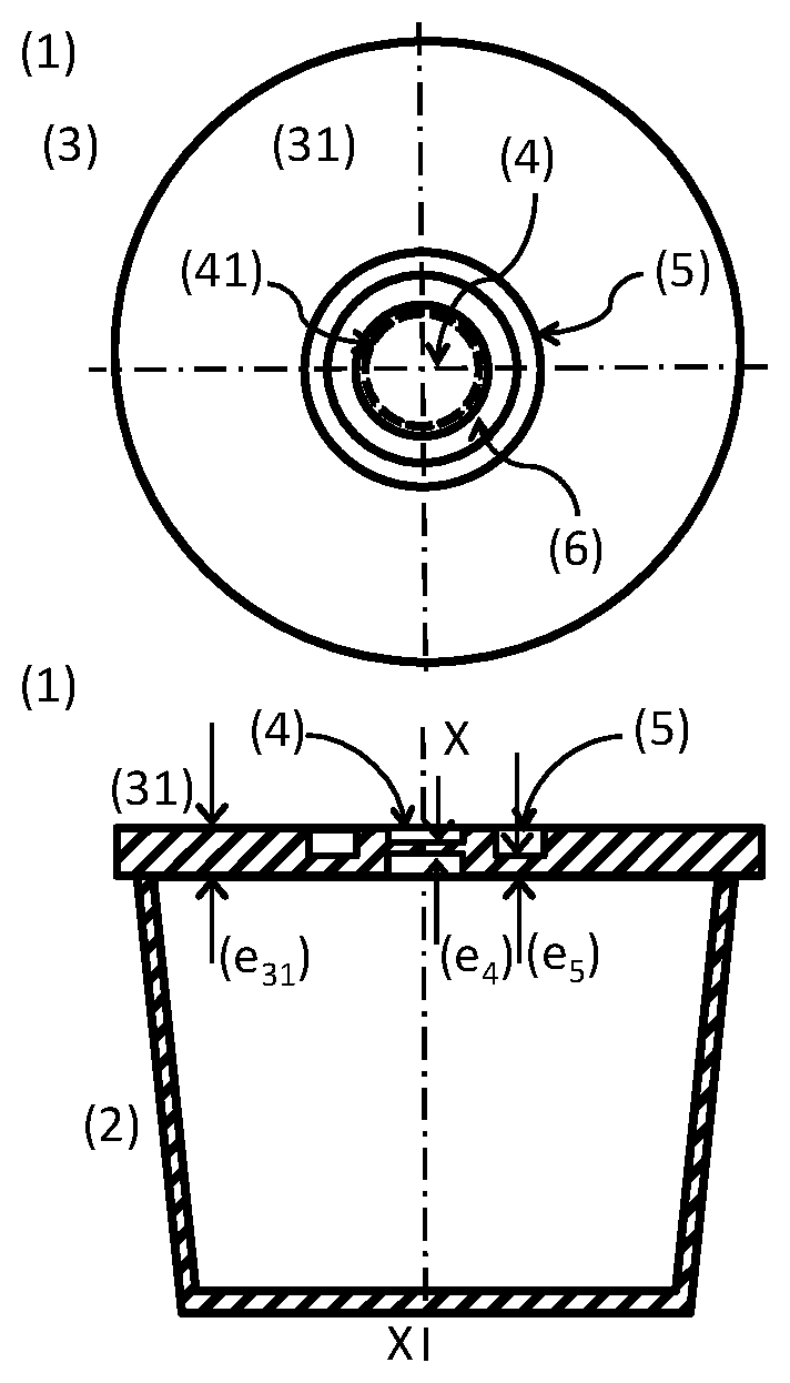
[0045] FIG. 2: plan view (top) and side cut (bottom) of a capsule (1) according to present invention;
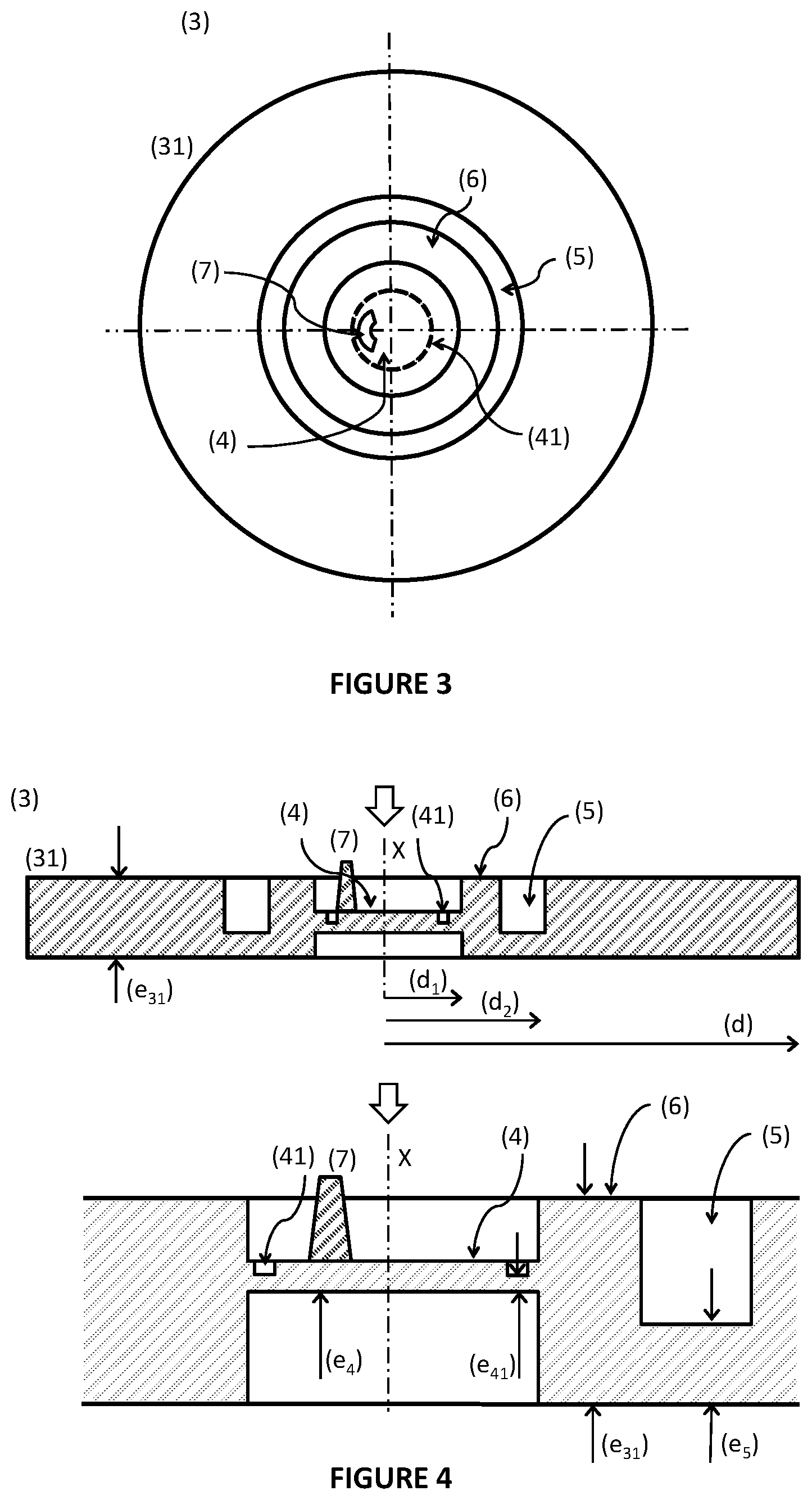
[0046] FIG. 3: plan view of a first embodiment of a second construction element (3) in a capsule (1) according to the invention;
[0047] FIG. 4: side cut view (top) and respective detail of central region (bottom) of second construction element (3) according to FIG. 3;
[0048] FIG. 5: plan view of a second embodiment of second construction element (3) in a capsule (1) according to the invention;
[0049] FIG. 6: side cut view (top) and respective detail of central region (bottom) of second construction element (3) according to FIG. 5;
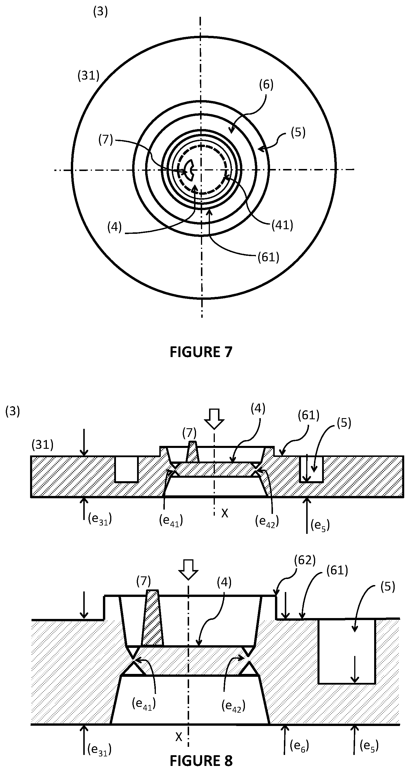
[0050] FIG. 7: plan view of a third embodiment of second construction element (3) in a capsule (1) according to the invention;
[0051] FIG. 8: side cut view (top) and respective detail of central region (bottom) of second construction element (3) according to FIG. 7;
[0052] FIG. 9: plan view of a fourth embodiment of second construction element (3) in a capsule (1) according to the invention;
[0053] FIG. 10: side cut view (top) and respective detail of central region (bottom) of second construction element (3) according to FIG. 9;
[0054] FIG. 11: side cut views of a brewing device (10) open (left-hand side) and closed (right-hand side) and capsule (1) according to the present invention;
[0055] FIG. 12: front view of the upstream actuation part (11) of a brewing device (10) comprised in a system according to the invention.
DETAILED DESCRIPTION OF THE INVENTION
[0056] As can be observed in FIG. 1, a capsule of the type of capsule (1) includes a first construction element (2) configured in a container-like shape and a second construction element (3) configured in a lid-like shape. Said first and second construction elements (2, 3) are provided as substantially rigid, for example in a plastic material, and adapted for joint assembly along a common central axis (X) of said capsule (1), thereby providing an interior volume adapted for collection of a single portion of at least one edible substance, such as for example roasted ground coffee beans.
[0057] Optionally, there can be provided a recess region (5) on the upstream-oriented side, of annular shape and eventually presenting a weakened material region.
[0058] As can be observed in FIG. 2, in the case of a capsule (1) according to the present invention, a second construction element (3) presents a flow entry wall part (31) that presents a disk-like general shape and a passageway wall (4) provided as a region that is recessed relative to the exterior surface planes of said flow entry wall part (31).
[0059] In the case of a first embodiment of said capsule (1), said passageway wall (4) presents a passageway wall thickness (e.sub.4) that corresponds to a reduction of thickness of the prevailing wall thickness (e.sub.31) of said flow entry wall part (31), provided in a region of circular shape and on both sides of said flow entry wall part (31), so that said passageway wall (4) develops in a intercalary plane between the exterior surfaces oriented upstream and downstream of said flow entry wall part (31). Moreover, it is preferred when at least the downstream surrounding walls, preferentially also the upstream surrounding walls of said passageway wall (4), develop along an oblique direction relative to the direction of said axial axis (X).
[0060] Said passageway wall part (4) presents a weakened material region (41) that develops along at least most part of said first circumferential alignment and that is adapted so that breaks under a given upstream pressure.
[0061] The second construction element (3) of said capsule (1) further presents a recess region (5) provided on the upstream oriented side of said flow entry wall part (31), whereby said recess region (5) develops from a second circumferential alignment in the proximity of said passageway wall (4) and so that results an intercalary region (6) between said recess region (5) and said passageway wall (4), whereby said recess region (5) presents a recess wall thickness (e.sub.5) that is smaller than the prevailing wall thickness (e.sub.31), and bigger than the passageway wall thickness (e.sub.4) of said passageway wall (4), so that said passageway wall (4) is deflected under the pressurized flow so that breaks said weakened material region (41).
[0062] The second construction element (3) of said capsule (1) further presents an intercalary region (6) that presents an intercalary wall thickness (e.sub.6) that is bigger than the passageway wall thickness (e.sub.4) of said passageway wall (4) and bigger than the recess wall thickness (e.sub.5) of said recess region (5), preferentially is at least approximately similar to said prevailing wall thickness (e.sub.31), thereby improving the transmission of structural resistance from said recess region (5) and to said weakened material region (41).
[0063] According to an inventive aspect of a capsule (1) according to the present invention, said passageway wall (4) presents a passageway wall thickness (e.sub.4) that is smaller than said prevailing wall thickness (e.sub.31), and respective weakened material region (41) is provided by means of localized reduction of said passageway wall thickness (e.sub.4), so that results a region of weakened thickness (e.sub.41) along said first circumferential alignment, thereby improving the opening of said passageway wall (4) when impinged by an upstream pressurized flow--see FIGS. 3 and 4.
[0064] Moreover, said passageway wall (4) is provided as a reduction of said prevailing wall thickness (e.sub.31) in a region of circular shape and centred relative to the centre (X) of said flow entry wall part (31), and said weakened material region (41) is provided between said prevailing wall thickness (e.sub.31) and said passageway wall thickness (e.sub.4).
[0065] According to an inventive aspect, said flow passageway wall (4) presents a projection element (7) that extends upstream, whereby said projection element (7) develops along an extension beyond the plane defined by the upstream oriented surface of said entry wall part (31), so that said projection element (7) can be impinged by a flow injection part (13) of said brewing device (10) as the latter moves in the closing movement, and thereby generates a deflection moment upon said weakened material region (41)--see FIGS. 3 to 10.
[0066] It is thus provided an additional element of mechanic pressure upon the weakened material region (41) of said passageway wall (4), thereby contributing to a reliable opening thereof.
[0067] It is preferred when said projection element (7) is provided only on one side of said flow passageway wall (4) relative to said axial axis (X), preferentially in the proximity of perimeter of said flow passageway wall (4).
[0068] It is further preferred when said projection element (7) develops along an angular extension comprised between 10 to 40.degree., preferentially between 15 to 35.degree., of a circumferential alignment that develops in at least approximately manner relative to the circumferential alignment defined by the exterior limit of said passageway wall (4).
[0069] It is further preferred when said projection element (7) is provided in the proximity of perimeter and on one side where develops said weakened material region (41) presenting a smaller wall thickness.
[0070] According to a preferred embodiment--see FIGS. 3 to 10--it is preferred when said passageway wall (4) presents a passageway wall thickness (e.sub.4) that corresponds to a thickness reduction of prevailing wall thickness (e.sub.31) of said flow entry wall part (31), provided in a region of circular shape and on both side of said flow entry wall part (31), so that said passageway wall (4) develops in an intercalary plane between upstream and downstream oriented exterior surfaces of said flow entry wall part (31).
[0071] It is further preferred when said passageway wall (4) is provided closer to the upstream oriented surface than from the downstream oriented surface of said flow entry wall part (31).
[0072] According to an inventive aspect--see FIGS. 7 to 10 --said weakened material region (41) is provided as the region between two recesses in opposite sides of said passageway wall (4), whereby said recesses presents at least one of different shape and different dimension relative to the remaining passageway wall (41).
[0073] It is preferred when said weakened material region (41) is provided as the region between two recesses in opposite sides of said passageway wall (4), developing along a circumferential alignment of at least approximately similar dimension, whereby said recesses distant from each other in the closest region between each other in the value corresponding to said weakened thickness (e.sub.41).
[0074] It is preferred when said weakened material region (41) is provided as the region between two recesses in opposite sides of said passageway wall (4), whereby said recesses presents different depths relative to the surface planes of the respective sides of said passageway wall (4), and said maximum depths develop in different projections along planes parallel to said axial axis (X).
[0075] It is further particularly preferred when said weakened material region (41) is provided as the region between two recesses in opposite sides of said passageway wall (4), whereby the recesses disposed on the upstream side develop at least partially on a more proximal region than the recesses disposed on the upstream oriented side, with reference to said axial axis (x) of said passageway wall (4).
[0076] According to another inventive aspect--see FIGS. 9 to 10--, said weakened material region (41) is provided as the region between two recesses in opposite sides of said passageway wall (4) and presenting at least one oblique surface relative to the direction of said axial axis (X), whereby in the region closest to each other said recesses configure two surfaces oblique relative to the direction of said axial axis (X), and that develop at least approximately parallel along a preferential rupture extension that presents said weakened thickness (e.sub.41) and develops in oblique manner relative to the direction of said axial axis (X).
[0077] It is preferred when said passageway wall (4) is surrounded downstream by a wall that extends beyond the plane defined by the wall thickness (e.sub.3) of said flow entry wall part (31) so that deflects the pressurized flow through the weakened material region (41), and in that at least said downstream surrounding wall, preferentially also an upstream surrounding wall of said passageway wall (4), develop along an oblique direction relative to the direction of said axial axis (X).
[0078] It is preferred when said weakened material region (41) is provided along at least most part, preferentially the totality, of a circumferential perimeter and presents a first (e.sub.41) and a second (e.sub.42) weakened thickness, whereby said first weakened thickness (e.sub.41) is smaller than said second weakened thickness (e.sub.42).
[0079] It is further preferred when said first weakened thickness (e.sub.41) develops along a bigger extension than said second weakened thickness (e.sub.42).
[0080] FIG. 11 represents a system according to the present invention comprising a capsule (1) adapted for containing an edible substance, for example roasted and ground coffee beans, and a brewing device (10) adapted for being part of an apparatus for preparing edible products, such as for example a coffee machine.
[0081] Said brewing device (10) presents an upstream part (11) adapted for injection of pressurized flow, and a downstream part (12) adapted for collection of the resulting edible product.
[0082] As one can observe in FIG. 12, the upstream part (11) presents, along the radial direction, injection means (13), a sealing element (14) provided in the proximity of said injection means (13) and further an engagement element (15) provided adjacent to said sealing element (14).
[0083] According to an inventive aspect, said injection means (13) are provided as a projection extending downstream and adapted so that exerts a mechanic pressure upon part of said passageway wall (4) in the proximity of the weakened material region (41), so that said passageway wall (4) swivels downstream around a region of said passageway wall (4) that is opposite to said weakened material region (41) as a result of said mechanic pressure--see drawing on the right-hand side of FIG. 11.
[0084] Moreover, said injection means (13) are provided as a projection adapted so that at least part, preferentially at least most part of respective extension of projection develops inside of the recess formed by said passageway wall on said flow entry wall part (31), when the brewing device (10) is in a closed position.
[0085] It is preferred when said injection means (13) are provided as a projection adapted so that exerts a mechanic pressure, preferentially in asymmetric manner, upon part of said passageway wall (4).
[0086] It is further preferred when said injection means (13) are provided as a projection adapted so that exerts a mechanic pressure upon a projection element (7) provided so that extends upstream above and higher than said passageway wall (4)--see FIGS. 3 to 10.
Lisbon, Dec. 27, 2017
* * * * *
D00000
D00001
D00002
D00003
D00004
D00005
D00006
XML
uspto.report is an independent third-party trademark research tool that is not affiliated, endorsed, or sponsored by the United States Patent and Trademark Office (USPTO) or any other governmental organization. The information provided by uspto.report is based on publicly available data at the time of writing and is intended for informational purposes only.
While we strive to provide accurate and up-to-date information, we do not guarantee the accuracy, completeness, reliability, or suitability of the information displayed on this site. The use of this site is at your own risk. Any reliance you place on such information is therefore strictly at your own risk.
All official trademark data, including owner information, should be verified by visiting the official USPTO website at www.uspto.gov. This site is not intended to replace professional legal advice and should not be used as a substitute for consulting with a legal professional who is knowledgeable about trademark law.