Aircraft Turbine With Counter-rotating Propellers
Dorfner; Matthias ; et al.
U.S. patent application number 16/335840 was filed with the patent office on 2020-01-16 for aircraft turbine with counter-rotating propellers. The applicant listed for this patent is SIEMENS AKTIENGESELLSCHAFT. Invention is credited to Matthias Dorfner, Korbinian Petermaier.
| Application Number | 20200017230 16/335840 |
| Document ID | / |
| Family ID | 57136822 |
| Filed Date | 2020-01-16 |


| United States Patent Application | 20200017230 |
| Kind Code | A1 |
| Dorfner; Matthias ; et al. | January 16, 2020 |
AIRCRAFT TURBINE WITH COUNTER-ROTATING PROPELLERS
Abstract
The invention relates to an aircraft turbine having counter-rotating propellers and a primary drive, the noise development of which is significantly reduced with respect to aircraft turbines which have a primary drive based on the internal combustion principle. The invention relates to an aircraft turbine having counter-rotating propellers and a primary drive, the primary drive of which is based on the electric drive principle.
| Inventors: | Dorfner; Matthias; (Munchen, DE) ; Petermaier; Korbinian; (Munchen, DE) | ||||||||||
| Applicant: |
|
||||||||||
|---|---|---|---|---|---|---|---|---|---|---|---|
| Family ID: | 57136822 | ||||||||||
| Appl. No.: | 16/335840 | ||||||||||
| Filed: | September 23, 2016 | ||||||||||
| PCT Filed: | September 23, 2016 | ||||||||||
| PCT NO: | PCT/EP2016/072683 | ||||||||||
| 371 Date: | March 22, 2019 |
| Current U.S. Class: | 1/1 |
| Current CPC Class: | H02K 16/02 20130101; B64D 27/24 20130101; F02K 5/00 20130101; B64D 35/02 20130101; B64C 11/48 20130101; Y02T 50/60 20130101; B64D 35/06 20130101 |
| International Class: | B64D 35/06 20060101 B64D035/06; B64D 35/02 20060101 B64D035/02; H02K 16/02 20060101 H02K016/02 |
Claims
1. An aircraft turbine comprising: counter-rotating propellers; and a primary drive; wherein the primary drive uses an electric drive principle.
2. The aircraft turbine of claim 1, wherein the primary drive is configured as a rotationally symmetrical synchronous motor comprising a tooth coil winding that includes a first rotor with a first number of poles for the first propeller, and a second rotor with a second number of poles for the second propeller; wherein the first rotor is an internal rotor and the second rotor is an external rotor; wherein the first number of poles and the second number of poles differ from each other; wherein the first rotor and the second rotor are each mounted so that the first rotor and the second rotor rotate independently with respect to each other; and wherein the first rotor and the second rotor each include a shaft-and-flange arrangement for attachment of each of the two propellers.
3. The aircraft turbine of claim 2, wherein the rotationally symmetrical synchronous motor is configured to be permanently excited.
4. The aircraft turbine of claim 1, wherein the counter-rotating propellers rotate at different speeds as a function of a drive frequency.
5. The aircraft turbine of claim 2, the counter-rotating propellers rotate at different speeds as a function of a drive frequency.
Description
CROSS REFERENCE TO RELATED APPLICATIONS
[0001] This present patent document is a .sctn. 371 nationalization of PCT Application Serial Number PCT/EP2016/072683, filed Sep. 23, 2016, designating the United States, which is hereby incorporated in its entirety by reference.
FIELD
[0002] Embodiments relate to aircraft turbines with counter-rotating propellers.
BACKGROUND
[0003] Aircraft turbines with counter-rotating propellers are known, the primary drive of which is based on the internal combustion principle.
[0004] In a simple propeller arrangement, a swirl is imparted to the air that flows through the propeller, that reduces the efficiency of the propeller. A second counter-rotating propeller attached behind the first propeller reduces this swirl and consequently increases the efficiency of the propeller. However, significant noise generation is entailed by the principle of counter-rotating propellers.
SUMMARY AND DESCRIPTION
[0005] The scope of the present invention is defined solely by the appended claims and is not affected to any degree by the statements within this summary. The present embodiments may obviate one or more of the drawbacks or limitations in the related art.
[0006] Embodiments provide an aircraft turbine with counter-rotating propellers that includes reduced noise generation.
[0007] The aircraft turbine with counter-rotating propellers includes a primary drive that is based on the electric drive principle instead of the internal combustion principle.
[0008] Electric drives are significantly quieter than internal combustion drives, with the result that the noise generation of the aircraft turbine as a whole is significantly reduced.
[0009] The primary drive is configured as a rotationally symmetrical synchronous motor with a tooth coil winding, with a first rotor with a first number of poles for the first propeller, and a second rotor with a second number of poles for the second propeller. The first rotor is an internal rotor and the second rotor is an external rotor. The first number of poles and the second number of poles differ from each other. The first and the second rotor are each mounted so that the rotors can rotate independently with respect to each other. The first and the second rotor each include a shaft-and-flange arrangement for attachment of each of the two propellers.
[0010] A primary drive of this type includes a low-volume and hence quiet noise generation and is therefore suited for the drive.
[0011] Up until now, in a tooth coil motor only one dominant harmonic of the electric loading has been used. Tooth coil windings, for example, double-layer tooth coil windings, in contrast form an electric loading with multiple dominant harmonics. By choosing different suitably selected numbers of poles, two dominant harmonics are used for each of the rotors mounted so that the rotors can rotate independently of each other.
[0012] In an embodiment, the synchronous motor is configured so that it is permanently excited.
[0013] In an embodiment, the aircraft turbine is configured such that the counter-rotating propellers rotate at different speeds as a function of the drive frequency.
BRIEF DESCRIPTION OF THE FIGURES
[0014] FIG. 1 depicts a motor module in a developed view according to an embodiment.
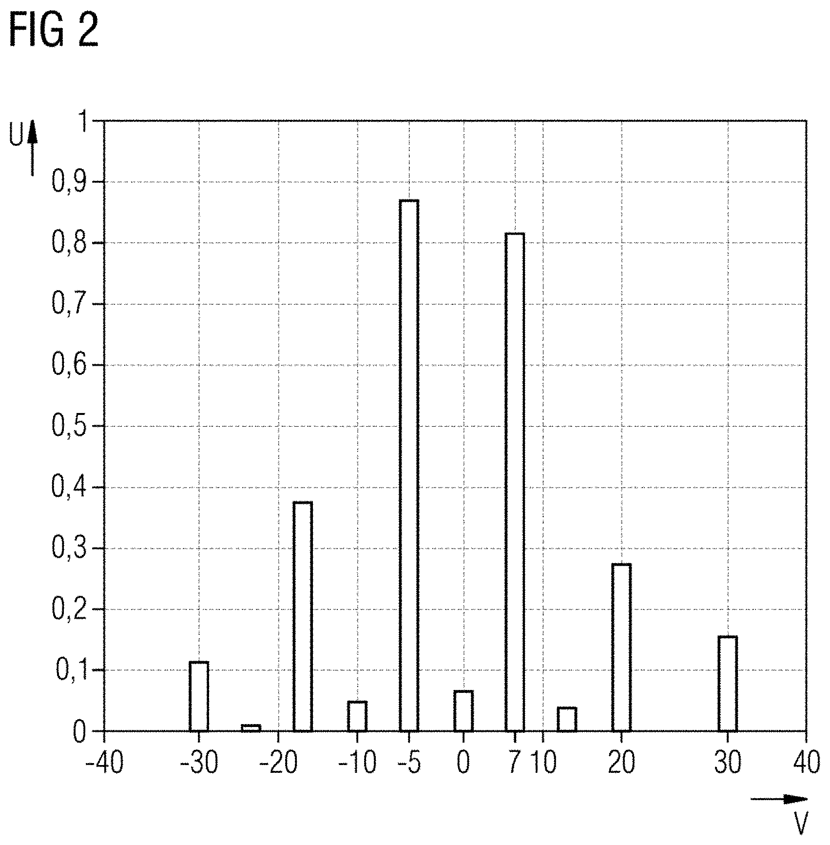
[0015] FIG. 2 depicts a diagram with winding factors of a double-layer tooth coil winding according to an embodiment.
DETAILED DESCRIPTION
[0016] FIG. 1 depicts a motor module 1, including of a belt winding in the stator II and 10 or 14 poles (tooth coils) in each rotor component III or IV. The portion of the stator II depicted has 12 tooth coils that are arranged on a magnetically and electrically non-conductive support. The rotor component III is configured as an external rotor with, for example, 2P=10 poles (tooth coils) and the rotor component IV is configured as an internal rotor with, for example, 2P=14 poles (tooth coils).
[0017] The motor module I refers to the magnetically smallest unit of an electric motor. The motor module I includes a belt winding and rotor arrangements that include numbers of poles that correspond to the belt winding. An electric motor includes at least one motor module I. The electric motor may, however, also have as many motor modules I as are desired that are electromagnetically symmetrical with respect to one another.
[0018] The proposed permanently excited synchronous motor includes a rotationally symmetrical structure and for example, the permanently excited synchronous motor is configured with a radial field or an axial field topology. However, to make the view simpler, a developed view is depicted to represent any motor topology.
[0019] The motor module I in FIG. 1 includes 12 tooth coils that are arranged on an electrically and magnetically non-conductive support structure. The support structure includes teeth and slots. A tooth coil is arranged on each of the teeth. Two coil sides lie in each slot. In this respect, it is a double-layer tooth coil winding.
[0020] Two rotors III and IV are further depicted schematically in FIG. 1. One rotor, for example III, is an external rotor. The second rotor, for example IV, is an internal rotor. The number of poles of the two rotors differ.
[0021] In FIG. 1, the internal rotor IV includes 14 poles in a motor module and the external rotor III includes 10 poles.
[0022] If the motor includes N motor modules I, the external rotor includes Nx10 poles and the internal rotor includes Nx14 poles.
[0023] The winding factors u are depicted for such winding systems in FIG. 2. The dominant harmonics of the electric loading may be derived from the winding factors u. The winding factors may be considered as a measure of the torque-forming electric loading. The aim is to select one of the dominant electric loading harmonics v. In the present case, assuming v=-5, this equates to the minus fifth electric loading harmonic, or assuming v=7, this equates to the seventh electric loading harmonic. The sign refers to the direction of rotation of the harmonic. The frequency of the two harmonics also differs.
[0024] The external rotor with Nx10 or 10 poles rotates synchronously with the fifth harmonic.
[0025] The internal rotor with Nx14 or 14 poles rotates synchronously with the seventh harmonic and hence in the opposite direction to the external rotor.
[0026] If internal and external rotors III and IV are mounted so that the internal and external rotors III and IV rotate independently of each other and are provided with suitable shaft and flange arrangements, two propellers may be mounted that, owing to the harmonics used, rotate at different speeds in opposite directions and as a function of their frequency.
[0027] The propellers may differ in diameter, the shape of the blades, and the number of blades.
[0028] It is to be understood that the elements and features recited in the appended claims may be combined in different ways to produce new claims that likewise fall within the scope of the present invention. Thus, whereas the dependent claims appended below depend from only a single independent or dependent claim, it is to be understood that these dependent claims may, alternatively, be made to depend in the alternative from any preceding or following claim, whether independent or dependent, and that such new combinations are to be understood as forming a part of the present specification.
[0029] While the present invention has been described above by reference to various embodiments, it may be understood that many changes and modifications may be made to the described embodiments. It is therefore intended that the foregoing description be regarded as illustrative rather than limiting, and that it be understood that all equivalents and/or combinations of embodiments are intended to be included in this description.
* * * * *
D00000
D00001
D00002
XML
uspto.report is an independent third-party trademark research tool that is not affiliated, endorsed, or sponsored by the United States Patent and Trademark Office (USPTO) or any other governmental organization. The information provided by uspto.report is based on publicly available data at the time of writing and is intended for informational purposes only.
While we strive to provide accurate and up-to-date information, we do not guarantee the accuracy, completeness, reliability, or suitability of the information displayed on this site. The use of this site is at your own risk. Any reliance you place on such information is therefore strictly at your own risk.
All official trademark data, including owner information, should be verified by visiting the official USPTO website at www.uspto.gov. This site is not intended to replace professional legal advice and should not be used as a substitute for consulting with a legal professional who is knowledgeable about trademark law.