Rotation Knob Assemblies For Handle Assemblies
Baril; Jacob C. ; et al.
U.S. patent application number 16/369199 was filed with the patent office on 2020-01-16 for rotation knob assemblies for handle assemblies. The applicant listed for this patent is Covidien LP. Invention is credited to Jacob C. Baril, Brian J. Creston, Matthew A. Dinino, Roy J. Pilletere, Justin Thomas, Thomas A. Zammataro.
| Application Number | 20200015835 16/369199 |
| Document ID | / |
| Family ID | 67253800 |
| Filed Date | 2020-01-16 |


View All Diagrams
| United States Patent Application | 20200015835 |
| Kind Code | A1 |
| Baril; Jacob C. ; et al. | January 16, 2020 |
ROTATION KNOB ASSEMBLIES FOR HANDLE ASSEMBLIES
Abstract
Rotation knob assemblies for handle assemblies of surgical instruments rotatably support a laparoscopic end effector relative to a housing of the handle assemblies. The rotation knob assemblies may include friction reducing screws, bearing members, snap rings, and/or bearing assemblies to facilitate rotation of an outer knob relative to an inner collar.
| Inventors: | Baril; Jacob C.; (Norwalk, CT) ; Creston; Brian J.; (West Haven, CT) ; Pilletere; Roy J.; (North Haven, CT) ; Zammataro; Thomas A.; (Hamden, CT) ; Thomas; Justin; (New Haven, CT) ; Dinino; Matthew A.; (Newington, CT) | ||||||||||
| Applicant: |
|
||||||||||
|---|---|---|---|---|---|---|---|---|---|---|---|
| Family ID: | 67253800 | ||||||||||
| Appl. No.: | 16/369199 | ||||||||||
| Filed: | March 29, 2019 |
Related U.S. Patent Documents
| Application Number | Filing Date | Patent Number | ||
|---|---|---|---|---|
| 62697418 | Jul 13, 2018 | |||
| Current U.S. Class: | 1/1 |
| Current CPC Class: | A61B 2017/0042 20130101; A61B 2017/00367 20130101; A61B 2017/2912 20130101; A61B 2017/0046 20130101; A61B 17/1285 20130101; A61B 2017/2929 20130101; A61B 17/2909 20130101 |
| International Class: | A61B 17/29 20060101 A61B017/29 |
Claims
1. A rotation knob assembly for a surgical instrument, the rotation knob assembly comprising: an outer knob including a body defining a lumen extending longitudinally therethrough, the lumen including a proximal lumen portion and a distal lumen portion; an inner collar disposed within the proximal lumen portion of the outer knob and rotatably engaged with the outer knob, the inner collar defining an annular groove; and a plurality of screws protruding radially inwardly through the body of the outer knob into the proximal lumen portion of the outer knob, each screw of the plurality of screws including a ball portion received within the annular groove of the inner collar such that, upon rotation of the outer knob relative to the inner collar, the ball portions slide along the annular groove.
2. The rotation knob assembly of claim 1, wherein the plurality of screws includes two screws.
3. The rotation knob assembly of claim 1, wherein the plurality of screws is formed of low friction material.
4. The rotation knob assembly of claim 1, wherein the inner collar includes an annular protrusion for securing the inner collar to a handle assembly.
5. The rotation knob assembly of claim 4, wherein the annular protrusion is configured to longitudinally fix the inner collar to a handle assembly.
6. The rotation knob assembly of claim 4, wherein the annular protrusion is configured to rotationally fix the inner collar to a handle assembly.
7. The rotation knob assembly of claim 1, wherein the body defining the distal lumen portion includes longitudinal grooves.
8. A rotation knob assembly for a surgical instrument, the rotation knob assembly comprising: an outer knob including a body defining a lumen extending longitudinally therethrough, the lumen including a proximal lumen portion and a distal lumen portion; an inner collar disposed within the proximal lumen portion of the outer knob and rotatably engaged with the outer knob, the inner collar defining an annular groove; and a bearing assembly disposed within the outer knob and received about the inner collar, the bearing assembly including an annular ring received within the annular groove of the inner collar and a plurality of outwardly extending projections extending into the outer knob, wherein the plurality of projections rotationally fixes the bearing assembly to the outer knob.
9. The rotation knob assembly of claim 8, wherein the inner collar includes an annular protrusion for securing the inner collar to a handle assembly.
10. The rotation knob assembly of claim 9, wherein the annular protrusion is configured to longitudinally fix the inner collar to a handle assembly.
11. The rotation knob assembly of claim 9, wherein the annular protrusion is configured to rotationally fix the inner collar to a handle assembly.
12. The rotation knob assembly of claim 8, wherein the body defines longitudinal grooves about the distal lumen portion.
13. A rotation knob assembly for a surgical instrument, the rotation knob assembly comprising: an outer knob including a body defining a lumen extending longitudinally therethrough and an annular groove, the lumen including a proximal lumen portion and a distal lumen portion; an inner collar disposed within the proximal lumen portion of the outer knob and rotatably engaged with the outer knob, the inner collar defining an annular groove; and a snap ring disposed within the outer knob and received about the inner collar, the snap ring including a plurality of alternating annular segments and flange segments, the annular segments being received within the annular groove in the inner collar and the flange segments being received within the annular groove of the outer knob, wherein the outer collar is rotatable relative to the inner collar.
14. The rotation knob assembly of claim 13, wherein the snap ring is rotationally fixed relative to the inner collar.
15. The rotation knob assembly of claim 13, wherein the snap ring is rotationally fixed relative to the outer knob.
16. The rotation knob assembly of claim 13, wherein the inner collar includes an annular protrusion for securing the inner collar to a handle assembly.
17. The rotation knob assembly of claim 16, wherein the annular protrusion is configured to longitudinally fix the inner collar to a handle assembly.
18. The rotation knob assembly of claim 16, wherein the annular protrusion is configured to rotationally fix the inner collar to a handle assembly.
19. The rotation knob assembly of claim 13, wherein the body defines longitudinal grooves about the distal lumen portion.
20. A rotation knob assembly for a surgical instrument, the rotation knob assembly comprising: an outer knob including a body defining a lumen extending longitudinally therethrough, the lumen including a proximal lumen portion and a distal lumen portion; an inner collar disposed within the proximal lumen portion of the outer knob and rotatably engaged with the outer knob, the inner collar including a bearing surface; and a bearing assembly disposed within the proximal lumen portion of the outer knob between the body of the outer knob and the inner collar, the bearing assembly including an annular housing and a plurality of paired ball bearings, the annular housing including an annular protrusion for securing the annular housing to a handle assembly, wherein the inner collar and the outer knob are rotationally fixed relative to each other.
21. The rotation knob assembly of claim 20, wherein the annular housing defines a pair of annular grooves and the bearing surface of the inner collar defines a plurality of paired semi-spherical recesses, wherein the pair of annular grooves and the plurality of paired semi-spherical recesses define a plurality of paired cavities for receiving the plurality of paired ball bearings.
22. The rotation knob assembly of claim 21, wherein the plurality of paired ball bearings is rotatably supported within the plurality of paired cavities.
23. The rotation knob assembly of claim 20, wherein the annular housing includes first and second housing halves.
Description
CROSS-REFERENCE TO RELATED APPLICATION
[0001] This application claims the benefit of and priority to U.S. Provisional Patent Application No. 62/697,418 filed Jul. 13, 2018, the entire disclosure of which is incorporated by reference herein.
BACKGROUND
Technical Field
[0002] The present disclosure relates to handle assemblies for endoscopic surgical instruments. More particularly, the present disclosure relates to rotation knob assemblies for the handle assemblies of the endoscopic surgical instruments.
Description of Related Art
[0003] Surgical clip appliers and other surgical instruments are known in the art and are used for a number of distinct and useful surgical procedures. In the case of a laparoscopic surgical procedure, access to the interior of an abdomen is achieved through narrow tubes or cannulas inserted through a small entrance incision in the skin. Minimally invasive procedures performed elsewhere in the body are often generally referred to as endoscopic procedures.
[0004] To facilitate orienting an end effector of the surgical instruments relative to the target tissue without rotating an entire handle assembly, an endoscopic portion of surgical instruments is rotatably coupled to the handle assembly by a rotation knob assembly. The rotation knob assembly provides a means for rotating the end effector about a longitudinal axis of the endoscopic portion.
SUMMARY
[0005] A rotation knob assembly for a surgical handle assembly is provided. The rotation knob assembly includes an outer knob, an inner collar disposed within the outer knob, and a plurality of screws received through the outer knob and engaging the inner collar. The outer knob includes a body defining a lumen extending longitudinally therethrough. The lumen includes a proximal lumen portion and a distal lumen portion. The inner collar is disposed within the proximal lumen portion of the outer knob and is rotatably engaged with the outer knob. The inner collar defines an annular groove. The plurality of screws protrude radially inwardly through the body of the outer knob into the proximal lumen portion of the outer knob. Each screw of the plurality of screws includes a ball portion received within the annular groove of the inner collar such that, upon rotation of the outer knob relative to the inner collar, the ball portions slide along the annular groove.
[0006] In embodiments, the plurality of screws is formed of low friction material. The inner collar may include an annular protrusion for securing the inner collar to a handle assembly. The annular protrusion may be configured to longitudinally fix the inner collar to a handle assembly. The annular protrusion may be configured to rotationally fix the inner collar to a handle assembly.
[0007] In embodiments, the body of the outer knob defines the distal lumen portion including longitudinal grooves.
[0008] Another rotation knob assembly for a surgical handle assembly includes an outer knob, an inner collar disposed within the outer knob, and a bearing assembly disposed between the outer knob and the inner collar. The outer knob includes a body defining a lumen extending longitudinally therethrough. The lumen includes a proximal lumen portion and a distal lumen portion. The inner collar is disposed within the proximal lumen portion of the outer knob and is rotatably engaged with the outer knob. The inner collar defines an annular groove. The bearing assembly is disposed within the outer knob and is received about the inner collar. The bearing assembly includes an annular ring received within the annular groove of the inner collar and a plurality of outwardly extending projections extending into the outer knob. The plurality of projections rotationally fixes the bearing assembly to the outer knob.
[0009] In embodiments, the inner collar includes an annular protrusion for securing the inner collar to a handle assembly. The annular protrusion may be configured to longitudinally fix the inner collar to a handle assembly. The annular protrusion may be configured to rotationally fix the inner collar to a handle assembly. In embodiments, the body of the outer knob defines longitudinal grooves about the distal lumen portion.
[0010] Still another rotation knob assembly for a surgical handle assembly includes an outer knob, an inner collar disposed with the outer knob, and a snap ring disposed within the outer knob and received about the inner collar. The outer knob includes a body defining a lumen extending longitudinally therethrough and an annular groove. The lumen includes a proximal lumen portion and a distal lumen portion. The inner collar is disposed within the proximal lumen portion of the outer knob and rotatably engages the outer knob. The inner collar defines an annular groove. The snap ring includes a plurality of alternating annular segments and flange segments. The annular segments are received within the annular groove in the inner collar and the flange segments are received within the annular groove of the outer knob. The outer collar is rotatable relative to the inner collar.
[0011] In embodiments, the snap ring is rotationally fixed relative to the inner collar. The snap ring may be rotationally fixed relative to the outer knob. The inner collar may include an annular protrusion for securing the inner collar to a handle assembly. The annular protrusion may be configured to longitudinally fix the inner collar to a handle assembly. The annular protrusion may be configured to rotationally fix the inner collar to a handle assembly. The body may define longitudinal grooves about the distal lumen portion.
[0012] Still yet another rotation knob assembly for a surgical instrument is provided. The rotation knob assembly an outer knob, an inner collar disposed within the outer knob, and a bearing assembly disposed between the outer knob and the inner collar. The outer knob includes a body defining a lumen extending longitudinally therethrough. The lumen includes a proximal lumen portion and a distal lumen portion. The inner collar is disposed within the proximal lumen portion of the outer knob and rotatably engages the outer knob. The inner collar includes a bearing surface. The bearing assembly is disposed within the proximal lumen portion of the outer knob between the body of the outer knob and the inner collar. The bearing assembly includes an annular housing and a plurality of paired ball bearings. The annular housing includes an annular protrusion for securing the annular housing to a handle assembly. The inner collar and the outer knob are rotationally fixed relative to each other.
[0013] In embodiments, the annular housing defines a pair of annular grooves and the bearing surface of the inner collar defines a plurality of paired semi-spherical recesses. The pair of annular grooves and the plurality of paired semi-spherical recesses may define a plurality of paired cavities for receiving the plurality of paired ball bearings. The plurality of paired ball bearings may be rotatably supported within the plurality of paired cavities. The annular housing may include first and second housing halves.
BRIEF DESCRIPTION OF THE DRAWINGS
[0014] Aspects and features of the present disclosure are described in detail with reference to the drawing figures wherein like reference numerals identify similar or identical structural elements and:
[0015] FIG. 1 is a front, perspective view of a surgical clip applier provided in accordance with the present disclosure including a handle assembly having an elongated assembly engaged therewith;
[0016] FIG. 2 is front, perspective view of the surgical clip applier shown in FIG. 1 with the elongated assembly removed from the handle assembly;
[0017] FIG. 3 is an enlarged, side view of the handle assembly of the surgical clip applier shown in FIG. 1 with a housing half removed;
[0018] FIG. 4 is a side, perspective view of a rotation knob assembly of the surgical clip applier shown in FIG. 1;
[0019] FIG. 5 is a side, perspective view of the rotation knob assembly shown in FIG. 4 with parts separated;
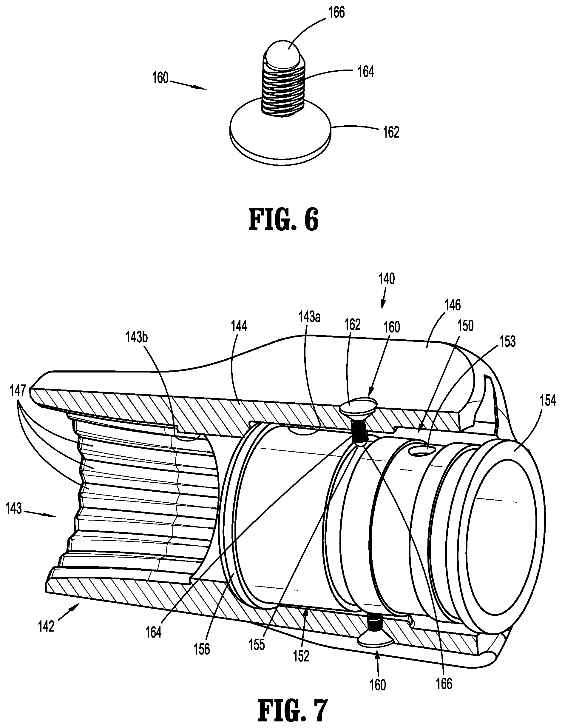
[0020] FIG. 6 is a side, perspective view of a screw of the rotation knob assembly shown in FIG. 4;
[0021] FIG. 7 is a side, cross-sectional view taken along line 7-7 shown in FIG. 4;
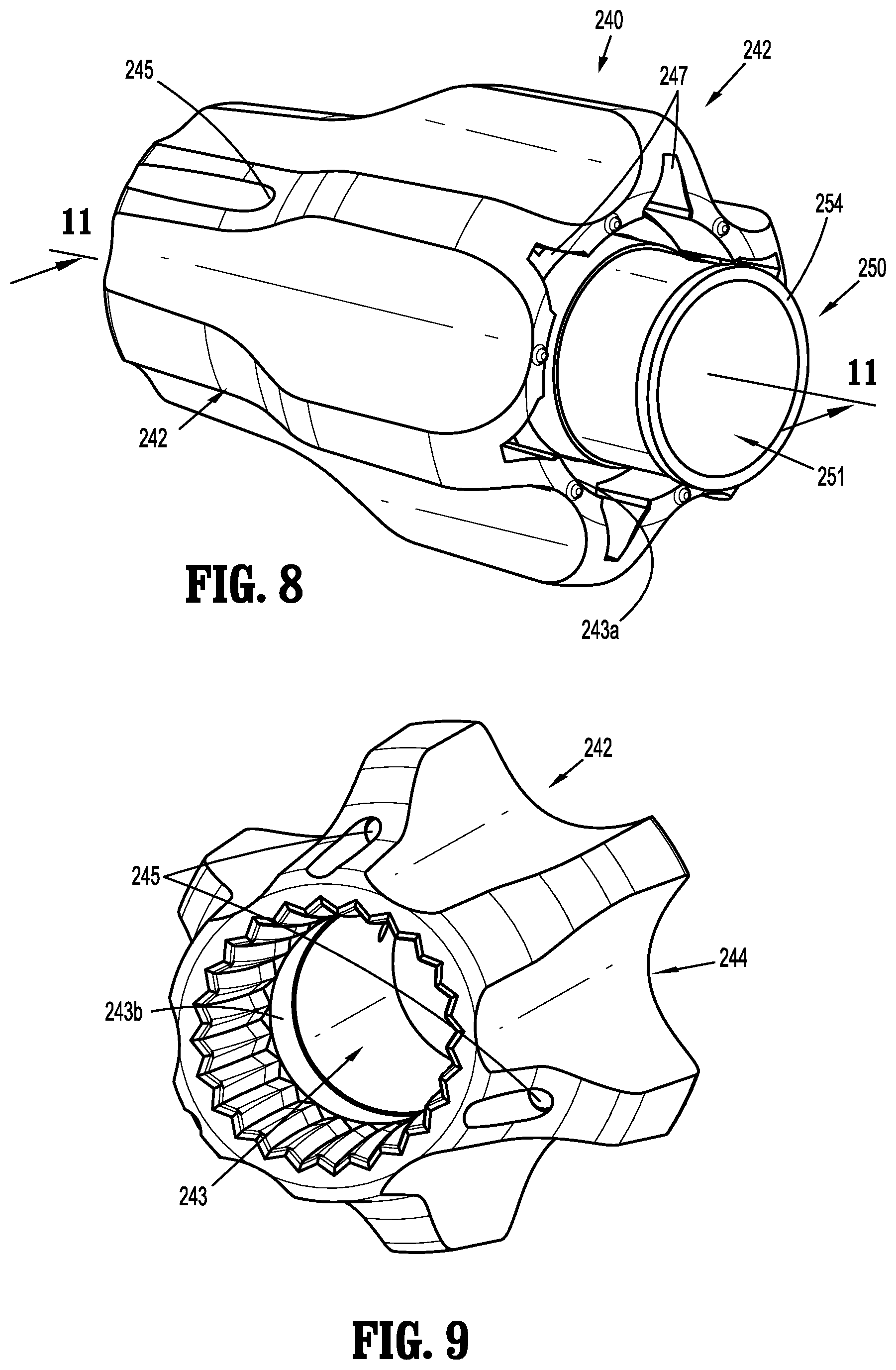
[0022] FIG. 8 is a side, perspective view of a rotation knob assembly according to another embodiment of the present disclosure;
[0023] FIG. 9 is an end, perspective view of an outer knob of the rotation knob assembly shown in FIG. 8;
[0024] FIG. 10 is a side, perspective view of the rotation knob assembly shown in FIG. 8 with parts separated;
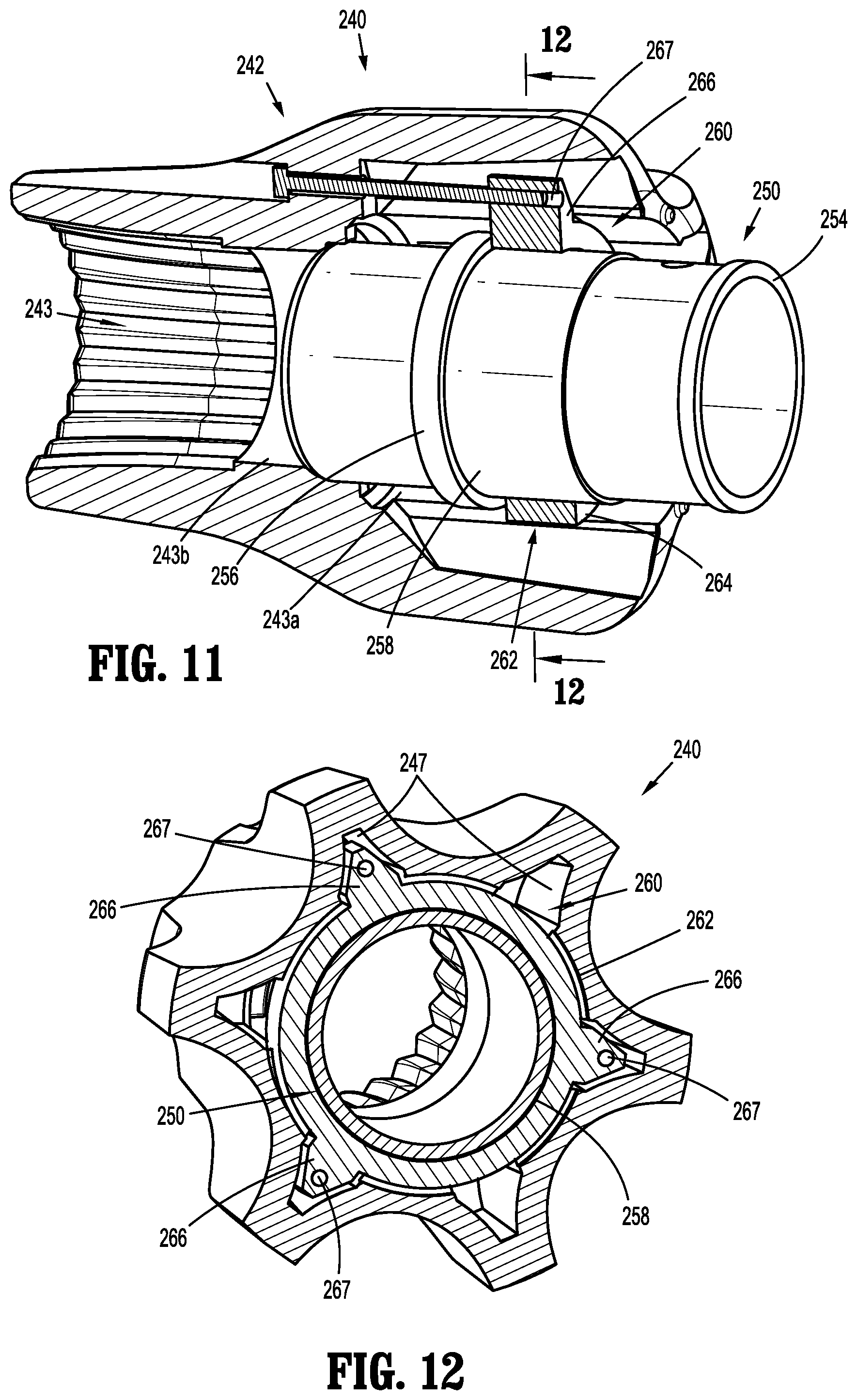
[0025] FIG. 11 is a side, cross-sectional view taken along line 11-11 shown in FIG. 8;
[0026] FIG. 12 is an end, cross-sectional view taken along line 12-12 shown in FIG. 11;
[0027] FIG. 13 is a side, perspective view of a rotation knob assembly according to another embodiment of the present disclosure;
[0028] FIG. 14 is a side, perspective view of the rotation knob assembly shown in FIG. 13 with parts separated;
[0029] FIG. 15 is a side, cross-sectional view taken along line 15-15 shown in FIG. 13;
[0030] FIG. 16 is an end, cross-sectional view taken along line 16-16 shown in FIG. 15;
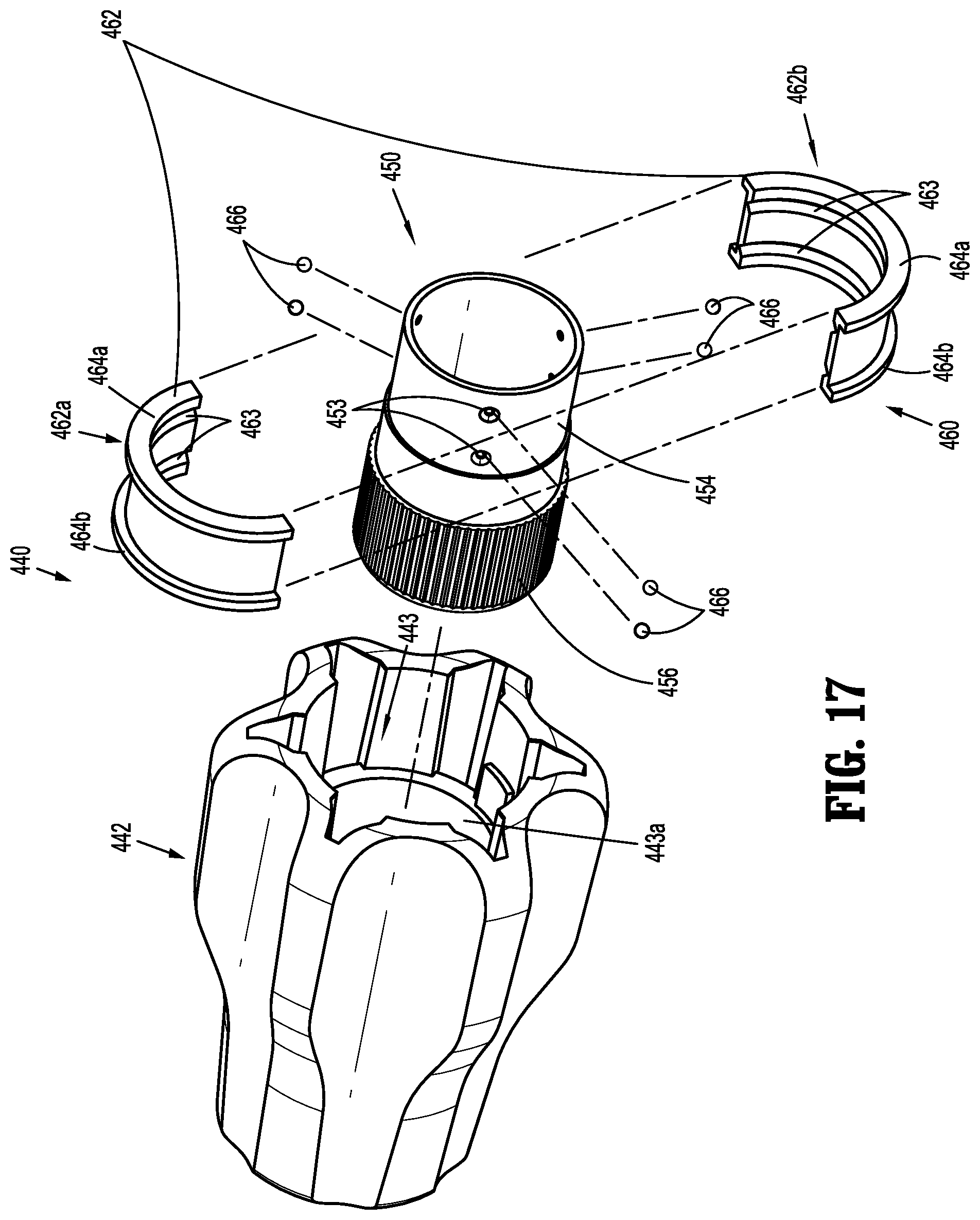
[0031] FIG. 17 is a side, perspective view of a rotation knob assembly according to another embodiment of the present disclosure with parts separated;
[0032] FIG. 18 is a side, cross-sectional view of the rotation knob assembly shown in FIG. 17; and
[0033] FIG. 19 is a cross-sectional end view taken along line 19-19 shown in FIG. 18.
DETAILED DESCRIPTION
[0034] As detailed herein and shown in the drawing figures, as is traditional when referring to relative positioning on a surgical instrument, the term "proximal" refers to the end of the apparatus or component thereof which is closer to the user and the term "distal" refers to the end of the apparatus or component thereof which is further away from the user. Further, to the extent consistent, any or all of the aspects and features detailed herein may be used in conjunction with any or all of the other aspects and features detailed herein.
[0035] The present disclosure provides rotation knob assemblies for surgical instruments. Although detailed herein as incorporated into a surgical clip applier, the rotation knob assemblies of the present disclosure may alternatively be incorporated into any suitable surgical instrument.
[0036] Turning to FIGS. 1 and 2, a surgical clip applier according to aspects of the present disclosure is shown generally as clip applier 10. The clip applier 10 generally includes a handle assembly 100 and an adapter assembly 20 selectively connectable to the handle assembly 100. The handle assembly 100 is configured to operate the adapter assembly 20 upon connection thereto, and may be configured as a sterilizable, reusable component such that handle assembly 100 may be repeatedly used with different and/or additional elongated assemblies (not shown) during the course of one or more surgical procedures. The adapter assembly 20 may be configured as single-use disposable component, limited-use disposable components, or reusable components, depending upon a particular purpose and/or the configuration of the particular elongated assembly. In either configuration, the need for multiple handle assemblies 100 is obviated and, instead, the surgeon need only select an appropriate elongated assembly, and connect that elongated assembly to the handle assembly 100 in preparation for use.
[0037] The handle assembly 100 includes a housing 110, an actuation mechanism 120 (FIG. 3) operably disposed within the housing 110, a latch assembly 130 (FIG. 3) operably disposed within housing 110, and a rotation knob assembly 140 operably coupled to a distal portion of housing 110. The housing 110 supports and/or encloses the operating components of handle assembly 100, the actuation mechanism 120 is configured to enable selective firing of one or more surgical clips (not shown) from the end effector (not shown) of the attached adapter assembly 20. The latch mechanism 130 is configured to facilitate releasable locking engagement of the adapter assembly 20 with handle assembly 100. The rotation knob assembly 140 enables the selective rotation of the attached adapter assembly 20 relative to the housing 110.
[0038] The handle assembly 100 will only be described to the extent necessary to fully disclose the aspects of the present disclosure. For a detailed description of the operation and function of an exemplary handle assembly, including an exemplary actuation mechanism and an exemplary latch assembly, please refer to commonly owned U.S. Prov. Pat. App. Ser. No. 62/581,144 ("the '144 application"), filed Nov. 3, 2017, the content of which is incorporated herein by reference in its entirety. Other exemplary embodiments of handle assemblies may be found in commonly owned Intl. Pat. App. Nos. PCT/CN2016/096666 and PCT/CN2016/071178, filed on Aug. 26, 2016 and Jan. 18, 2016, respectively, the content of each is hereby incorporated herein by reference in its entirety.
[0039] Referring to FIGS. 1 and 2, the adapter assembly 20 of the clip applier 10 generally includes a proximal hub 22, an elongated shaft 24 extending distally from the proximal hub 22, an end effector assembly (not shown) disposed towards a distal end portion of the elongated shaft 24, and an inner drive assembly (not shown) operably coupled between the handle assembly 100 and the end effector assembly when adapter assembly 20 is engaged with the handle assembly 100, to enable the sequential firing of at least one surgical clip (not shown) about tissue. The end effector may be integrally formed with the adapter assembly 20, or may be a separate component releasably secured to the adapter assembly 20. The end effector assembly may be configured to fire surgical clips similar to those shown and described in U.S. Pat. No. 7,819,886 or 7,905,890, the content of each of which is hereby incorporated herein by reference in its entirety.
[0040] With additional reference to FIG. 3, the housing 110 of the handle assembly 100 may be formed from first and second housing halves 110a, 110b that cooperate to define a body portion 112 and a fixed handle portion 114 depending from the body portion 112. The body portion 112 of the housing 110 includes a distal nose 116 defining a distal opening 117 (FIG. 3) therethrough. A proximal end portion of the proximal hub 22 of the adapter assembly 20 is configured to extend at least partially through the distal opening 117 of the distal nose 116 of the housing 110 when the adapter assembly 20 is engaged with the handle assembly 100.
[0041] The distal nose 116 of the body portion 112 of the housing 110 further includes an annular recess 119 defined on an interior surface thereof surrounding the distal opening 117. The annular recess 119 is configured to receive an annular protrusion 154 of an inner collar 150 of the rotation knob assembly 140 to secure the rotation knob assembly 140 with the distal nose 116 of the body portion 112 of the housing 110. To this end, the annular recess 119 and/or the annular protrusion 154 of the inner collar 150 may include one or more keying features to facilitate rotationally lock the inner collar 150 to the distal nose 116 of the housing 110. In embodiments, and as shown, the inner collar 150 defines an opening 153 (FIG. 5) that receives a tab (not shown) extending from the distal nose 116 of the body portion 112 of the housing 110 for longitudinally and rotationally locking the inner collar 150 relative to the housing 110.
[0042] With reference to FIGS. 3-7, an outer knob 142 of the rotation knob assembly 140 is rotatably coupled to the distal nose 116 of the body portion 112 of the housing 110 and is configured to receive the proximal hub 22 (FIG. 1) of the adapter assembly 20. As described below, the outer knob 142 of the rotation knob assembly 140 is coupled to the adapter assembly 20 in fixed rotational engagement therewith to enable selective rotation of the adapter assembly 20 relative to the housing 110 upon rotation of an outer knob 142 relative to housing 110. The rotation knob assembly 140 includes the outer knob 142, the inner collar 150, and a pair of screws 160 rotatably securing the outer knob 142 to the inner collar 150.
[0043] The outer knob 142 of the rotation knob assembly 140 may be formed from a polymeric material, e.g., a biocompatible, sterilizable plastic, or other suitable material, and includes a body 144 defining a substantially cone shaped-configuration tapering in diameter from a proximal end portion to a distal end portion thereof, although other suitable configurations are also contemplated. The body 144 defines a plurality of flutes 146 arranged radially about the body 144 to facilitate grasping or gripping of the body 144 by a user at any rotational orientation to enable rotation of the rotation knob assembly 140.
[0044] The body 144 of the outer knob 142 of the rotation knob assembly 140 defines a longitudinally-extending lumen 143 therethrough. The longitudinally-extending lumen 143 includes a proximal portion 143a and a distal portion 143b which may define equal or different diameters, e.g., the proximal portion 143a may define a larger diameter as compared to the distal portion 143b. The proximal portion 143a of lumen 143 communicates with the proximal opening of the body 144 of the outer knob 142. The body 144 of the outer knob 142 defines a pair of threaded transverse apertures 145 (FIG. 5, only one shown) that communicate with the proximal portion 143a of the lumen 143. Each of the threaded transverse apertures 145 is configured to receive one of the screws 160 as detailed below.
[0045] The distal portion 143b of the lumen 143 communicates with the distal opening of the body 144 of the outer knob 142 at the distal end thereof and with the proximal portion 143a of the lumen 143 at the proximal end thereof. The body 144 includes a plurality of longitudinally-extending grooves 147 arranged annularly on an interior surface thereof and disposed about at least a portion of the distal portion 143b of the lumen 143. The grooves 147 are configured to slidably receive indexing protrusions 22a (FIG. 2) of the proximal hub 22 of adapter assembly 20 to rotationally fix the proximal hub 22 relative to the outer knob 142 upon insertion of proximal hub 22 into handle assembly 100.
[0046] The inner collar 150 of the rotation knob assembly 140 may be formed from a metal, e.g., stainless steel, or other suitable material, and includes a body 152 defining a longitudinally-extending lumen 151 therethrough. The inner collar 150 further includes an annular protrusion 154 disposed about a proximal end portion thereof and a distal head 156 disposed about a distal end portion thereof. The inner collar 150 defines an annular groove or channel 155 defined within an exterior surface of the inner collar 150, disposed between the annular protrusion 154 and the distal head 156. The annular protrusion 154, as noted above, is configured for receipt within the annular recess 119 of the distal nose 116 of the housing 110 (see FIG. 3) to engage the inner collar 150 with the distal nose 116 of the body portion 112 of the housing 110, e.g., upon engagement of the first and second housing halves 110a, 110b (FIG. 1) forming the housing 110 with one another. As noted above, the inner collar 150 defines the opening 154 for receiving a tab (not shown) extending from the distal nose 116 of the housing 110 for rotationally locking the inner collar 150 relative to the housing 110.
[0047] The inner collar 150 is configured to be received within the proximal portion 143a of the lumen 143 of the body 144 of the outer knob 142. The inner collar 150 is configured such that the annular groove 155 aligns with the pair of threaded transverse apertures 145 in the body 144 of the outer knob 142 when the outer knob 142 is received about the inner collar 150.
[0048] With particular reference to FIG. 6, each screw 160 of the rotation knob assembly 140 includes a head portion 162, a threaded post portion 164 extending from the head 162, and a ball portion 166 disposed on an end of the threaded post portion 164. In embodiments, at least the ball portion 166 of the screws 160 is formed from PLASTITE.RTM. (a registered trademark of Research Engineering & Manufacturing, Inc., Rhode Island) or other low friction or lubricious material to facilitate rotation of the outer knob 142 of the rotation knob assembly 140 relative to the inner collar 150. In alternative embodiments, the screws are biased radially inward to facilitate assembly of the rotation knob assembly.
[0049] Turing to FIG. 7, the screws 160 of the rotation knob assembly 140 are received within the transverse apertures 145 defined through the body 144 of the outer knob 142, and are oriented such that the ball portions 166 of the screws 160 protrude radially inwardly into the proximal portion 143a of the lumen 143 of the body 144 of the outer knob 142. As noted above, the annular groove 155 of the inner collar 150 aligns with the transverse apertures 145 in the outer knob 142 when the outer knob 142 is received about the inner collar 150. In this manner, the ball portions 166 of the screws 166 extending from the transvers apertures 145 are received within the annular groove 155 of the inner collar 150 to rotatably retain the outer knob 142 relative to the inner collar 150. The ball portions 166 of the screws 160 are configured to provide minimal friction with inner collar 150 to allow ease of rotation of the outer knob 142 relative to the inner collar 150. The outer knob 142 may be rotated continuously through an infinite number of positions.
[0050] With reference now to FIGS. 8-12, a rotation knob assembly according to another embodiment of the present disclosure is shown generally as rotation knob assembly 240. The rotation knob assembly 240 is substantially similar to rotation knob assembly 140 described herein above, and will only be described in detail as relates to the differences therebetween.
[0051] The rotation knob assembly 240 includes an outer knob 242, an inner collar 250, and a bearing assembly 260 rotatable securing the outer knob 242 to the inner collar 250. The outer knob 242 includes a body 244 defining a longitudinally-extending lumen 243 therethrough. The longitudinally-extending lumen 243 includes a proximal portion 243a and a distal portion 243b. The body 244 of the outer knob 242 defines a plurality of longitudinally extending openings 245 that communicate with the proximal portion 243a of the lumen 243. Each of the longitudinal openings 245 is configured to receive a locking member 270 (FIG. 10) as detailed below. The body 244 of the outer knob 242 also defines a plurality of notches 247 extending radially outward from the proximal portion 243a of the longitudinally extending lumen 243. The notches 247 accommodate protrusions 266 of an annular body 264 of the bearing member 262 of the bearing assembly 260.
[0052] The inner collar 250 of the rotation knob assembly 240 includes a body 252. The inner collar 250 includes an annular protrusion 254 disposed about a proximal end portion thereof, an annular flange 256 disposed about a mid-portion thereof, and a bearing surface 258 disposed between the annular protrusion 254 and the annular flange 256. As described below, the bearing surface 258 of the inner collar 250 is configured to rotatably support the bearing member 262 of the bearing assembly 260.
[0053] The bearing assembly 260 of the rotation knob assembly 240 includes the bearing member 262 and the plurality of fastening members 270. The bearing member 262 includes an annular body 264 and a plurality of protrusions 266 extending radially outward from the annular body 264. The annular body 264 of the bearing member 266 is configured to be received about the bearing surface 258 of the inner collar 250 and within the proximal portion 243a of the lumen 243 in the outer knob 242 of the rotation knob assembly 240. The protrusions 266 of the bearing member 262 are configured to be received within the notches 247 in the body 244 of the outer knob 242. Although shown as having three protrusions 266 with a triangular shape, it is envisioned that the bearing member 262 may include any number of protrusions 266 and the protrusions 266 may include any suitable shape. The number and shape of the notches 247 in the body 244 of the outer knob 242 correspond to the number and shape of the protrusions 266. Each of the protrusions 266 of the bearing member 262 defines an opening 267 for engaging a proximal end of one of the fastener members 270.
[0054] The fastener members 270 of the rotation knob assembly 240 may include a threaded outer surface (not shown) for threading engagement with the protrusions 266 of the bearing member 262. Alternatively, the fastener members 270 may be received within the openings 267 in the protrusions 266 of the bearing member 262 with a friction fit. The fastener members 270 may be further secured to the protrusions 266 of the bearing member 262 with adhesive. In embodiments, either or both of inner collar 250 and the bearing member 262 are formed from PLASTITE.RTM. or other low friction or lubricious material to facilitate rotation of the bearing member 262 relative to the inner collar 250. Alternatively, either or both of the bearing member 262 and inner collar 250 may include a friction reducing coating to facilitate rotation of the outer knob 242 about the inner collar 250.
[0055] With reference now to FIG. 13-16, another embodiment of a rotation knob assembly according to the present disclosure is shown generally as rotation knob assembly 340. The rotation knob assembly 340 is substantially similar to rotation knob assemblies 140, 240 described herein above, and will only be described in detail as relates to the differences therebetween.
[0056] The rotation knob assembly 340 includes an outer knob 342, an inner collar 350, and a snap ring 360. The outer knob 342 includes a body 344 defining a longitudinally-extending lumen 343 therethrough. The longitudinally-extending lumen 343 includes a proximal portion 343a and a distal portion 343b. The body 344 of the outer knob 342 defines an annular groove 345 disposed within the proximal portion 343a of the longitudinally extending lumen 343. The annular groove 345 is configured to receive a plurality of flange portions 364 of the snap ring 360. Alternatively, the body 344 of the outer knob 342 includes a plurality of cutouts (not shown) for accommodating the plurality of flange portions 364 of the snap ring.
[0057] The inner collar 350 of the rotation knob assembly 340 includes a body 352. The inner collar 350 includes an annular protrusion 354 disposed about a proximal end portion thereof and distal head sections 356 disposed about a mid-portion thereof. The inner collar 350 defines an annular groove 355 disposed between the annular protrusion 354 and the annular flange sections 356. As described below, the annular groove 355 is configured to accept the snap ring 360 of the rotation knob assembly 340.
[0058] The snap ring 360 of the rotation knob assembly 340 includes alternating annular segments 362 and flange segments 364. Together the annular segments 362 define a cylindrical opening 363 configured to be received within the annular groove 355 in the inner collar 350. The flange segments 364 of the snap ring 360 extend outwardly between the annular segments 362 and are configured to be received within the annular groove 345 in the proximal portion 343a of the longitudinally extending lumen 343 of the body 352 of the outer knob 350.
[0059] The snap ring 360 may be secured within the annular groove 345 of the outer knob 342 in a rotationally fixed condition such that the snap ring 360 rotates along with the outer knob 342 when the outer knob 342 is rotated relative to the inner collar 350. In this manner, the snap ring 360 is rotatably received within the annular groove 355 of the inner collar 350 and the snap ring 360 and outer knob 342 rotate relative to the inner collar 350. Alternatively, the snap ring 360 may be secured within the annular groove 345 of the inner collar 350 in a rotationally fixed condition such that the snap ring 360 does not rotate with the outer knob 342 as the outer knob 342 is rotated relative to the inner collar 350. In this manner, the snap ring 360 is rotatably received within the annular groove 345 of the outer knob 342 and the outer knob 342 rotates relative to the snap ring 360. In embodiments the snap ring 360 may be rotationally received within the annular groove 345 of the outer knob 342 and the annular groove 355 of the inner collar 350 such that the snap ring 360 may rotate relative to either or both of the outer knob 342 and inner collar 350 when the outer knob 342 is rotated relative to the inner collar 350.
[0060] With reference now to FIG. 17-19, still another embodiment of a rotation knob assembly according to the present disclosure is shown generally as rotation knob assembly 440. The rotation knob assembly 440 is substantially similar to rotation knob assemblies 140, 240, 340 described herein above, and will only be described in detail as relates to the differences therebetween.
[0061] The rotation knob assembly 440 includes an outer knob 442, an inner collar 450, and a bearing assembly 460. The outer knob 442 includes a body 444 defining a longitudinally-extending lumen 443 therethrough. The longitudinally-extending lumen 443 includes a proximal portion 443a and a distal portion 443b. The body 444 includes a plurality of longitudinally-extending grooves 447 arranged annularly on an interior surface thereof and disposed about at least a portion of the proximal portion 443a of the lumen 443. The grooves 447 frictionally engage a grooved outer surface 456 of the inner collar 450.
[0062] The inner collar 450 of the rotation knob assembly 440 includes a body 452. The inner collar 450 includes a bearing surface 454 disposed about a proximal end portion thereof and the grooved outer surface 456 about a distal portion thereof. A plurality of paired semi-spherical recesses 453 are defined in the bearing surface 454 of the inner collar 450. As described below, the semi-spherical recesses 453 support ball bearings 466 of the bearing assembly 460. The grooved outer surface 456 of the inner collar 450 frictionally engages and rotationally fixes the inner collar 450 to the outer knob 442.
[0063] The bearing assembly 460 of the rotation knob assembly 440 includes an annular housing 462 having first and second housing halves 462a, 462b. The annular housing 462 includes proximal and distal annular flanges 464a, 464b. The proximal annular flange 464a of the annular housing 462 is configured to be received within the annular recess 119 (FIG. 3) in the distal nose 116 (FIG. 3) of the body portion 114 (FIG. 3) of the housing 110. The distal annular flange 464b of the annular housing 462 is configured to be received within the proximal portion 443a of the lumen 443 of the body 444 of the outer knob 442 to support the inner collar 450 within the outer knob 442.
[0064] The annular housing 462 of the bearing assembly 460 defines a pair of annular grooves 463 that align with the plurality of paired semi-spherical recesses 453 in the inner collar 450 when the inner collar 450 is received within the outer knob 442. The annular grooves 463 cooperate with the semi-spherical recesses 453 to support the ball bearings 466. Receipt of the ball bearings 466 within the semi-spherical recesses 453 and the annular grooves 463 longitudinally fixes the outer knob 442 and the inner collar 450 relative to the housing 112 of the handle assembly 100 and facilitates rotation of the outer knob 442 relative to the housing 110.
[0065] It should be understood that the foregoing description is only illustrative of the present disclosure. Various alternatives and modifications can be devised by those skilled in the art without departing from the disclosure. Accordingly, the present disclosure is intended to embrace all such alternatives, modifications and variances. The embodiments described with reference to the attached drawing figures are presented only to demonstrate certain examples of the disclosure. Other elements, steps, methods and techniques that are insubstantially different from those described above and/or in the appended claims are also intended to be within the scope of the disclosure.
* * * * *
D00000
D00001
D00002
D00003
D00004
D00005
D00006
D00007
D00008
D00009
D00010
D00011
D00012

XML
uspto.report is an independent third-party trademark research tool that is not affiliated, endorsed, or sponsored by the United States Patent and Trademark Office (USPTO) or any other governmental organization. The information provided by uspto.report is based on publicly available data at the time of writing and is intended for informational purposes only.
While we strive to provide accurate and up-to-date information, we do not guarantee the accuracy, completeness, reliability, or suitability of the information displayed on this site. The use of this site is at your own risk. Any reliance you place on such information is therefore strictly at your own risk.
All official trademark data, including owner information, should be verified by visiting the official USPTO website at www.uspto.gov. This site is not intended to replace professional legal advice and should not be used as a substitute for consulting with a legal professional who is knowledgeable about trademark law.