Configurable Strap
Warner; H Ty ; et al.
U.S. patent application number 16/506490 was filed with the patent office on 2020-01-16 for configurable strap. The applicant listed for this patent is Ty Inc.. Invention is credited to Alexia Bums, H Ty Warner.
| Application Number | 20200015561 16/506490 |
| Document ID | / |
| Family ID | 69140329 |
| Filed Date | 2020-01-16 |


| United States Patent Application | 20200015561 |
| Kind Code | A1 |
| Warner; H Ty ; et al. | January 16, 2020 |
CONFIGURABLE STRAP
Abstract
A configurable strap in connection with a bag or similar device is provided. In some embodiments, the bag includes a first mount point and a second mount point and the configurable strap is configured to couple to the first mount point and the second mount point in different configurations to form an across the body strap, a shoulder length strap, a small handle strap, or a clutch length strap.
| Inventors: | Warner; H Ty; (Westmont, IL) ; Bums; Alexia; (Westmont, IL) | ||||||||||
| Applicant: |
|
||||||||||
|---|---|---|---|---|---|---|---|---|---|---|---|
| Family ID: | 69140329 | ||||||||||
| Appl. No.: | 16/506490 | ||||||||||
| Filed: | July 9, 2019 |
Related U.S. Patent Documents
| Application Number | Filing Date | Patent Number | ||
|---|---|---|---|---|
| 62696238 | Jul 10, 2018 | |||
| Current U.S. Class: | 1/1 |
| Current CPC Class: | A45C 13/30 20130101; A45C 3/02 20130101; A45F 3/14 20130101; A45F 2003/142 20130101 |
| International Class: | A45C 13/30 20060101 A45C013/30 |
Claims
1. A configurable strap comprising: a first strap portion having an adjustable section, a first clasp on a first end of the first strap portion, and a second clasp on a second end of the first strap portion opposite the first end of the first strap portion; and a second strap portion a third clasp on a first end of the second strap portion, and a fourth clasp on a second end of the second strap portion opposite the first end of the second strap portion, wherein the first clasp and the third clasp are configured to couple together to join together the first strap portion and the second strap portion, wherein the first clasp, the second clasp, the third clasp, and the fourth clasp are configured to connect to a bag mount point wherein manipulation of the adjustable section is configured to increase or decrease a first length of the first strap portion, and wherein the second strap portion has a second length that is less than the shortest possible value for the first length of the first strap portion.
2. The configurable strap of claim 1 wherein the first clasp, the second clasp, the third clasp, and the fourth clasp include loop connectors, hooks, lobster claws, spring rings, fold over clasps, magnets, or buttons.
3. A system comprising: a configurable strap; and a bag having a first mount point and a second mount point, wherein the configurable strap is configured to couple to the first mount point and the second mount point in different configurations to form an across the body strap, a shoulder length strap, a small handle strap, or a clutch length strap.
4. The system of claim 3 wherein the configurable strap includes a first strap portion, a first clasp on a first end of the first strap portion, a second clasp on a second end of the first strap portion opposite the first end of the first strap portion, a second strap portion shorter than the first strap portion, a third clasp on a first end of the second strap portion, and a fourth clasp on a second end of the second strap portion opposite the first end of the second strap portion.
5. The system of claim 4 wherein, when the first clasp and the third clasp are coupled together to join together the first strap portion and the second strap portion, the second clasp is coupled to the first mount point, and the fourth clasp is coupled to the second mount point, the configurable strap forms the across the body strap.
6. The system of claim 4 wherein, when the first clasp and the third clasp are disconnected to separate the first strap portion and the second strap portion, the first clasp is coupled to the first mount point, and the second clasp is coupled to the second mount point, the configurable strap forms the shoulder length strap.
7. The system of claim 4 wherein, when the first clasp and the third clasp are disconnected to separate the first strap portion and the second strap portion, the third clasp is coupled to the first mount point, and the fourth clasp is coupled to the second mount point, the configurable strap forms the small handle strap.
8. The system of claim 4 wherein, when the first clasp and the third clasp are disconnected to separate the first strap portion and the second strap portion, the third clasp and the second clasp are both coupled to either the first mount point or the second mount point, the configurable strap forms the clutch length strap.
9. The system of claim 4 wherein the first clasp, the second clasp, the third clasp, and the fourth clasp include loop connectors, hooks, lobster claws, spring rings, fold over clasps, magnets, or buttons.
10. The system of claim 4 wherein the bag resembles a plush toy or character.
11. A method comprising: coupling together a first strap portion and a second strap portion; coupling a first end of the joined together first strap portion and the second strap portion to a first mount point of a bag and a second end of the joined together first strap portion and the second strap portion to a second mount point of the bag to form an across the body strap.
12. The method of claim 11 further comprising: decoupling the first end of the joined together first strap portion and the second strap portion from the first mount point and the second end of the joined together first strap portion and the second strap portion from the second mount point; decoupling the first strap portion and the second strap portion; and coupling a first end of the first strap portion to the first mount point and a second end of the first strap portion to the second mount point to form a shoulder length strap.
13. The method of claim 11 further comprising: decoupling the first end of the joined together first strap portion and the second strap portion from the first mount point and the second end of the joined together first strap portion and the second strap portion from the second mount point; decoupling the first strap portion and the second strap portion; and coupling a first end of the first strap portion to the first mount point and a second end of the first strap portion to the second mount point to form a shoulder length strap.
14. The method of claim 11 further comprising: decoupling the first end of the joined together first strap portion and the second strap portion from the first mount point and the second end of the joined together first strap portion and the second strap portion from the second mount point; decoupling the first strap portion and the second strap portion; and coupling both a first end and a second end of the second strap portion either to the first mount point or the second mount point to form a clutch length strap.
Description
CROSS REFERENCE TO RELATED APPLICATIONS
[0001] This application claims priority to U.S. Provisional Patent Application No. 62/696,238 filed Jul. 10, 2018 and titled "CONFIGURABLE STRAP." U.S. Provisional Patent Application No. 62/696,238 is hereby fully incorporated by reference as if set forth fully herein.
FIELD
[0002] The present invention relates generally to a configurable strap in connection with a bag or similar device.
BACKGROUND
[0003] Current bag strap designs have limited size options or require multiple separate distinct straps to accommodate customer demand for different carrying lengths. These limitations require customers to either keep track of multiple straps or settle for carrying the attached bag or similar device at an inconvenient length.
[0004] In view of the above, there is a continuing, ongoing need for improved systems and methods.
BRIEF DESCRIPTION OF THE DRAWINGS
[0005] FIG. 1 illustrates a configurable strap according to an exemplary embodiment;
[0006] FIG. 2 illustrates a portion of a configurable strap according to an exemplary embodiment;
[0007] FIG. 3 illustrates a portion of a configurable strap according to an exemplary embodiment;
[0008] FIG. 4 illustrates a bag for use in conjunction with a configurable strap according to an exemplary embodiment;
[0009] FIG. 5 illustrates a bag and a portion of a configurable strap according to an exemplary embodiment;
[0010] FIG. 6 illustrates a bag and a portion of a configurable strap according to an exemplary embodiment;
[0011] FIG. 7 illustrates a bag and a portion of a configurable strap according to an exemplary embodiment;
[0012] FIG. 8 illustrates a bag and a configurable strap according to an exemplary embodiment; and
[0013] FIG. 9 illustrates a bag and a portion of a configurable strap according to an exemplary embodiment.
DETAILED DESCRIPTION
[0014] While this invention is susceptible of embodiment in many different forms, there are shown in the drawings and will be described herein in detail specific embodiments thereof with the understanding that the present disclosure is to be considered as an exemplification of the principles of the invention. It is not intended to limit the invention to the specific illustrated embodiments.
[0015] Embodiments disclosed herein include a convertible strap. The convertible strap can include two distinct portions that can be selectively coupled together or selectively coupled to a bag or similar device to change the length of the strap and adjust the carrying style of the bag.
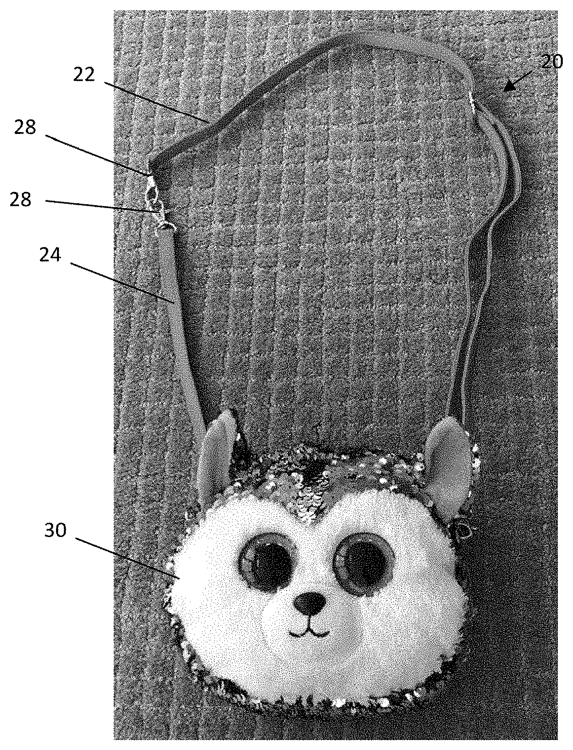
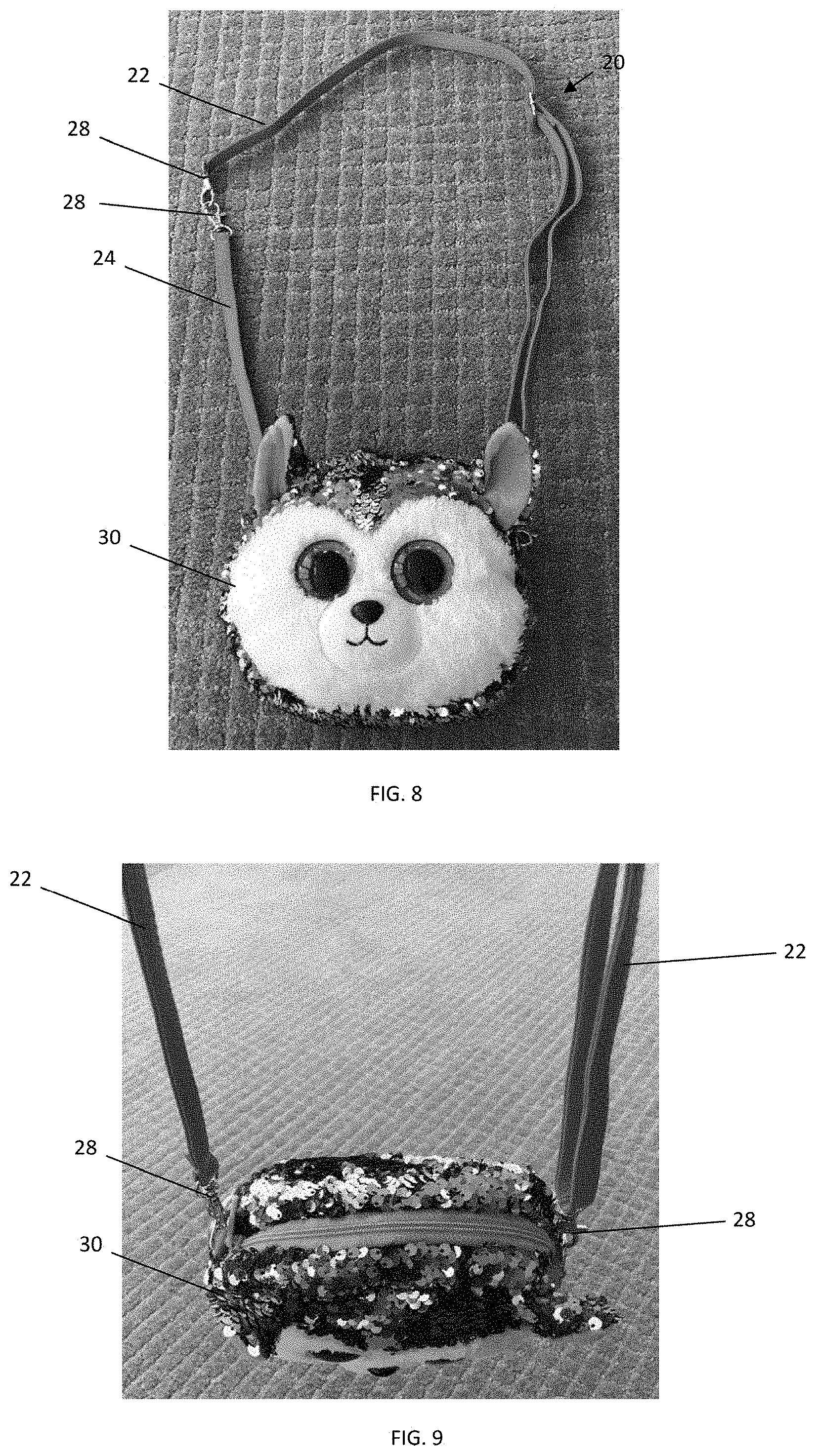
[0016] FIG. 1 is view of a convertible strap 20 in accordance with disclosed embodiments. As seen in FIG. 1 the convertible strap 20 can include a first strap portion 22 removably coupled to a second strap portion 24. FIG. 2 is a view of the first strap portion 22. As seen in FIG. 2, the first strap portion 22 can include an adjustable section 26 and clasps 28 on opposing ends of the first strap portion 22. The adjustable section 26 can be manipulated to lengthen or shorten the first strap portion 22 as known by those having ordinary skill in the art. FIG. 3 is a view of the second strap portion 24. As seen in FIG. 3, the second strap portion includes a single section that is shorter than the overall length of the first strap portion 22 and claps 28 on opposing ends of the second strap portion 24. In some embodiments, the second strap portion 24 can include an adjustable section similar to the adjustable section 26 of the first strap portion 22. Various embodiments for the claps 28 are contemplated, including but not limited to, loop connectors, hooks, lobster claws, spring rings, fold over clasps, magnets, buttons, and other known clasp types in the art.
[0017] FIG. 4 is a front view of a bag 30 for use in connection with the convertible strap 20 in accordance with disclosed embodiments. As seen in FIG. 4, in some embodiments the bag 30 can resemble a plush toy or similar designed character. However, it should be noted that the convertible strap 20 can be used in connection with additional bag designs known in the art.
[0018] FIG. 5 and FIG. 6 are views of the bag 30 being used in conjunction with the convertible strap 20. As seen in FIG. 5 and FIG. 6 the second strap portion 24 can be decoupled from the first strap portion 22 and the clasps 28 of the second strap portion 28 can be jointly coupled to a single mount point on the bag 30. In such embodiments as shown in FIG. 5 and FIG. 6, the second strap portion 24 can form a wristlet so that the bag 30 can be used as a clutch. As seen in FIG. 7, in some embodiments, the clasps 28 of the second strap portion 24 can be coupled to different mount points on opposite sides of the bag 30 to create a small handle strap.
[0019] FIG. 8 is a view of the bag 30 being used in conjunction with the entire convertible strap 20. As seen in FIG. 8, a first one of the clasps 28 of the first strap portion 22 can be coupled to a first mount point on the bag 30, a second one of the clasps 28 of the first strap portion 22 can be coupled to a first one of the clasps 28 of the second strap portion 24, and a second one of the clasps 28 of the second strap portion 24 can be coupled to a second mount point on the bag 30. In some embodiments, the second mount point on the bag 30 can be on an opposite side of the bag 30 from the first mount point. In such embodiments as shown in FIG. 8, the second strap portion 24 can form an across the body length strap so that the bag 30 can be worn across a user's body.
[0020] FIG. 9 is a view of the bag 30 being used in conjunction with the convertible strap 20. As seen in FIG. 8, the second strap portion 24 can be decoupled entirely from the first strap portion 22 to form a smaller total length strap, a first one of the clasps 28 of the first strap portion 22 can be coupled to a first mount point on the bag 30, and a second one of the clasps 28 of the first strap portion 22 can be coupled to a second mount point on the bag 28. In some embodiments, the second mount point on the bag 30 can be on an opposite side of the bag 30 from the first mount point. In such embodiments as shown in FIG. 9, the second strap portion 24 can form a shoulder length strap so that the bag 30 can be worn on a single shoulder of a user's body.
[0021] The present disclosure can also be directed to methods for altering the convertible strap 20 to from different lengths and handle styles for use with the bag 30. For example, the claps 28 can be coupled and decoupled from each other and various mount points on the bag 30 as described herein to from at least a wristlet length strap, a handle length strap, a shoulder length strap, and an across the body length strap.
[0022] From the foregoing, it will be observed that numerous variations and modifications may be effected without departing from the spirit and scope of the invention. It is to be understood that no limitation with respect to the specific system or method described herein is intended or should be inferred. It is, of course, intended to cover all such modifications as fall within the sprit and scope of the invention.
* * * * *
D00000
D00001
D00002
D00003
D00004
XML
uspto.report is an independent third-party trademark research tool that is not affiliated, endorsed, or sponsored by the United States Patent and Trademark Office (USPTO) or any other governmental organization. The information provided by uspto.report is based on publicly available data at the time of writing and is intended for informational purposes only.
While we strive to provide accurate and up-to-date information, we do not guarantee the accuracy, completeness, reliability, or suitability of the information displayed on this site. The use of this site is at your own risk. Any reliance you place on such information is therefore strictly at your own risk.
All official trademark data, including owner information, should be verified by visiting the official USPTO website at www.uspto.gov. This site is not intended to replace professional legal advice and should not be used as a substitute for consulting with a legal professional who is knowledgeable about trademark law.