Waterproof Shoe Structure
Hsu; Walter W.
U.S. patent application number 16/032163 was filed with the patent office on 2020-01-16 for waterproof shoe structure. The applicant listed for this patent is Welter's Co., Ltd.. Invention is credited to Walter W. Hsu.
| Application Number | 20200015542 16/032163 |
| Document ID | / |
| Family ID | 69140230 |
| Filed Date | 2020-01-16 |


| United States Patent Application | 20200015542 |
| Kind Code | A1 |
| Hsu; Walter W. | January 16, 2020 |
Waterproof Shoe Structure
Abstract
A waterproof shoe structure includes a sole, a vamp mounted on the sole, and a waterproof lining mounted on the vamp. The vamp is provided with a plurality of vent holes. The waterproof lining has a surface provided with a plurality of convex portions and a plurality of concave portions between the convex portions. Each of the convex portions is higher than each of the concave portions. Each of the convex portions is provided with a through hole connected to each of the vent holes of the vamp. The through hole of each of the convex portions and each of the vent holes of the vamp are integrated to connect an inner space of the vamp to an ambient environment.
| Inventors: | Hsu; Walter W.; (Dou Liu City, TW) | ||||||||||
| Applicant: |
|
||||||||||
|---|---|---|---|---|---|---|---|---|---|---|---|
| Family ID: | 69140230 | ||||||||||
| Appl. No.: | 16/032163 | ||||||||||
| Filed: | July 11, 2018 |
| Current U.S. Class: | 1/1 |
| Current CPC Class: | A43B 23/0235 20130101; A43B 23/022 20130101; A43B 23/07 20130101; A43B 7/12 20130101; A43B 7/125 20130101; A43B 7/085 20130101; A41B 2400/22 20130101 |
| International Class: | A43B 7/12 20060101 A43B007/12; A43B 23/02 20060101 A43B023/02; A43B 7/08 20060101 A43B007/08 |
Claims
1. A shoe structure comprising: a sole; a vamp mounted on the sole; and a waterproof lining mounted on the vamp; wherein: the vamp is provided with a plurality of vent holes; the waterproof lining has a surface provided with a plurality of convex portions and a plurality of concave portions between the convex portions; each of the convex portions is higher than each of the concave portions; each of the convex portions is provided with a through hole connected to each of the vent holes of the vamp; the through hole of each of the convex portions and each of the vent holes of the vamp are integrated to connect an inner space of the vamp to an ambient environment; when rainwater drops, the rainwater directly flows down from the convex portions to the concave portions of the waterproof lining, without staying on the convex portions; when the rainwater drops onto the through hole of each of the convex portions, the rainwater does not enter the through hole of each of the convex portions by a capillary action; when the vamp is compressed by an external force, air in the inner space of the vamp is forced to flow through each of the vent holes of the vamp and the through hole of each of the convex portions, and is drained outward from the through hole of each of the convex portions into the ambient environment; and when the vamp is released and restored to an original state after the external force disappears, the air from the ambient environment is introduced through the through hole of each of the convex portions and each of the vent holes of the vamp into the inner space of the vamp.
2. The shoe structure of claim 1, wherein each of the convex portions has a semispherical shape.
3. The shoe structure of claim 1, wherein the through hole of each of the convex portions is disposed at a vertical state.
4. The shoe structure of claim 1, wherein the through hole extends downward from a central position of a top face of each of the convex portions.
5. The shoe structure of claim 1, wherein the through hole of each of the convex portions has a small diameter.
6. The shoe structure of claim 1, wherein each of the vent holes extends through a whole thickness of the vamp, and the through hole extends through a whole thickness of each of the convex portions.
7. The shoe structure of claim 1, wherein the waterproof lining is mounted on a helmet.
8. The shoe structure of claim 1, wherein the waterproof lining is mounted on a raincoat.
Description
BACKGROUND OF THE INVENTION
1. Field of the Invention
[0001] The present invention relates to a shoe structure and, more particularly, to a waterproof shoe structure.
2. Description of the Related Art
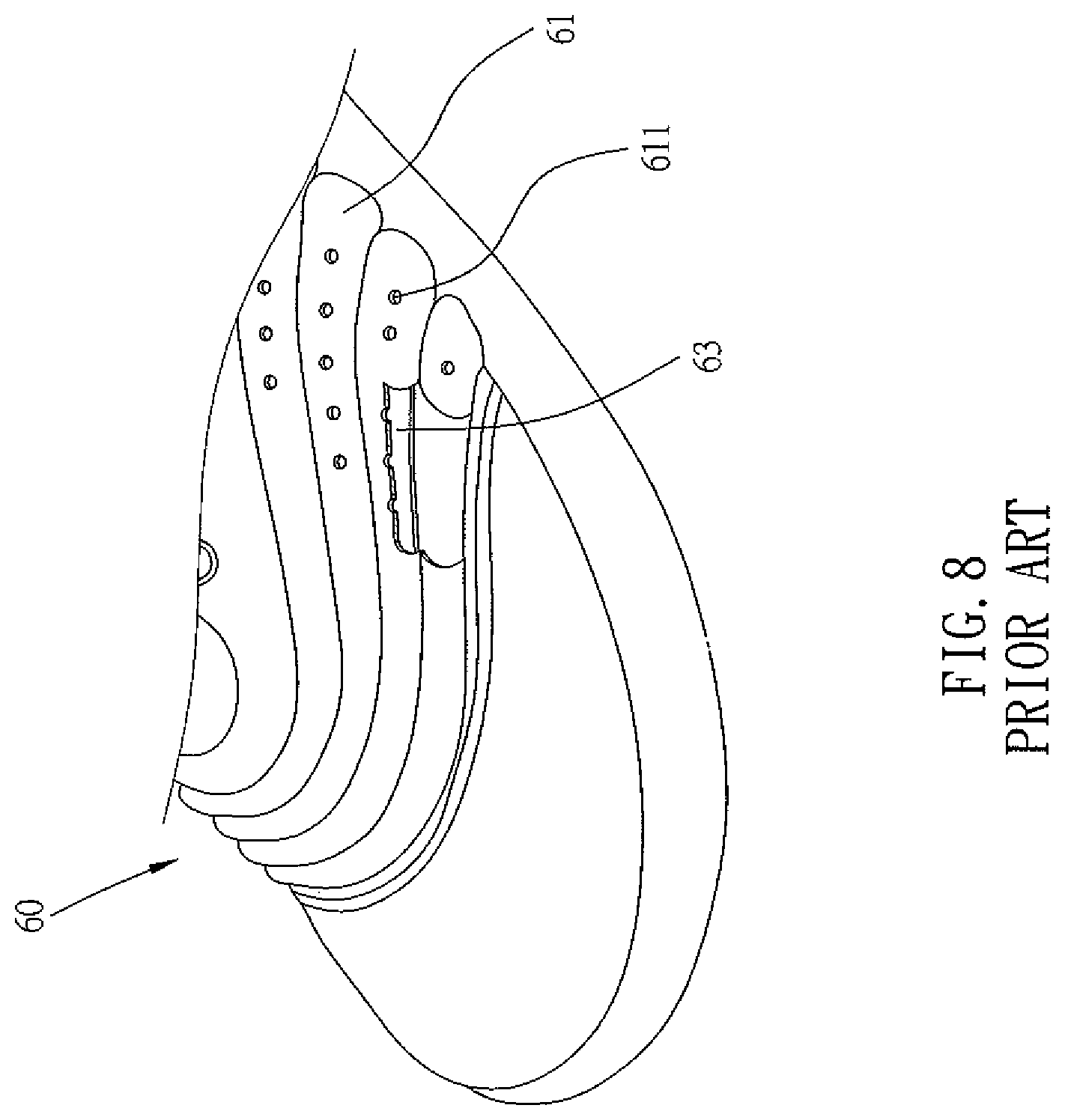
[0002] A conventional waterproof shoe structure 60 in accordance with the prior art shown in FIGS. 8 and 9 comprises a sole, a vamp mounted on the sole, a covering layer 61 mounted on the sole, and an inner bottom layer 62 mounted on the sole. The covering layer 61 has multiple through holes 611. The inner bottom layer 62 has multiple vent holes 621. A plurality of air channels 63 are formed between the covering layer 61 and the inner bottom layer 62. The hot wet air in the shoe structure is introduced through the vent holes 621, the air channels 63 and the through holes 611 and are drained outward into the ambient environment, thereby providing an aerating function. However, the through holes 611 and the covering layer 61 are located at the same horizontal plane, so that the rainwater easily infiltrates through the through holes 611 into the inner space of the vamp. Thus, it is necessary to provide the inner bottom layer 62 for forming the air channels 63 to guide the rainwater, and to drain the rainwater outward from the through holes 611 of the covering layer 61, thereby complicating the manufacturing procedures, and thereby increasing the cost of fabrication
BRIEF SUMMARY OF THE INVENTION
[0003] The primary objective of the present invention is to provide a waterproof shoe structure having breathable and waterproof functions.
[0004] In accordance with the present invention, there is provided a shoe structure comprising a sole, a vamp mounted on the sole, and a waterproof lining mounted on the vamp. The vamp is provided with a plurality of vent holes. The waterproof lining has a surface provided with a plurality of convex portions and a plurality of concave portions between the convex portions. Each of the convex portions is higher than each of the concave portions. Each of the convex portions is provided with a through hole connected to each of the vent holes of the vamp. The through hole of each of the convex portions and each of the vent holes of the vamp are integrated to connect an inner space of the vamp to an ambient environment. When rainwater drops, the rainwater directly flows down from the convex portions to the concave portions of the waterproof lining, without staying on the convex portions. When the rainwater drops onto the through hole of each of the convex portions, the rainwater does not enter the through hole of each of the convex portions by a capillary action. When the vamp is compressed by an external force, air in the inner space of the vamp is forced to flow through each of the vent holes of the vamp and the through hole of each of the convex portions, and is drained outward from the through hole of each of the convex portions into the ambient environment. When the vamp is released and restored to an original state after the external force disappears, the air from the ambient environment is introduced through the through hole of each of the convex portions and each of the vent holes of the vamp into the inner space of the vamp.
[0005] Preferably, each of the convex portions has a semispherical shape.
[0006] Preferably, the through hole of each of the convex portions is disposed at a vertical state.
[0007] Preferably, the through hole extends downward from a central position of a top face of each of the convex portions.
[0008] Preferably, the through hole of each of the convex portions has a small diameter.
[0009] Preferably, each of the vent holes extends through a whole thickness of the vamp, and the through hole extends through a whole thickness of each of the convex portions.
[0010] Preferably, the waterproof lining is mounted on a helmet.
[0011] Preferably, the waterproof lining is mounted on a raincoat.
[0012] According to the primary advantage of the present invention, the shoe structure has waterproof and ventilating functions by provision of the convex portions of the waterproof lining.
[0013] Further benefits and advantages of the present invention will become apparent after a careful reading of the detailed description with appropriate reference to the accompanying drawings.
BRIEF DESCRIPTION OF THE SEVERAL VIEWS OF THE DRAWING(S)
[0014] FIG. 1 is a partially perspective view and a locally enlarged view of a shoe structure in accordance with the preferred embodiment of the present invention.
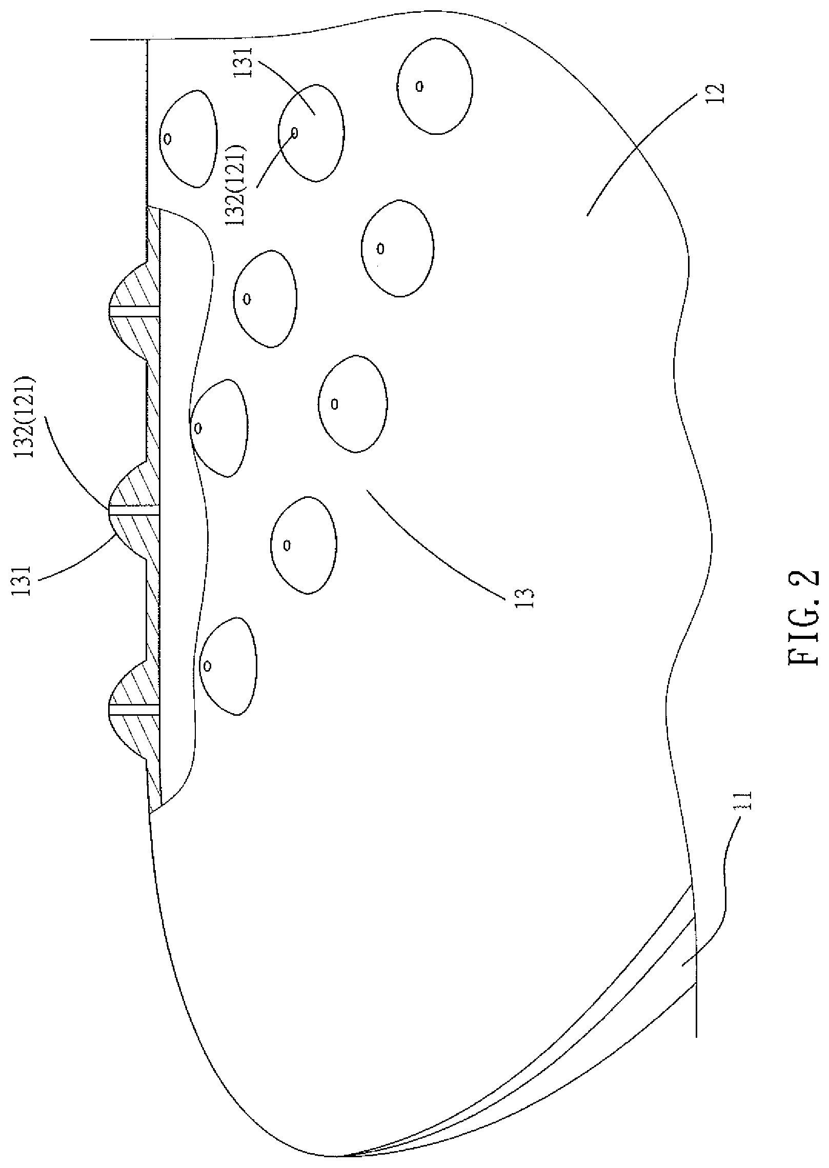
[0015] FIG. 2 is a partially side cross-sectional view of the shoe structure in accordance with the preferred embodiment of the present invention.
[0016] FIG. 3 is a schematic operational view of the shoe structure as shown in FIG. 2 in use.
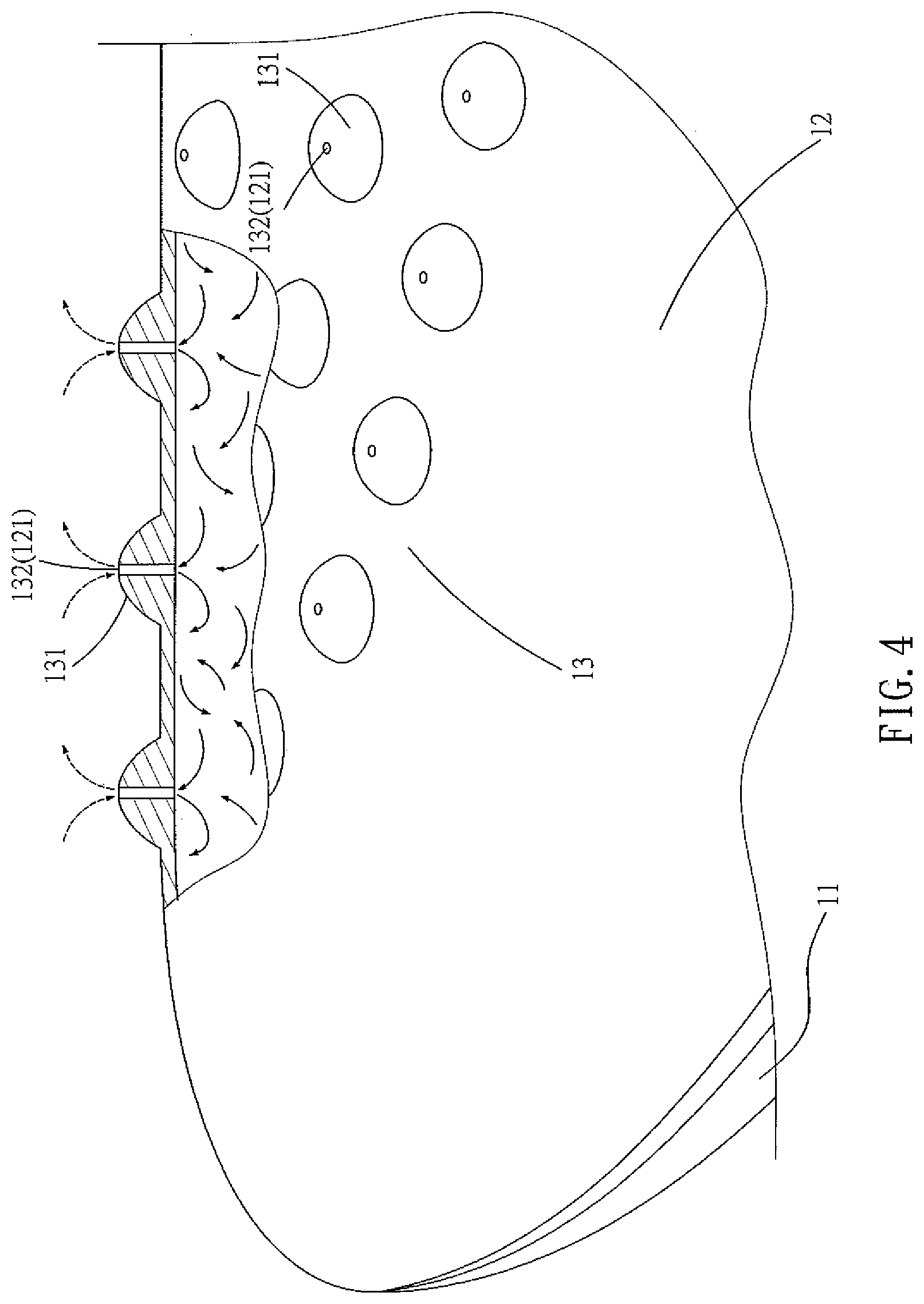
[0017] FIG. 4 is a schematic operational view of the shoe structure as shown in FIG. 2 in use.
[0018] FIG. 5 is a partially perspective view and a locally enlarged view of a shoe structure in accordance with another preferred embodiment of the present invention.
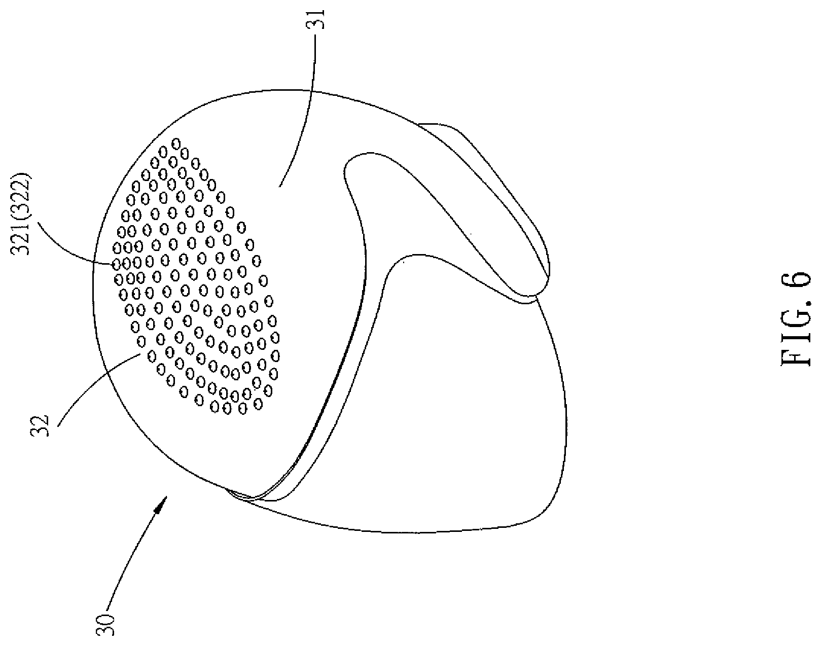
[0019] FIG. 6 is a perspective view showing the waterproof lining for a helmet.
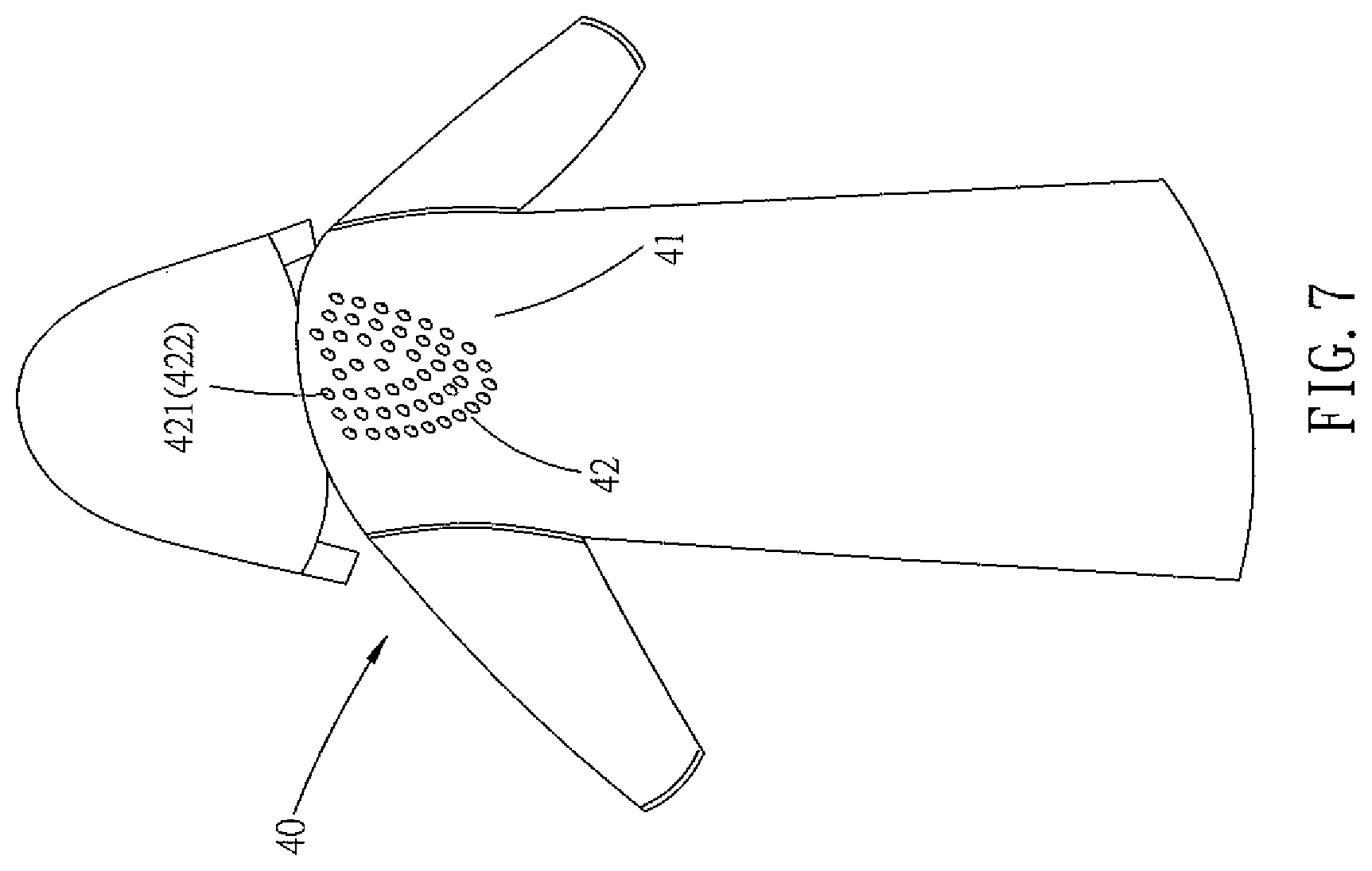
[0020] FIG. 7 is a perspective view showing the waterproof lining for a raincoat.
[0021] FIG. 8 is a partially perspective view of a conventional waterproof shoe structure in accordance with the prior art.
[0022] FIG. 9 is a cross-sectional view of the conventional waterproof shoe structure as shown in FIG. 8, wherein the hot wet air in the shoe structure is introduced through the air channels and is drained outward.
DETAILED DESCRIPTION OF THE INVENTION
[0023] Referring to the drawings and initially to FIGS. 1 and 2, a shoe structure 10 in accordance with the preferred embodiment of the present invention comprises a sole 11, a vamp 12 mounted on the sole 11, and a waterproof lining 13 mounted on the vamp 12.
[0024] The vamp 12 is provided with a plurality of vent holes 121.
[0025] The waterproof lining 13 has a surface provided with a plurality of convex portions 131 and a plurality of concave portions between the convex portions 131. Each of the convex portions 131 has various models. Each of the convex portions 131 is higher than each of the concave portions. Each of the convex portions 131 is provided with a through hole 132 connected to each of the vent holes 121 of the vamp 12. The through hole 132 of each of the convex portions 131 and each of the vent holes 121 of the vamp 12 are integrated to connect an inner space of the vamp 12 to an ambient environment, to provide a ventilating effect to the shoe structure 1.
[0026] In the preferred embodiment of the present invention, each of the convex portions 131 has a semispherical shape.
[0027] In the preferred embodiment of the present invention, the through hole 132 of each of the convex portions 131 is disposed at a vertical state.
[0028] In the preferred embodiment of the present invention, the through hole 132 extends downward from a central position of a top face of each of the convex portions 131.
[0029] In the preferred embodiment of the present invention, the through hole 132 of each of the convex portions 131 has a small diameter.
[0030] In the preferred embodiment of the present invention, each of the vent holes 121 extends through a whole thickness of the vamp 12, and the through hole 132 extends through a whole thickness of each of the convex portions 131.
[0031] In practice, referring to FIG. 3 with reference to FIGS. 1 and 2, when the rainwater drops, the rainwater directly flows down from the convex portions 131 to the concave portions of the waterproof lining 13, and will not stay on the convex portions 131. In addition, when the rainwater drops onto the through hole 132 of each of the convex portions 131, the rainwater does not enter the through hole 132 of each of the convex portions 131 by the capillary action which is an interaction of a surface tension (cohesion) and an adhesion. In such a manner, when the liquid touches the solid face, the molecule of the liquid (or the rainwater) and the molecule of the solid face (or the convex portions 131) produce an adhesion. When the adhesion between the liquid and the solid face is greater than the cohesion (the surface tension) of the liquid, the capillary action is produced, and the liquid is distributed on the solid face, so that the rainwater directly flows down along the convex portions 131 and does not infiltrate into the through hole 132 of each of the convex portions 131. Thus, the vamp 12 has a waterproof function by provision of the convex portions 131 of the waterproof lining 13.
[0032] Referring to FIG. 4 with reference to FIGS. 1 and 2, when the wearer is moving, the vamp 12 is moved, and the waterproof lining 13 is moved with the vamp 12. When the vamp 12 is compressed by an external force, the air in the inner space of the vamp 12 is forced to flow through each of the vent holes 121 of the vamp 12 and the through hole 132 of each of the convex portions 131, and is drained outward from the through hole 132 of each of the convex portions 131 into the ambient environment. When the vamp 12 is released and restored to the original state after the external force disappears, the air from the ambient environment is introduced through the through hole 132 of each of the convex portions 131 and each of the vent holes 121 of the vamp 12 into the inner space of the vamp 12. In such a manner, the vamp 12 has a ventilating function by provision of the convex portions 131 of the waterproof lining 13, thereby providing a comfortable sensation to the wearer when wearing the shoe structure 1. Thus, the shoe structure 10 has waterproof and ventilating functions by provision of the convex portions 131 of the waterproof lining 13.
[0033] Referring to FIG. 5, a shoe structure 10' in accordance with another preferred embodiment of the present invention comprises a sole 11', a vamp 12' mounted on the sole 11', and a waterproof lining 13' mounted on the vamp 12'. The waterproof lining 13 has a surface provided with a plurality of convex portions 131' and a plurality of concave portions between the convex portions 131'. Each of the convex portions 131' is provided with a through hole 132'. Preferably, each of the convex portions 131' has different configurations, such as hexagonal shape, conic shape, elliptical shape, triangular pyramid shape or the like.
[0034] Referring to FIG. 6, a helmet 30 comprises a shell 31 and a waterproof lining 32 mounted on the shell 31. The waterproof lining 32 has a surface provided with a plurality of convex portions 321 and a plurality of concave portions between the convex portions 321. Each of the convex portions 321 is provided with a through hole 322. Thus, the helmet 30 has waterproof and ventilating functions by provision of the convex portions 321 of the waterproof lining 32.
[0035] Referring to FIG. 7, a raincoat 40 comprises a coat back 41 and a waterproof lining 42 mounted on the coat back 41. The waterproof lining 42 has a surface provided with a plurality of convex portions 421 and a plurality of concave portions between the convex portions 421. Each of the convex portions 421 is provided with a through hole 422. Thus, the raincoat 40 has waterproof and ventilating functions by provision of the convex portions 421 of the waterproof lining 42.
[0036] Accordingly, the shoe structure has waterproof and ventilating functions by provision of the convex portions of the waterproof lining.
[0037] Although the invention has been explained in relation to its preferred embodiment(s) as mentioned above, it is to be understood that many other possible modifications and variations can be made without departing from the scope of the present invention. It is, therefore, contemplated that the appended claim or claims will cover such modifications and variations that fall within the scope of the invention.
* * * * *
D00000
D00001
D00002
D00003
D00004
D00005
D00006
D00007
D00008
D00009
XML
uspto.report is an independent third-party trademark research tool that is not affiliated, endorsed, or sponsored by the United States Patent and Trademark Office (USPTO) or any other governmental organization. The information provided by uspto.report is based on publicly available data at the time of writing and is intended for informational purposes only.
While we strive to provide accurate and up-to-date information, we do not guarantee the accuracy, completeness, reliability, or suitability of the information displayed on this site. The use of this site is at your own risk. Any reliance you place on such information is therefore strictly at your own risk.
All official trademark data, including owner information, should be verified by visiting the official USPTO website at www.uspto.gov. This site is not intended to replace professional legal advice and should not be used as a substitute for consulting with a legal professional who is knowledgeable about trademark law.