Variable Dither Control System For A Fluid Actuator
McBrien; Gary M. ; et al.
U.S. patent application number 16/028681 was filed with the patent office on 2020-01-09 for variable dither control system for a fluid actuator. The applicant listed for this patent is Hamilton Sundstrand Corporation. Invention is credited to Gary M. McBrien, James Saloio.
| Application Number | 20200011447 16/028681 |
| Document ID | / |
| Family ID | 67437545 |
| Filed Date | 2020-01-09 |
| United States Patent Application | 20200011447 |
| Kind Code | A1 |
| McBrien; Gary M. ; et al. | January 9, 2020 |
VARIABLE DITHER CONTROL SYSTEM FOR A FLUID ACTUATOR
Abstract
A fluid system has a fluid actuator that receives a fluid to cause movement of a component. A valve selectively controls the flow of fluid to the fluid actuator. A motor for the valve is provided with an electric voltage or current. A control applies a pulse width modulation variation to the supplied voltage or current. The control is operable to vary the pulse width modulation of the voltage or the current based upon conditions of the system. A mechanical system and a method are also disclosed.
| Inventors: | McBrien; Gary M.; (South Glastonbury, CT) ; Saloio; James; (Ludlow, MA) | ||||||||||
| Applicant: |
|
||||||||||
|---|---|---|---|---|---|---|---|---|---|---|---|
| Family ID: | 67437545 | ||||||||||
| Appl. No.: | 16/028681 | ||||||||||
| Filed: | July 6, 2018 |
| Current U.S. Class: | 1/1 |
| Current CPC Class: | F15B 13/043 20130101; F15B 13/044 20130101; H01F 7/081 20130101; F15B 13/0438 20130101; F15B 2211/427 20130101; F15B 13/0436 20130101; F15B 2211/328 20130101; F16H 61/0251 20130101; G05B 2219/42237 20130101; F16K 31/0675 20130101; F16H 2061/0255 20130101 |
| International Class: | F16K 31/06 20060101 F16K031/06; F16H 61/02 20060101 F16H061/02; H01F 7/08 20060101 H01F007/08 |
Claims
1. A fluid driven system comprising: a fluid actuator to receive a fluid to result in movement of a component; a valve for selectively controlling the flow of fluid to said fluid actuator, and a motor for said valve being provided with a voltage and an electric current; and a control for applying a pulse width modulation variation to said supplied voltage or current, and said control being operable to vary said pulse width modulation of the voltage or current based upon conditions of the system.
2. The fluid driven system as set forth in claim 1, wherein the frequency is lowered by the control should more accurate control of the component be desirable.
3. The fluid driven system as set forth in claim 1, wherein the frequency is varied across at least three levels.
4. The fluid driven system as set forth in claim 1, wherein said component is a variable vane for use in a gas turbine engine.
5. The fluid driven system as set forth in claim 4, wherein said fluid actuator is a reciprocating piston.
6. The fluid driven system as set forth in claim 1, wherein a motor for said includes an armature coil supplied by the current to, in turn, control a flow of fluid to the fluid actuator.
7. The fluid driven system as set forth in claim 1, wherein said motor controlling supply of fluid to said valve, said valve controlling the supply of fluid to said fluid actuator, with there being magnetic hysteresis at said motor, and mechanical hysteresis associated with both said valve and said fluid actuator, and said pulse width modulation reducing an effect of said magnetic hysteresis and said mechanical hysteresis of a positioning of said component.
8. The fluid driven system as set forth in claim 7, wherein a lowered frequency of pulse width modulation eliminates more of said magnetic and mechanical hysteresis than does a higher frequency.
9. The fluid driven system as set forth in claim 1, wherein said control operable to vary at least one of a duration, a width and a frequency of the pulse width modulation of the voltage or current.
10. A mechanical system comprising: a magnetic motor being supplied with a voltage and a current from a control, said control supplying said voltage or said current with a pulse width modulation; said magnetic motor controlling the supply of a fluid to a spool valve and said spool valve controlling the supply of fluid to a fluid actuator for a component; and said control varying the pulse width modulation of the voltage or the current based upon system conditions.
11. The mechanical system as set forth in claim 10, wherein a frequency of the pulse width modulation is lowered by the control should more accurate control of the component be desirable.
12. The mechanical system as set forth in claim 11, wherein the frequency is varied across at least three levels.
13. The mechanical system as set forth in claim 10, wherein said component is a variable vane for use in a gas turbine engine.
14. The mechanical system as set forth in claim 10, wherein said control operable to vary at least one of a duration, a width and a frequency of the pulse width modulation of the voltage or current.
15. A method of operating a fluid driven system comprising: operating a motor for a valve to control a flow of fluid to a fluid actuator, and said motor being provided with a voltage and a current; and and moving a component with said fluid actuator by applying pulse width modulation to said voltage or current, and said control varying said pulse width modulation of the current based upon conditions of the system.
16. The method as set forth in claim 14, wherein a frequency of the pulse width modulation is lowered by the control should more accurate control of the component be desirable.
17. The method as set forth in claim 16, wherein a lowered frequency eliminates more of magnetic and mechanical hysteresis than does a higher frequency.
18. The method as set forth in claim 15, wherein said component is a variable vane in a gas turbine engine.
19. The method as set forth in claim 17, wherein said fluid actuator is a reciprocating piston.
20. The method as set forth in claim 15, wherein said control varying at least one of a duration, a width and a frequency of the pulse width modulation of the voltage or current.
Description
BACKGROUND
[0001] This application relates to a control system that provides a variable dither to a voltage or current command to a fluid actuator.
[0002] Fluid actuators are known in many modern applications. As one example, a piston may be driven with hydraulic fluid to change the position or orientation of a mechanical component. Also, fluid actuators may be utilized to drive fluid systems such as hydraulic motors.
[0003] With modern controls, careful positioning of the actuator becomes desirable. There is a challenge with many modern systems due to an effect known as hysteresis effects. In particular, magnetic systems exhibit a hysteresis characteristic which can cause the actual positioning of the component dynamic response to be different from that which is desired.
[0004] There is also mechanical hysteresis which can be present in actuator systems. As an example, the movement of a hydraulic piston, such as one with seals that cause mechanical resistance can be impeded from moving to the desired or expected position.
[0005] It is known in prior art that providing "dither" by utilizing pulse width modulation (PWM) on a voltage or current supply or, by other means, to a motor or other drive for a fluid system, the performance of the system can be enhanced. A PWM supply rapidly perturbs applied current such that the fluid actuator components undergo small and repeated movements in opposed directions, usually about some operating point.
[0006] This can reduce the effect of the hysteresis. However, the use of the dither itself can raise some undesirable characteristics such as noise, wear, and unacceptable output disturbance.
SUMMARY
[0007] A fluid system has a fluid actuator that receives a fluid to cause movement of a component. A valve selectively controls the flow of fluid to the fluid actuator. A motor for the valve is provided with an electric voltage or current. A control applies a pulse width modulation variation to the supplied voltage or current. The control is operable to vary the pulse width modulation of the voltage or the current based upon conditions of the system. A mechanical system and a method are also disclosed.
[0008] These and other features may be best understood from the following drawings and specification.
BRIEF DESCRIPTION OF THE DRAWINGS
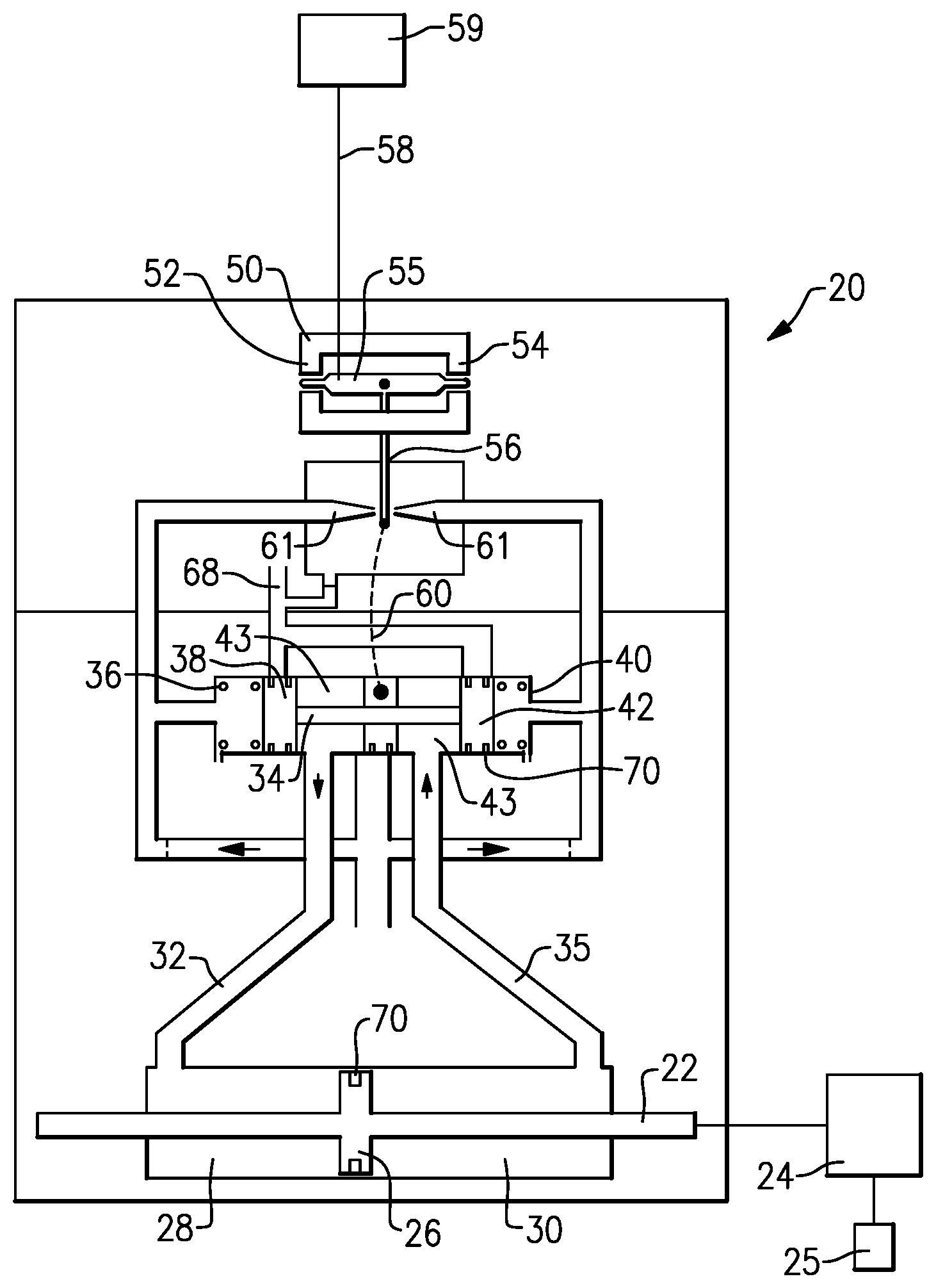
[0009] FIG. 1 schematically shows a first fluid system.
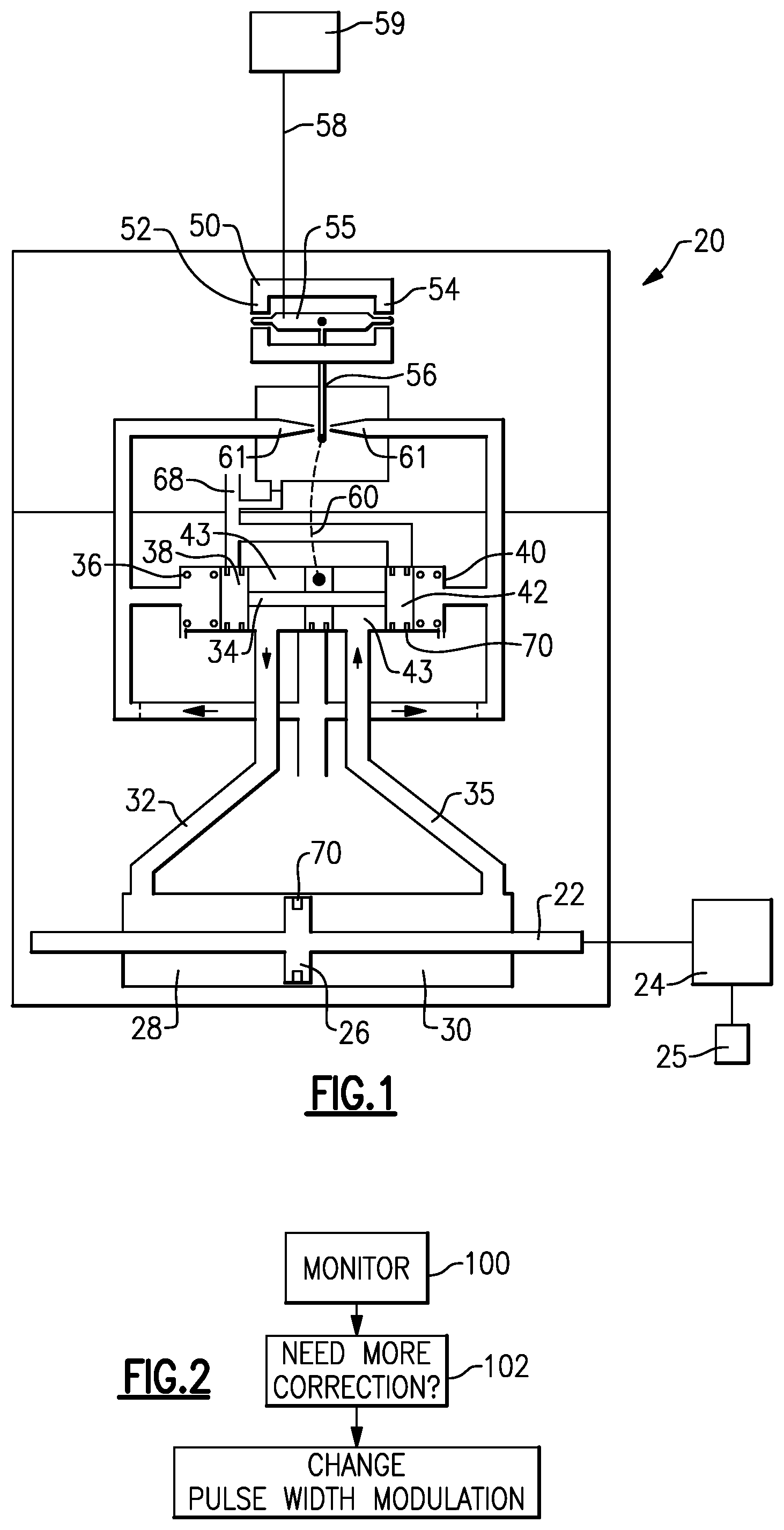
[0010] FIG. 2 shows a flowchart for a control feature of this disclosure.
DETAILED DESCRIPTION
[0011] FIG. 1 shows an example fluid system 20. Fluid system 20 controls an actuator piston rod 22 which is connected to drive or position a component 24. Component 24 can be any number of mechanical components. In one specific embodiment, the component 24 may position a variable vane assembly on a gas turbine engine. As the piston rod 22 is driven to translate, it may drive a mechanism such as a synchronization ring and other interrelated components to, in turn, change the position of a variable vane, shown schematically at 25. The connections and reasons for changing the angular orientation of the variable vane 25 may be as known. However, a control system, as will be described, is unique to this disclosure.
[0012] The piston rod 22 drives with a piston 26, which is moved to translate by fluid driven into chambers 28 or 30. Supply/return lines 32/35 connect the chambers 28/30 to a spool valve 34. Spool valve 34 has springs 36 and 40 positioning lands 38 and 42. Fluid is driven into chambers 43 between the lands 42 and 38 to drive the spool valve and to selectively communicate return or supply lines to, in turn, drive the actuator 22.
[0013] A drive motor 50 incorporates magnets 52 and 54 to change an angular attraction/opposition for an armature winding 55. Winding 55 is supplied with current and voltage from a supply 58. Supply 58 is controlled by a control 59.
[0014] As the current and voltage are controlled to the two sides of the armature, an end effector 56 is caused to pivot between flapper nozzles 61. As the end effector 56 pivots, it either restricts or opens respective nozzles 61.
[0015] This, in turn, drives the position of the spool valve 34 to change. A feedback spring 60 connects the end effector to valve 34
[0016] The operation of the system as described to this point is generally as known. In addition, while the particular fluid system 20 is disclosed, the teachings of the control of this disclosure can extend to many other types of systems wherein a fluid actuator motor receives a control current and/or voltage to control a valve position.
[0017] As mentioned above, in the prior art, there is knowledge that there is hysteresis, particularly in the drive motor 50. However, within the spool valve 34, and even the actuator rod 22, there may also be mechanical hysteresis, such as may occur by movement along seals 70, or with regard to the reaction of the springs 36 and 40.
[0018] In the prior art, a voltage/current supply 59 was utilized with a suitably high frequency pulse width modulation mechanism to rapidly cycle the applied voltage on and off, resulting in the application of a steady current while minimizing heat and power dissipation in the controlling device.
[0019] Applicant has recognized that the use of the pulse width modulation control at a lower frequency, to effectively provide "dithering," or a repeated perturbation of the position about some operating point, has efficiency losses as to energy, and also may result in undesirable wear.
[0020] Thus, as shown in the flowchart of FIG. 2, in a broad method of this disclosure, the control 59 monitors operation of the overall system 20 at step 100. The question is asked whether increased correction of the position is necessary. If so, then the frequency and/or the width of the pulses of a pulse width modulation control can be lowered, at the same time the applied voltage is increased or decreased. With the lowering of the frequency, the magnetic perturbations of the armature magnetic field, and the mechanical perturbations of the driven system, such as here, at the pivoting end of effector 56 will become more pronounced. This, in turn, can result in more pronounced movement of the spool valve 34 and the actuator rod 22. This will provide better elimination of the hysteresis effect and more accurate overall positioning. However, as mentioned above, there are undesirable losses due to use of the dithering, especially as the frequency is lowered. A combination of higher voltage with smaller pulse width or lower pulse width modulation frequency or some combination of the two will increase the perturbations and dither.
[0021] As such, in situations where the increased correction, or fine positioning, is not as necessary, the control will move the pulse width modulation to a higher frequency, reducing the magnetic and/or mechanical dither.
[0022] In one embodiment, there may be an infinite number of steps of variation in the pulse width modulation frequency and voltage control. Five such steps are disclosed below. However, more or fewer steps can also be utilized. In one example, at least three distinct levels are contemplated.
[0023] At a highest frequency level, and/or a lowest applied voltage and wide pulse width, there is the lowest ripple, the least noise, the least wear, and the most efficient use of power. Such a first step may be utilized when accurate positioning is not as necessary. Such as when gross movement is being achieved.
[0024] At a second step, the frequency is lowered somewhat from the first step, and/or the applied voltage is raised and pulse width is reduced. Such a step has a greater "ripple" or variation, and removes magnetic hysteresis effects such as from actuator 50. This is accomplished by having a perturbation in the magnetic field that exceeds the magnetic hysteresis band such that the commanded current results in a commanded magnetic field that oscillates around the hysteresis band in a manner known to reduce the effects of hysteresis in prior art.
[0025] A third step may have still higher voltage/more narrow pulse width, and/or lower frequency from the second step. The ripple is larger and would tend to remove the effect of magnetic hysteresis and also mechanical hysteresis at the spool valve 34, due to the dithering effect of the implied current.
[0026] At a still higher voltage/more narrow pulse width and/or a lower frequency, the ripple is becoming larger. The benefits as mentioned in three are all achieved, however, there also tends to provide mechanical dithering, thereby reducing friction and hysteresis in the actuator. As dynamic friction in a system, as would be experienced when the mechanical surfaces in contact are moving, is reduced compared to static friction when the the surfaces are not moving or moving very slowly, the hysteresis is reduced.
[0027] At step 5, an even lower frequency may be utilized. The dithering movement begins to be noticeable in the target system. Still, the target system will tend to oscillate about the desired position, and there is a reduction in frictional effect as described in the step above, due to the resulting lower dynamic friction rather than static friction.
[0028] In a modern control system, there are various times in the control operation when various aspects of performance are desired to be optimized in the system, variable with time, operating mode, output position or condition, etc. with this system, dither can be modulated instantaneously in real time, varying in duration and/or, amplitude, to suit the needs at that moment
[0029] As examples, when the system output is moving rapidly, and fine positioning accuracy is not required, during gross movements from one position to another, the dither could be small. If a system has arrived close to a desired position the dither can be increased to allow the system to position very accurately, then when the system has arrived very close to the desired position, the dither can be reduced again. Likewise when the system output is at a point where greater positioning accuracy is not needed, the dither can be small.
[0030] A method of operating a fluid driven system includes the steps of operating a valve for selectively controlling a flow of fluid to a fluid actuator. The valve is provided with an electric voltage and current. A component is moved by the fluid actuator. A control applies pulse width modulation to the voltage or current. The control varies at least one of an applied voltage, pulse width or frequency of the pulse width modulation based upon conditions of the system.
[0031] A control programmed to achieve the above variation may be incorporated into a full-authority digital electronic control for an associated engine, or may be a separate control.
[0032] Although an embodiment of this invention has been disclosed, a worker of ordinary skill in this art would recognize that certain modifications would come within the scope of this disclosure. For that reason, the following claims should be studied to determine the true scope and content of this disclosure.
* * * * *
D00000
D00001
XML
uspto.report is an independent third-party trademark research tool that is not affiliated, endorsed, or sponsored by the United States Patent and Trademark Office (USPTO) or any other governmental organization. The information provided by uspto.report is based on publicly available data at the time of writing and is intended for informational purposes only.
While we strive to provide accurate and up-to-date information, we do not guarantee the accuracy, completeness, reliability, or suitability of the information displayed on this site. The use of this site is at your own risk. Any reliance you place on such information is therefore strictly at your own risk.
All official trademark data, including owner information, should be verified by visiting the official USPTO website at www.uspto.gov. This site is not intended to replace professional legal advice and should not be used as a substitute for consulting with a legal professional who is knowledgeable about trademark law.