Valve For Bypass Conduit
Fiorenza; Francesco
U.S. patent application number 16/504007 was filed with the patent office on 2020-01-09 for valve for bypass conduit. This patent application is currently assigned to Smart RS Inc.. The applicant listed for this patent is Smart RS Inc.. Invention is credited to Francesco Fiorenza.
| Application Number | 20200011438 16/504007 |
| Document ID | / |
| Family ID | 67184850 |
| Filed Date | 2020-01-09 |

| United States Patent Application | 20200011438 |
| Kind Code | A1 |
| Fiorenza; Francesco | January 9, 2020 |
VALVE FOR BYPASS CONDUIT
Abstract
The present disclosure provides a valve for a respiratory bypass conduit, the valve further comprised of an inner frame that provides rigidity to a flexible outer seal. The inner frame has guiding flanges to guide the valve within he conduit, and a hinge portion to be secured within a slot of the conduit. Together, the hinge and the guiding flanged help the valve move from a first position to a second position. The present disclosure also provides for a method of assembling the valve for respiratory bypass conduit, whereby the inner frame is aligned with and inserted into the outer seal until a peripheral gap of the outer seal substantially houses the inner frame and an inner periphery of the inner frame surrounds a recessed portion of the outer seal to secure the outer seal in the correct orientation relative to the inner frame.
| Inventors: | Fiorenza; Francesco; (Ottawa, CA) | ||||||||||
| Applicant: |
|
||||||||||
|---|---|---|---|---|---|---|---|---|---|---|---|
| Assignee: | Smart RS Inc. Ottawa CA |
||||||||||
| Family ID: | 67184850 | ||||||||||
| Appl. No.: | 16/504007 | ||||||||||
| Filed: | July 5, 2019 |
| Current U.S. Class: | 1/1 |
| Current CPC Class: | F16K 1/205 20130101; F16K 11/0743 20130101; F16K 15/03 20130101; F16K 11/052 20130101; A61M 16/208 20130101 |
| International Class: | F16K 11/074 20060101 F16K011/074 |
Foreign Application Data
| Date | Code | Application Number |
|---|---|---|
| Jul 5, 2018 | CA | 3010479 |
Claims
1. A valve for a bypass conduit, the seal comprising: a rigid inner frame having an opening at a front end and a hinge at a rear end; and, a flexible outer seal connected to the inner frame, the flexible outer seal defining a peripheral gap to substantially house the inner frame, wherein the valve is movable from a first position to a second position on the bypass conduit.
2. The valve of claim 1 wherein the inner frame is further comprised of first and second arms.
3. The valve of claim 1 wherein the inner frame is further comprised of two guiding flanges that make contact with the bypass conduit to keep the valve aligned from the first position to the second position.
4. The valve of claim 2 wherein the first and second arms terminate in first and second connectors, each of the first and second connectors having a sloping front face angled to facilitate receiving the flexible outer seal.
5. The valve of claim 1 wherein the flexible outer seal is further comprised of a recessed portion.
6. The valve of claim 5 wherein the recessed portion has a first circular side and a second straight side.
7. The valve of claim 1 wherein the flexible outer seal is further comprised of a peripheral gap.
8. A method of assembling a valve for a bypass conduit, the steps comprising: aligning a recessed portion of the outer seal with an inner periphery of the inner frame; inserting first and second connectors of the inner frame into a peripheral gap of the outer seal; making contact with sloping front faces of the inner frame to an inner wall of the recessed portion to facilitate insertion of the inner frame into the outer seal; and, continuing to insert the inner frame within the outer seal until the peripheral gap of the outer seal substantially houses the inner frame and an inner periphery of the inner frame surrounds the recessed portion and therefore secures the outer seal in the correct orientation relative to the inner frame.
Description
FIELD
[0001] The invention relates to the field of bypass conduits, and more specifically to improved valves for respiratory bypass conduits.
SUMMARY
[0002] In an aspect, the present disclosure provides a valve for a bypass conduit, the seal comprising a rigid inner frame having an opening at a front end and a hinge at a rear end; and, a flexible outer seal connected to the inner frame, the flexible outer seal defining a peripheral gap to substantially house the inner frame, wherein the valve is movable from a first position to a second position on the bypass conduit.
[0003] In another aspect, the present disclosure provides a method of assembling a valve for a bypass conduit, the steps comprising aligning a recessed portion of the outer seal with an inner periphery of the inner frame; inserting first and second connectors of the inner frame into a peripheral gap of the outer seal; making contact with sloping front faces of the inner frame to an inner wall of the recessed portion to facilitate insertion of the inner frame into the outer seal; and, continuing to insert the inner frame within the outer seal until the peripheral gap of the outer seal substantially houses the inner frame and an inner periphery of the inner frame surrounds the recessed portion and therefore secures the outer seal in the correct orientation relative to the inner frame.
BRIEF DESCRIPTION OF THE DRAWINGS
[0004] The following figures serve to illustrate various embodiments of features of the disclosure. These figures are illustrative and are not intended to be limiting.
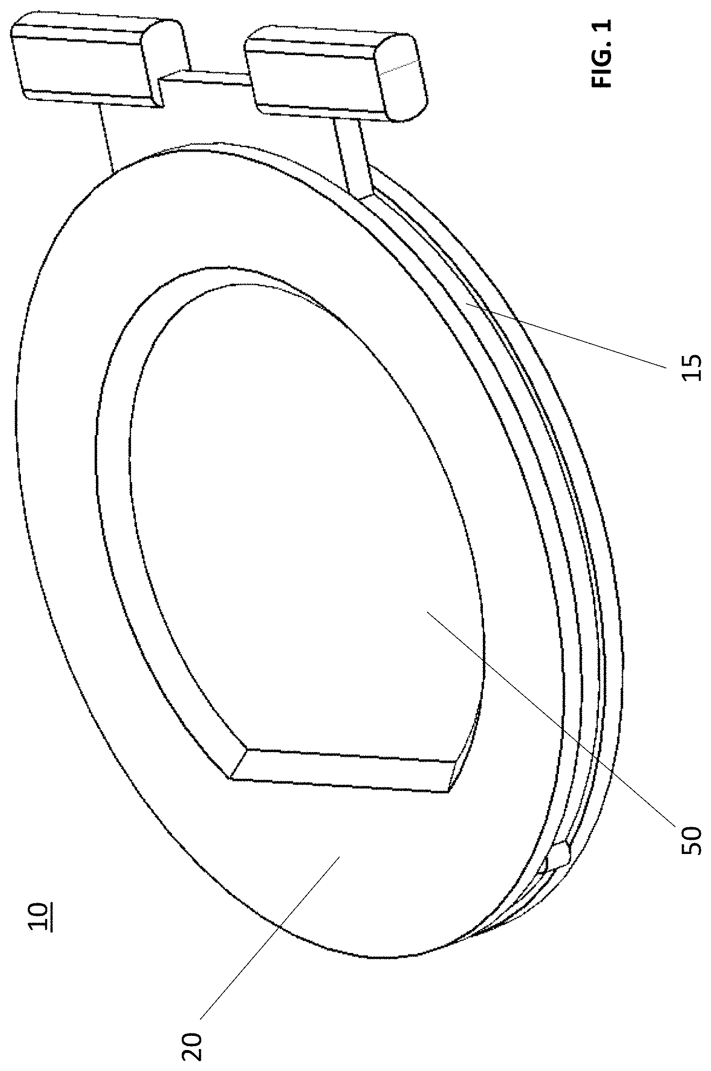
[0005] FIG. 1 is a perspective view of a valve according to an embodiment of the present disclosure;
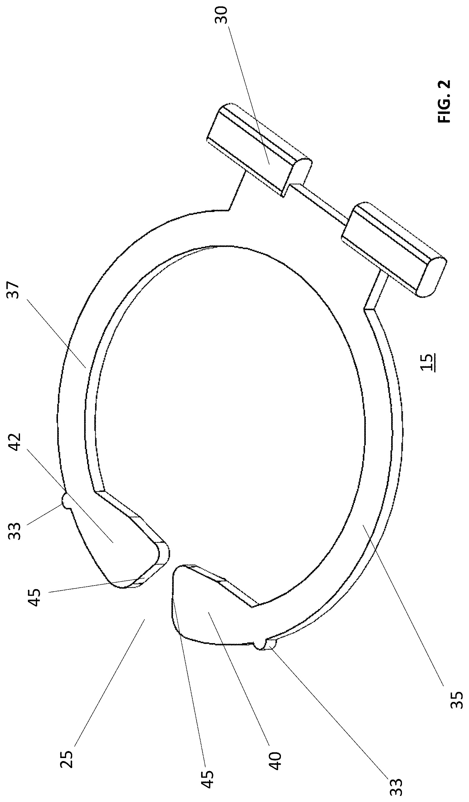
[0006] FIG. 2 is a perspective view of an inner frame of the valve according to an embodiment of the present disclosure;
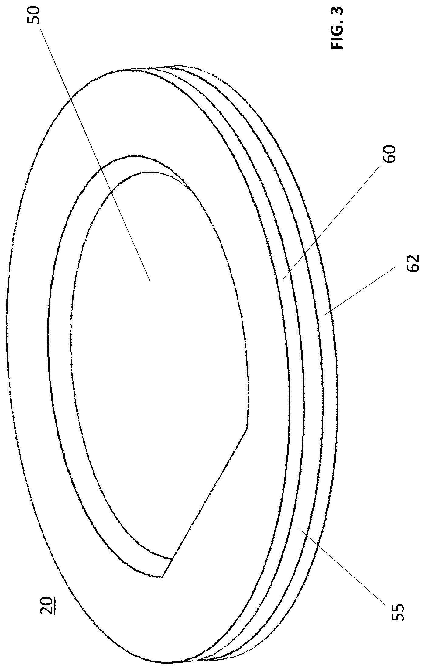
[0007] FIG. 3 is a perspective view of a flexible outer seal of the valve according to an embodiment of the present disclosure;
[0008] FIG. 4 is a top view of the valve according to an embodiment of the present disclosure;
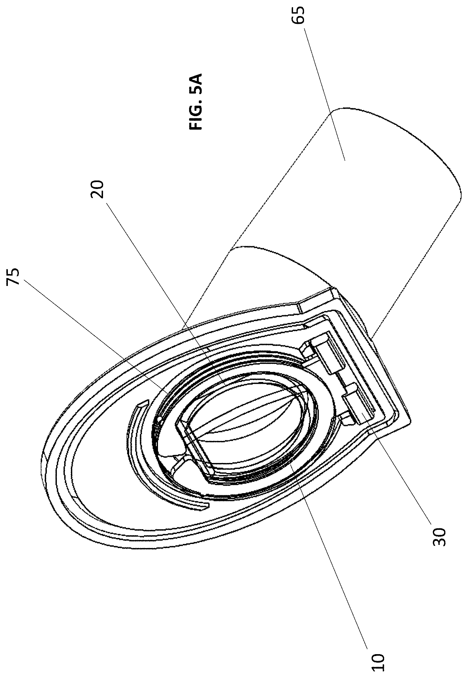
[0009] FIG. 5A is a perspective cross-sectional view of the valve within a portion of a bypass conduit according to an embodiment of the present disclosure; and,
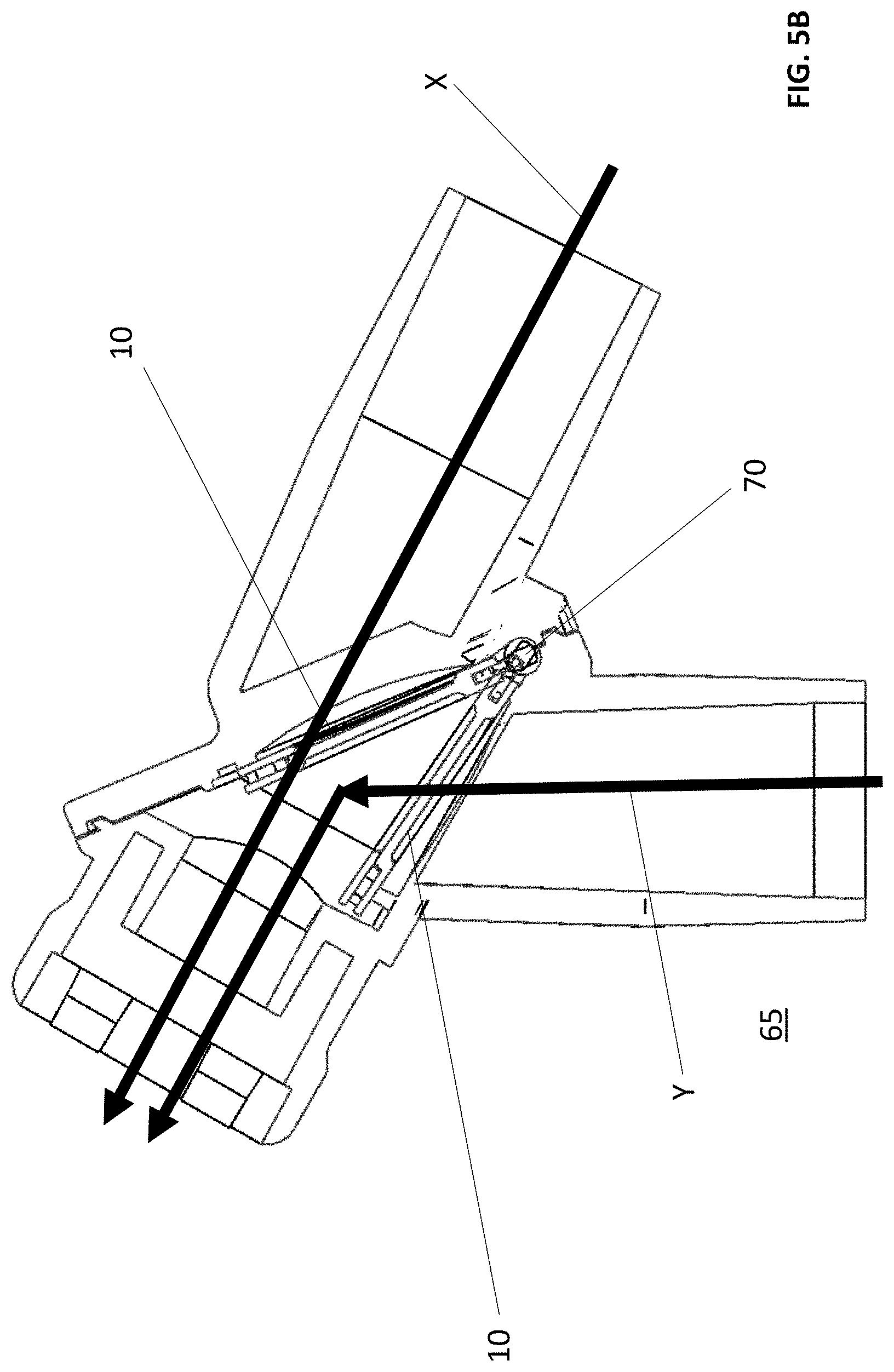
[0010] FIG. 5B is a front cross-sectional view of the valve within the bypass conduit according to an embodiment of the present disclosure.
DETAILED DESCRIPTION
[0011] The following embodiments are merely illustrative and are not intended to be limiting. It will be appreciated that various modifications and/or alterations to the embodiments described herein may be made without departing from the disclosure and any modifications and/or alterations are within the scope of the contemplated disclosure.
[0012] With reference to FIGS. 1, 2 and 3 and according to an embodiment of the present disclosure, a valve 10 for use in a respiratory bypass conduit is disclosed. The valve 10 is comprised of a rigid inner frame 15 that provides rigidity to a flexible outer seal 20. The inner frame 15 is defined by a front end having an opening 25, and a rear end having a hinge 30. The hinge 30 is designed to mate with a corresponding slot (not shown) of the bypass conduit to move the valve 10 from a first position to a second position. The first position is the area where the valve 10 covers an aperture in a first portion of the valve conduit, and the second position is the area where the valve 10 covers another aperture in a second portion of the valve conduit. The inner frame is further comprised of two guiding flanges 33 that make contact with an inner portion of a conduit (not shown) to keep the valve 10 aligned and moving between the first and second positions. Indeed, the guiding flanges 33 create the requisite friction to maintain the correct pivoting of the valve 10. The inner frame 15 is also comprised of first and second arms 35, 37 that are substantially circularly shaped. First and second arms 35, 37 terminate in first and second connectors 40, 42, respectively. First and second connectors 40, 42 each have a sloping front face 45, the sloping front face 45 angled to facilitate receiving the outer seal 20 during the assembly of the valve 10. The assembly of the valve 10 will be further disclosed below. The inner periphery of the inner frame 15 has a shape that corresponds to a recessed portion 50 of the outer seal 20. Indeed, the inner periphery of the inner frame 15 surrounds and encloses a recessed portion 50 of the outer seal 20 such that the outer seal 20 stays in the same position and orientation relative to the inner frame 15. The recessed portion 50 has a first circular side and a second straight side, as specifically shown in FIG. 3. The outer seal 20 is further comprised of a peripheral gap 55 to substantially house the first and second arms 35, 37 and first and second connectors 40, 42 of the inner frame 15. The peripheral gap 55 is defined as the space surrounding the recessed portion 50 of the outer seal 20 and in between upper and lower flaps 60, 62 of the outer seal 20.
[0013] With reference to FIG. 4 and according to an embodiment of the present disclosure, the outer seal 20 is shown substantially surrounding the inner frame 15. The hinge 30 is shown protruding from the outer seal 20 to contact a slot (not shown) of the bypass conduit. The guiding flanges 33 are also shown protruding from the periphery of the outer seal 20 to guide the valve 10 from the first position to the second position in the bypass conduit. As shown, the recessed portion 50 of the seal 20 is surrounded and enclosed by the inner periphery of the inner frame 15. The first and second arms 35, 37 of the inner frame 15 are contained within the peripheral gap (not shown) of the outer seal 20. To assemble the valve 10, the outer seal 20 is positioned proximate the front end of the inner frame 15, and the shape of the recessed portion 50 of the outer seal 20 is oriented in the same manner as the shape of the inner periphery of the inner frame 15. The first and second connectors 40, 42 of the inner frame 15 are then inserted into the peripheral gap (not shown) of the outer seal 20 until the sloping front faces 45 of the first and second connectors 40, 42 make contact with an inner wall (not shown) of the recessed portion 50. The sloping front faces 45 help facilitate the continued insertion of the recessed portion 50 of the outer seal 20 into the opening 20 of the inner frame 15. Indeed, the recessed portion 50 of the outer seal 20 compresses to fit through the opening 20 of the inner frame 15 until the recessed portion 50 has been completely inserted through the opening 20. At this point, the inner periphery of the inner frame 15 surrounds the recessed portion 50 and therefore secures the outer seal 20 in the correct orientation relative to the inner frame 15. In the assembled state of the valve 10, the peripheral gap 55 of the outer seal 20 substantially houses the inner frame 15.
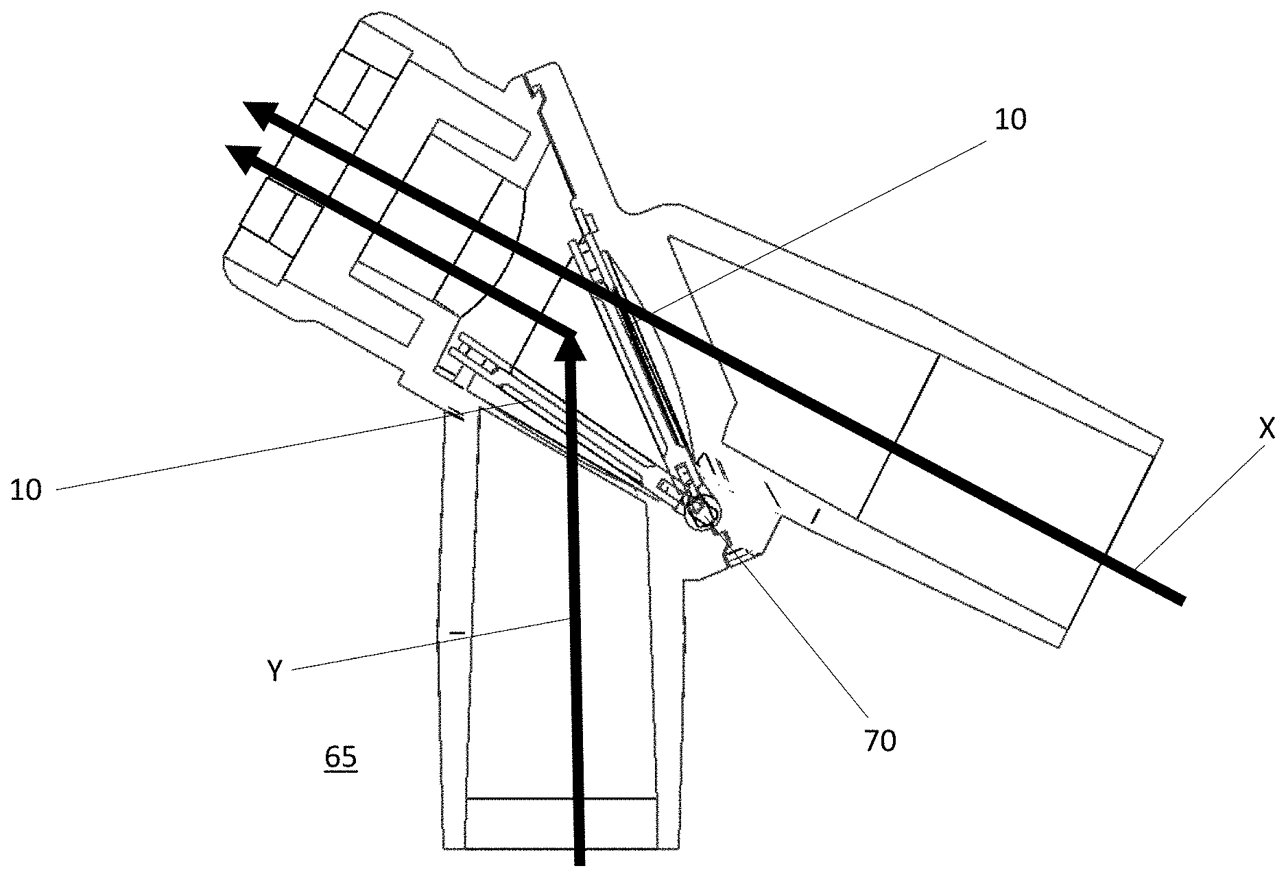
[0014] With reference to FIGS. 5A and 5B and according to an embodiment of the present disclosure, the valve 10 is shown positioned in a bypass conduit 65. Indeed, the hinge 30 of the valve 10 is secured into the slot 70 of the bypass conduit 60. With specific reference to FIG. 5B, the valve 10 is shown moving from a first position to a second position within the bypass conduit 65. A worker skilled in the art would appreciate that when the valve 10 is in the first position, air can flow through the bypass conduit 65 in direction X, while when the valve is in the second position, air can flow through the bypass conduit in direction Y. The bypass conduit 65 is further comprised of a raised ridge 75 to improve the seal between the outer seal 20 and the bypass conduit 65.
[0015] Many modifications of the embodiments described herein as well as other embodiments may be evident to a person skilled in the art having the benefit of the teachings presented in the foregoing description and associated drawings. It is understood that these modifications and additional embodiments are captured within the scope of the contemplated disclosure which is not to be limited to the specific embodiment disclosed.
* * * * *
D00000
D00001
D00002
D00003
D00004
D00005
D00006
XML
uspto.report is an independent third-party trademark research tool that is not affiliated, endorsed, or sponsored by the United States Patent and Trademark Office (USPTO) or any other governmental organization. The information provided by uspto.report is based on publicly available data at the time of writing and is intended for informational purposes only.
While we strive to provide accurate and up-to-date information, we do not guarantee the accuracy, completeness, reliability, or suitability of the information displayed on this site. The use of this site is at your own risk. Any reliance you place on such information is therefore strictly at your own risk.
All official trademark data, including owner information, should be verified by visiting the official USPTO website at www.uspto.gov. This site is not intended to replace professional legal advice and should not be used as a substitute for consulting with a legal professional who is knowledgeable about trademark law.