Device And Method For Fan Speed Control
LI; Yung-Fu
U.S. patent application number 16/030251 was filed with the patent office on 2020-01-09 for device and method for fan speed control. The applicant listed for this patent is QUANTA COMPUTER INC.. Invention is credited to Yung-Fu LI.
| Application Number | 20200011339 16/030251 |
| Document ID | / |
| Family ID | 63914907 |
| Filed Date | 2020-01-09 |


| United States Patent Application | 20200011339 |
| Kind Code | A1 |
| LI; Yung-Fu | January 9, 2020 |
DEVICE AND METHOD FOR FAN SPEED CONTROL
Abstract
The present disclosure describes devices and methods that include a heartbeat signal for detecting an abnormality in the control of a fan for an electronic system. A fan controller can assume control of a fan over a fan speed control circuit in response to the abnormality. Control of the fan by the fan controller can eliminate or reduce overheating within the system caused by improper fan speed, in response to the abnormality.
| Inventors: | LI; Yung-Fu; (Taoyuan City, TW) | ||||||||||
| Applicant: |
|
||||||||||
|---|---|---|---|---|---|---|---|---|---|---|---|
| Family ID: | 63914907 | ||||||||||
| Appl. No.: | 16/030251 | ||||||||||
| Filed: | July 9, 2018 |
| Current U.S. Class: | 1/1 |
| Current CPC Class: | G06F 1/20 20130101; F04D 27/001 20130101; F04D 27/004 20130101; G06F 1/206 20130101 |
| International Class: | F04D 27/00 20060101 F04D027/00 |
Claims
1. A method of controlling a fan within an electronic system, comprising: monitoring a heartbeat signal indicating normal operation of the electronic system; detecting a discrepancy in the heartbeat signal; and controlling the fan according to a safe fan speed in response to the discrepancy.
2. The method of claim 1, wherein the heartbeat signal is generated by a fan speed control circuit of the electronic system, and the heartbeat signal indicates normal operation of the fan speed control circuit.
3. The method of claim 2, wherein the electronic system is a computer system, and the fan speed control circuit is a baseboard management controller.
4. The method of claim 2, further comprising setting the safe fan speed by the fan speed control circuit prior to detecting the discrepancy.
5. The method of claim 4, wherein the safe fan speed is less than full speed.
6. The method of claim 4, wherein the safe fan speed is set at startup of the computer system, at reset of the computer system, or both.
7. The method of claim 1, wherein the heartbeat signal is periodic, and the discrepancy is a lack of the heartbeat signal during at least one period, during two or more sequential periods, or during two or more non-sequential periods.
8. The method of claim 1, wherein the heartbeat signal is embedded within a fan speed control signal or separate from the fan speed control signal.
9. The method of claim 1, further comprising: determining that the discrepancy in the heartbeat signal has not been corrected and continuing the controlling of the fan according to the safe fan speed, in response to the determination.
10. An electronic system comprising: a fan speed control circuit configured to generate a heartbeat signal indicating normal operation of the fan speed control circuit; and a fan module comprising a fan controller and a fan, the fan controller being configured to detect a discrepancy in the heartbeat signal and control the fan according to a safe fan speed, in response to the discrepancy.
11. The electronic system of claim 10, wherein the electronic system is a computer system, and the fan speed control circuit is a baseboard management controller.
12. The electronic system of claim 11, wherein the baseboard management controller is configured to set the safe fan speed prior to the fan controller detecting the discrepancy.
13. The electronic system of claim 12, wherein the safe fan speed is less than full speed.
14. The electronic system of claim 12, wherein the safe fan speed is set at startup of the computer system, at reset of the computer system, or both.
15. The electronic system of claim 10, wherein the heartbeat signal is periodic, and the discrepancy is a lack of the heartbeat signal during at least one period, during two or more sequential periods, or during two or more non-sequential periods.
16. A method of controlling a fan module for cooling a computer system, comprising: generating, by a fan speed control circuit of the computer system, a fan speed control signal based on one or more parameters corresponding to heat generated within the computer system; generating, by the fan speed control circuit, a heartbeat signal indicating normal operation of the fan speed control circuit; controlling, by a fan controller of the fan module, a speed of a fan of the fan module based on the fan speed control signal; monitoring, by the fan controller, the heartbeat signal; detecting, by the fan controller, a discrepancy in the heartbeat signal based on the monitoring; and controlling, by the fan controller, the speed of the fan based on a safe fan speed in place of the fan speed control signal in response to the discrepancy.
17. The method of claim 16, further comprising: determining, by the fan controller, that the discrepancy in the heartbeat signal has not been corrected; and continuing, by the fan controller, the controlling of the fan according to the safe fan speed in response to the determination.
18. The method of claim 16, further comprising: determining, by the fan controller, that the discrepancy in the heartbeat signal has been corrected; and resuming, by the fan controller, controlling of the fan according to the fan speed control signal, in response to the determination.
19. The method of claim 16, further comprising setting the safe fan speed, by the fan speed control circuit, prior to the fan controller detecting the discrepancy.
20. The method of claim 16, wherein the safe fan speed is full speed.
Description
FIELD OF THE INVENTION
[0001] The present invention relates to cooling fans, and more specifically, to the control of a cooling fan in response to the lack of a control signal.
BACKGROUND
[0002] Fans are often required in various electronic systems that generate heat to cool the systems. The speed of the fan typically is controlled by a fan speed control circuit. For example, in computer systems, such as server systems, there often is a baseboard management controller (BMC) that generates a fan speed control signal. The fan speed control signal is then sent to a fan controller within a fan module. The fan controller dynamically controls the fan speed based on the fan speed control signal to cool the computer system, in addition to saving power consumption and reducing noise.
[0003] In the event that the hardware, firmware, or software of the fan speed control circuit fails (for example, in the BMC), the fan may stop altogether, or keep running at a constant speed that is insufficient for cooling the electronic system. This can lead to the electronic system hanging due to overheating. In a worst case scenario, improper fan speed control can even lead to permanent damage to the system.
[0004] Accordingly, there is a need for devices and methods that overcome the foregoing drawbacks.
SUMMARY
[0005] The various embodiments concern devices and methods for controlling a fan in the event of an abnormality in the normal control of the fan.
[0006] The various embodiments further concern a heartbeat signal that is monitored by a fan controller. In the event of a discrepancy in the heartbeat signal, the fan controller assumes control over the fan.
[0007] A method of controlling a fan within an electronic system, according to a first embodiment, includes monitoring a heartbeat signal. The heartbeat signal indicates the normal operation of the electronic system. The method further includes detecting a discrepancy in the heartbeat signal based on the monitoring. The method also includes controlling the fan according to a safe fan speed in response to the discrepancy.
[0008] In some implementations, the heartbeat signal can be generated by a fan speed control circuit of the electronic system. In which case, the heartbeat signal indicates normal operation of the fan speed control circuit.
[0009] In some implementations, the electronic system can be a computer system, and the fan speed control circuit can be a baseboard management controller.
[0010] In some implementations, the method can also include setting the safe fan speed by the fan speed control circuit prior to detecting the discrepancy.
[0011] In some implementations, the safe fan speed can be less than full speed, or can be full speed.
[0012] In some implementations, the safe fan speed can be set at startup of the computer system, at reset of the computer system, or both.
[0013] In some implementations, the heartbeat signal can be periodic; and the discrepancy can be a lack of the heartbeat signal during at least one period, during two or more sequential periods, or during two or more non-sequential periods.
[0014] In some implementations, the heartbeat signal can be embedded within a fan speed control signal.
[0015] In some implementations, the method can include determining that the discrepancy in the heartbeat signal has not been corrected, and continuing the controlling of the fan according to the safe fan speed in response to the determination.
[0016] A method of controlling a fan module for cooling a computer system, according to a second embodiment, includes a fan speed control circuit of the computer system generating a fan speed control signal that is based on one or more parameters corresponding to heat generated within the computer system. The method further includes the fan speed control circuit generating a heartbeat signal indicating normal operation of the fan speed control circuit. The method also includes a fan controller of the fan module controlling a speed of a fan of the fan module based on the fan speed control signal. The method additionally includes the fan controller monitoring the heartbeat signal. The method also includes the fan controller detecting a discrepancy in the heartbeat signal based on the monitoring. The method further includes the fan controller controlling the speed of the fan based on a safe fan speed, in place of the fan speed control signal in response to the discrepancy.
[0017] In some implementations, the method includes the fan controller determining that the discrepancy in the heartbeat signal has not been corrected; and the fan controller continuing the controlling of the fan according to the safe fan speed in response to the determination.
[0018] In some implementations, the method includes the fan controller determining that the discrepancy in the heartbeat signal has been corrected; and the fan controller resuming control of the fan according to the fan speed control signal in response to the determination.
[0019] In some implementations, the method includes setting the safe fan speed, by the fan speed control circuit, prior to the fan controller detecting the discrepancy.
[0020] In some implementations, the safe fan speed is full speed.
[0021] An electronic system, according to the third embodiment, includes a fan speed control circuit configured to generate a heartbeat signal indicating normal operation of the fan speed control circuit. The system also includes a fan module having a fan controller and a fan. The fan controller is configured to detect a discrepancy in the heartbeat signal, and control the fan according to a safe fan speed in response to the discrepancy.
[0022] In some implementations, the electronic system can be a computer system, and the fan speed control circuit can be a baseboard management controller. The baseboard management controller can be configured to set the safe fan speed prior to the fan controller detecting the discrepancy. The safe fan speed is less than full speed. Further, the safe fan speed can be set at startup of the computer system, at reset of the computer system, or both.
[0023] In some implementations, the heartbeat signal can be periodic; and the discrepancy can be a lack of the heartbeat signal during at least one period, during two or more sequential periods, or during two or more non-sequential periods.
BRIEF DESCRIPTION OF THE DRAWINGS
[0024] The disclosure, and its advantages and drawings, will be better understood from the following description of exemplary embodiments together with reference to the accompanying drawings. These drawings depict only exemplary embodiments, and are therefore not to be considered as limitations on the scope of the various embodiments or claims.
[0025] FIG. 1 illustrates a schematic view of an electronic system for controlling a fan module with a heartbeat signal, according to aspects of the present disclosure.
[0026] FIG. 2 illustrates a process for controlling a fan module within an electronic system, according to aspects of the present disclosure.
[0027] FIG. 3 illustrates a process for setting a safe fan speed, according to aspects of the present disclosure.
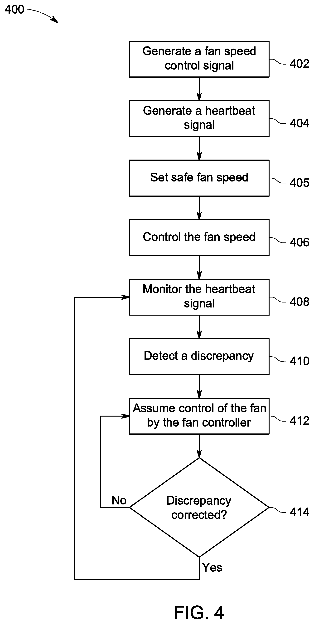
[0028] FIG. 4 illustrates a process for controlling a fan module for cooling a computer system, according to aspects of the present disclosure.
DETAILED DESCRIPTION
[0029] The various embodiments are described with reference to the attached figures, where like reference numerals are used throughout the figures to designate similar or equivalent elements. The figures are not drawn to scale, and they are provided merely to illustrate the instant invention. It should be understood that numerous specific details, relationships, and methods are set forth to provide a full understanding. One having ordinary skill in the relevant art, however, will readily recognize that the various embodiments can be practiced without one or more of the specific details, or with other methods. In other instances, well-known structures or operations are not shown in detail to avoid obscuring certain aspects of the various embodiments. The various embodiments are not limited by the illustrated ordering of acts or events, as some acts may occur in different orders and/or concurrently with other acts or events.
[0030] To that extent, elements and limitations that are disclosed, for example, in the Abstract, Summary, and Detailed Description sections, but not explicitly set forth in the claims, should not be incorporated into the claims, singly, or collectively, by implication, inference, or otherwise. For purposes of the present detailed description, unless specifically disclaimed, the singular includes the plural and vice versa. The word "including" means "including without limitation." Moreover, words of approximation, such as "about," "almost," "substantially," "approximately," and the like, can be used herein to mean "at," "near," or "nearly at," or "within 3-5% of," or "within acceptable manufacturing tolerances," or any logical combination thereof, for example.
[0031] The present disclosure describes devices and methods that include a heartbeat signal generated by a fan speed control circuit. The heartbeat signal is monitored by a fan controller within a fan module. When the fan controller detects that the heartbeat signal has stopped, or detects any other type of discrepancy indicating an abnormality, the fan controller takes over control of the fan speed. Specifically, the fan controller operates the fan at a safe fan speed to keep the system associated with the fan cool despite the abnormality.
[0032] FIG. 1 illustrates a schematic view of an electronic system 100 for controlling a fan module 102 with a heartbeat signal, according to aspects of the present disclosure. Although the present disclosure is primarily directed to computer systems, such as server systems, the electronic system 100 can be within any type of system that generates heat during use and that uses a fan to dissipate the heat. Moreover, the electronic system 100 of FIG. 1 can be for the entire system. For example, the electronic system 100 can be an overall server system, and the fan 108 (described below) can be for cooling the overall system. Alternatively, the electronic system 100 of FIG. 1 can be a component electronic system within a larger system. For example, the electronic system 100 can be a power unit, a graphics processing component, a central processing component, or the like within a computer system; and the fan 108 (described below) can be for cooling the specific component.
[0033] The electronic system 100 includes the fan module 102 and a fan speed control circuit 104. The fan module 102 includes a fan controller 106 and a fan 108. The fan speed control circuit 104 is separate from the fan module 102. In the context of computer systems, the fan speed control circuit 104 can be located on the motherboard. The fan speed control circuit 104 has access to and monitors one or more parameters of the electronic system 100. The parameters relate to the heat that is generated within the electronic system 100. From the parameters, the fan speed control circuit 104 determines the amount of cooling needed for the system 100. Based on the amount of cooling needed, the fan speed control circuit 104 generates a fan speed control signal. In the context of a server system, the fan speed control circuit can be a BMC. The BMC monitors parameters of the server system that relate to how much heat is being generated, and translates that information into the generated fan speed control signal. For example, the parameters can be processor, memory, and/or internal chassis temperatures. The fan speed control circuit 104 can generate the fan speed control signal based on hardware, firmware, software, or a combination thereof. The fan speed control signal can be any type of digital or analog signal. In one or more embodiments, the fan speed control signal can be a pulse width modulation signal.
[0034] The fan speed control circuit 104 is communicatively connected to the fan controller 106 of the fan module 102 via a connection 110. The connection 110 can be one or more wired connections, one or more wireless connections, or one or more wired and wireless connections. The fan speed control circuit 104 communicates the fan speed control signal to the fan controller 106 via the connection 110. In response to the fan speed control signal, the fan controller 106 operates the fan 108 at the instructed speed.
[0035] In one or more embodiments, the fan controller 106 can generate a fan operation signal and communicate the fan operation signal back to the fan speed control circuit 104. The fan operation signal can verify that the fan 108 is operating as instructed by the fan speed control circuit 104. In one or more embodiments, the fan operation signal can be a tachometer signal that reports the number of revolutions of the fan. Based on the number of revolutions, the fan speed control circuit 104 can verify that the fan 108 is operating at the appropriate speed or duty cycle.
[0036] According to the present disclosure, the fan speed control circuit 104 also generates a heartbeat signal and transmits the heartbeat signal to the fan controller 106. The heartbeat signal indicates normal operation of the fan speed control circuit. The fan controller 106 can then monitor for the heartbeat signal to determine whether there is any abnormality with the fan speed control circuit 104, or any other component of the electronic system 100 that may be affecting the fan speed control circuit 104. The heartbeat signal can be a continuous or periodic signal. In one or more embodiments, the heartbeat signal can be transmitted (embedded) within the fan speed control signal or can be transmitted as a separate signal. In one or more embodiments, the heartbeat signal can be transmitted over the same wired and/or wireless connection as the fan speed control signal and/or fan operation signal. Alternatively, the heartbeat signal can be transmitted over a different wired or wireless connection than the fan speed control signal and the tachometer signal.
[0037] For example, in one embodiment, the connection 110 can be a five-pin general purpose output pin connection. Two of the five pins can provide a common ground and a voltage supply (e.g., a nominal+12 Volts) to the fan module 102. The third pin can provide the fan speed control signal to the fan controller 106. The fourth pin can provide the fan operation signal from the fan controller 106 back to the fan speed control circuit 104. The fifth pin can be added to provide the heartbeat signal from the fan speed control circuit 104 to the fan controller 106.
[0038] However, in one or more embodiments, the connection 110 can vary from being a five-pin connection. For example, the connection 110 can be a four-pin connection, and the heartbeat signal can be provided via one of the other four pins. In one embodiment, the heartbeat signal can be a specific, periodic pulse-width modulation within the fan speed control signal that does not affect the speed of the fan; or negligibly affects the speed of the fan. For example, the specific, periodic pulse-width modulation can be a short positive (or negative) square wave immediately followed by a short negative (or positive) square wave that occurs according to a specific period. In which case, the two waves effectively negate each other with respect to changing the speed of the fan. However, the fan controller 106 can monitor for the specific, periodic pulse-width modulation within the fan speed control signal as the heartbeat signal. In such embodiments, a conventional connection between the fan speed control circuit 104 and the fan controller 106 can be used without having to add a fifth pin. However, other types of connections for the connection 110 are possible than those described above. Such other connections include, for example, a platform environment control interface (PECI) bus, an inter-integrated circuit (I.sup.2C) bus, and the like. In the case of the PECI bus and the I.sup.2C bus, the safe fan speed signal can be a command sent from the fan speed control circuit 104 to the fan controller 106.
[0039] The generation and transmittal of the heartbeat signal from the fan speed control circuit 104 to the fan controller 106 indicates that the electronic system 100 is operating normally with respect to control of the fan 108. Accordingly, the fan controller 106 within the fan module 102 monitors for a discrepancy in the heartbeat signal. A discrepancy can be the lack of the continuous heartbeat signal, the lack of the heartbeat signal during one period, or the lack of the heartbeat signal during two or more sequential or non-sequential periods.
[0040] When the fan controller 106 detects a discrepancy in the heartbeat signal, the fan controller 106 takes over control of the speed of the fan 108 from the fan speed control circuit 104. When the fan controller 106 takes over control of the fan 108, the fan controller 106 can operate the fan 108 at a safe fan speed. In one or more embodiments, the safe fan speed can be full speed to provide maximum cooling. In one or more embodiments, the safe fan speed can less than full speed. In one or more embodiments, the safe fan speed can be a default speed set within logic of the fan controller 106 that cannot be changed. Alternatively, in one or more embodiments, the safe fan speed can be set by the fan speed control circuit 104 any time before the discrepancy, such as at startup or reset of the fan speed control circuit 104 or the electronic system 100. The fan speed control circuit 104 can send the safe fan speed via the heartbeat signal, the fan speed control signal, or any other signal during operation. Thus, in the event of an issue with the fan speed control circuit 104 controlling the fan 108 through the fan controller 106, the heartbeat signal can prevent or reduce the likelihood of the electronic system 100 hanging or being damaged as a result of improper fan speed control. Instead, the fan controller 106 can assume control of the fan speed to maintain cooling within the system 100.
[0041] FIG. 2 illustrates a process 200 for controlling a fan within an electronic system, according to aspects of the present disclosure. The process 200 can be performed by the fan speed control circuit 104 and the fan controller 106 disclosed above (FIG. 1). The electronic system can be any electronic system, such as the electronic system 100, including a computer system, a sub-component within a computer system, or any other electronic system that uses a fan to dissipate generated heat. The process 200 begins at step 202, where a fan controller of a fan module monitors for a heartbeat signal. During normal operation, a fan speed control circuit that monitors parameters that correspond to the amount of heat generated by the electronic system generates the heartbeat signal. The heartbeat signal indicates normal operation of the electronic system. In one or more embodiments, normal operation of the electronic system includes the fan speed control circuit receiving the expected parameters used to generate a fan speed control signal. In one or more embodiments, normal operation also includes values of the parameters being within expected and/or predetermined ranges, such as normal operating conditions. Normal operation also includes the fan speed control circuit generating and outputting the fan speed control signal to the fan controller according to a predetermined scheme, such as continuously or periodically. The fan module can be associated with the cooling of any electronic system, such as a computer system or a component within a computer system. The heartbeat signal can be continuous or periodic. In one or more embodiments, the heartbeat signal can be a high/low toggling signal, a command/data signal, or a combination thereof.
[0042] At step 204, the fan controller of the fan module determines whether a discrepancy exists in the heartbeat signal. The discrepancy can be the lack of the fan speed control signal. For example, with a continuous fan speed control signal, the discrepancy can be the fan controller no longer receiving the signal. As another example, with a periodic fan speed control signal, the discrepancy can be the fan controller not receiving the signal for one period, or not receiving the signal for two or more sequential or non-sequential periods. As another example, for a toggling signal and/or a command data signal, the discrepancy can be an incorrect value within the signal. If a discrepancy does not exist, the process 200 loops back to step 202. If a discrepancy exists, the fan controller of the fan module detects a discrepancy in the heartbeat signal based on the monitoring, and the process 200 proceeds to step 206.
[0043] At step 206, in response to the fan controller detecting a discrepancy, the fan controller controls the fan according to a safe fan speed. The safe fan speed is configured to keep the fan operating at a speed that attempts to maintain the cooling of the electronic system, despite the lack of proper fan speed control by the fan speed control circuit. In one or more embodiments, the safe fan speed can be a maximum operating speed of the fan (i.e., full speed). In one or more embodiments, the safe fan speed can be less than the maximum operating speed but still a sufficient amount that, on average, should minimize the buildup of heat within the electronic system. For example, in one embodiment, the safe fan speed can be determined based on a worst case thermal simulation (e.g., CPU and memory running at full load), but still be less than full speed. In one embodiment, the safe fan speed can be pre-defined and fixed by thermal or system designer. The safe fan speed can be a default speed set within logic of the fan controller. Alternatively, the safe fan speed can be set by the fan speed control circuit prior to the discrepancy, as discussed further with respect to the process 300 below. For example, the safe fan speed can be the maximum speed which the fan speed control circuit sends to fan controller during normal system operation. The fan controller can record all fan speed requirements from the fan speed control circuit, and then update and keep the maximum speed as the safe fan speed.
[0044] In one or embodiments, the process 200 ends after step 206, and the fan controller controls the fan according to the safe fan speed indefinitely, or until power is cut from the fan module, the electronic system, or a combination thereof. In one or more embodiments, the process 200 optionally can proceed to step 208 where the fan controller determines whether the discrepancy in the heartbeat signal has been corrected. If the discrepancy has been corrected, the process 200 loops back to step 202, and the fan controller continues monitoring the heartbeat signal. If the discrepancy has not been corrected, the process 200 loops back to step 206, and the fan controller continues operating the fan according to the safe fan speed.
[0045] Based on the process 200, the heartbeat signal can prevent or reduce the likelihood of the electronic system hanging or being damaged as a result of improper fan speed control in the event of an issue with the fan speed control circuit. The fan controller can detect a discrepancy in the control of the fan speed via the heartbeat signal and take over control from the fan speed control circuit. The fan controller assuming control can reduce the likelihood of issues within the electronic system, in response to the buildup of heat.
[0046] In one or more embodiments, the fan controller can perform one or more additional or alternative functions in response to detecting a discrepancy in the heartbeat signal. The one or more functions aid in preventing the system from hanging, or being damaged, in response to the fan speed control circuit not being able to control the speed of the fan.
[0047] In one embodiment, the fan module can include an audible and/or electronic alarm that is triggered when the fan controller detects a discrepancy in the heartbeat signal. An alarm can alert an operator, technician, or the like, of the discrepancy. In response, the operator, technician, or the like can investigate the issue and take appropriate action, such as shutting the system down and/or manually controlling the fan speed using a switch or other manual control device within the fan module.
[0048] In one embodiment, the fan controller can be communicatively coupled to a circuit within the system that allows the fan controller to initiate shutdown of the system. The fan controller shutting the system down further prevents damage to the system caused by the inability to control the fan speed. In one embodiment, the fan controller can communicate to one or more CPUs within the system to reduce the clock speeds of the CPUs to reduce the amount of heat that is generated. In one embodiment, the fan controller can be communicatively coupled to a circuit within the system that allows the fan controller to signal or control the system or other key components (e.g., memory modules (e.g., dual in-line memory modules or DIMMs), a network interface controller (NIC), a storage module, or other components) to slow down or reduce heat.
[0049] FIG. 3 illustrates a process 300 for setting a safe fan speed within an electronic system, according to aspects of the present disclosure. The process begins at step 302, where the fan speed control circuit starts or resets, and begins generating and transmitting the fan speed control signal to the fan module. As described above, the fan speed control circuit monitors parameters of the electronic system associated with heat generation to generate the fan speed control signal. Step 302 can occur when the electronic system, such as the computer system, that includes the fan speed control circuit starts and/or resets.
[0050] At step 304, the fan speed control circuit sends the safe fan speed to the fan module. In one or more embodiments, the fan speed control circuit can send the safe fan speed to the fan module via a heartbeat signal, such as the heartbeat signal described in the process 200. In one or more embodiments, the fan speed control circuit can send the safe fan speed via another signal, such as the fan speed control signal. The fan speed control circuit can send the safe fan speed once at startup or after a reset, periodically or on demand, in response to a software, firmware, or hardware request. Thereafter, the fan module will have the safe fan speed stored in logic in the event of a discrepancy in the heartbeat signal. The process 300 can occur before the process 200 has initiated or simultaneously with the process 200, once the fan module and the fan speed control circuit startup.
[0051] FIG. 4 illustrates a process 400 for controlling a fan module for cooling a computer system, according to aspects of the present disclosure. The process 400 can be performed by the fan speed control circuit 104 and the fan controller 106 disclosed above (FIG. 1). The process 400 begins at step 402, when the fan speed control circuit of the computer system generates a fan speed control signal based on one or more parameters corresponding to heat generated within the computer system. As discussed above, the parameters can relate to, for example, one or more processor temperatures, one or more memory chip temperatures, one or more ambient temperatures within the computer system, or any other temperature associated with the computer system. The parameters can also relate to the amount of power consumed by the computer system, such as by the one or more processors, one or more memory chips, one or more power units, and the like.
[0052] At step 404, the fan speed control circuit generates a heartbeat signal. As discussed above, the heartbeat signal indicates normal operation of the fan speed control circuit.
[0053] In one embodiment, the process 400 can include step 405, where the fan speed control circuit generates a safe fan speed and transmits the safe fan speed to the fan controller, such as within the heartbeat signal. Alternatively, the fan speed control circuit can transmit the safe fan speed with the fan speed control signal or another signal. Further, although described in relation to step 404, the fan speed control circuit can generate and transmit the safe fan speed to the fan controller at any step or time prior to the step 410, such as when the fan speed control circuit starts or resets.
[0054] At step 406, the fan controller of the fan module controls the speed of the fan module based on the fan speed control signal generated and transmitted by the fan speed control circuit. The fan speed control circuit 104 can transmit the fan speed control signal to the fan controller via the connection 110, as described above. For example, the connection 110 can include a general purpose output pin, and the fan speed control circuit 104 can transmit the fan speed control signal via pulse-width modulation over the general purpose output in.
[0055] At step 408, the fan controller monitors the heartbeat signal generated and transmitted by the fan speed control circuit. The fan speed control circuit 104 can transmit the heartbeat signal to the fan controller via the connection 110, as described above. For example, the heartbeat signal can be transmitted over the same general purpose output pin as the fan speed control signal. In which case, the heartbeat signal can be embedded within the fan speed control signal. Alternatively, the fan speed control circuit can transmit the heartbeat signal over a separate general purpose output pin of the connection, or any other connection disclosed herein.
[0056] At step 410, the fan controller detects a discrepancy in the heartbeat signal based on the monitoring. The discrepancy can be the lack of the heartbeat signal, or any other variation in the heartbeat signal that indicates an abnormality (or potential abnormality) of the fan speed control circuit. For example, the discrepancy can be the lack of a periodic heartbeat signal for one period, or for more than two sequential or non-sequential periods. The discrepancy can be any other discrepancy disclosed above.
[0057] At step 412, the fan controller controls the speed of the fan based on a safe fan speed, in place of the fan speed control signal in response to the discrepancy. As disclosed above, the safe fan speed can be full speed for maximum cooling. Alternatively, the safe fan speed can be less than full speed. In one or more embodiments, the safe fan speed can be set in the logic of the fan controller; or can be set based on the fan controller having previously received the safe fan speed from the fan speed control circuit prior to the discrepancy.
[0058] At step 414, the fan controller can optionally determine whether the discrepancy in the heartbeat signal has been corrected. The fan controller can perform the determination continuously, periodically, or on demand, such as in response to a software, firmware, or hardware request. If the fan controller determines that the discrepancy in the heartbeat signal has been corrected, the process can loop back to step 408. If the fan controller determines that the discrepancy in the heartbeat signal has not been corrected, the process can loop back to step 412.
[0059] Based on the process 400, the computer system can control the fan module for cooling of the system. Further, in the event of an abnormality of the normal control, the lack of the heartbeat signal can prevent or reduce the likelihood of the computer system hanging or damaging one or more components as a result of improper fan speed and temperature control.
[0060] While various embodiments of the present invention have been described above, it should be understood that they have been presented by way of example only, and not limitation. Numerous changes to the disclosed embodiments can be made in accordance with the disclosure herein without departing from the spirit or scope. Thus, the breadth and scope of the present invention should not be limited by any of the above described embodiments. Rather, the scope of the invention should be defined in accordance with the following claims and their equivalents.
[0061] Although the invention has been illustrated and described with respect to one or more implementations, equivalent alterations and modifications will occur to others skilled in the art upon the reading and understanding of this specification and the annexed drawings. In addition, while a particular feature of the invention may have been disclosed with respect to only one of several implementations, such feature may be combined with one or more other features of the other implementations as may be desired and advantageous for any given or particular application.
[0062] The terminology used herein is for the purpose of describing particular embodiments only and is not intended to be limiting. As used herein, the singular forms "a", "an," and "the" are intended to include the plural forms as well, unless the context clearly indicates otherwise. Furthermore, to the extent that the terms "including", "includes", "having", "has", "with", or variants thereof are used in either the detailed description and/or the claims, such terms are intended to be inclusive in a manner similar to the term "comprising."
[0063] Unless otherwise defined, all terms (including technical and scientific terms) used herein have the same meaning as commonly understood by one of ordinary skill in the art to which this invention belongs. Furthermore, terms, such as those defined in commonly used dictionaries, should be interpreted as having a meaning that is consistent with their meaning in the context of the relevant art and will not be interpreted in an idealized or overly formal sense unless expressly so defined herein.
* * * * *
D00000
D00001
D00002
D00003
XML
uspto.report is an independent third-party trademark research tool that is not affiliated, endorsed, or sponsored by the United States Patent and Trademark Office (USPTO) or any other governmental organization. The information provided by uspto.report is based on publicly available data at the time of writing and is intended for informational purposes only.
While we strive to provide accurate and up-to-date information, we do not guarantee the accuracy, completeness, reliability, or suitability of the information displayed on this site. The use of this site is at your own risk. Any reliance you place on such information is therefore strictly at your own risk.
All official trademark data, including owner information, should be verified by visiting the official USPTO website at www.uspto.gov. This site is not intended to replace professional legal advice and should not be used as a substitute for consulting with a legal professional who is knowledgeable about trademark law.