Tubular Mast Assembly, Related Kit, And Methods
Daton-Lovett; Andrew ; et al.
U.S. patent application number 16/576171 was filed with the patent office on 2020-01-09 for tubular mast assembly, related kit, and methods. The applicant listed for this patent is RTL Materials Ltd.. Invention is credited to Andrew Daton-Lovett, Richard Wood.
| Application Number | 20200011083 16/576171 |
| Document ID | / |
| Family ID | 58688397 |
| Filed Date | 2020-01-09 |


View All Diagrams
| United States Patent Application | 20200011083 |
| Kind Code | A1 |
| Daton-Lovett; Andrew ; et al. | January 9, 2020 |
TUBULAR MAST ASSEMBLY, RELATED KIT, AND METHODS
Abstract
A connector element for a tubular mast assembly, a tubular mast assembly and a kit therefore, methods of assembling and disassembling, a guide device and a spreader are provided. In an aspect, a tubular mast assembly comprises first and second members each comprising a shell resiliently biased in the form of an elongate tube having longitudinal edges defining a slit along its length. A connector element comprising a first socket receives an end of the first member and a second socket receives an end of the second member so as to connect the first and second members into an extended tubular form. Each member can be disconnected from its socket and its shell opened out at the slit to assume a flattened form in which it can be wound into a coiled form for stowing the assembly.
| Inventors: | Daton-Lovett; Andrew; (Lymington, GB) ; Wood; Richard; (Lymington, GB) | ||||||||||
| Applicant: |
|
||||||||||
|---|---|---|---|---|---|---|---|---|---|---|---|
| Family ID: | 58688397 | ||||||||||
| Appl. No.: | 16/576171 | ||||||||||
| Filed: | September 19, 2019 |
Related U.S. Patent Documents
| Application Number | Filing Date | Patent Number | ||
|---|---|---|---|---|
| PCT/GB2018/050539 | Mar 2, 2018 | |||
| 16576171 | ||||
| Current U.S. Class: | 1/1 |
| Current CPC Class: | E04H 15/60 20130101; E04H 12/342 20130101; E04H 12/02 20130101; E04H 12/2238 20130101 |
| International Class: | E04H 12/34 20060101 E04H012/34; E04H 12/22 20060101 E04H012/22; E04H 15/60 20060101 E04H015/60 |
Foreign Application Data
| Date | Code | Application Number |
|---|---|---|
| Mar 20, 2017 | GB | 1704370.4 |
Claims
1. A tubular mast assembly comprising: first and second members each comprising a shell resiliently biased in a form of an elongate tube having longitudinal edges defining a slit along its length; and, a connector element comprising a first socket which receives an end of the first member and a second socket which receives an end of the second member so as to connect the first and second members into an extended tubular form, wherein each member can be disconnected from its socket and is constructed and arranged such that the shell can be opened out at the slit to assume a flattened form in which it can be wound about an axis extending transversely to its longitudinal direction to assume a coiled form for stowing the tubular mast assembly.
2. The tubular mast assembly of claim 1, wherein each member exhibits bi-stability in its coiled and extended forms.
3. The tubular mast assembly of claim 1, comprising a second connector element comprising a first socket and a second socket, wherein the first socket of the second connector element receives an end of the first member that is opposed to the end of the first member that is received in the first connector element, and wherein the second socket of the second connector element is adapted to provide a first foot element at an end of the second connector element for supporting the tubular mast assembly on an object or on the ground.
4. The tubular mast assembly of claim 3, wherein the second socket of the first connector element further has a second foot element, such that the first connector element and second connector element are interchangeable in the tubular mast assembly in that they are both able to provide a foot element to support the tubular mast assembly and both able to connect the first and second members.
5. The tubular mast assembly of claim 4, wherein the first sockets of the first and second connector elements further provide respective third foot elements.
6. The tubular mast assembly of claim 3, wherein the first foot element comprises a ring shape, castellated surface surrounding the second socket for gripping an object or surface.
7. The tubular mast assembly of claim 3, wherein the first foot element comprises a rubber or high friction material surrounding the second socket for gripping an object or surface and/or for gripping a member inserted in the second socket.
8. The tubular mast assembly of claim 1, wherein at least one member is biased in the form of a tube having an external diameter larger than an internal diameter of the corresponding socket in which it is received, wherein when received in the corresponding socket, the tube is compressed against the bias of the tube to fit in the socket.
9. The tubular mast assembly of claim 1, wherein the connector element has projecting features inside each socket for guiding at least one edge portion of its member when it is inserted into the corresponding socket, and/or for interacting with the edge portion when fully inserted into the corresponding socket to help retain its member in place.
10. The tubular mast assembly of claim 1, wherein the connector element comprising a tubular sleeve and at least one stop element fixed within the tubular sleeve, wherein one or both sockets are defined by an open end of the tubular sleeve and the stop element such that a leading edge of the corresponding member when fully inserted into the or each socket abuts the at least one stop element.
11. The tubular mast assembly of claim 10, wherein the tubular sleeve is corrugated in profile, wherein the stop element is engaged with corrugations in the tubular sleeve.
12. The tubular mast assembly of claim 10, wherein the stop element is fixed by at least one fastener that passes through a hole in the tubular sleeve and clips to the stop element.
13. The tubular mast assembly of claim 10, wherein the tubular sleeve comprises a plastics material, and at least one member has a foot element comprising plastics material, wherein the foot element is adhered or welded to the tubular sleeve.
14. The tubular mast assembly of claim 1, wherein the tubular mast assembly comprises three or more members joined by connector elements.
15. The tubular mast assembly of claim 1, comprising a support element fixed to a free end of one of the members that is not inserted into one of sockets of a connector element, the support element being adapted to support a load.
16. The tubular mast assembly of claim 15, wherein the support element comprises a third socket for receiving the free end of one of the members.
17. The tubular mast assembly of claim 15, wherein the support element comprises fixtures for attaching tethers to tether the tubular mast assembly in a deployed position.
18. The tubular mast assembly of claim 15, comprising a flexible sheet or netting supported by the tubular mast assembly, wherein the support element is a spreader element comprising a surface having an increased cross sectional area relative to the members and gripping elements or surface treatment for gripping the flexible sheet or netting.
19. The tubular mast assembly of claim 18, wherein the gripping elements comprise a plurality of blunt cylindrical studs extending from the surface of the spreader element.
20. The tubular mast assembly of claim 1, wherein the members are reversibly received in the sockets permitting disassembly of the tubular mast assembly by withdrawing the members from the sockets.
21. A tubular mast assembly in a kit form, the kit comprising: first and second members each comprising a shell in a coiled form in which the shell has a flattened form and is wound about an axis, wherein each shell is configurable between its coiled form and an extended form in which it is resiliently biased in a form of an elongate tube extending transversely to the axis having longitudinal edges defining a slit along its length; and, a connector element comprising a first socket for receiving an end of the first member and a second socket for receiving an end of the second member, so as to connect the first and second members into the tubular mast assembly.
22. The tubular mast assembly in the kit form of claim 21, further comprising a guide device, the guide device comprising: a base; a concave portion conforming generally to a curved surface of a coiled portion of the first or second member, wherein the concave portion has a low friction surface such that with the first or second member being in a partially extended state, having a coiled portion and an extended portion, with the coiled portion received in the concave portion of the guide device, a force applied on the extended portion towards the concave portion causes the coiled portion to rotate against the low friction surface thereby progressively adding the extended portion to the coiled portion.
23. The tubular mast assembly in the kit form of claim 21, comprising a container in which the kit form is stowed, wherein at least one part of the kit form at least partly occupies a space defined inside an interior coil of at least one member.
24. A connector element, comprising: a body comprising first and second sockets constructed and arranged to receive tubular elements so as to connect together the tubular elements into the tubular mast assembly, wherein at least the first socket is additionally constructed and arranged as a foot element adapted to interface to the ground or another object on which the tubular mast assembly is to be supported, such that where the second socket receives a tubular element and the first socket does not, the foot element is accessible at an end of the tubular mast assembly to provide support to the tubular mast assembly, such that where a plurality of connector elements are supplied in a kit, the connector elements is selectively used to connect together tubular elements and to act as the foot element.
25. A connector element according to claim 24, wherein the foot element comprises one or more of: a ring shape encircling the first socket; projections or an uneven surface arranged to provide increased traction on the ground or the another object; a fastener for attaching the foot element to an object or surface; and a rubberized or high grip surface for providing traction on the ground or another object, wherein the rubberized or high grip surface optionally extends to an inner surface of the first socket to help secure a tubular element inserted into the first socket.
26. A spreader for supporting a flexible sheet or net, comprising: a socket for receiving an end of a tubular member; the spreader having a greater surface area than that of the end of the tubular member; and, a plurality of blunt, cylindrical studs on a surface of the spreader.
27. A guide device, comprising: a base; a concave portion conforming to a curved surface of a coiled portion of the first or second member, wherein the concave portion has a low friction surface such that with the first or second member being in a partially extended state, having the coiled portion and an extended portion, with the coiled portion received in the concave portion of the guide device, a force applied on the extended portion towards the concave portion causes the coiled portion to rotate against the low friction surface thereby progressively adding the extended portion to the coiled portion.
Description
CROSS REFERENCE TO RELATED APPLICATIONS
[0001] This application is a continuation-in-part filing under 35 U.S.C. .sctn. 111(a) of International Patent Application No. PCT/GB2018/050539, filed Mar. 2, 2018, which claims the benefit of British Patent Application No. 1704370.4, filed Mar. 20, 2017, each of which is incorporated herein by reference in its entirety.
TECHNICAL FIELD
[0002] The present invention relates to a tubular mast assembly, a kit for a tubular mast assembly, methods of assembling a kit to form a tubular mast assembly and disassembling a tubular mast assembly, to a connector element, to a guide device and to a spreader.
BACKGROUND
[0003] It is known in general in various applications to employ modular, multi-piece pole systems for supporting objects, flexible sheets and netting and the like. Typically these might comprise aluminum tubular pole elements where one end of a pole is adapted as a socket to receive the end of another pole, allowing the poles to be fastened together to create a longer pole. For instance, in some systems, two pole elements of approx. 1.3 m (4 feet) length may connect together to form an approx. 2.6 m (8 feet) pole for supporting a canvas or other structure. FIG. 1 for example shows plural poles 1 formed from two pole structures 2a,2b joined together 3 to support camouflage netting 4 which is tethered to the ground 5. While these systems can perform adequately for some applications, they generally tend to be overly heavy, bulky, unwieldy and difficult to stow and deploy, as well as suffering from undesirable material properties.
SUMMARY
[0004] The present invention aims to mitigate some or all of these problem in known systems.
[0005] According to an aspect of the present invention, there is provided a tubular mast assembly comprising:
[0006] first and second members each comprising a shell resiliently biased in the form of an elongate tube having longitudinal edges defining a slit along its length; and,
[0007] a connector element comprising a first socket which receives an end of the first member and a second socket which receives an end of the second member so as to connect the first and second members into an extended tubular form,
[0008] wherein each member can be disconnected from its socket and is constructed and arranged such that the shell can be opened out at the slit to assume a flattened form in which it can be wound about an axis extending transversely to its longitudinal direction to assume a coiled form for stowing the assembly.
[0009] Thus a mast assembly can be formed from individual slit tubular elements joined end to end in a structurally rigid form using one or more connector elements. The mast assembly can be made to different lengths and combined with other mast assemblies to support flexible sheet materials such as netting, or other objects, or in principle any application where a rigid elongate structure is required. Thus, "mast" as used herein encompasses any boom, beam, lever, rigid elongate member for supporting or positioning an object, material, load, etc., or for actuation or anywhere where an elongate structurally rigid member is required. The slit tubular elements can be coiled when disassembled from the connector elements for compact storage. Thus, a convenient and flexible modular mast system is provided.
[0010] The tubular elements may be formed from a shell of plural fiber reinforced layers in a laminate resiliently biased in a slit tube form, but allowing the tube to be opened at the slit to a flat profile for coiling. Preferably the shells allow progressive coiling from one end and are reversibly configurable between coiled and extended states.
[0011] In an embodiment, the or each member exhibits bi-stability in its coiled and extended forms. Thus, the members may be coiled for storage without needing external constraint to keep them in the coiled form.
[0012] In an embodiment, the assembly comprises a second connector element comprising a first socket and a second socket, wherein the first socket of the second connector element receives an end of the first member that is opposed to the end of the first member that is received in the first connector element, and wherein the second socket of the second connector element is adapted to provide a foot element at the end of that connector element for supporting the assembly on an object or on the ground. Thus, connector element has a dual function in being able to connect two members together or to connect to one, end member to act as a foot for adapting the mast assembly to suitably interface with the ground or whatever surface or object the mast assembly is to be deployed on. This simplifies the elements that go into the mast assembly, leading to simpler manufacturing and assembly/disassembly.
[0013] In an embodiment, the second socket of the first connector element also has a foot element, such that the first connector element and second connector element are interchangeable in the assembly in that they are both able to provide a foot element to support the assembly and both able to connect the first and second members. Thus, the connector elements may be substantially identical and both have dual functionality.
[0014] In an embodiment, the first sockets of the first and second connector elements also provide respective foot elements. Thus, the connector elements are effectively reversible, such that both ends provide both functions, which again leads to simpler manufacture and assembly/disassembly.
[0015] In an embodiment, the foot element comprises a ring shape, castellated surface surrounding the second socket for gripping an object or surface. Thus, the castellations, i.e. an uneven surface with raised or projecting features, improves the ability of the foot to grip the object or terrain on which the mast assembly is to be deployed.
[0016] In an embodiment, the foot element comprises a rubber or high friction material surrounding the second socket for gripping an object or surface and/or for gripping a member inserted in the second socket.
[0017] In an embodiment, at least one member is biased in the form of a tube having an external diameter larger than the internal diameter of the socket in which it is received, wherein when received in the socket, the tube is compressed against the bias of the tube to fit in the socket. Thus, the tubular member fits tightly in the socket, helping prevent the tube from pulling out or shifting in the socket.
[0018] The longitudinal edges of the slit tube subtend angle of preferably at least 300 degrees and preferably less than 450 degrees. In embodiments the longitudinal edges of the slit tube subtend angle of slightly less than 360 degrees (e.g. between 300 and 358 degrees, or more preferably between 340 and 358 degrees) to leave a relatively small gap to aid compression. In other examples, the member may subtend an angle of over 360 degrees to overlap the edges (e.g. between 362 and 450 degrees). Nonetheless, the slit tube may have edges that meet, in which case the user might displace one edge relative to the other edge so that one passes the other when the tube is compressed to insert it into a socket.
[0019] Optionally, in an embodiment, the connector element may have projecting features inside the socket for guiding at least one edge portion of its member when it is inserted into the socket and/or for interacting with the edge portion when fully inserted into the socket to help retain the member in place. For instance, the connector element may have an internally tapering surface to guide the edges of the member as they are inserted to the desired fully inserted position. Optionally, the features may also interact with the longitudinal edges of the slit to help hold the tubular member in position in the socket.
[0020] In an embodiment, the connector element comprises a tubular sleeve and at least one stop element fixed within the sleeve, wherein one or both sockets are defined by an open end of the sleeve and the stop element such that the leading edge of the member when fully inserted into the or each socket abuts the at least one stop element. The sleeve may be corrugated in profile. This improves the bending strength of the member compared with a cylindrical sleeve. The stop element keys with the corrugations in the sleeve. For instance, the stop element has projecting elements that extend into grooves of corrugation and help keep the stop element in place.
[0021] In an embodiment, the stop element is fixed by at least one fastener that passes through a hole in the sleeve and clips to the stop element.
[0022] In an embodiment, the sleeve comprises a plastics material, and at least one member has a foot comprising plastics material adhered or welded to the sleeve. The rubberized surface may then be over molded to the plastics material in the foot.
[0023] In an embodiment, the assembly comprises three, or four, or five, or more members joined by connector elements.
[0024] In an embodiment, the assembly comprises a support element fixed to a free end of one of the members that is not inserted into a socket of a connector element, the support element being adapted to support a load. For instance, the support element may grip, or attach etc. or spread forces and transmit forces to members in suitable way that does not damage the material. In an embodiment, the support element comprises a socket for receiving the free end of the member. Thus, the support element may attach to the tubular members in a similar way to the way the connector element attaches to the tubular members. The support element may further comprise fixtures for attaching tethers to tether the assembly in a deployed position.
[0025] In an embodiment, the assembly may comprise a flexible sheet or netting supported by the assembly, wherein the support element is a spreader element comprising a surface having an increased cross sectional area relative to the members and gripping elements or surface treatment for gripping the flexible sheet or netting. The flexible sheet or netting may comprise a tent, canopy, waterproof covering, antiradar or heat signature, or camouflage netting or the like.
[0026] In an embodiment, the gripping elements comprise a plurality of blunt cylindrical studs extending from the surface of the spreader.
[0027] In an embodiment, the members are reversibly received in the sockets permitting disassembly of the assembly by withdrawing the members from the sockets. Preferably the members are held in the sockets by a friction fit or the like, can be simply pulled out of the socket manually without requiring tools.
[0028] In an embodiment, the connector element is sized to fit at least partially in the space in the inner coil of a member. In an embodiment, at least one coiled member is adapted to fit within the coil of another member.
[0029] In embodiments, the tubular members, connector elements and support elements may comprise substantially only plastics and rubber materials and preferably at least no metal parts so as to be radar invisible and safe from lightning strikes.
[0030] According to a second aspect of the present invention, there is provided a kit for a tubular mast assembly, the kit comprising:
[0031] first and second members each comprising a shell in a coiled form in which the shell has a flattened form and is wound about an axis, wherein each shell is configurable between its coiled form and an extended form in which it is resiliently biased in the form of an elongate tube extending transversely to the axis having longitudinal edges defining a slit along its length; and,
[0032] a connector element comprising a first socket for receiving an end of the first member and a second socket for receiving an end of the second member so as to connect the first and second members into a tubular mast assembly.
[0033] Thus, the assembly in kit form is compact and light for storage and transportation, whilst being able to form a versatile mast assembly, as described above. Different length members may be provided, e.g. two lengths, allowing a large variety of different assembled lengths to be achieved. For instance, small members connected to large members can provide a number of equal, medium length masts, whilst small members connected together and large members connected together provides shorter and longer masts allowing different mast lengths to be provided which may be useful in some applications, e.g. for supporting different shapes of netting or canopies to be supported, according to need. Slit tubular members of different lengths may nonetheless have generally similar sizes to each other when coiled, meaning that compact and efficient packing of the kit is still possible.
[0034] The kit may comprise a container in which the kit is stowed, wherein at least one part of the kit at least partly occupies the space defined inside the interior coil of at least one member. Thus, for instance, a connector element may be disposed in the inner space of one or more coiled members. Alternatively or additionally, a coiled member may be disposed in the inner space of one or more other coiled members. The diameters of the various elements may naturally be non overlapping, i.e. the outer diameter of one element is smaller than the inner diameter of the coil in which it is to be stowed, such that the element can simply be inserted. Alternatively, the inner element may act as a bobbin on which the outer coil can be wound, so hold the outer open to the necessary extent. This allows very dense, compact packing of the elements of the kit which is a significant advantage to the arrangement of the mast assembly kit as separate connector elements and coiled members.
[0035] According to a third aspect of the present invention, there is provided a method of assembling a kit to form a tubular mast assembly, the method comprising:
[0036] uncoiling first and second members, each member comprising a shell in a coiled form in which the shell has a flattened form and is wound about an axis, wherein each shell is uncoiled into an extended form in which it is resiliently biased in the form of an elongate tube extending transversely to the axis having longitudinal edges defining a slit along its length;
[0037] inserting an end of the first member into a first socket of a connector element; and,
[0038] inserting an end of the second member into a second socket of a connector element so as to connect the first and second members into a tubular mast assembly.
[0039] The method may comprise connecting a second connector element in the kit comprising a first socket and a second socket, wherein an end of the first member that is opposed to the end of the first member that is received in the first connector element is inserted into the first socket of the second connector element, and wherein the second socket of the second connector element is adapted to provide a foot element at the end of that connector element for supporting the assembly on an object or on the ground.
[0040] The method may comprise connecting third or more members with additional connector elements.
[0041] The method may comprise connecting a support element fixed to a free end of one of the members that is not inserted into a socket of a connector element, the support element being adapted to support a load.
[0042] The method may comprise compressing an end of the member to reduce its diameter before inserting it into a socket, and releasing the member such that the diameter expands due to its resilient bias to provide a friction fit in the socket. This provides a simple, but secure way of connecting a tubular member into a socket which can be accomplished manually without additional tools.
[0043] The method may comprise supporting a load with the tubular mast assembly. The load supported may be a netting or fabric or any flexible material sheet, e.g. woven, knitted or braided, or an object such as a camera, light, transmitter and/or receiver for receiving signals. A support element may be provided at the distal end of the mast adapted to support the load by way of fasteners, clamps, etc.
[0044] The method may comprise disassembling the assembly, coiling the members and stowing the kit.
[0045] The method may comprise stowing at least one component of the kit within the inner coil of a coiled member.
[0046] Accordingly to a fourth aspect of the present invention, there is provided a method of disassembling a tubular mast assembly comprising:
[0047] first and second members each comprising a shell resiliently biased in the form of an elongate tube having longitudinal edges defining a slit along its length; and,
[0048] a connector element comprising a first socket which receives an end of the first member and a second socket which receives an end of the second member so as to connect the first and second members into an extended tubular form, the method comprising disconnecting each member from its socket, opening the shell of each member out at the slit to assume a flattened form in which it is wound about an axis extending transversely to its longitudinal direction to assume a coiled form for stowing the assembly.
[0049] According to a fifth aspect of the present invention, there is provided a connector element for a mast assembly kit, the connector element comprising:
[0050] a body comprising first and second sockets constructed and arranged to receiving tubular elements so as to connect together the tubular elements into a mast assembly, wherein at least the first socket is additionally constructed and arranged as a foot element adapted to interface to the ground or another object on which the mast assembly is to be supported, such that where the second socket receives a tubular element and the first socket does not, the foot element is accessible at the end of the mast assembly to provide support to the mast assembly, such that where plural connector elements are supplied in a kit, the connector elements can interchangeably be used to connect together tubular elements and to act as a foot element.
[0051] In an embodiment, the foot element comprises one or more of:
[0052] a ring shape encircling the first socket;
[0053] projections or an uneven surface arranged to provide increased traction on the ground or other object;
[0054] a fastener for attaching the element to an object or surface; and
[0055] a rubberized or high grip surface for providing traction on the ground or another object, wherein the rubberized or high grip surface optionally extends to an inner surface of the first socket to help secure a tubular element inserted into that socket.
[0056] According to a sixth aspect of the present invention, there is provided a spreader for supporting a flexible sheet or net, comprising:
[0057] a socket for receiving an end of a tubular member;
[0058] a spreader top surface having a greater surface area that that of the end of the tubular member; and,
[0059] a plurality of blunt, cylindrical studs on the surface of the spreader.
[0060] This allows materials and netting so be safely supported by a mast formed from the spreader and tube by the increased surface area of the spreader where the relatively blunt studs prevent the netting or material from shifting after being thrown over the spreader, and preventing damage to the material or netting or coatings or other additives applied to the material or netting, whilst allowing the material or netting to be simply removed when disassembling the mast. Comparative technology in the prior art relies on dense, pointed, "bristle-like" projections to snag the fabric and retain it, at the cost of potentially causing damage to the material and coatings that may be applied to it.
[0061] According to a seventh aspect of the present invention, there is provided a guide device, the guide device comprising: a base; a concave portion conforming generally to the curved surface of a coiled portion of the first or second member, wherein the concave portion has a low friction surface such that with the first or second member being in a partially extended state, having a coiled portion and an extended portion, with the coiled portion received in the concave portion of the guide device, a force applied on the extended portion towards the concave portion causes the coiled portion to rotate against the low friction surface thereby progressively adding the extended portion to the coil. The invention also extends to a method of coiling an extendible member by placing the coiled portion of a partially coiled member in the concave portion and applying a force towards the concave portion to cause the member to coil. The guide device is suitable for use with the tubular mast assembly kit described above, and may speed the process of disassembling the assembly for packing away. However, the guide device is suitable for use with any slit tubular member that is to be coiled.
[0062] The invention also extends to support elements having a socket for receiving an end of an extendible member and at least one of a clamp for a light fixture, a hook or other attachment means for attaching to an object.
[0063] It will be appreciated that any features expressed herein as being provided "in one example" or "in an embodiment" or as being "preferable" may be provided in combination with any one or more other such features together with any one or more of the aspects of the present invention. In particular, the extendible member, joining techniques and join testing system described in relation to one aspect may generally be applicable to the others.
BRIEF DESCRIPTION OF THE DRAWINGS
[0064] Embodiments of the present invention will now be described by way of example with reference to the accompanying drawings, in which:
[0065] FIG. 1 shows an example of a prior art system for supporting camouflage netting;
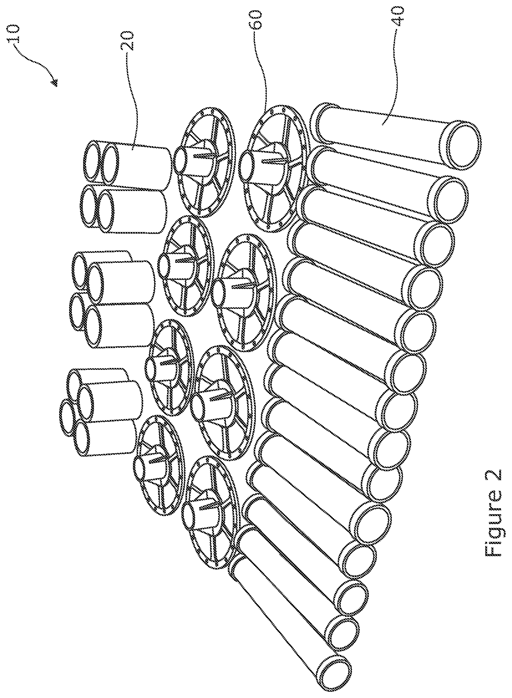
[0066] FIG. 2 shows an example of a kit for a tubular mast assembly according to an embodiment of the present invention;
[0067] FIG. 3 shows an example of a tubular mast assembly according to an embodiment of the present invention in which elements of the kit shown in FIG. 2 have been assembled;
[0068] FIG. 4 shows an extendible member which may form part of the kit of FIG. 2;
[0069] FIG. 5 shows a connector element which may form part of the kit of FIG. 2;
[0070] FIG. 6 shows a cross sectional view of the connector element of FIG. 5;
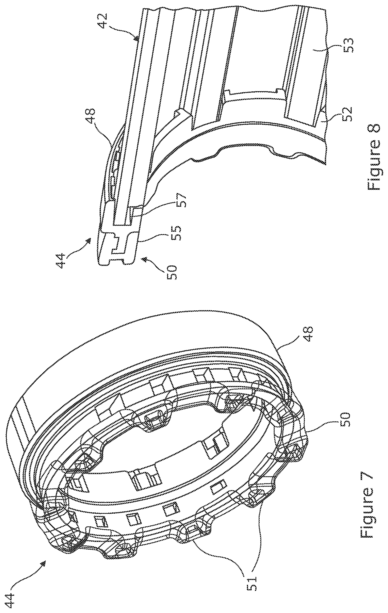
[0071] FIG. 7 shows a detail view of an example of a foot element which may form part of the connector element of FIG. 5;
[0072] FIG. 8 shows a cross sectional view of the foot element of FIG. 7 attached to the rest of connector element;
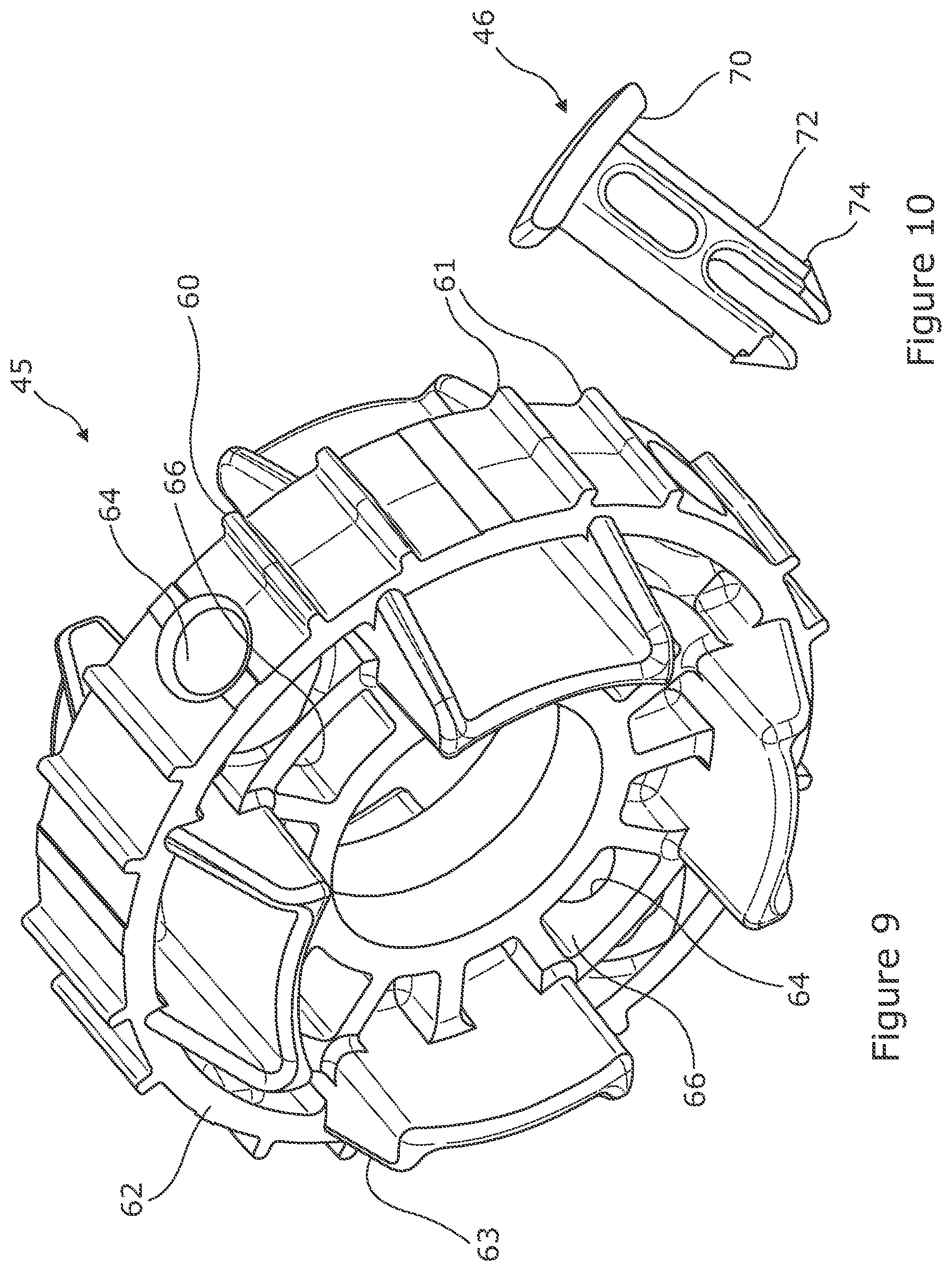
[0073] FIG. 9 shows an example of a stop element which may form part of the connector element of FIG. 5;
[0074] FIG. 10 shows an example of a fastener for connecting the stop element of FIG. 9 with the rest of the connector element;
[0075] FIG. 11 shows an example of a supporting member according to an embodiment of the present invention, which may form a part of the kit of FIG. 2;
[0076] FIGS. 12a and 12b show the kit of FIG. 2 packing into a storage container; and
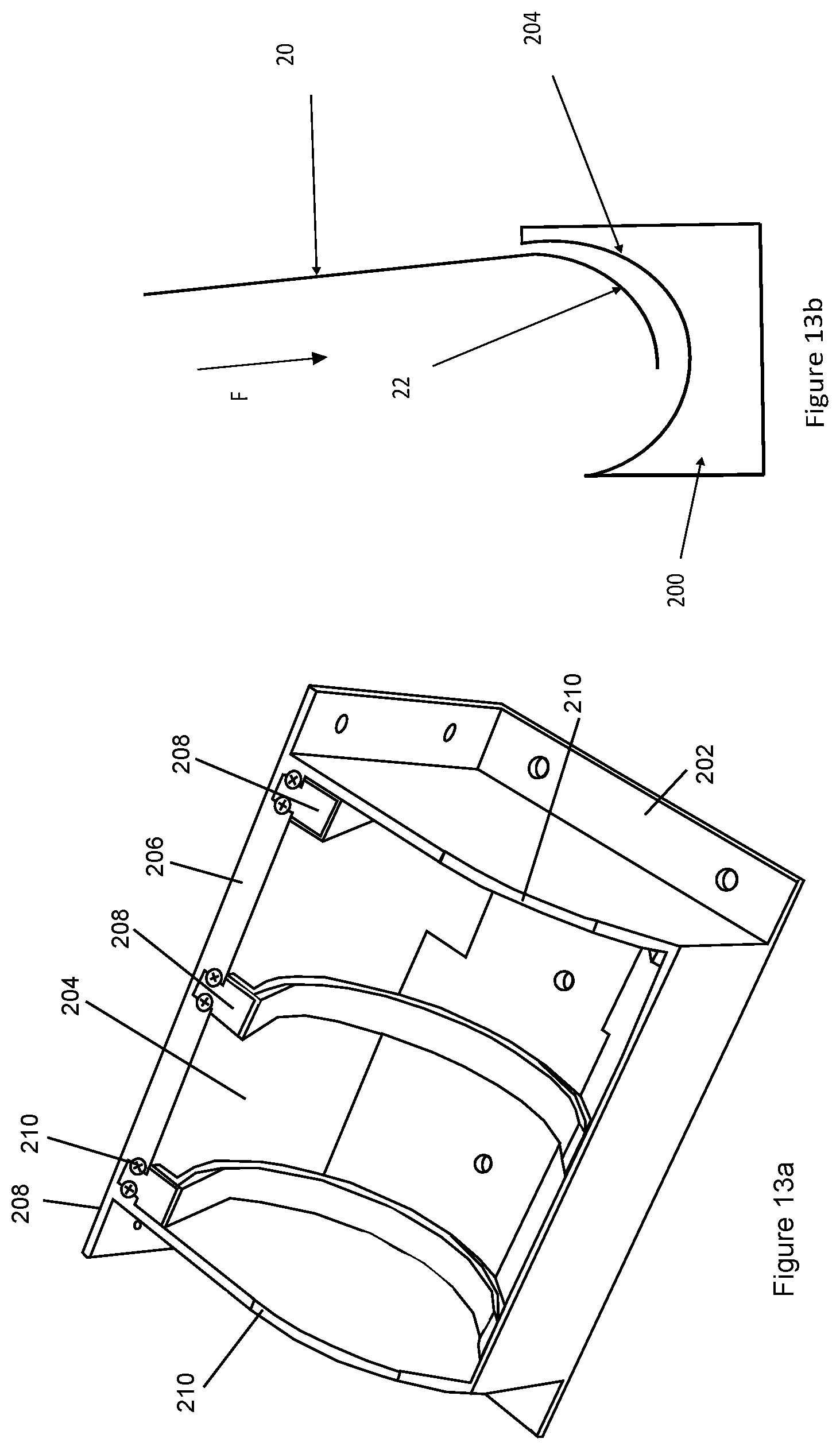
[0077] FIG. 13a shows a projection view of an example of coiling guide device according to an embodiment of the present invention; and
[0078] FIG. 13b shows in cross section an extendible member being coiled by the coiling guide device of FIG. 13a.
DETAILED DESCRIPTION
[0079] FIG. 2 shows an example of a kit 10 for a modular tubular mast assembly according to an embodiment of the present invention. The kit 10 comprises plural elements including plural extendible members 20, plural connector elements 40 and plural support elements, in particular, spreader elements 80 in this example, for supporting netting or other flexible sheet material or fabric.
[0080] FIG. 3 shows an example of a modular tubular mast assembly 11 constructed from elements of the kit 10 shown in FIG. 2. As will be described in more detail in the following, the extendible members 20 can be extended from a coiled configuration as shown in FIG. 2 to an extended, slit tubular configuration. In this extended configuration, a first member 20a is joined to a second member 20b by a first connector element 40a. A second connector element 40b is connected to the bottom end of the second member 20b and acts as a foot for the assembly, supporting the assembly on the ground 12 or some other object. The first end of the first member 20a is connected to a spreader element 80, which is used to support netting 13. Plural such tubular mast assemblies 11 can be constructed from the kit 10 and used to support the netting 13. Guy ropes or other tethers 14 may be attached to the spreader 80 or connector elements 40 or some other convenient point on the assembly 11 to stabilize the tubular support assembly 11. The kit 10 may comprise members 20 of more than one length when extended. In principle, the kit 10 may comprise members 20 having more than one diameter when extended, with connector elements 40 and spreaders 80 adapted to fit each diameter.
[0081] FIG. 4 shows an example of an extendible tubular member 20 comprising a fiber reinforced shell 21. The member 20 can be reconfigured between a coiled state 22 and an extended state 23, via a transition stage 24. In the extended state 23 the member 20 is generally elongated and biased to have a curved or non-linear cross section in a direction transverse to the longitudinal axis 25 of the member. (References to longitudinal axis or longitudinal extent or direction of extension or retraction in this document generally refer to this axis 25). Thus, the longitudinal edges 26 form a slit 27 in the generally curved, tubular form. This curvature can be adapted and thus the cross section of the extended portion can comprise anything from a closed or substantially closed circular shape, or other generally closed shapes. The member 20 is resiliently biased in this curved cross section when extended. This gives structural rigidity to the member 20 when extended. In the coiled state 22 the member 20 is generally opened out at the side longitudinal edges 26 to have a flat cross section, and is coiled around an axis 29 that is generally transverse to the longitudinal axis 25 of the member 20.
[0082] The shell 21 is generally thin to aid coiling, e.g. typically between 0.5 mm and 5 mm for most applications. Such members are sometimes referred to as STEMs (Slit Tubular Extendable Members).
[0083] Typical lengths of the extended members 20 may be between 1 m and 5 m and typical diameters may be between 5 cm and 15 cm. It will be appreciated that in principle almost any length and diameter can be used according to the application.
[0084] In the present example, the shell 21 may be formed from a thermoplastic matrix with fiber reinforcements, such as a fiber reinforced polymer ("FRP" hereafter). The fibers may be glass, carbon, or aramid, while the polymer may be polypropylene, polyethylene, a polyamide, polyester thermoplastic, poly-ether-ether-ketone or any other polymer suited to the particular requirements of the task at hand. The composite material may comprise a single layer or plural layers with fibers oriented in different directions in each lamina. The use of fibrous materials mechanically enhances the strength and elasticity of the plastic matrix. The extent that strength and elasticity are enhanced in a fiber reinforced plastic depends on the mechanical properties of both the fiber and the matrix, their volume relative to one another, and the fiber length and orientation within the matrix. FRPs are widely used in many areas such as aerospace and automotive industries, and are not described in detail herein.
[0085] In the present example, the member 20 is a bistable reelable composite (BRC). Such a bistable member has a first stable state in the coiled form 22, where the cross section of the member 20 is generally flat and a second stable state in the extended form 23, where the cross section of the member is curved as previously described. The bistable member 20 may be capable of reversible configuration between its coiled and extended forms a plurality of times. Suitable structures are disclosed in the following international patent applications, each of which is incorporated here by reference: WO88/08620A1, WO97/35706A1, WO99/62811A1, WO99/62812A1 and WO2012/168741A1. Such bistable structures are available from RolaTube Technology Limited of Lymington, the United Kingdom.
[0086] In general, there are two ways to make a tube bistable: either by altering the bending stiffness of the structure so that it is no longer isotropic, for instance by using a fiber-reinforced composite, or by setting up an initial prestress in the structure. The BRC in the present example uses the first technique. This involves arranging the fibers to increase the torsional stiffness, and increase the coupling between bending in the longitudinal and transverse directions.
[0087] Normally when something is bent the amount of energy stored by that bending (the total strain energy) rises as the degree of bending increases. In BRCs, once the initial curvature is straightened as the tube is opened, the stiffness along the longitudinal axis drops and the forces acting on the material of the tube arising by the deformed surface layer fibers can act to flip it into the coiled form. As this second curvature forms, the total strain energy drops, thereby forming a second stable form, or more stable form, for this section.
[0088] These principles operate in reverse when moving from the coiled state to the extended state.
[0089] Thus, structural members are formed that exhibit a stable geometry in both the extended and coiled states. These manage the problems of difficult handling and complicated mechanisms by forming STEM type structures from materials that have been engineered so as to make them easy to coil and handle.
[0090] FIG. 5 shows a projection view and FIG. 6 shows a cross sectional view of a connector element 40 comprising a corrugated sleeve 42 with a foot piece 44 at each end. Fasteners 46 extend through holes 47 in the wall of the sleeve 42 to fasten a stop element 48 inside the sleeve 42 generally midway along the length of the sleeve 42. The sleeve 42, stop element 48 and fastener preferably are made from plastics material. The connector element 40 has a socket 41 at each end projecting through the foot piece 44 and into the sleeve 42. Each socket 41 is constructed arranged to receive a member 20, which can be inserted until it abuts the stop element 48. The sockets 41 are preferably relatively deep to support the tubular members 20 and resist bending loading on the mast assembly 11. For example, the sockets 41 may be at least as deep as their width and in some examples will be at least twice as deep as their width or more. The corrugated design give considerably larger bending strength to the connector element, thereby allowing the wall thickness of the connector piece to be reduced and the product to be lighter.
[0091] The inside diameter of the socket 41 is preferably slightly less than the unconstrained diameter of the extended tube, for instance, the tube diameter may be 0.5% to 5% greater than the socket diameter. Thus, to insert the member 20 into the socket, the member 20 is first uncoiled to its slit tubular form and then the end of the member is compressed by the user to reduce its diameter against the residual bias of the member. The end of the member 20 can then easily be inserted into the socket 41. Once fully inserted up against the stop element 48, the pressure can be released and the tube will expand outwardly due to the resilient bias against such that friction helps hold it in place against the interior surface of the socket. The member 20 can be removed from the socket 41 using the reverse technique of compressing the end of the member. The socket 41 may be arranged such that the member 20 can be introduced in any circumferential orientation. The slit tube member 20 may subtend an angle of slightly less than 360 degrees (e.g. between 340 and 358 degrees) to leave a gap 27 to aid compression. In other examples, the member 20 may subtend an angle of over 360 degrees (e.g. between 362 and 450 degrees) to create overlapping edges 26 to aid compression. Nonetheless, members with edges 27 that meet will also work.
[0092] FIG. 7 shows a detailed view of the foot element 44 and FIG. 8 shows a sectional view of the foot element 44 attached to the sleeve 42. The foot element 44 comprises a ring shape body 48 made from ABS molded plastics over molded with a rubber outer portion 50 (shown in transparency in FIG. 7). When used as a foot, the rubber portion 50 allows the connector element 40 to grip a surface or object on which it is placed. The outward facing surface of the foot has castellations 51 or some other uneven surface adapted to allow the connector element 44 to grip the underlying surface or object, such as when placed on sand, soil or other particulate matter. The ring shape of the body 48 also allows the foot element 44 to encircle a protruding part of the underlying surface or object, to again help retain the foot element 44 in place. The weight of the mast assembly 11 or the netting 13 may be used to keep the foot element 44 in contact with the surface. Alternatively or additionally, tethers 14 or other fasteners may be used to attach the mast assembly 11 to its surroundings.
[0093] The rubber portion 50 also extends onto the inner surface 55 of the ring shaped body 48 to help grip the member 20 inserted into the socket 41. The plastics body has a groove 57 adapted to receive the end of the sleeve 42 and may be keyed to the corrugations in the sleeve. The foot element 44 may be glued or welded into position on the sleeve end, or by using mechanical fasteners.
[0094] FIG. 9 shows the stop element 45 in more detail and FIG. 10 shows a fastener 46 for fixing the stop element 45 into the sleeve 42. The stop element 45 comprises a plastics body 60 having a generally ring or disk shape to generally match the interior profile of the sleeve 45 and the periphery of the body has protrusions 61 which key it into the corrugations 53 in the interior of the sleeve. The stop element 45 preferably has tapered surface features 63 which help guide the leading edge of the member 20 into the fully received position where it abuts a generally annular surface 62 at the periphery of the stop element 45. The tapered surface may wedge the end of the tube against the interior walls of the sleeve to help prevents it from moving. Thus, the edges of the member 20, which are points particularly susceptible to impact damage and other failure modes, are protected. In some embodiments, further features of the body 45 may interact with the longitudinal edge or edges 26 of the member 20 inserted in the socket 41 to further support the tube and help prevent buckling, rotation or twisting of the tube.
[0095] The fastener 46 comprises a plastics body having a head 70 portion and two reliantly biased legs 72 extending from the head portion 70, each having a lug 74 on the end opposite the head portion 70.
[0096] To manufacture the connector element 40, the stop element 46 is introduced into the sleeve 42 until holes 64 in the body 60 align with the holes 47 in the sleeve 45. The fasteners 46 are inserted through the holes 47 from the outside of the sleeve 45. The resilient legs 72 are compressed together allowing the protruding lugs to pass through the hole, aided by the leading edge of the lugs being tapered. When the fastener is fully inserted, the head 70 lies against the surface of the sleeve 42 within a corrugation preventing further ingress, and the lugs latch with the far lip 66 of the hole 64 or a lip provided by a suitable recess in the hole, thus securing the stop element 45 in place in the sleeve 41. The foot elements 44 are then attached to the ends of the sleeve by gluing or welding them in place.
[0097] It will be appreciated that other construction techniques can be used. For instance, other mechanical fasteners, i.e. a threaded fastener or rivet, or glue could be used to attach the stop element 46 to the sleeve 42 or the foot elements 44 to the sleeve 42.
[0098] The connector elements 40 are preferably symmetric in function such that each end can be used as a socket 41 for receiving a member 20 or as a foot 44 to support the assembly 11. The connector elements 40 thus have dual functionality in that they can be used interchangeably as a foot, or to connect together extendible members 20. This increases the versatility of the kit, in that different configurations can be made. For instance, six members 20 and six connector elements 40 can be configured as two 3-length mast assemblies 11 or as three 2-length mast assemblies 11. Compared with a kit, where different elements are used as the connectors and the feet, to allow both mast configurations would require three feet and four connector elements, i.e. seven elements, compared with the six dual function elements 40 in the present example. This saves weight and space. Furthermore, the person assembling the kit 10 does not need to identify about which item is which, or which end to connect to the tubular members. Similarly, the members 20 are functionally symmetric, meaning that the person assembling the kit 10 does not have to identify which end is which. The dual function of the connector elements 40 also simplifies manufacture, in that fewer molds, tooling, etc., are needed.
[0099] FIG. 12 shows the spreader element 80 comprising a molded plastics body 81,82 having a generally disc shape upper part 81 with a socket 82 below for receiving and connecting to a member 20. The upper part 81 has a wider extent, e.g. approx. 30 cm in this example, than the socket 82, approx. 7 cm in this example, to help spread the load of the netting or material being supported, e.g. between 2.times. and 10.times. the width of the socket 82 in most envisioned applications. As described previously in relation to the connector elements 40, the socket 82 is preferably slightly smaller than the unconstrained diameter of the member 20 to help friction grip the member 20.
[0100] The upper surface 81 of the body has a plurality of blunt molded studs 86 extending from the surface. In the present example, the upper part has cut-outs 84 to save weight. Thus, the body forms a hub portion 87 with a first group of plural studs and a rim portion 88 with a further group of studs connected to the hub by spokes 89. The studs 86 may be arranged in a triangular pattern relative to neighboring studs with further cut-outs between the studs 86.
[0101] The studs 86 are preferably generally cylindrical or frustroconical with little or no taper (e.g. less than 10 degrees side slope to the direction of the stud 86). The end of the studs 86 are at least 1 mm wide and may be between 2 mm and 5 mm and be raised from the surface by between 4 mm and 10 mm in typical applications. The majority of studs 86 in any grouping of studs, i.e. on the rim 88 or on the hub 87, may be separated from its neighboring studs 86 by at least 10 mm and in some cases 20 mm or more. Thus, relatively blunt, well separated studs 86 are provided. It has been found that this arrangement is particularly useful with supporting new lightweight, high-tech, nets, which are designed to defeat a large range of sensors, e.g. radar, rather than just providing visual cover or camouflage. This has been found to support nets and other mesh fabrics with lower risk of damage to the materials and their coating compared with comparative net supports, which typically use a plurality of closely spaced, pointed pegs. These "bristle" type peg features on the upper surface engage with and prevent slippage of the nets, but are prone to cause damage to the materials and their coatings. Existing designs use pointed, raised features that are easy to throw a net over and then position and re-position, as the net does not need to be raised significantly to adjust it. The introduction of nets that are both lighter and coated in various anti-detection agents has shown that continuing this type of design damages the coatings and can damage the nets themselves. By replacing the raised pointed features with a solid stud of higher relief and without sharp features prevents such damage by providing a solid location point
[0102] In other examples, different support members 80 can be provided to support different types of loads.
[0103] The mast assembly 11 may additionally comprise a hook, clamp or other fixing means to allow further objects to be supported by the mast assembly. These might be provided by a support element 80 or a connector element 40 or a separate member included in the kit 10 which connects to an extended member 20 in place of the support member 80. For instance, a light may be supported by a mast assembly 11 by replacing the spreader element 80 with a support element adapted to supporting a light, or clamped in place by a spreader element 80 or connector element 40 with an additional light mounting fixture, or directly incorporated into those elements to provide illumination under a canopy or the like supported by the mast assembly 11.
[0104] A kit 10 for a tubular mast assembly 11 may comprise:--
[0105] 4.times. approx. 2.6 m (8 feet) long BRC tubes 20
[0106] 4.times. approx. 1.3 m (4 feet) long BRC tubes 20
[0107] 6.times. Support elements 80
[0108] 8.times. Connector elements 40
[0109] 24.times. Ground Stakes
[0110] 1.times. Bag or case 100
[0111] FIGS. 12a and 12b shows the kit 10 packed into case 100, with FIG. 12a showing an exploded view of the different types of element in their relative positions when packed and FIG. 12b showing the final form of the packed kit in the case 100. The case 100 may have internal dividers or other structures 101 to form different compartments in the case 100 for the elements of the kit 10. The case 100 may have pockets for stakes, tethers, etc. (not shown) for supporting the erected assembly 10 and/or instructions for assembly/disassembly.
[0112] At least one part of the kit 10 may pack at least partially inside the space defined by the inner coil of a coiled member 20. The coil can naturally have an inner diameter large enough to accommodate the inner part. Alternatively, the inner part may act as a bobbin on which the outer coil can be wound, and so hold the outer open to the necessary extent.
[0113] For instance, at least one connector element 40 may be positioned within the interior coil of at least one coiled member 20. It is expected that a convenient length for the connector element 40 will be approximately twice the width of the coiled member 20, meaning that the connector element 20 can be packed within the interior space of two adjacent coiled members 20. Furthermore, one coil may be disposed within another coil. For example, one member 20 may form a tighter coil than another member 20 such that its outer diameter is less than the inner diameter of the other member 20. This might occur where members 20 of two different extended widths or lengths are provided. Alternatively or additionally, the outer coil can be wound on the inner coil which holds it open to the necessary extent. Thus, the less tightly coiled member 20 may accommodate the more tightly coiled member 20 within the space of its interior coil, which may in turn accommodate a connector element 40 within the space of its interior coil.
[0114] FIG. 12a shows possible relative positions of the connector elements 40 and of the coiled members 20 for packing within the case 100. Thus, to take one example, it can be seen that coiled members 20b are wound over coiled members 20a and placed adjacent to each other, and connector member 40a will fit within the adjacent coiled members 20a. These are positioned in compartment 102a next to the internal divider element. Three other connector members 40b are also positioned in the compartment 102, leaving a gap 40c. The spreader elements 80a,80b are positioned the upper parts 81 above and below these connector members 40b with the sockets 82 extending into the gap 40c. The arrangement is mirrored in the other compartment.
[0115] Thus, a highly compact form of the kit 10 can be supplied, in this case achieving a packed volume of approx. 0.82 m cubed (2.9 feet cubed), i.e. approx. width=91 cm.times.depth=56 cm.times.height=16 cm (36 inch.times.22 inch.times.6.5 inch). These techniques can provide a packed volume of approximately 64% of current modular pole systems comprising aluminum based pole segments. It is expected that, were the packed volume is an important consideration, even more compact packing can be achieved using these techniques. The use of plastics materials in the mast assembly can also result in significantly a lighter weight than equivalent systems, up to approximately 20% lighter than comparative systems.
[0116] The kit 10 is also simple to deploy and stow. The user can simply uncoil the coiled members 20 into extended tubular members 20. To insert the extended member 20 into a socket 41,82 of the connector element 40 or spreader 80, the user can squeeze the slit tube causing a reduction in its diameter at the slit, allowing it to be inserted into the socket of the member or spreader. The pressure can then be released, allowing the tube 20 to expand towards its normal diameter due to its internal bias, thus forming a tight fit on the interior of the socket, which may be rubberised to help grip the member 20. Thus, the masts 11 can be quickly and conveniently assembled without tools. The spreader 80 and or connector elements 40 may have a fixture for attaching tethers to stake the mast 11 to the ground or tie the mast 11 to some other feature.
[0117] To disassemble, the user would again compress the ends of the tubular members 20, which due to the slit would become loose in their sockets 41,82 so they can be removed and then coiled, allowing rapid, tool-less disassembly.
[0118] The kit may additionally include a guide device 200 as shown in FIG. 13a to aid the user in coiling the tubular members 20. The device 200 has a base 202 for positioning on the ground or fixing to a support, e.g. to a vehicle. An outwardly facing surface of the device has a generally concave portion 204, preferably in the shape of a horizontal cylindrical section, i.e. a cut taken across a cylinder parallel to its axis, forming a cradle for helping roll up a tubular member 20.
[0119] To use the device, the user first begins coiling the tubular member 20 at one end e.g. at least a half turn, or complete turn 22. As shown by FIG. 13b, with the device 200 positioned, the user places the coiled end 22 against the concave portion 204, and the user applied a force F along the length of the member towards the device 200, which causes the coil to slip and rotate in the concave portion 204 whilst being retained in the concave portion 204, and thereby causes the member 20 to continue to coil such that the extended portion progressively gets added to the coil 22. Thus, the member 20 can be quickly and simply coiled to a fully coiled state once the initial coil is formed by simply applying downward force F.
[0120] The surface of the concave portion 204 may be smooth and low friction to aid slip between the coil 22 and concave portion. As shown in FIG. 13A, the device 200 may have a main body 206 formed from plastics, e.g. Nylon, for robustness and one or more low friction plastics elements 208, e.g. Polyoxymethylene, fixed to the body providing at least part of concave surface. In this example, three curved guide strips 208 clip into position on the body 206 and are retained by threaded fasteners 210. These parts can be made from injection moulded plastics, and so are simple and inexpensive to manufacture and assemble, whilst being robust and providing low rolling resistance.
[0121] The curvature of the cylindrical section 204 is preferably approximately matches that of the coil 22. As the radius of curvature of the member increases with each coil that is added, the radius of curvature R of the cylinder may be selected to be in the range defined by the radius of curvature of the middle coil of the fully coiled member .+-.25%, or in some examples .+-.10%. Preferably the angle subtended by the cylinder section is at least 90 degrees, and in some examples may be between 120 degrees and 180 degrees to more fully support the coiled member 22 as it rotates. The sides of the cylinder are closed by walls 210 formed in the body 206 of the device, with the length L of the cylinder equal to or slightly larger than the width of the coiled member, to help keep the coil in position during coiling. Thus, the concave portion cradles the coil whilst permitting slip, allowing a downward force to quickly and simply coil the entire member.
[0122] As discussed above, the system is capable of faster deployment and recovery. Different combinations and numbers of elements may be provided in the kits according to the application and multipole kits can be used in combination to create even further flexibility and variety of support masts. The use of plastics materials for the connector elements 40, support element 80 and members 20 also has the advantage of lower thermal signature and lower microwave signature compared with standard solutions employing metals. Shaped rubber feet to allow grip on all terrain and on vehicle external surfaces. The mast is also safer to use, e.g. against static charge build up and/or lightning strike.
[0123] Embodiments of the present invention have been described with particular reference to the example illustrated. However, it will be appreciated that variations and modifications may be made to the examples described within the scope of the present invention.
* * * * *
D00000
D00001
D00002
D00003
D00004
D00005
D00006
D00007
D00008
D00009
D00010
D00011
XML
uspto.report is an independent third-party trademark research tool that is not affiliated, endorsed, or sponsored by the United States Patent and Trademark Office (USPTO) or any other governmental organization. The information provided by uspto.report is based on publicly available data at the time of writing and is intended for informational purposes only.
While we strive to provide accurate and up-to-date information, we do not guarantee the accuracy, completeness, reliability, or suitability of the information displayed on this site. The use of this site is at your own risk. Any reliance you place on such information is therefore strictly at your own risk.
All official trademark data, including owner information, should be verified by visiting the official USPTO website at www.uspto.gov. This site is not intended to replace professional legal advice and should not be used as a substitute for consulting with a legal professional who is knowledgeable about trademark law.