Active Laminar Flow Control System With Composite Panel
Sanz Martinez; Pablo T. ; et al.
U.S. patent application number 16/030351 was filed with the patent office on 2020-01-09 for active laminar flow control system with composite panel. The applicant listed for this patent is Rohr, Inc.. Invention is credited to Thomas Paolini, Pablo T. Sanz Martinez, Johann S. Schrell.
| Application Number | 20200010175 16/030351 |
| Document ID | / |
| Family ID | 67226068 |
| Filed Date | 2020-01-09 |


| United States Patent Application | 20200010175 |
| Kind Code | A1 |
| Sanz Martinez; Pablo T. ; et al. | January 9, 2020 |
ACTIVE LAMINAR FLOW CONTROL SYSTEM WITH COMPOSITE PANEL
Abstract
An assembly is provided for active laminar flow control. This assembly includes a panel, which panel includes an outer skin, an inner skin and a plurality of plenums between the outer skin and the inner skin. Each of the plurality of plenums is fluidly coupled with a respective array of perforations through the outer skin. The panel is constructed from fiber-reinforced composite material.
| Inventors: | Sanz Martinez; Pablo T.; (San Diego, CA) ; Schrell; Johann S.; (San Diego, CA) ; Paolini; Thomas; (Santee, CA) | ||||||||||
| Applicant: |
|
||||||||||
|---|---|---|---|---|---|---|---|---|---|---|---|
| Family ID: | 67226068 | ||||||||||
| Appl. No.: | 16/030351 | ||||||||||
| Filed: | July 9, 2018 |
| Current U.S. Class: | 1/1 |
| Current CPC Class: | F15D 1/12 20130101; Y02T 50/10 20130101; B64D 29/00 20130101; F02C 7/045 20130101; B64C 21/06 20130101; B64C 1/12 20130101; B64C 2230/22 20130101; B64D 33/02 20130101; B64D 2033/0226 20130101; F05D 2210/34 20130101; F05D 2240/14 20130101 |
| International Class: | B64C 21/06 20060101 B64C021/06; B64D 29/00 20060101 B64D029/00; F02C 7/045 20060101 F02C007/045 |
Claims
1. An assembly for active laminar flow control, comprising a panel comprising an outer skin, an inner skin and a plurality of plenums between the outer skin and the inner skin, each of the plurality of plenums fluidly coupled with a respective array of perforations through the outer skin, wherein the panel is constructed from fiber-reinforced composite material.
2. The assembly of claim 1, further comprising a suction system fluidly coupled with one or more of the plurality of plenums.
3. The assembly of claim 1, wherein the panel is configured from the fiber-reinforced composite material as a monolithic body.
4. The assembly of claim 1, wherein the panel further comprises a plurality of corrugations arranged between the outer skin and the inner skin, and the plurality of corrugations form sidewalls of the plurality of plenums.
5. The assembly of claim 4, wherein a first of the plurality of corrugations comprises a bridge, a first sidewall, a second sidewall, a first flange and a second flange; the bridge extends between the first sidewall and the second sidewall, and is connected to the inner skin; the first sidewall and the second sidewall each extend between the inner skin and the outer skin; the first flange projects out from the first sidewall and is connected to the outer skin; and the second flange projects out from the second sidewall and is connected to the outer skin.
6. The assembly of claim 4, wherein a first of the plurality of corrugations is bonded to at least one of the outer skin and the inner skin.
7. The assembly of claim 4, wherein the panel further comprises a spacer; a first of the plurality of corrugations is connected directly to the outer skin; and a second of the plurality of corrugations is connected indirectly to the outer skin through the spacer.
8. The assembly of claim 7, wherein a first distance between the outer skin and the inner skin at the first of the plurality of corrugations is equal to a second distance between the outer skin and the inner skin at the second of the plurality of corrugations.
9. The assembly of claim 4, wherein the panel further comprises a spacer; a first of the plurality of corrugations is connected directly to the inner skin; and a second of the plurality of corrugations is connected indirectly to the inner skin through the spacer.
10. The assembly of claim 1, wherein a first portion of the outer skin has a first thickness, and a second portion of the outer skin has a second thickness that is different from the first thickness.
11. The assembly of claim 1, further comprising a nacelle for an aircraft propulsion system, wherein the nacelle comprises the panel.
12. An assembly for active laminar flow control, comprising a fiber-reinforced composite panel comprising a radial outer skin, a radial inner skin and a corrugated core forming a plurality of plenums between the radial outer skin and the radial inner skin, each of the plurality of plenums fluidly coupled with a respective array of perforations through the radial outer skin.
13. The assembly of claim 12, further comprising a suction system fluidly coupled with each of the plurality of plenums.
14. The assembly of claim 12, wherein the panel further comprises a plurality of corrugations arranged between the outer skin and the inner skin; the plurality of corrugations form sidewalls of the plurality of plenums; and the panel is configured from fiber-reinforced composite material as a monolithic body.
15. The assembly of claim 12, wherein the panel further comprises a spacer and a plurality of corrugations arranged between the outer skin and the inner skin; the plurality of corrugations form sidewalls of the plurality of plenums; a first of the plurality of corrugations is bonded directly to one of the outer skin and the inner skin; and a second of the plurality of corrugations is bonded indirectly to the one of the outer skin and the inner skin through the spacer.
16. A manufacturing method, comprising forming a panel for an active laminar flow control system from composite material, wherein the panel comprises an outer skin, and inner skin and a plurality of plenums between the outer skin and the inner skin, and each of the plurality of plenums is fluidly coupled with a respective array of perforations through the outer skin.
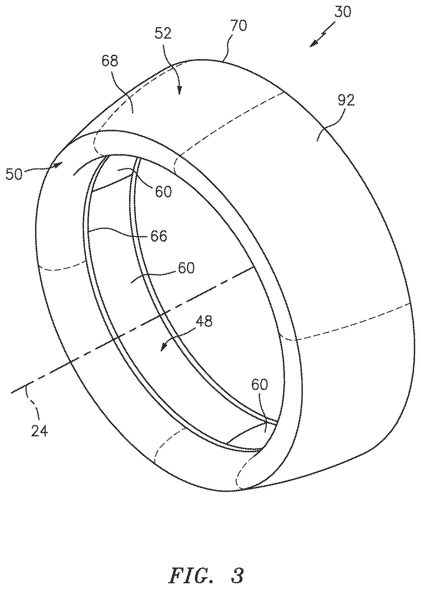
17. The manufacturing method of claim 16, wherein the forming comprises co-curing an entirety of the panel during a single curing cycle.
18. The manufacturing method of claim 16, wherein the forming comprises curing a first composite body; curing a second composite body; and bonding the cured first composite body to the cured second composite body.
19. The manufacturing method of claim 18, wherein the panel further comprises a plurality of corrugations that form the plurality of plenums between the outer skin and the inner skin; the cured first composite body comprises the outer skin; and the cured second composite body comprises at least one of the plurality of corrugations.
20. The manufacturing method of claim 18, wherein the first composite body comprises the outer skin, the second composite body comprises a first corrugation and a second corrugation, and the forming comprises bonding the first corrugation directly to the outer skin; and bonding the second corrugation indirectly to the outer skin through a spacer.
Description
BACKGROUND
1. Technical Field
[0001] This disclosure relates generally to an aircraft system and, more particularly, to an active laminar flow control system and components thereof.
2. Background Information
[0002] It is generally known that laminar flow over an aerodynamic surface, such as an outer surface of a nacelle of an aircraft propulsion system, reduces drag compared to turbulent flow over the same surface. To promote such laminar flow, various active laminar flow control (ALFC) systems have been conceptually developed. Such an ALFC system may include a plenum duct positioned at least partly inside of the nacelle. This plenum duct is fluidly coupled with perforations in the outer surface. The plenum duct is also fluidly coupled with a suction device, which draws air into the plenum duct through the perforations in the outer surface in order to modify airflow over the outer surface. This modification generally removes low energy air from a boundary layer along an extent of the outer surface to prevent that boundary layer from thickening and eventually tripping into a turbulent flow.
[0003] While ALFC systems have various known advantages, these systems are typically difficult to commercially implement due to various deficiencies. There is a need in the art therefore for improved active laminar flow control (ALFC) systems and method for manufacturing such systems.
SUMMARY OF THE DISCLOSURE
[0004] According to an aspect of the present disclosure, an assembly is provided for active laminar flow control. This assembly includes a panel, which panel includes an outer skin, an inner skin and a plurality of plenums between the outer skin and the inner skin. Each of the plurality of plenums is fluidly coupled with a respective array of perforations through the outer skin. The panel is constructed from fiber-reinforced composite material.
[0005] According to another aspect of the present disclosure, another assembly is provided for active laminar flow control. This assembly includes a fiber-reinforced composite panel, which panel includes a radial outer skin, a radial inner skin and a corrugated core forming a plurality of plenums between the radial outer skin and the radial inner skin. Each of the plurality of plenums is fluidly coupled with a respective array of perforations through the radial outer skin.
[0006] According to still another aspect of the present disclosure, a manufacturing method is provided during which a panel for an active laminar flow control system is formed from composite material. The panel includes an outer skin, and inner skin and a plurality of plenums between the outer skin and the inner skin. Each of the plurality of plenums is fluidly coupled with a respective array of perforations through the outer skin.
[0007] The forming may include co-curing an entirety of the panel during a single curing cycle.
[0008] The forming may include curing a first composite body; curing a second composite body; and bonding the cured first composite body to the cured second composite body.
[0009] The panel may also include a plurality of corrugations that form the plurality of plenums between the outer skin and the inner skin. The cured first composite body may be configured as or otherwise include the outer skin. The cured second composite body may be configured as or otherwise include at least one of the plurality of corrugations.
[0010] The first composite body may be configured as or otherwise include the outer skin. The second composite body may include a first corrugation and a second corrugation. The forming may include bonding the first corrugation directly to the outer skin; and bonding the second corrugation indirectly to the outer skin through a spacer.
[0011] The assembly may also include a suction system fluidly coupled with one or more of the plurality of plenums.
[0012] The panel may be configured from the fiber-reinforced composite material as a monolithic body.
[0013] The panel may also include a plurality of corrugations arranged between the outer skin and the inner skin. The plurality of corrugations may form sidewalls of the plurality of plenums.
[0014] A first of the plurality of corrugations may include a bridge, a first sidewall, a second sidewall, a first flange and a second flange. The bridge may extend between the first sidewall and the second sidewall. The bridge may be connected to the inner skin. The first sidewall and the second sidewall may each extend between the inner skin and the outer skin. The first flange may project out from the first sidewall and may be connected to the outer skin. The second flange may project out from the second sidewall and may be connected to the outer skin.
[0015] A first of the plurality of corrugations may be bonded to at least one of the outer skin and the inner skin.
[0016] The panel may also include a spacer. A first of the plurality of corrugations may be connected directly to the outer skin. A second of the plurality of corrugations may be connected indirectly to the outer skin through the spacer.
[0017] A first distance between the outer skin and the inner skin at the first of the plurality of corrugations may be equal to a second distance between the outer skin and the inner skin at the second of the plurality of corrugations.
[0018] The panel may also include a spacer. A first of the plurality of corrugations may be connected directly to the inner skin. A second of the plurality of corrugations may be connected indirectly to the inner skin through the spacer.
[0019] A first portion of the outer skin may have a first thickness. A second portion of the outer skin may have a second thickness that is different from the first thickness.
[0020] The assembly may also include a nacelle for an aircraft propulsion system. The nacelle may include the panel.
[0021] A suction system may be fluidly coupled with each of the plurality of plenums.
[0022] The panel further may also include a plurality of corrugations arranged between the outer skin and the inner skin. The plurality of corrugations may form sidewalls of the plurality of plenums. The panel may be configured from fiber-reinforced composite material as a monolithic body.
[0023] The panel may also include a spacer and a plurality of corrugations arranged between the outer skin and the inner skin. The plurality of corrugations may form sidewalls of the plurality of plenums. A first of the plurality of corrugations may be bonded directly to one of the outer skin and the inner skin. A second of the plurality of corrugations may be bonded indirectly to the one of the outer skin and the inner skin through the spacer.
[0024] The foregoing features and the operation of the invention will become more apparent in light of the following description and the accompanying drawings.
BRIEF DESCRIPTION OF THE DRAWINGS
[0025] FIG. 1 is a schematic side illustration of an aircraft propulsion system with an active laminar flow control (ALFC) system, in accordance with various embodiments;
[0026] FIG. 2 is a schematic side sectional illustration of a forward portion of the aircraft propulsion system of FIG. 1, in accordance with various embodiments;
[0027] FIG. 3 is a perspective illustration of an inlet structure for the aircraft propulsion system of FIG. 1, in accordance with various embodiments;
[0028] FIG. 4 is an end view illustration of the inlet structure of FIG. 3, in accordance with various embodiments;
[0029] FIG. 5 is a sectional illustration of a joint between an inlet lip and an outer barrel of another inlet structure for the aircraft propulsion system of FIG. 1, in accordance with various embodiments;
[0030] FIG. 6 is a sectional illustration of a panel configured for an outer barrel, in accordance with various embodiments;
[0031] FIG. 7 is a perspective illustration of an arcuate section of the panel of FIG. 6, in accordance with various embodiments;
[0032] FIG. 8 is an enlarged sectional illustration of a portion of the panel of FIG. 6, in accordance with various embodiments;
[0033] FIG. 9 is an enlarged sectional illustration of a portion of another panel configured for an outer barrel, in accordance with various embodiments; and
[0034] FIGS. 10-12 are sectional illustrations of respective portions of other panels configured for an outer barrel, in accordance with various embodiments.
DETAILED DESCRIPTION
[0035] FIG. 1 illustrates an aircraft propulsion system 20 for an aircraft such as, but not limited to, a commercial airliner or cargo plane. The propulsion system 20 includes a nacelle 22 and a gas turbine engine. This gas turbine engine may be configured as a high-bypass turbofan engine. Alternatively, the gas turbine engine may be configured as any other type of gas turbine engine capable of propelling the aircraft during flight.
[0036] The nacelle 22 is configured to house and provide an aerodynamic cover for the gas turbine engine. An outer structure of the nacelle 22 extends along an axial centerline 24 between a nacelle forward end 26 and a nacelle aft end 28. The nacelle 22 of FIG. 1 includes a nacelle inlet structure 30, one or more fan cowls 32 (one such cowl visible in FIG. 1) and a nacelle aft structure 34, which may be configured as part of or include a thrust reverser system. However, in other embodiments, the nacelle 22 may be configured without such a thrust reverser system.
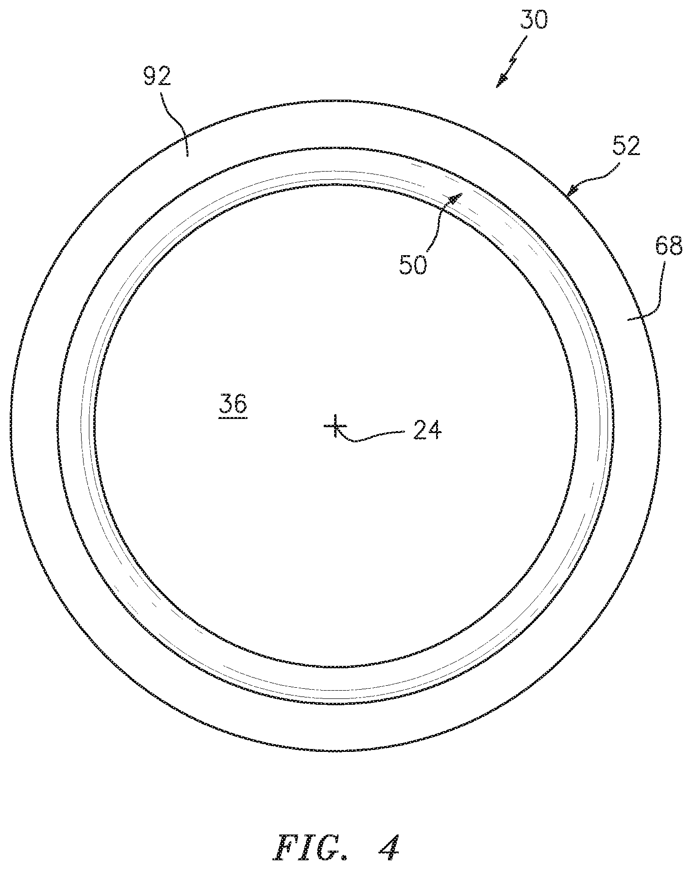
[0037] Briefly, the inlet structure 30 is disposed at the nacelle forward end 26. The inlet structure 30 is configured to direct a stream of air through an inlet opening 36 (see also FIG. 2) at the nacelle forward end 26 and into a fan section of the gas turbine engine.
[0038] The fan cowls 32 are disposed axially between the inlet structure 30 and the aft structure 34. Each fan cowl 32 of FIG. 1, in particular, is disposed at an aft end 38 of a stationary portion of the nacelle 22. Each fan cowl 32 extends axially forward to the inlet structure 30. Each fan cowl 32 is generally axially aligned with a fan section of the gas turbine engine. The fan cowls 32 are configured to provide an aerodynamic covering for a fan case 40; see FIG. 2. Briefly, this fan case 40 circumscribes an array of fan blades in the fan section, and is configured to radially contain one or more of the fan blades and/or fan blade fragments where the blade(s) and/or blade fragment(s) are radially ejected from the fan rotor, for example, after collision with a foreign object. The fan case 40 is also configured to partially form a forward outer peripheral boundary of a bypass flowpath of the propulsion system 20 aft of the fan rotor.
[0039] Referring still to FIG. 1, the term "stationary portion" is used above to describe a portion of the nacelle 22 that is stationary during propulsion system 20 operation (e.g., during takeoff, aircraft flight and landing). However, the stationary portion may be otherwise movable for propulsion system 20 inspection/maintenance; e.g., when the propulsion system 20 is non-operational. Each of the fan cowls 32, for example, may be configured to provide access to components of the gas turbine engine such as the fan case 40 (see FIG. 2) and/or peripheral equipment configured therewith for inspection, maintenance and/or otherwise. In particular, each of fan cowls 32 may be pivotally mounted with the aircraft propulsion system 20 by, for example, a pivoting hinge system. The present disclosure, of course, is not limited to the foregoing exemplary fan cowl configuration and/or access scheme.
[0040] The aft structure 34 may include a translating sleeve 42 for the thrust reverser system. The translating sleeve 42 of FIG. 1 is disposed at the nacelle aft end 28. This translating sleeve 42 extends axially along the axial centerline 24 from a forward end thereof towards (or to) the nacelle aft end 28. The translating sleeve 42 is configured to partially form an aft outer peripheral boundary of the bypass flowpath. The translating sleeve 42 may also be configured to form a bypass nozzle 44 for the bypass flowpath with an inner structure 46 of the nacelle 22 (e.g., an inner fixed structure (IFS)), which nacelle inner structure 46 houses a core of the gas turbine engine.
[0041] Referring now to FIG. 2, the inlet structure 30 may include a tubular inner barrel 48, an annular inlet lip 50, a tubular outer barrel 52 and a bulkhead 54. The inner barrel 48 extends circumferentially around the centerline 24. The inner barrel 48 extends axially along the centerline 24 between an inner barrel forward end 56 and an inner barrel aft end 58, which aft end 58 is positioned axially adjacent and may be connected to a forward end of the fan case 40.
[0042] The inner barrel 48 may be configured to attenuate noise generated during propulsion system 20 operation and, more particularly for example, noise generated by rotation of the fan rotor. The inner barrel 48, for example, may include at least one tubular acoustic panel or an array of arcuate acoustic panels 60 (see FIG. 3) arranged around the centerline 24. Each acoustic panel 60 may include a porous (e.g., honeycomb) core bonded between a perforated face sheet and a non-perforated back sheet, where the perforated face sheet faces radially inward and provides an outer boundary for an axial portion of the gas path. Of course, various other acoustic panel types and configurations are known in the art, and the present disclosure is not limited to any particular ones thereof.
[0043] The inlet lip 50 forms a leading edge of the nacelle 22 as well as the inlet opening 36. The inlet lip 50 has a cupped (e.g., a generally U-shaped or V-shaped) cross-sectional geometry which extends circumferentially around the centerline 24. The inlet lip 50 includes axially overlapping inner and outer lip portions 62 and 64.
[0044] The inner lip portion 62 extends axially from the outer lip portion 64 at the nacelle forward end 26 and the inlet opening 36 to the inner barrel 48. An aft end 66 of the inner lip portion 62 is attached to the inner barrel forward end 56 with, for example, one or more fasteners; e.g., rivets, bolts, etc. The inner lip portion 62 may also or alternatively be bonded (e.g., welded, brazed, adhered, etc.) to the inner barrel 48. Of course, the present disclosure is not limited to any particular attachment techniques between the inlet lip 50 and the inner barrel 48.
[0045] The outer lip portion 64 extends axially from the inner lip portion 62 at the nacelle forward end 26 to the outer barrel 52. The outer lip portion 64 and, more particular, the entire inlet lip 50 may be formed integral with the outer barrel 52. The inlet lip 50 and the outer barrel 52, for example, may be formed from at least a monolithic outer skin 68 such as a formed sheet of molded composite material; e.g., fiber reinforcement within a polymer (e.g., thermoset or thermoplastic resin) matrix. Such a monolithic outer skin 68 may extend longitudinally from the aft end 66 of the inner lip portion 62 to an aft end 70 of the outer barrel 52.
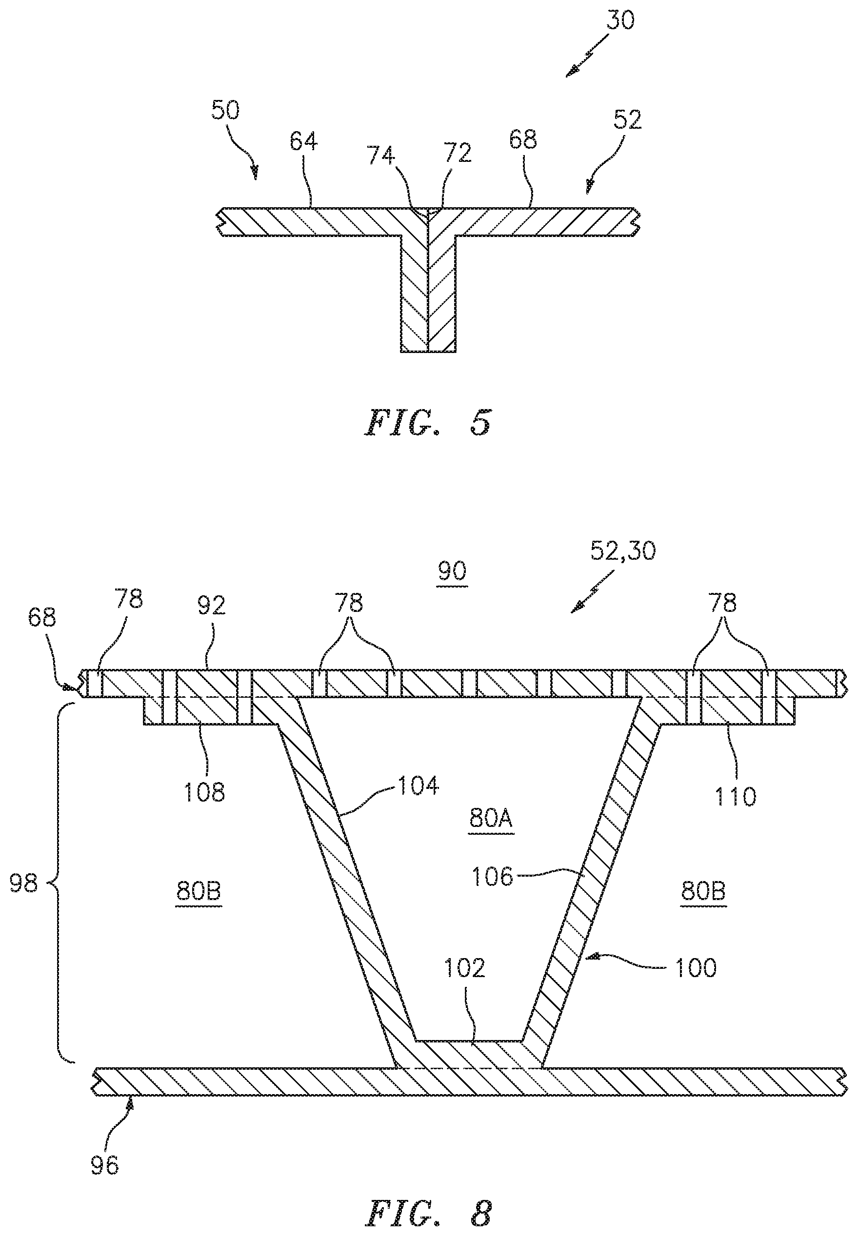
[0046] The inlet lip 50 and the outer barrel 52 may be configured as a single monolithic full hoop body as shown in FIGS. 3 and 4. Alternatively, the inlet lip 50 and the outer barrel 52 may be formed from an array of arcuate segments (e.g., with edges that may correspond to the dashed contour lines shown in FIG. 3) that are attached side-to-side circumferentially about the centerline 24. Of course, in other embodiments, the inlet lip 50 may be formed discrete from the outer barrel 52 as shown in FIG. 5. In such an embodiment, an aft end 72 of the outer lip portion 64 is attached (e.g., mechanically fastened and/or bonded) to a forward end 74 of the outer barrel 52.
[0047] Referring again to FIGS. 2 and 3, the outer barrel 52 extends circumferentially around the centerline 24. Referring to FIG. 2, the outer barrel 52 extends axially along the centerline 24 between the inlet lip 50 and, more particularly, the outer lip portion 64 and the outer barrel aft end 70. The outer barrel 52 may be sized to axially project aft away from the inner barrel 48 and thereby axially cover at least a forward portion of the fan case 40.
[0048] The bulkhead 54 is located approximately axially at (e.g., proximate, adjacent or on) the aft end 66 of the inlet lip 50. The bulkhead 54 may be configured as a substantially annular body. The bulkhead 54 is attached to and extends radially between the inner lip portion 62 and the outer lip portion 64. The bulkhead 54 may be formed integral with the inlet lip 50; e.g., at least the nacelle components 50, 52 and 54 may be configured as a single monolithic body. Alternatively, the bulkhead 54 may be formed discrete from the inlet lip 50 and then mechanically fastened, bonded or otherwise attached to the inlet lip 50.
[0049] The inlet structure 30 of FIGS. 1 and 2 is further configured with an active laminar flow control (ALFC) system 76. This ALFC system 76 includes a plurality of perforations 78 (e.g., see FIGS. 1, 8, 10 and 11; not shown in FIGS. 2-4 and 6 for ease of illustration), a plurality of plenums 80A and 80B (generally referred to as "80") and a suction system 82. The exemplary suction system 82 of FIG. 2 includes a plurality of conduits 84, a manifold 86 and a suction source 88; e.g., a vacuum pump. The present disclosure, however, is not limited to any particular suction system configuration. For example, in other embodiments, the suction system 82 may include one or more manifolds and/or one or more suction sources.
[0050] The perforations 78 are arranged in and extend completely through the outer skin 68; see FIG. 8. Each of the plenums 80 is fluidly coupled with a respective array of the perforations 78 in the outer skin 68. The plenums 80 are thereby fluidly coupled with an external, outside environment 90 to the nacelle 22 and the propulsion system 20 through the respective perforations 78. The conduits 84 respectively fluidly couple the plenums 80 to the manifold 86, which manifold 86 in turn fluidly couples the conduits 84 to the suction source 88. With this arrangement, the ALFC system 76 is adapted to direct (e.g., pull) boundary layer air flowing along the outer skin 68 in the environment 90 sequentially through the ALFC system elements 78, 80, 84 and 86 to the suction source 88, whereby pulling the boundary layer air into the perforations 78 may aid in facilitating laminar flow along the along an outer surface 92 of the inlet structure 30. The general principals of active laminar flow control are well known and therefore are not described herein in further detail.
[0051] Referring to FIG. 6, the plenums 80 are integrated into/embedded within one or more panels 94 (see also FIG. 1). Each of these panels 94 may be configured as an integral portion of the inlet structure 30 and, more particularly, the outer barrel 52. The panel 94 of FIG. 6, for example, includes a respective portion of the outer skin 68 (here a radial outer skin), a respective portion of an inner skin 96 (here a radial inner skin) and a corrugated core section 98, which extends and is connected between the outer skin 68 and the inner skin 96.
[0052] The corrugated core section 98 of FIG. 6 includes a plurality of axially side-by-side corrugations 100. Each of these corrugations 100 may be configured as a longitudinally (e.g., circumferentially relative to the centerline 24) elongated hollow-hat channel structure; see also FIG. 7. The exemplary corrugation 100 of FIG. 8, for example, includes a bridge 102, a first sidewall 104, a second sidewall 106, a first flange 108 and a second flange 110. The bridge 102 extends laterally (e.g., generally axially relative to the centerline 24) between the first sidewall 104 and the second sidewall 106. The bridge 102 of FIG. 8 may lay flush against and is connected (e.g., directly) to the inner skin 96. The first sidewall 104 extends vertically (e.g., generally radially relative to the centerline 24) and laterally between an end of the bridge 102 and an end of the first flange 108 as well as between the inner skin 96 and the outer skin 68. Similarly, the second sidewall 106 extends vertically and laterally between an end of the bridge 102 and an end of the second flange 110 as well as between the inner skin 96 and the outer skin 68. The first flange 108 projects laterally out from the first sidewall 104 to a distal end, which forms a first side of the corrugation 100. The first flange 108 of FIG. 8 may lay flush against and is connected (e.g., bonded directly) to the outer skin 68. The second flange 110 projects laterally out from the second sidewall 106 to a distal end, which forms a second side of the corrugation 100. The second flange 110 of FIG. 8 may lay flush against and is connected (e.g., bonded directly) to the outer skin 68.
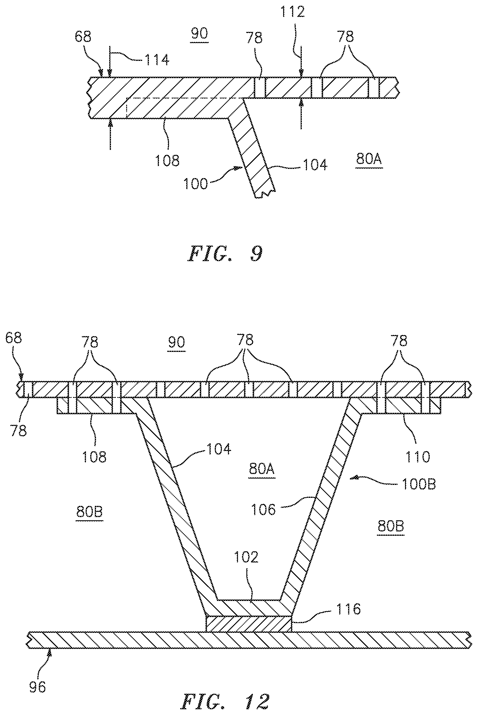
[0053] With the foregoing configuration, the corrugations 100 along with the inner skin 96 are operable to provide a reinforcement/backbone structure for the outer skin 68. As a result, a vertical thickness of the outer skin 68 may be sized smaller than if the corrugations 100 and inner skin 96 were not provided. This may enable the vertical thickness of the entire outer skin 68 to be decreased. Alternatively, the vertical thickness at 112 of a portion of the outer skin 68 connected to the corrugations 100 may be sized less than the vertical thickness at 114 of an adjacent (e.g., unsupported) portion of the outer skin 68 as shown in FIG. 9. As a result, an overall weight of the inlet structure 30 may be reduced.
[0054] Referring to FIG. 6, the plenums 80 may be grouped into one or more first plenums 80A and one or more second plenums 80B. Each first plenum 80A is arranged within the panel 94 vertically between the outer skin 68 and the inner skin 96. More particularly, each first plenum 80A extends vertically between a respective bridge 102 and the outer skin 68; see also FIG. 8. Each first plenum 80A extends laterally between the first and the second sidewalls 104 and 106 of a respective one of the corrugations 100. Referring to FIG. 7, each first plenum 80A extends longitudinally within the panel 94, where a longitudinal length of each first plenum 80A may be significantly (e.g., 10.times., 20.times., 30.times. or more) greater than a lateral length and/or vertical height of that first plenum 80A.
[0055] Referring to FIG. 6, each second plenum 80B is arranged within the panel 94 vertically between the outer skin 68 and the inner skin 96. More particularly, each second plenum 80B extends vertically between the inner skin 96, the outer skin 68 and respective flanges of two laterally adjacent corrugations 100. Each second plenum 80B extends laterally between the first and the second sidewalls 104 and 106 of the two laterally adjacent corrugations 100. Referring to FIG. 7, each second plenum 80B extends longitudinally within the panel 94, where a longitudinal length of each second plenum 80B may be significantly (e.g., 10.times., 20.times., 30.times. or more) greater than a lateral length and/or vertical height of that second plenum 80B. It is worth noting, at least some of the perforations 78 fluidly coupled with each second plenum 80B may also extend completely through the respective flanges 108 and 110 as shown in FIG. 8. However, the present disclosure is not limited to such an embodiment. For example, in other embodiments, one or more of the flanges 108 and/or 110 may be non-perforated.
[0056] The panel 94 of FIGS. 6 and 7 and, more generally, the inlet structure 30 and each of its elements may be configured from composite material; e.g., fiber-reinforced composite material. This composite material may include reinforcement fibers embedded within a polymer matrix; e.g., thermoset or thermoplastic resin. Examples of reinforcement fibers include, but are not limited to, fiberglass fibers, carbon-fiber fibers, aramid (e.g., Kevlar.RTM.) fibers and/or a combination thereof.
[0057] In some embodiments, each panel 94 as well as the outer barrel 52 and/or the inlet structure 30 as a whole may be configured from the composite material as a monolithic body. The reinforcement fibers, for example, may be laid up in a mold collectively in the shape of the panel 94 in its entirety. The reinforcement fibers may then be impregnated with resin. Of course, in other embodiments, the reinforcement fibers may also or alternatively be pre-impregnated before the layup. The resin in the laid-up material may subsequently be cured such that the various elements (e.g., 68, 96, 98 and 100) of the entire panel 94 are co-cured together during a single curing cycle to form the panel 94 body. Subsequent to this curing cycle, the outer skin 68 and, as needed, one or more of the flanges 108 and/or 110 are perforated to form the perforations 78. This perforation process may be performed using a laser, a mechanical drill and/or any other suitable material perforation device.
[0058] In some embodiments, one or more elements (e.g., 68, 96 and/or 100) of a panel may be formed using different curing cycles. For example, a first body corresponding to the outer skin 68 may be laid-up, impregnated and then cured during a first curing cycle. A second body corresponding to the corrugated core section 98 and one or more of its corrugations 100 may be laid-up, impregnated and then cured during a second curing cycle. A third body corresponding to the inner skin 96 may be laid-up, impregnated and then cured during a third curing cycle. These three bodies may subsequently be adhered with resin and/or otherwise bonded together to form the panel 94 body. Subsequent to this bonding, the outer skin 68 and, as needed, one or more of the flanges 108 and/or 110 are perforated to form the perforations 78. Alternatively, the outer skin 68 may be perforated prior to the bonding; however, some of these perforations 78 may be covered/blocked by the flanges 108 and/or 110. As a result, an additional perforating process may (or may not) be performed to perforate the flanges 108 and/or 110.
[0059] While three different lay-up and curing steps are described above, the present disclosure is not limited to such a formation methodology. For example, in other embodiments, a method for manufacturing the panel 94 may combine the laying-up and co-curing of the elements 68 and 98/100 or the elements 96 and 98/100.
[0060] In some embodiments, the panel 94 may be configured with one or more spacers 116 as illustrated, for example, in FIGS. 10 and 11. Such spacers 116 may be used to compensate for irregularities/manufacturing tolerances in the corrugated core section 98. For example, during manufacture, one of the corrugations 100A may have a (e.g., slightly) different vertical height than another one of the corrugations 100B. The spacers 116 may be bonded between the smaller/shorter corrugation 100B (e.g., one or both of its flanges 108 and/or 110) and the outer skin 68 such that the vertical distance between the skins 68 and 96 at the non-spaced corrugation 100A is the same as (or alternatively different than) the vertical distance between the skins 68 and 96 at the spaced corrugation 100B. Thus, the spaced corrugation 100B is connected (e.g., bonded indirectly) to the outer skin 68 through the spacers 116. In the embodiment of FIG. 10, the spacer 116 (or shim) is configured with the vertical thickness that is equal to or less than the vertical thicknesses of the outer skin 68 and/or the flanges 108 and/or 110. In the embodiment of FIG. 11, the spacer 116 is configured with the vertical thickness that is (e.g., at least 2-5.times.) greater than the vertical thicknesses of the outer skin 68 and/or the flanges 108 and/or 110.
[0061] In some embodiments, one or more spacers 116 may also or alternatively be bonded between a respective corrugation 100 (e.g., its bridge 102) and the inner skin 96 as shown in FIG. 12.
[0062] The panels 94 are described above as being integral portions of the outer barrel 52 and the inlet structure 30; e.g., sharing a common outer skin and a common inner skin. However, in other embodiments, each panel 94 may be configured with a discrete inner skin. In still other embodiments, each panel 94 may be configured with a discrete outer skin.
[0063] The ALFC system 76 is described above as being configured with the aircraft propulsion system 20. However, the present disclosure is not limited to aircraft propulsion system applications. For example, in other embodiments, the ALFC system 76 may be configured for promoting laminar flow along a surface of a wing or any other component of an aircraft. In still other embodiments, the ALFC system 76 may be configured with other non-aircraft vehicles. The present disclosure therefore is not limited to propulsion system or aircraft applications.
[0064] While various embodiments of the present invention have been disclosed, it will be apparent to those of ordinary skill in the art that many more embodiments and implementations are possible within the scope of the invention. For example, the present invention as described herein includes several aspects and embodiments that include particular features. Although these features may be described individually, it is within the scope of the present invention that some or all of these features may be combined with any one of the aspects and remain within the scope of the invention. Accordingly, the present invention is not to be restricted except in light of the attached claims and their equivalents.
* * * * *
D00000
D00001
D00002
D00003
D00004
D00005
D00006
D00007
D00008
D00009
XML
uspto.report is an independent third-party trademark research tool that is not affiliated, endorsed, or sponsored by the United States Patent and Trademark Office (USPTO) or any other governmental organization. The information provided by uspto.report is based on publicly available data at the time of writing and is intended for informational purposes only.
While we strive to provide accurate and up-to-date information, we do not guarantee the accuracy, completeness, reliability, or suitability of the information displayed on this site. The use of this site is at your own risk. Any reliance you place on such information is therefore strictly at your own risk.
All official trademark data, including owner information, should be verified by visiting the official USPTO website at www.uspto.gov. This site is not intended to replace professional legal advice and should not be used as a substitute for consulting with a legal professional who is knowledgeable about trademark law.