Continuous Casting Method And Continuous Casting Device
Honda; Yuki ; et al.
U.S. patent application number 16/490251 was filed with the patent office on 2020-01-09 for continuous casting method and continuous casting device. The applicant listed for this patent is NIPPON STEEL STAINLESS STEEL CORPORATION. Invention is credited to Yuki Honda, Hiroshi Morikawa, Yasuhiro Suzuki.
| Application Number | 20200009650 16/490251 |
| Document ID | / |
| Family ID | 63370093 |
| Filed Date | 2020-01-09 |


| United States Patent Application | 20200009650 |
| Kind Code | A1 |
| Honda; Yuki ; et al. | January 9, 2020 |
CONTINUOUS CASTING METHOD AND CONTINUOUS CASTING DEVICE
Abstract
Capture of a foreign matter into a solidified shell is effectively suppressed. A continuous casting method is a method which is carried out with use of a continuous casting device, and includes: a discharging step of discharging molten steel through a discharge hole; and a stirring step of stirring the molten steel so that a stirring region includes a whole line segment via which the discharge hole and a reached location are connected to each other, the reached location being a location on a surface of the molten steel in a mold which location is reached by the molten steel in a case where the molten steel discharged in the discharging step proceeds straight.
| Inventors: | Honda; Yuki; (Tokyo, JP) ; Morikawa; Hiroshi; (Yamaguchi, JP) ; Suzuki; Yasuhiro; (Tokyo, JP) | ||||||||||
| Applicant: |
|
||||||||||
|---|---|---|---|---|---|---|---|---|---|---|---|
| Family ID: | 63370093 | ||||||||||
| Appl. No.: | 16/490251 | ||||||||||
| Filed: | March 2, 2018 | ||||||||||
| PCT Filed: | March 2, 2018 | ||||||||||
| PCT NO: | PCT/JP2018/008066 | ||||||||||
| 371 Date: | August 30, 2019 |
| Current U.S. Class: | 1/1 |
| Current CPC Class: | B22D 41/62 20130101; B22D 11/115 20130101; B22D 41/50 20130101 |
| International Class: | B22D 41/62 20060101 B22D041/62; B22D 11/115 20060101 B22D011/115 |
Foreign Application Data
| Date | Code | Application Number |
|---|---|---|
| Mar 3, 2017 | JP | 2017-040658 |
| Jul 4, 2017 | JP | PCT/JP2017/024528 |
Claims
1. A continuous casting method which is carried out with use of a continuous casting device, the continuous casting device including: a mold which includes a first surface and a second surface, which intersects the first surface, so as to have a surrounding structure; a submerged nozzle which has a discharge hole through which molten steel is discharged; and a stirring device which forms a stirring region by stirring the molten steel in the mold, the method comprising: a discharging step of discharging, through the discharge hole located in the mold, the molten steel upward with respect to a horizontal direction and in a direction parallel to the first surface; and a stirring step of stirring the molten steel so that the stirring region includes a whole line segment via which the discharge hole and a reached location are connected to each other, the reached location being a location on a surface of the molten steel in the mold or on the second surface which location is reached by the molten steel in a case where the molten steel discharged in the discharging step proceeds straight.
2. The method as set forth in claim 1, wherein a flow velocity of the molten steel in the stirring region falls within a range of 0.20 m/s to 0.40 m/s.
3. The method as set forth in claim 1, wherein the reached location is the location on the surface.
4. The method as set forth in claim 1, wherein an impulse which the molten steel, discharged from the submerged nozzle, receives by a time when the molten steel reaches the surface is 0.4.times.107 G.sup.2/.mu..OMEGA.-m to 2.5.times.107 G.sup.2/.mu..OMEGA.-m.
5. A continuous casting device comprising: a mold which includes a first surface and a second surface, which intersects the first surface, so as to have a surrounding structure; a submerged nozzle which has a discharge hole located in the mold and from which molten steel is discharged in a direction parallel to the first surface through the discharge hole; and a stirring device which forms a stirring region by stirring the molten steel in the mold, the discharge hole being included in the stirring region and causing the molten steel to be discharged upward with respect to a horizontal direction, the stirring device stirring the molten steel so that the stirring region includes a whole line segment via which the discharge hole and a reached location are connected to each other, the reached location being a location on a surface of the molten steel in the mold or on the second surface which location is reached by the molten steel in a case where the molten steel discharged through the discharge hole proceeds straight.
6. The continuous casting device as set forth in claim 5, wherein a flow velocity of the molten steel in the stirring region falls within a range of 0.20 m/s to 0.40 m/s.
7. The continuous casting device as set forth in claim 5, wherein the discharge hole causes the molten steel to be discharged upward at an angle of 5.degree. to 30.degree. with respect to a horizontal plane.
8. The continuous casting device as set forth in claim 5, wherein an impulse which the molten steel, discharged from the submerged nozzle, receives by a time when the molten steel reaches the surface is 0.4.times.107 G.sup.2/.mu..OMEGA.-m to 2.5.times.107 G.sup.2/.mu..OMEGA.-m.
Description
TECHNICAL FIELD
[0001] The present invention relates to a method and a device for continuously casting steel while carrying out electromagnetic stirring.
BACKGROUND ART
[0002] In continuous casting of steel, there is a problem that a foreign matter, such as an air bubble and an oxide, which is inevitably incorporated into molten steel in a mold is captured into a solidified shell and, consequently, a defect (flaw) is formed on a surface of a steel sheet (slab) obtained through a hot rolling step or a cool rolling step. As a solution to the problem, electromagnetic stirring is widely employed. By the electromagnetic stirring, a flow of the molten steel in the mold is controlled so that the foreign matter in the molten steel is floated and is then captured by a mold powder applied to a surface of the molten steel. Patent Literature 1discloses an example of such a method.
[0003] In the technique disclosed in Patent Literature 1, a submerged nozzle is used which has two discharge holes through each of which molten metal is discharged upward at an angle of 5.degree. to 30.degree.. Through the two discharge holes, the molten metal is discharged toward short sides of a mold. Then, by electromagnetic stirring, a driving force acting in a direction perpendicular to a casting direction is applied to the molten metal in a vicinity of a meniscus near each of two long-side surfaces of the mold. With this configuration, a temperature of the molten metal in a vicinity of its surface is kept high, and a flow of the molten metal, which flow is uniform and perpendicular to the casting direction, is formed.
CITATION LIST
Patent Literature
[0004] [Patent Literature 1]
[0005] Japanese Patent Application Publication Tokukaihei No. 10-166120 (Published on Jun. 23, 1998)
SUMMARY OF INVENTION
Technical Problem
[0006] However, Patent Literature 1 does not clearly disclose a method of forming a stirring flow for increasing cleaning of a foreign matter from the molten metal. Thus, the technique disclosed in Patent Literature 1 has a problem that an effect of suppressing capture of a foreign matter into a solidified shell is not sufficient.
[0007] An object of an aspect of the present invention is to effectively suppress capture of a foreign matter into a solidified shell.
Solution to Problem
[0008] In order to attain the above object, a continuous casting method in accordance with an aspect of the present invention is a continuous casting method which is carried out with use of a continuous casting device, the continuous casting device including: a mold which includes a first surface and a second surface, which intersects the first surface, so as to have a surrounding structure; a submerged nozzle which has a discharge hole through which molten steel is discharged; and a stirring device which forms a stirring region by stirring the molten steel in the mold, the method including: a discharging step of discharging, through the discharge hole located in the mold, the molten steel upward with respect to a horizontal direction and in a direction parallel to the first surface; and a stirring step of stirring the molten steel so that the stirring region includes a whole line segment via which the discharge hole and a reached location are connected to each other, the reached location being a location on a surface of the molten steel in the mold or on the second surface which location is reached by the molten steel in a case where the molten steel discharged in the discharging step proceeds straight.
[0009] The continuous casting method in accordance with an aspect of the present invention is arranged such that a flow velocity of the molten steel in the stirring region falls within a range of 0.20 m/s to 0.40 m/s.
[0010] The continuous casting method in accordance with an aspect of the present invention can be arranged such that the reached location is the location on the surface.
[0011] The continuous casting method in accordance with an aspect of the present invention is preferably arranged such that an impulse which the molten steel, discharged from the submerged nozzle, receives by a time when the molten steel reaches the surface is 0.4.times.10.sup.7 G.sup.2/.mu..OMEGA.-m to 2.5.times.10.sup.7 G.sup.2/.mu..OMEGA.-m.
[0012] A continuous casting device in accordance with an aspect of the present invention is a continuous casting device including: a mold which includes a first surface and a second surface, which intersects the first surface, so as to have a surrounding structure; a submerged nozzle which has a discharge hole located in the mold and from which molten steel is discharged in a direction parallel to the first surface through the discharge hole; and a stirring device which forms a stirring region by stirring the molten steel in the mold, the discharge hole being included in the stirring region and causing the molten steel to be discharged upward, the stirring device stirring the molten steel so that the stirring region includes a whole line segment via which the discharge hole and a reached location are connected to each other, the reached location being a location on a surface of the molten steel in the mold or on the second surface which location is reached by the molten steel in a case where the molten steel discharged through the discharge hole proceeds straight.
[0013] The continuous casting device in accordance with an aspect of the present invention is arranged such that a flow velocity of the molten steel in the stirring region falls within a range of 0.20 m/s to 0.40 m/s.
[0014] The continuous casting device in accordance with an aspect of the present invention is preferably arranged such that the discharge hole causes the molten steel to be discharged upward at an angle of 5.degree. to 30.degree. with respect to a horizontal plane.
[0015] The continuous casting device in accordance with an aspect of the present invention is preferably arranged such that an impulse which the molten steel, discharged from the submerged nozzle, receives by a time when the molten steel reaches the surface is 0.4.times.10.sup.7 G.sup.2/.mu..OMEGA.-m to 2.5.times.10.sup.7 G.sup.2/.mu..OMEGA.-m.
Advantageous Effects of Invention
[0016] According to an aspect of the present invention, it is possible to effectively suppress capture of a foreign matter into a solidified shell.
BRIEF DESCRIPTION OF DRAWINGS
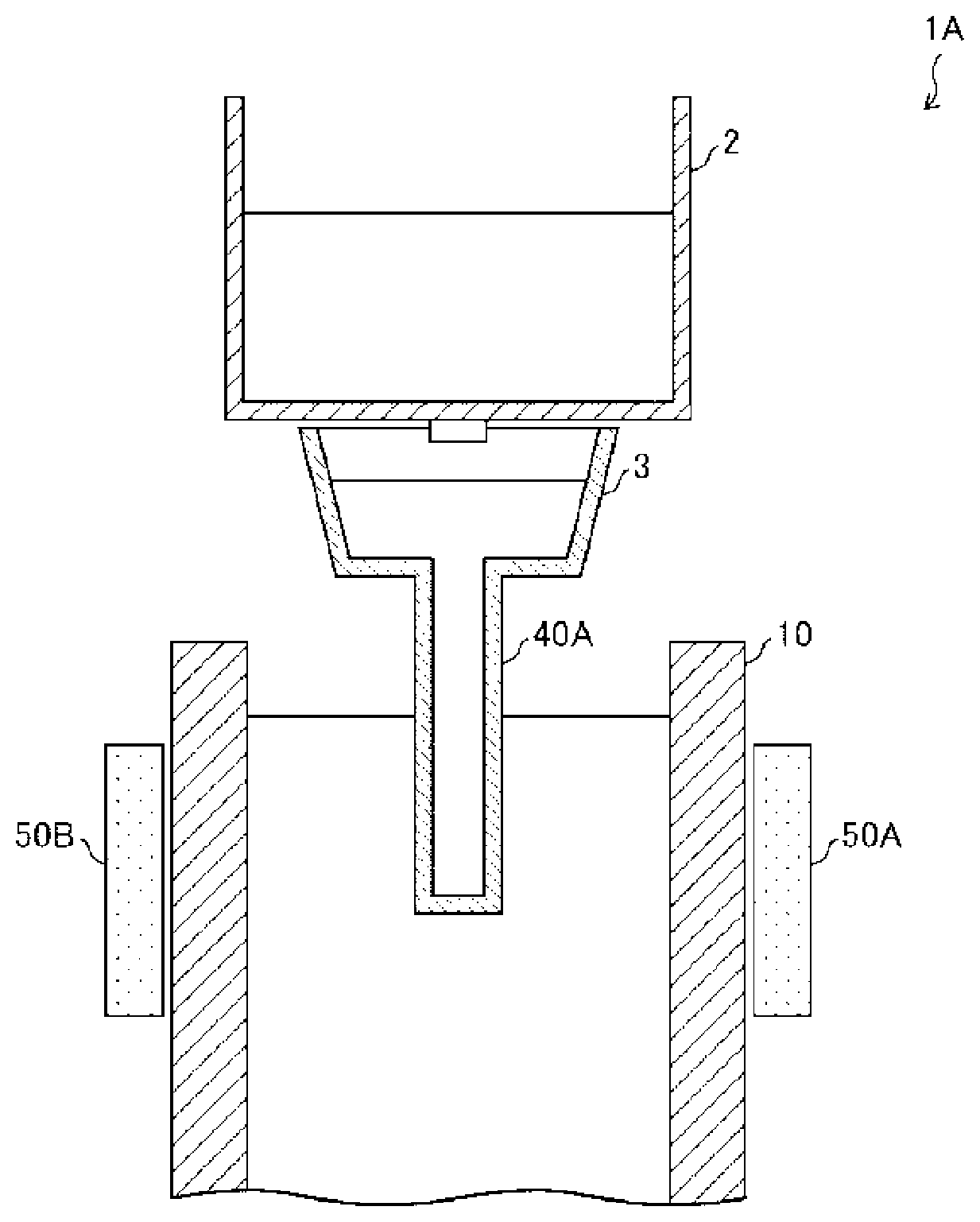
[0017] FIG. 1 is a schematic view illustrating a configuration of a continuous casting device in accordance with Embodiment 1 of the present invention.
[0018] FIG. 2 is a cross-sectional view of the continuous casting device, obtained by cutting the continuous casting device along a horizontal plane at a height of a surface of molten steel in a mold included in the continuous casting device.
[0019] FIG. 3 is a cross-sectional view of a vicinity of the surface of the molten steel in the continuous casting device, obtained by cutting the continuous casting device along a plane which passes through a center of the mold and which is parallel to long-side molds included in the mold.
[0020] FIG. 4 is a cross-sectional view of the vicinity of the surface of the molten steel in the continuous casting device, obtained by cutting the continuous casting device along a plane which passes through the center of the mold and which is parallel to short-side molds included in the mold.
[0021] FIG. 5 is a cross-sectional view of a continuous casting device in accordance with Embodiment 2 of the present invention, and is a cross-sectional view of a vicinity of a surface of molten steel in the continuous casting device, obtained by cutting the continuous casting device along a plane which passes through a center of a mold included in the continuous casting device and which is parallel to long-side molds included in the mold.
[0022] FIG. 6 shows the numbers of macro-streak-flaws per square millimeter on each of an example strand of the present invention and a comparative example strand. (a) of FIG. 6 is a graph showing the numbers of macro-streak-flaws present at a location 2 mm below a surface layer. (b) of FIG. 6 is a graph showing the numbers of macro-streak-flaws present at a location 3 mm below the surface layer.
DESCRIPTION OF EMBODIMENTS
[0023] The following description will discuss a continuous casting device 1A and a continuous casting method in accordance with Embodiment 1 of the present invention with reference to FIGS. 1 through 4. As used herein, an expression "A to B" means "not less than A and not more than B".
[0024] FIG. 1 is a schematic view illustrating a configuration of the continuous casting device 1A. As illustrated in FIG. 1, the continuous casting device 1A includes a ladle 2, a tundish 3, a mold 10, a submerged nozzle (discharge nozzle) 40A, and electromagnetic stirring devices (stirring devices) 50A and 50B. The ladle 2 receives molten steel supplied from a steel converter.
[0025] The tundish 3 is a member for storing the molten steel transferred from the ladle 2 and removing a foreign matter such as an oxide. The molten steel stored in the tundish 3 is transferred into the mold 10 through the submerged nozzle 40A (later described).
[0026] The mold 10 is a mold for cooling the molten steel thus transferred so that a solidified shell C is formed against an inner surface of the mold 10. The solidified shell C is sent out from a bottom of the mold 10. FIG. 2 is a cross-sectional view of the continuous casting device 1A, obtained by cutting the continuous casting device 1A along a horizontal plane at a height of a surface S of molten steel in the mold 10. As illustrated in FIG. 2, a contour shape of the inner surface of the mold 10 cut at the horizontal plane is a rectangular shape. The mold 10 includes (i) long-side molds 11A and 11B facing each other and (ii) short-side molds 12A and 12B facing each other. The long-side molds 11A and 11B have long-side surfaces (first surface) 11Aa and 11Ba, respectively, which form the inner surface of the mold 10. The short-side molds 12A and 12B have short-side surfaces (second surface) 12Aa and 12Ba, respectively, which form the inner surface of the mold 10. In other words, the long-side surfaces 11Aa and 11Ba and the short-side surfaces 12Aa and 12Ba which intersect the long-side surfaces 11Aa and 11Ba form a surrounding structure. Hereinafter, a horizontal direction which is parallel to the long-side molds 11A and 11B will be referred to as a "long-side direction LD", and the horizontal direction which is parallel to the short-side molds 12A and 12B will be referred to as a "short-side direction SD" (see FIG. 2).
[0027] The submerged nozzle 40A is a member for transferring, into the mold 10, the molten steel stored in the tundish 3. The submerged nozzle 40A is provided so that an upper end of the submerged nozzle 40A is connected to the tundish 3 and a lower end of the submerged nozzle 40A is located substantially at a center of the mold 10 (that is, in FIG. 2, substantially at a center of the rectangular shape formed by the long-side surfaces 11Aa and 11Ba and the short-side surfaces 12Aa and 12Ba).
[0028] FIG. 3 is a cross-sectional view of a vicinity of the surface S in the continuous casting device 1A, obtained by cutting the continuous casting device 1A along a plane which passes through the center of the mold 10 and which is parallel to the long-side molds 11A and 11B of the mold 10. Note that, since the continuous casting device 1A has a structure symmetrical about the submerged nozzle 40A, FIG. 3 illustrates a region which includes the submerged nozzle 40A and the short-side mold 12B, in a state where the region is enlarged. The submerged nozzle 40A has two discharge holes 41A, as illustrated in FIG. 3. The two discharge holes 41A are each located inside the mold 10, and are each a hole for discharging the molten steel which has been supplied from tundish 3 and which has passed through an inside of the submerged nozzle 40A. The two discharge holes 41A are formed on respective sides of the submerged nozzle 40A which sides are located in the long-side direction LD. Through the two discharge holes 41A, the molten steel is discharged in directions each parallel to the long-side surfaces 11Aa and 11Ba. Each of the two discharge holes 41A is formed so that a discharge direction 60 of a discharge flow is directed upward with respect to the horizontal plane. Hereinafter, an angle formed by the discharge direction 60 of each of the two discharge holes 41A and the horizontal plane will be referred to as a discharge angle .theta..
[0029] According to the continuous casting device 1A, the molten steel is continuously supplied to the mold 10 through the two discharge holes 41A of the submerged nozzle 40A, and the surface S (also referred to as a meniscus) of the molten steel is formed at a given height inside the mold 10. Note that, although the surface S swings to an extent during continuous casting, an average height of the surface S is regarded as a location of the surface S in the present specification. Note also that a mold powder (not illustrated) for capturing a foreign matter such as an air bubble and an oxide is applied to the surface S.
[0030] The electromagnetic stirring devices 50A and 50B are devices for causing, by electromagnetic forces, a stirring flow (swirling flow) with respect to the molten steel in the vicinity of the surface S in the mold 10. FIG. 4 is a cross-sectional view of a vicinity of the surface S in the continuous casting device 1A, obtained by cutting the continuous casting device 1A along a plane which passes through the center of the mold 10 and which is parallel to the short-side molds 12A and 12B of the mold 10. The electromagnetic stirring devices 50A and 50B are provided on back surfaces of the long-side molds 11A and 11B, respectively, as illustrated in FIG. 4. The electromagnetic stirring devices 50A and 50B include stirring coil cores 51A and 51B, respectively. Each of the stirring coil cores 51A and 51B applies an electromagnetic force to the molten steel in the mold 10, at a height at which the each of the stirring coil cores 51A and 51B is provided. Specifically, the stirring coil core 51 A of the electromagnetic stirring device 50A applies, to the molten steel in a vicinity of the long-side mold 11A, an electromagnetic force parallel to the long-side direction LD. Similarly, the stirring coil core 51B of the electromagnetic stirring device 50B applies, to the molten steel in a vicinity of the long-side mold 11B, an electromagnetic force parallel to the long-side direction LD. Note, however, that the continuous casting device 1A is configured such that a direction of the electromagnetic force applied to the molten steel by the stirring coil core 51A and a direction of the electromagnetic force applied to the molten steel by the stirring coil core 51B are opposite to each other. This causes a stirring flow to be formed in the horizontal direction in the vicinity of the surface S in the mold 10 (see an black arrows in FIG. 2). In Embodiment 1, the electromagnetic stirring devices 50A and 50B are provided so that respective upper ends of the stirring coil cores 51A and 51B are each located a given distance below the surface S.
[0031] In FIG. 4, a region A1 indicates a region between an upper end and a lower end of each of the two discharge holes 41A, which upper end and lower end are located in a vertical direction. As illustrated in FIG. 4, the stirring coil cores 51A and 51B are provided so as to include, in the vertical direction, the whole two discharge holes 41A. With this configuration, electromagnetic forces are applied, by the stirring coil cores 51A and 51B, to the molten steel discharged through the two discharge holes 41A from a time point when the molten steel is discharged.
[0032] The electromagnetic stirring devices 50A and 50B cause a stirring flow with respect to the molten steel in the mold 10. Note, here, that the stirring flow is not formed only in a region located at the height at which each of the stirring coil cores 51A and 51B is provided. That is, in a case where a stirring flow is caused in a region A2 in which the stirring coil cores 51A and 51B are provided, the molten steel, present in regions each extending upward or downward from the region A2 by a certain distance, is also caused to swirl in the mold 10, so that a stirring flow is caused. In the present specification, a region including the region A2 and the "regions each extending upward or downward from the region A2 by a certain distance" will be referred to as a stirring region A3 which is formed by the electromagnetic stirring devices 50A and 50B (see FIG. 4). Specifically, the stirring region A3 in the present specification means a region in which a flow velocity of the molten steel falls within a range of 0.20 m/s to 0.40 m/s. It known that, in a case where a flow velocity of molten steel in a vicinity of a surface S falls within a range of 0.20 m/s to 0.40 m/s, it is possible to reduce both a surface defect and an internal defect of steel to be produced. According to the continuous casting device 1A in accordance with Embodiment 1, the stirring coil cores 51A and 51B are provided so that the stirring region A3 includes the surface S.
[0033] Note that the continuous casting device 1A is configured such that the electromagnetic stirring devices 50A and 50B are provided so that the respective upper ends of the stirring coil cores 51A and 51B are each located the given distance below the surface S. However, the continuous casting device in accordance with an embodiment of the present invention is not limited to such a configuration, and can be alternatively configured such that the respective upper ends of the stirring coil cores 51A and 51B are each located at a height corresponding to the height of the surface S or each located above the surface S. Also in such cases, it is possible to configure the continuous casting device so that the stirring region includes the surface S.
[0034] The continuous casting device 1A in accordance with Embodiment 1 is configured as follows. That is, a substantially whole amount of the molten steel discharged through each of the two discharge holes 41A of the submerged nozzle 40A is caused to reach the surface S, by appropriately setting the discharge angle .theta., a distance L between (i) a center of each of the two discharge holes 41A and (ii) the surface S, and a distance W between the short-side molds 12A and 12B (that is, a length of each of the long-side surfaces 11Aa and 11Ba in the horizontal direction).
[0035] Here, the following description will discuss, with reference to FIG. 3, a "reached location" on the surface S which location is reached by the discharge flow caused by the molten steel discharged through a discharge hole 41A. As illustrated in FIG. 3, a center of an opening of the discharge hole 41A is regarded as a starting point, and a point at which the surface S intersects a half line extending in the discharge direction 60 from the starting point is regarded as a point P. In other words, the point P is a point on the surface S which point is reached by the molten steel, discharged through the discharge hole 41A, in a case where the molten steel discharged through the discharge hole 41A proceeds straight. The discharge flow from the discharge hole 41A proceeds through the molten steel in the mold 10 while spreading to some extent. By setting a discharge velocity, at which the molten steel is discharged through the discharge hole 41A, so as to be higher than a given velocity, it is possible to cause the substantially whole amount of the molten steel discharged through the discharge hole 41A to directly reach the point P and the surface S in a vicinity of the point P. In Embodiment 1, the point P and the vicinity of the point P will be referred to as a "reached location". In Embodiment 1, the stirring region A3 incudes a whole line segment via which the center of the opening of the discharge hole 41A and the point P are connected to each other.
[0036] Note that, in a case where the discharge angle .theta. is excessively wide or in a case where the distance L is excessively short, the surface S excessively ruffles because the discharge flow from the discharge hole 41A directly reaches the surface S (reached location), so that the mold powder present on the surface S is highly likely to be entrapped in the solidified shell C as a foreign matter. Therefore, the discharge angle .theta. is preferably not more than 30.degree.. In a case where a velocity of the discharge flow is 300 mm/s to 1150 mm/s, the distance L is preferably not less than 180 mm.
[0037] In a case where the distance L is excessively long, time it takes for the discharge flow to reach the surface S (reached location) becomes longer. As a result, time it takes for a high-temperature discharge flow to reach the surface S in a vicinity of each of the short-side molds 12A and 12B becomes longer, and a temperature of the surface S of the molten steel in the vicinity of each of the short-side molds 12A and 12B becomes lower. A decrease in a temperature of the molten steel causes generation of an ununiform initial solidified shell having a hook-like cross section. This ultimately causes an increase in entrapment of a foreign matter into the solidified shell C. Therefore, in a case where the velocity of the discharge flow is 300 mm/s to 1150 mm/s, the distance L is preferably not more than 230 mm.
[0038] As an example of the configuration of the continuous casting device 1A, in a case where the distance W is longer than 520 mm, it is possible to cause the substantially whole amount of the molten steel discharged through the discharge hole 41A of the submerged nozzle 40A to reach the surface S (reached location), by setting the discharge angle .theta. to 30.degree. and setting the distance L to 150 mm (for example, setting a width, in an up-and-down direction, of the discharge hole 41A to 58 mm, and setting a distance between the surface S and an upper end of the discharge hole 41A to 121 mm).
[0039] As has been described, the continuous casting method carried out with use of the continuous casting device 1A includes: a discharging step of discharging, through the two discharge holes 41A located in the mold 10, the molten steel upward with respect to the horizontal direction and in the directions parallel to the long-side molds 11A and 11B; and a stirring step of stirring the molten steel so that the stirring region A3 includes a whole line segment via which a center of an opening of each of the two discharge holes 41A and the point P are connected to each other.
[0040] With this configuration, it is possible to cause most of high-temperature molten steel discharged through each of the two discharge holes 41A to reach the surface S, and accordingly possible to delay solidification of the molten steel in the vicinity of the surface S. This makes it possible to increase a stirring effect of each of the electromagnetic stirring devices 50A and 50B which stirring effect is brought about in the vicinity of the surface S, and possible to effectively suppress capture of a foreign matter, which is present in the molten steel, into a solidified shell C.
[0041] Furthermore, since a distance between each of the two discharge holes 41A and the surface S is short, the discharge flow reaches the surface S before the velocity of the discharge flow decreases. This makes it easy to float a foreign matter, such as an air bubble or an inclusion in the molten steel, by the discharge flow whose velocity is high, and makes it easy to cause the mold powder to capture the foreign matter. Moreover, since the distance between (i) each of the two discharge holes 41A and (ii) the surface S is short, it is possible to suppress diffusion of the discharge flow in a flow path through which the discharge flow reaches the surface S, and accordingly possible to avoid blocking the stirring flow.
[0042] The discharge flow having reached the surface S is divided into (i) a flow toward the short-side mold 12A or 12B and (ii) a flow toward the submerged nozzle 40A (that is, the center of the mold 10), as illustrated in FIG. 3. As a result, it is possible to uniform the temperature of the molten steel in the vicinity of the surface S.
Embodiment 2
[0043] The following description will discuss another embodiment of the present invention with reference to FIG. 5. Note that, for convenience, an identical reference sign will be given to a member having a function identical to that of a member described in the foregoing embodiment.
[0044] A continuous casting device 1B in accordance with Embodiment 2 includes a submerged nozzle 40B having a structure different from that of the submerged nozzle 40A in Embodiment 1.
[0045] FIG. 5 is a cross-sectional view of a vicinity of a surface S in the continuous casting device 1B, obtained by cutting the continuous casting device 1B along a plane which passes through a center of a mold 10 and which is parallel to long-side molds 11A and 11B of the mold 10.
[0046] As illustrated in FIG. 5, the continuous casting device 1B in accordance with Embodiment 2 includes the submerged nozzle 40B instead of the submerged nozzle 40A in Embodiment 1.
[0047] The submerged nozzle 40B has two discharge holes 41B (see FIG. 5). Each of the two discharge holes 41B is formed so that a discharge direction 60 of molten steel is directed upward with respect to a horizontal plane. Hereinafter, an angle formed by the discharge direction 70 of each of the two discharge holes 41B and the horizontal plane will be referred to as a discharge angle .phi..
[0048] The continuous casting device 1B in accordance with Embodiment 2 is configured as follows. That is, a substantially whole amount of the molten steel discharged through each of the two discharge holes 41B is caused to reach a corresponding one of short-side molds 12A and 12B (more specifically, a solidified shell C formed against the corresponding one of the short-side molds 12A and 12B), by appropriately setting the discharge angle .phi., a distance L between (i) a center of each of the two discharge holes 41B and (ii) the surface S, and a distance W, on the surface S, between short-side molds 12A and 12B.
[0049] Here, the following description will discuss, with reference to FIG. 5, a "reached location" on each of the short-side molds 12A and 12B which location is reached by a discharge flow caused by the molten steel discharged through a corresponding one of the two discharge holes 41B. As illustrated in FIG. 5, a center of an opening of a discharge hole 41B is regarded as a starting point, and a point at which the short-side mold 12B intersects a half line extending in the discharge direction 70 from the starting point is regarded as a point Q. In other words, the point Q is a point on the short-side mold 12B which point is reached by the molten steel, discharged through the discharge hole 41B, in a case where the molten steel discharged through the discharge hole 41B proceeds straight. The discharge flow caused by the molten steel discharged through the discharge hole 41B proceeds through the molten steel in the mold 10 while spreading to some extent. By setting a discharge velocity at which the molten steel is discharged through the discharge hole 41A so as to be higher than a given velocity, it is possible to cause the substantially whole amount of the molten steel discharged through the discharge hole 41B to directly reach the short-side mold 12B. In Embodiment 2, the point Q and a vicinity of the point Q will be referred to as a "reached location". The point Q is located in the vicinity of the surface S.
[0050] In Embodiment 2, the continuous casting device 1B is configured such that a stirring region, formed by electromagnetic stirring devices 50A and 50B, at least includes, in a vertical direction, a region ranging from the "reached location" (the point Q and the vicinity of the point Q) to a lower end of the discharge hole 41B. This causes the stirring region, formed by the electromagnetic stirring devices 50A and 50B, to include a whole line segment via which the center of the opening of the discharge hole 41B and the point Q are connected to each other.
[0051] As an example of the configuration of the continuous casting device 1B, in a case where the distance W is 1430 mm to 1650 mm and a velocity of the discharge flow is 300 mm/s to 1150 mm/s, it is possible to cause the substantially whole amount of the molten steel discharged through the discharge hole 41B of the submerged nozzle 40B to reach the "reached location", by setting the discharge angle .phi. to 5.degree. and setting the distance L to 125 mm (for example, setting a width, in an up-and-down direction, of the discharge hole 41B to 50 mm, and setting a distance between the surface S and the discharge hole 41A to 100 mm).
[0052] As has been described, a continuous casting method carried out with use of the continuous casting device 1B includes: a discharging step of discharging, through the two discharge holes 41B located in the mold 10, the molten steel upward with respect to a horizontal direction and in directions parallel to long-side molds 11A and 11B; and a stirring step of stirring the molten steel so that the stirring region, formed by the electromagnetic stirring devices 50A and 50B, includes a whole line segment via which a center of an opening of each of the two discharge holes 41B and the point Q are connected to each other.
[0053] With this configuration, it is possible to cause most of high-temperature molten steel discharged through each of the two discharge holes 41A to reach the vicinity of the surface S, and accordingly possible to delay solidification of the molten steel in the vicinity of the surface S. This makes it possible to increase a stirring effect of each of the electromagnetic stirring devices 50A and 50B which stirring effect is brought about in the vicinity of the surface S, and possible to effectively suppress capture of a foreign matter, which is present in the molten steel, into a solidified shell C.
[0054] Each of the continuous casting devices 1A and 1B has a structure in which the solidified shell C and part of the molten steel are drawn out from a lower end part of the mold 10. Therefore, the discharge flow from each of the two discharge holes 41B receives a downward force. Thus, in a case where the continuous casting device 1B has a narrow discharge angle .phi., the discharge flow from each of the two discharge holes 41B is likely to proceed outside the stirring region. Accordingly, the molten steel is preferably discharged at an angle of not less than 5.degree., as the discharge angle .phi.. This allows the stirring region to absolutely include the discharge flow from each of the discharge holes 41B.
Embodiment 3
[0055] In Embodiment 3, preferred setting of an electromagnetic stirring device in continuous casting will be described.
[0056] The following shows parameters in continuous casting in Embodiment 3. Note that a term in square brackets indicates a unit.
.alpha.: a discharge angle of a discharge hole 41A or a discharge hole 41B [.degree.] A: a discharge area of the discharge hole 41A or the discharge hole 41B [m.sup.2] W: a casting width [m] (horizontal distance between short-side surfaces 12Aa and 12Ba) T: a casting thickness [m] (horizontal distance between long-side surfaces 11Aa and 11Ba) V: a discharge velocity at which molten steel is discharged through the discharge hole 41A or the discharge hole 41B [m/s] Vc: a casting speed [m/s] L: a submergence depth to which a submerged nozzle 40A or a submerged nozzle 40B is submerged [m] (distance between a center of the discharge hole 41A or the discharge hole 41B and a surface S) B: a magnetic flux density at a location in the molten steel, which location is 15 mm apart, in a horizontal direction, from each of the long-side surfaces 11Aa and 11Ba [G] f: a frequency of an electromagnetic stirring device 50A or an electromagnetic stirring device 50B [Hz] .sigma.: an electric conductivity of a secondary conductor (the molten steel at 1500.degree. C.) [1/.mu..OMEGA.-m]
[0057] First, since a volume of the molten steel discharged through the discharge hole 41A or 41B is identical to a volume of cast steel, the following Expression 1 is established.
(A.times.2).times.V=W.times.T.times.Vc (Expression 1)
[0058] A discharge velocity V is determined in accordance with the following Expression 2 on the basis of Expression 1.
V=W.times.T.times.Vc/2A (Expression 2)
[0059] Therefore, a velocity Vy, in a vertical direction, of the molten steel discharged through the discharge hole 41A or 41A is obtained in accordance with the following Expression 3.
Vy=V.times.sin .alpha.=W.times.T.times.Vc.times.sin .alpha./2A (Expression 3)
[0060] Thus, time t it takes for the molten steel to reach the surface S from the discharge hole 41A or 41A (surface reaching time t) is obtained in accordance with the following Expression 4.
t=L/Vy=L.times.W.times.T.times.Vc.times.sin .alpha./2A (Expression 4)
[0061] Stirring hydraulic power H applied to the molten steel is obtained in accordance with the following Expression 5.
H=B.sup.2.times.f.times..sigma.
[0062] Therefore, an impulse I which the molten steel, discharged through the discharge hole 41A or 41A, receives by the time when the molten steel reaches the surface S is obtained in accordance with the following Expression 6.
I=H.times.t=B.sup.2.times.f.times..sigma.L.times.W.times.T.times.Vc.time- s.sin.alpha./2A (Expression 6)
[0063] According to a continuous casting method in accordance with Embodiment 3, it is preferable to set the magnetic flux density B, the frequency f, and the casting speed Vc so that the impulse I is 0.4.times.10.sup.7 G.sup.2/.mu..OMEGA.-m to 2.5.times.10.sup.7 G.sup.2/.mu..OMEGA.-m, in a case where the discharge angle .alpha., the discharge area A, the casting width, the casting thickness T, and the submergence depth L have respective given values. This makes it possible to form a stirring flow which is highly effective in cleaning a foreign matter from the molten steel, even in a case where a kind of the molten steel is changed.
[0064] The present invention is not limited to the embodiments, but can be altered by a skilled person in the art within the scope of the claims. The present invention also encompasses, in its technical scope, any embodiment derived by combining technical means disclosed in differing embodiments.
EXAMPLE 1
[0065] The following description will discuss an Example of the present invention.
[0066] In Example 1, continuous casting of SUH409L and SUS439, each of which is a kind of ferrite-based steel, was carried out under the following conditions.
[0067] (Continuous Casting Conditions)
A discharge angle .theta. of each discharge hole 41A: 30.degree. A width, in a vertical direction, of each discharge hole 41A: 58 mm A distance L, in the vertical direction, between a surface S and a center of each discharge hole 41A: 180 mm A distance W between short-side molds 12A and 12B: 1042 mm A casting speed: 1.30 m/min A discharge velocity: 865 mm/s A thickness of a strand: 200 mm A magnetic flux density at a location 15 mm apart, in a thickness direction, from each of long-side surfaces 11Aa and 11Ba: 1150 G
[0068] The above conditions are conditions under which, in a case where stirring is carried out with use of electromagnetic stirring devices 50A and 50B, (i) a substantially whole amount of molten steel discharged through each discharge hole 41A directly reaches a surface S and (ii) the molten steel is included in a stirring region, formed by the electromagnetic stirring devices 50A and 50B, until the molten steel reaches the surface S from when the molten steel is discharged through the each discharge hole 41A.
[0069] In Example 1, evaluation was carried out with respect to (i) strands prepared while stirring was carried out with use of the electromagnetic stirring devices 50A and 50B (a strand of SUH409L will be referred to as an example strand 1, and a strand of SUS439 will be referred to as an example strand 2) and (ii) strands prepared without carrying out stirring with use of the electromagnetic stirring devices 50A and 50B (a strand of SUH409L will be referred to as a comparative example strand 1, and a strand of SUS439 will be referred to as a comparative example strand 2).
[0070] An X-ray transmission method was carried out with respect to each of the example strands 1 and 2 and the comparative example strands 1 and 2 so as to count the number of surface defects (defects formed by capture of air bubbles or inclusions into a solidified cell) present within 10 mm from a surface layer. In this evaluation, the number of surface defects having a diameter of not less than 0.4 mm was counted. The following Table 1 shows results of counting. Note that Table 1 shows the number of defects per cubic centimeter.
TABLE-US-00001 TABLE 1 Defect Density Kind of Steel (number/cm.sup.3) SUH409L Comparative Example Strand 1 0.0029 SUH409L Example Strand 1 0.0000 SUS439 Comparative Example Strand 2 0.0024 SUS439 Example Strand 2 0.0007
[0071] As shown in Table 1, in the example strands 1 and 2, it was possible to remarkably suppress formation of a surface defect, as compared with the comparative example strands 1 and 2. This appears to be because, since each of the strand examples 1 and 2 was cast in a state where (i) the substantially whole amount of the molten steel discharged through each discharge hole 41A directly reached the surface S and (ii) the molten steel was included in the stirring region, formed by the electromagnetic stirring devices 50A and 50B, until the molten steel reached the surface S from when the molten steel was discharged through the each discharge hole 41A, it was possible to more effectively carry out stirring of the molten steel.
[0072] Each of the example strands 1 and 2 and the comparative example strands 1 and 2 thus prepared was subjected to steps (hot rolling, annealing, acid pickling, cool rolling, annealing, and acid pickling) for producing a typical ferrite-based stainless steel sheet, so that a plurality of cold-rolled annealed steel sheets, each having a thickness of 1 mm, were produced. A surface of each steel sheet thus produced was inspected, and it was determined whether the each steel sheet had a quality as a product. As a result, although surfaces of slabs were ground, a few percent (3.9% in a case of SUH409L, and 2.2% in a case of SUS439) in steel sheets prepared with use of the comparative example strands 1 and 2 did not have a quality as a product. In contrast, all of steel sheets prepared with use of the strand examples 1 and 2 had a quality as a product, although surfaces of slabs were not ground.
EXAMPLE 2
[0073] The following description will discuss another Example of the present invention.
[0074] In Example 2, continuous casting of SUS304 was carried out under the following conditions.
[0075] (Continuous casting Conditions)
A discharge angle .phi. of each discharge hole 41B: 5.degree. A width, in a vertical direction, of each discharge hole 41B: 50 mm A distance L, in the vertical direction, between a surface S and a center of each discharge hole 41B: 220 mm A distance W between short-side molds 12A and 12B: 1038 mm A casting speed: 1.40 m/min A discharge velocity: 932 mm/s A thickness of a strand: 200 mm A magnetic flux density at a location 15 mm apart, in a thickness direction, from each of long-side surfaces 11Aa and 11Ba: 1150 G
[0076] The above conditions are conditions under which, in a case where stirring is carried out with use of electromagnetic stirring devices 50A and 50B, (i) a substantially whole amount of molten steel discharged through each discharge hole 41B directly reaches short-side surface 12Aa or 12Ba of a mold 10 and (ii) the molten steel is included in a stirring region, formed by the electromagnetic stirring devices 50A and 50B, until the molten steel reaches the short-side surface 12Aa or 12Ba of the mold 10 from when the molten steel is discharged through the each discharge hole 41B.
[0077] In Example 2, evaluation was carried out with respect to (i) an example strand 3 prepared while stirring was carried out with use of the electromagnetic stirring devices 50A and 50B and (ii) a comparative example strand 3 prepared without carrying out stirring with use of the electromagnetic stirring devices 50A and 50B. Note that the strand example 3 was prepared by carrying out stirring with use of the electromagnetic stirring devices 50A and 50B from when 900 mm of the strand was drawn out from the mold 10.
[0078] Radiographic inspection was carried out with respect to each of the example strand 3 and the comparative example strand 3 so as to count the number of macro-streak-flaws (cracks caused in a case where a mold powder is incorporated into a solidified shell) present at locations 2 mm and 3 mm below a surface layer. The counting was carried out with respect to a middle part of an upper surface of each strand, at locations 800 mm, 1000 mm, 1200 mm, 1500 mm, 2000 mm, 2500 mm, and 3000 mm apart from a casting starting location at which casting was started. In this evaluation, the number of macro-streak-flaws having a diameter of not less than 0.15 mm was counted. FIG. 6 shows results of counting. FIG. 6 shows the numbers of macro-streak-flaws per square millimeter on each of the example strand 3 and the comparative example strand 3. (a) of FIG. 6 is a graph showing the numbers of macro-streak-flaws present at the location 2 mm below the surface layer. (b) of FIG. 6 is a graph showing the numbers of macro-streak-flaws present at the location 3 mm below the surface layer.
[0079] As shown in (a) and (b) of FIG. 6, the numbers of macro-streak-flaw present at the locations 2 mm and 3 mm blow the surface layer of the example strand 3 were smaller than those in the comparative example strand 3. This appears to be because, since the strand example 3 was cast in a state where (i) the substantially whole amount of the molten steel discharged through each discharge hole 41B directly reached the short-side surface 12Aa or 12Ba of the mold 10 and (ii) the molten steel was included in the stirring region, formed by the electromagnetic stirring devices 50A and 50B, until the molten steel reached the short-side surface 12Aa or 12Ba from when the molten steel was discharged through the each discharge hole 41B, it was possible to more effectively carry out stirring of the molten steel. In particular, the numbers of macro-streak-flaws were conventionally large at the locations 1000 mm to 2000 mm apart from the casting starting location, as in the comparative example strand 3. In contrast, in the example strand 3, it was possible to reduce the numbers of macro-streak-flaws also at the locations 1000 mm to 2000 mm apart from the casting starting location. From those results, it was found that it was possible to increase yields in grinding of a prepared strand from 96.8% to 97.5%.
EXAMPLE 3
[0080] The following description will discuss still another Example of the present invention.
[0081] In Example 3, continuous casting of SUS304 was carried out under the following conditions.
A discharge angle a of each discharge hole 41: 5.degree. A discharge area A of each discharge hole 41: 0.0026 m.sup.2 A casting width W: 1260 mm A casting thickness T: 200 mm A discharge velocity V: 0.70 m/min A casting speed Vc: 0.7 m/min to 1.2 m/min A submergence depth L: 0.25 m An electric conductivity .sigma. of a secondary conductor: 1/.rho.=1/1.3 (.rho. represents a specific electric resistance of SUS304, see "Sutenresuko Binran" (Handbook for Stainless Steel), unit: .mu..OMEGA.-m)
[0082] In Example 3, a magnetic flux density B was set to 1150 G and a frequency was set to 2.7 Hz, and then an impulse I was calculated in accordance with the foregoing Expressions 1 through 6. As a result, the following Expression 7 was obtained.
0.4.times.10.sup.7 (G.sup.2/.mu..OMEGA.-m)<I<2.5.times.10.sup.7 (G.sup.2/.mu..OMEGA.-m) (Expression 7)
[0083] In Example 3 in which the impulse falling within a range represented by Expression 7 was applied to the molten steel, it was possible to form a stirring flow having an excellent effect of cleaning a foreign matter from the molten steel, and possible to effectively suppress capture of a foreign matter, present in the molten steel, into a solidified shell.
REFERENCE SIGNS LIST
[0084] 1A, 1B Continuous casting device [0085] 10 Mold [0086] 11Aa, 11Ba Long-side surface (first surface) [0087] 12Aa, 12Ba Short-side surface (second surface) [0088] 40A, 40B Submerged nozzle [0089] 41A, 41B Discharge hole [0090] 50A, 50B Electromagnetic stirring device (stirring device) [0091] A3 Stirring region [0092] S Surface
* * * * *
D00000
D00001
D00002
D00003
XML
uspto.report is an independent third-party trademark research tool that is not affiliated, endorsed, or sponsored by the United States Patent and Trademark Office (USPTO) or any other governmental organization. The information provided by uspto.report is based on publicly available data at the time of writing and is intended for informational purposes only.
While we strive to provide accurate and up-to-date information, we do not guarantee the accuracy, completeness, reliability, or suitability of the information displayed on this site. The use of this site is at your own risk. Any reliance you place on such information is therefore strictly at your own risk.
All official trademark data, including owner information, should be verified by visiting the official USPTO website at www.uspto.gov. This site is not intended to replace professional legal advice and should not be used as a substitute for consulting with a legal professional who is knowledgeable about trademark law.