Genuine Filter Recognition With Filter Monitoring System
Okoro; Joseph O. ; et al.
U.S. patent application number 16/490818 was filed with the patent office on 2020-01-09 for genuine filter recognition with filter monitoring system. This patent application is currently assigned to Cummins Filtration IP, Inc.. The applicant listed for this patent is Cummins Filtration IP, Inc.. Invention is credited to Mahesh Suresh Chindarkar, Sonal Laxman Chirme, Joseph O. Okoro, Adaeze O.M Okoye, Bharadwaj R. Prabhala, Abhijit Shimpi, Abhijeet Vaidya, Barry M. Verdegan, Amit Shashikant Wankhede, J. Stephen Wills.
| Application Number | 20200009485 16/490818 |
| Document ID | / |
| Family ID | 63448821 |
| Filed Date | 2020-01-09 |


| United States Patent Application | 20200009485 |
| Kind Code | A1 |
| Okoro; Joseph O. ; et al. | January 9, 2020 |
Genuine Filter Recognition With Filter Monitoring System
Abstract
Systems and methods for determining whether an authorized or genuine filter element is installed in a filtration system are described. The authorized filter determination may be based on radio frequency identification ("RFID") technology. RFID readers with antennas in the monitored filter systems read the RFID tag information from the installed filter elements and feed any detected information into the filter monitoring system. The filter monitoring system or a remote diagnostic system analyzes the returned data (or absence thereof) to determine if a genuine (i.e., authorized, OEM approved, etc.) filter element is installed or not.
| Inventors: | Okoro; Joseph O.; (Columbus, IN) ; Prabhala; Bharadwaj R.; (Columbus, IN) ; Okoye; Adaeze O.M; (Indianapolis, IN) ; Chirme; Sonal Laxman; (Pune, IN) ; Shimpi; Abhijit; (Hermitage, TN) ; Vaidya; Abhijeet; (Columbus, IN) ; Chindarkar; Mahesh Suresh; (Sangli, IN) ; Wankhede; Amit Shashikant; (Pune, IN) ; Wills; J. Stephen; (Columbus, IN) ; Verdegan; Barry M.; (Stoughton, WI) | ||||||||||
| Applicant: |
|
||||||||||
|---|---|---|---|---|---|---|---|---|---|---|---|
| Assignee: | Cummins Filtration IP, Inc. Columbus IN |
||||||||||
| Family ID: | 63448821 | ||||||||||
| Appl. No.: | 16/490818 | ||||||||||
| Filed: | March 6, 2018 | ||||||||||
| PCT Filed: | March 6, 2018 | ||||||||||
| PCT NO: | PCT/US2018/021129 | ||||||||||
| 371 Date: | September 3, 2019 |
Related U.S. Patent Documents
| Application Number | Filing Date | Patent Number | ||
|---|---|---|---|---|
| 62467348 | Mar 6, 2017 | |||
| Current U.S. Class: | 1/1 |
| Current CPC Class: | B01D 29/21 20130101; B01D 2201/52 20130101; B01D 2201/56 20130101; G01M 15/02 20130101; F01M 11/10 20130101; G06K 7/10366 20130101; G07C 5/085 20130101; G06K 7/1413 20130101; B01D 35/143 20130101; F02D 2041/1432 20130101; B01D 29/11 20130101; F01M 1/10 20130101; F16N 39/06 20130101; B01D 2201/4046 20130101 |
| International Class: | B01D 35/143 20060101 B01D035/143; F01M 1/10 20060101 F01M001/10; F01M 11/10 20060101 F01M011/10; G01M 15/02 20060101 G01M015/02; G06K 7/10 20060101 G06K007/10; G06K 7/14 20060101 G06K007/14 |
Claims
1. A method comprising: receiving, by an authentication system, filter element tag information from a tag associated with a filter element installed in a filtration system; comparing, by the authentication system, the filter element tag information with verified genuine filter element information to determine whether the filter element installed in the filtration system is a genuine filter element; and transmitting, by the authentication system, at least one of a confirmation message and a non-genuine alert based on the comparison.
2. The method of claim 1, further comprising recording, by the authentication system, the filter element tag information in a filter element database.
3. The method of claim 1, wherein the tag is a radio frequency identification tag or a barcode tag.
4. The method of claim 3, wherein the tag is self-destructive such that the tag cannot be removed from the filter element without damaging the ability of the tag to transmit the filter element tag information.
5. The method of claim 1, further comprising determining, by the authentication system, that the filter element is a genuine filter element.
6. The method of claim 5, further comprising transmitting, by the authentication system, a confirmation message to a filter monitoring system associated with the filtration system.
7. The method of claim 1, further comprising determining, by the authentication system, that the filter element is a non-genuine filter element.
8. The method of claim 7, further comprising transmitting, by the authentication system, a non-genuine alert to a filter monitoring system associated with the filtration system.
9. The method of claim 7, further comprising, in response to determining that the filter element is a non-genuine filter element, transmitting, by the authentication system, an instruction to perform a preventative action to a filter monitoring system associated with the filtration system.
10. The method of claim 9, wherein the instruction to perform a preventative action causes an internal combustion engine associated with the filtration system to turn off, not start, record a fault code, or derate.
11. The method of claim 1, wherein the authentication system is a filter monitoring system module.
12. The method of claim 1, wherein the authentication system is a remote filter authentication system.
13. The method of claim 12, wherein the filter element tag information is received from a filter monitoring system module.
14. The method of claim 13, wherein the filter element is installed in the filtration system before receiving the filter element tag information.
15. The method of claim 12, wherein the filter element tag information is received from a technician computing device via the Internet.
16. A filter authentication system comprising: a memory structured to store instructions; a processor structured to execute the instructions stored in the memory; and a storage device structured to store a filter element database; wherein the stored instructions, when executed by the processor, cause the filter authentication system to perform operations comprising: receiving filter element tag information from a tag associated with a filter element installed in a filtration system; comparing the filter element tag information with verified genuine filter element information stored in the filter element database to determine whether the filter element installed in the filtration system is a genuine filter element; and transmitting at least one of a confirmation message and a non-genuine alert based on the comparison.
17. The system of claim 16, wherein the stored instructions further cause the filter authentication system to perform operations comprising recording, by the authentication system, the filter element tag information in the filter element database.
18. The system of claim 16, wherein the stored instructions further cause the filter authentication system to perform operations comprising determining that the filter element is selected from a group containing (1) a genuine filter element and (2) a non-genuine filter element.
19. The system of claim 16, further comprising: a filter verification circuit structured to decrypt the received filter element tag information received from the tag and use the decrypted information to verify the filter element by comparing the decrypted filter element tag information with the verified genuine filter element information; a network interface structured to transmit a confirmation message to a filter monitoring system associated with the filtration system.
20. The system of claim 19, wherein the stored instructions further cause the filter authentication system to perform operations comprising transmitting, via the network interface, a non-genuine alert to a filter monitoring system associated with the filtration system consequent to determining that the filter element is a non-genuine filter element.
21. The system of claim 19, wherein the stored instructions further cause the filter authentication system to perform operations comprising transmitting, to the filter monitoring system via the network interface, an instruction to perform a preventative action, in response to determining that the filter element is a non-genuine filter element.
22. The system of claim 21, wherein the instruction to perform a preventative action causes an internal combustion engine associated with the filtration system to turn off, not start, record a fault code, or derate.
23. The system of claim 16, wherein the stored instructions further cause the filter authentication system to perform operations comprising transmitting a confirmation message to a filter monitoring system associated with the filtration system.
Description
CROSS-REFERENCE TO RELATED APPLICATIONS
[0001] This application claims priority to U.S. Provisional Patent Application No. 62/467,348, filed on Mar. 6, 2017 and the contents of which are herein incorporated by reference in their entirety and for all purposes.
TECHNICAL FIELD
[0002] The present application relates to filtration systems.
BACKGROUND
[0003] Internal combustion engines generally combust a mixture of fuel (e.g., gasoline, diesel, natural gas, etc.) and air. Prior to entering the engine, fluids such as fuel, oil, and air are typically passed through filter elements to remove contaminants (e.g., particulates, dust, water, etc.) from the fluids prior to delivery to the engine. The filter elements require periodic replacement as the filter media of the filter elements captures and removes the contaminants from the fluids passing through the filter media. In some instances, the filter element may be replaced with a non-genuine or a non-authorized replacement filter element. Often times, the system operator and/or the service technician may not know that a non-genuine or non-authorized replacement filter element has been installed due to advanced counterfeiting techniques. In these instances, the non-authorized replacement filter element may not conform to original manufacturer performance and safety parameters. Accordingly, the non-authorized replacement filter element may allow more contaminants to pass through the filtration system thereby damaging the downstream components (e.g., the internal combustion engine, pumps, turbochargers, etc.).
SUMMARY
[0004] Various example embodiments relate to systems and methods for verifying a filter element that has been installed in a filtration system as being a genuine (i.e., authentic or manufacturer approved) filter element. One such embodiment relates to a method. The method includes receiving, by an authentication system, filter element tag information from a tag associated with a filter element installed in a filtration system. The method further includes comparing, by the authentication system, the filter element tag information with verified genuine filter element information to determine whether the filter element installed in the filtration system is a genuine filter element. In some arrangements, the method includes recording, by the authentication system, the filter element tag information in a filter element database.
[0005] Another such embodiment relates to a filter authentication system. The system comprises a memory structured to store instructions, a processor structured to execute the instructions stored in the memory, and a storage device structured to store a filter element database. The stored instructions, when executed by the processor, cause the filter authentication system to perform operations comprising receiving filter element tag information from a tag associated with a filter element installed in a filtration system and comparing the filter element tag information with verified genuine filter element information stored in the filter element database to determine whether the filter element installed in the filtration system is a genuine filter element. In some arrangements, the stored instructions, when executed by the processor, cause the filter authentication system to perform operations comprising recording, by the authentication system, the filter element tag information in the filter element database.
[0006] In some arrangements, the stored instructions further cause the filter authentication system to perform operations comprising determining that the filter element is selected from a group containing (1) a genuine filter element and (2) a non-genuine filter element. In some arrangements, the system further comprises a filter verification circuit structured to decrypt the received filter element tag information received from the tag and use the decrypted information to verify the filter element by comparing the decrypted filter element tag information with the verified genuine filter element information and a network interface structured to transmit a confirmation message to a filter monitoring system associated with the filtration system. In some arrangements, the stored instructions further cause the filter authentication system to perform operations comprising transmitting, via the network interface a non-genuine alert to a filter monitoring system associated with the filtration system consequent to determining that the filter element is a non-genuine filter element. The stored instructions may further cause the filter authentication system to perform operations comprising transmitting, to the filter monitoring system via the network interface, an instruction to perform a preventative action, in response to determining that the filter element is a non-genuine filter element. The instruction to perform a preventative action may cause an internal combustion engine associated with the filtration system to turn off, not start, record a fault code, or derate. In some arrangements, the stored instructions further cause the filter authentication system to perform operations comprising transmitting a confirmation message to a filter monitoring system associated with the filtration system.
[0007] These and other features, together with the organization and manner of operation thereof, will become apparent from the following detailed description when taken in conjunction with the accompanying drawings, wherein like elements have like numerals throughout the several drawings described below.
BRIEF DESCRIPTION OF THE FIGURES
[0008] FIG. 1 shows a schematic view of a system according to an example embodiment.
[0009] FIG. 2 shows a block diagram of the filter monitoring system module of FIG. 1.
[0010] FIG. 3 shows a block diagram of the filter authentication system of FIG. 1.
[0011] FIG. 4A shows a block diagram of a tag associated with a filter element according to an example embodiment.
[0012] FIG. 4B shows a step-by-step overview of a filter element tag self-destructing according to an example embodiment.
[0013] FIG. 5 shows a flow diagram of a method of manufacturing an authorized filter element according to an example embodiment.
[0014] FIG. 6 shows a flow diagram of a method of verifying a filter element as being authentic or genuine according to an example embodiment.
DETAILED DESCRIPTION
[0015] Referring to the figures generally, systems and methods for determining whether an authorized or genuine filter element is installed in a filtration system are described. In some arrangements, a filter monitoring system provides feedback as to whether a genuine (i.e., authorized, OEM approved, etc.) or an unauthorized filter element is installed in a given filtration system. The authorized filter determination may be based on radio frequency identification ("RFID") technology. For example, each authorized filter cartridge may be assembled with an RFID tag, which is programmed with a unique code. In some arrangements, the unique code is specific to a given filter element. In other arrangements, the unique code is specific to a class of filter elements (e.g., all filter elements having the same model number). RFID readers with antennas in the monitored filter systems read the RFID tag information from the installed filter elements and feed any detected information into the filter monitoring system. The filter monitoring system or a remote diagnostic system analyzes the returned data (or absence thereof) to determine if a genuine (i.e., authorized, OEM approved, etc.) filter element is installed or not. In some other arrangements, a code (e.g., barcode, two-dimensional barcode, holographic code, RFID tag, etc.) on the filter element or packaging is scanned via a computing device by a technician installing the filter element in a filtration system. The information gathered from the code is then transmitted by the computing device to a remote diagnostic system to determine if a genuine (i.e., authorized, OEM approved, etc.) filter element is installed or not. The two described systems (i.e., filter monitoring system and remote diagnostic system) may be used as stand-alone systems or as complimentary systems at the same time (e.g., to provide a two-factor authentication of an installed filter element).
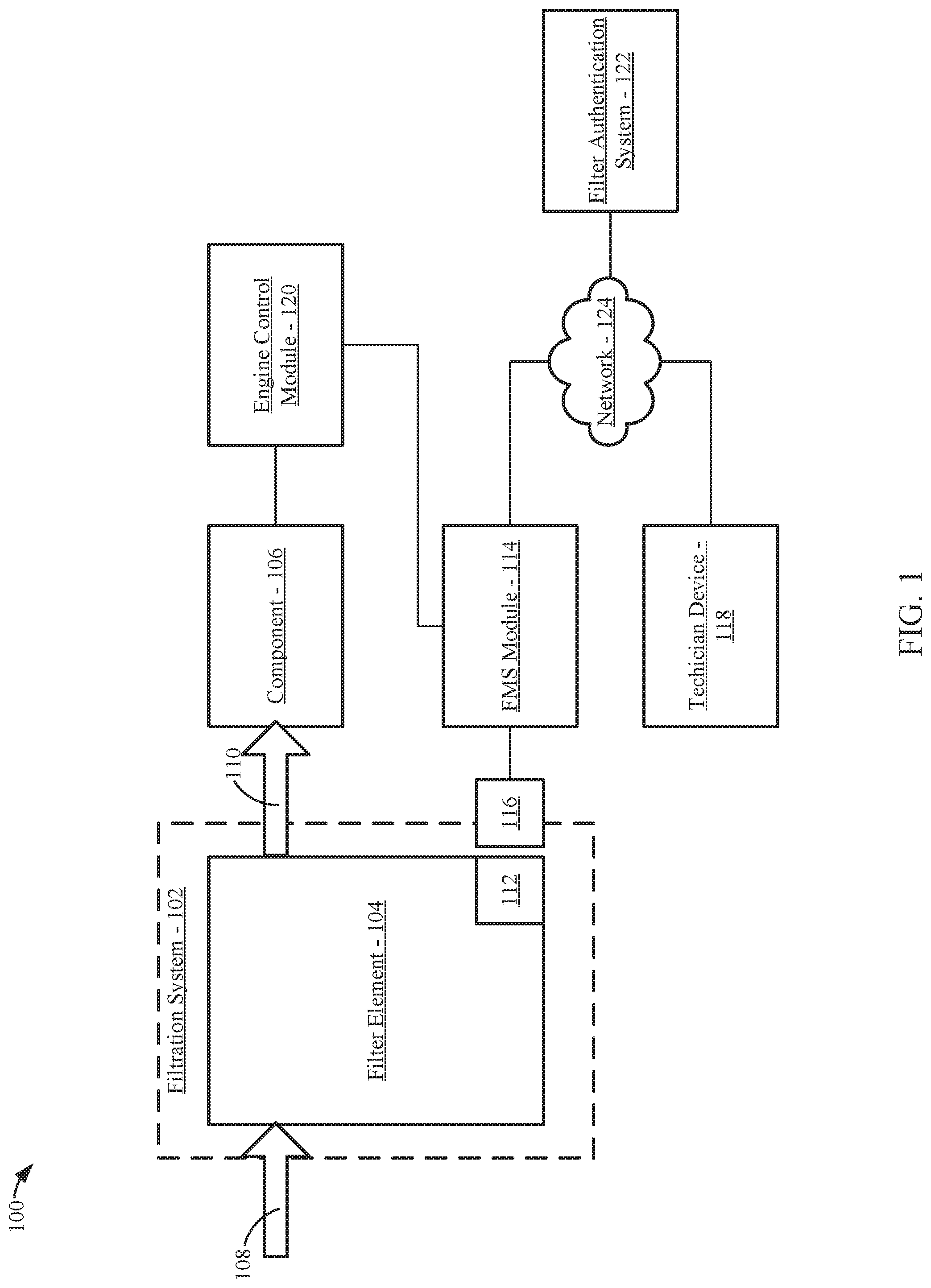
[0016] Referring to FIG. 1, a system 100 is shown according to an example embodiment. As shown in FIG. 1, the system 100 includes a filtration system 102 having a filter element 104 installed in the filtration system 102. The filtration system 102 filters a fluid via the filter element 104 and provides the filtered fluid to a component 106 (e.g., an internal combustion engine, a pump, etc.). For example, the filtration system 102 may be an air filter system that filters intake air for an internal combustion engine (e.g., a diesel internal combustion engine). Accordingly, the filtration system 102 includes a fluid inlet 108 that provides fluid to be filtered to the filter element 104, and a fluid outlet 110 that provides filtered fluid to the downstream component 106. Although shown as including one filtration system 102, it should be understood that system 100 can include any number of filtration systems 102. For example, the system 100 can include any combination of an air filtration system, a fuel filtration system, a lubricant filtration system, a fuel-water separator, a hydraulic fluid filtration system, or the like.
[0017] The filter element 104 generally includes filter media and at least one frame member. In arrangements where the filter element 104 is a cylindrical filter element, the frame member may include at least one of a first endcap and a second endcap that are secured to the filter media. The filter element 104 can be a spin-on filter. As described in further detail below, the filter element 104 is a genuine (i.e., authorized) filter element. As used herein, the terms "genuine" and "authorized" are used to describe filter elements that are approved by the manufacturer and/or operator of the filtration system 102 for use within the filtration system 102. Accordingly, the filter element 104 includes at least one tag 112. The tag 112 may be secured to any component of the filter element 104 (e.g., an endcap, the filter media, the frame, etc.) or the packaging of the filter element 104. In some arrangements, the tag can be embedded in the frame member (e.g., embedded in a top or bottom endcap of the filter element). The tag may be a radio-frequency identification tag ("RFID"), a barcode, a two-dimensional barcode (e.g., a QR code), a cryptographic tag, a holographic tag, or a combination thereof. In some arrangements, the filter element 104 may include two tags 112 of the same format (e.g., each of the tags is an RFID tag) or different format (e.g., one tag is an RFID tag while the other tag is a barcode). The tag 112 is encoded with information that is used to verify the filter element 104 as being a genuine filter element. In some arrangements, the information on the tag 112 is read by a filter monitoring system ("FMS") module 114 via a tag reader 116. In some arrangements, the information on the tag 112 is read by an engine control module ("ECM") 120 via a tag reader 116. In some arrangements, the information on the tag 112 is read by a filter authentication system 122 via a tag reader 116. In other arrangements, the information on the tag 112 is read by a technician device 118 (e.g., a smartphone, a tablet computing device, a PDA, a laptop computer, etc.) at the time the filter element 104 is installed in the filtration system 102. In further arrangements, the information on the tag 112 is read by both the FMS module 114 and the technician device 118.
[0018] In some arrangements, the FMS module 114 is also structured to monitor the status of the filtration system 102 and the installed filter element 104. For example, the FMS module 114 can monitor sensor feedback information relating to the filtration system 102 (e.g., pressure sensors, temperature sensors, fluid quality sensors, etc.) to determine when the filter element 104 requires replacement. Accordingly, the FMS module 114 may be configured in the same manner as set forth in U.S. patent application Ser. No. 14/977,858, entitled "FILTRATION MONITORING SYSTEMS," filed on Dec. 22, 2015, U.S. Provisional Patent Application No. 62/320,030, entitled "SYSTEM AND METHOD FOR CALCULATING REMAINING USEFUL LIFE AND CURRENT FILTER STATUS FOR FUEL AND LUBE FILTERS," filed on Apr. 8, 2016, and/or U.S. Provisional Patent Application No. 62/357,067, entitled "SYSTEM AND METHOD FOR OUTPUTTING FILTER MONITORING SYSTEM INFORMATION VIA TELEMATICS," filed on Jun. 30, 2016, each of which are herein incorporated by reference in their entireties and for all purposes. In arrangements where the component 106 is an internal combustion engine, the FMS module 114 is structured to communicate information with an engine control module 120 (e.g., via a J1939 vehicle bus data link). The engine control module 120 is structured to control the operation of the internal combustion engine. As such, the FMS module 120 can trigger an alert (e.g., a dashboard warning) to an operator of the internal combustion engine via the engine control module 120 if the filter element 104 is determined to be non-authorized and/or non-genuine. In some arrangements, the FMS module 114 is integrated with the ECM 120.
[0019] Both the FMS module 114 and the technician device 118 are configured to provide information gathered from the tag 112 to a filter authentication system 122. The FMS module 114 and the technician device 118 are configured to transmit the information via a network 124 (e.g., the Internet) to the filter authentication system 122. The FMS module 114 and the technician device 118 can communicate data to and from the filter authentication system 122 via the network 124 through any combination of wired data transmission (e.g., Ethernet, USB, etc.) and wireless data transmission (e.g., WiFi, Bluetooth, Zigbee, cellular, etc.) protocols. Accordingly, in some arrangements, the filter authentication system 122 is remote and physically separate from the filtration system 102, the FMS module 114, and/or the component 106 in the sense that data is communicated between the FMS module 114 and the filter authentication system 122 through a network 124 (e.g., an external network, such as the Internet) instead of directly. For example, in arrangements where the filtration system 102 and the FMS module 114 are part of a vehicle powered by an internal combustion engine (i.e., the component 106), the filter authentication system 122 may be part of a remote telematics and diagnostic center (i.e., remote diagnostic system) that is physically separate from the vehicle. In such arrangements, the FMS module 114 can communicate the filter element tag information to the authentication system 122 via a datalink established by a telematics system or a data transceiver (e.g., transceiver 214 discussed below with respect to FIG. 2) over the network 124. The filter authentication system 122 may be affiliated with the manufacturer or operator of the filtration system 102 and/or the filter element 104.
[0020] The filter authentication system 122 verifies that the filter element 104 installed in the filtration system 102 is a genuine or authorized filter element by comparing the received information from the tag 112 with known and verified information. Additionally, the filter authentication system 122 can maintain historical information relating to used filter elements. In some arrangements, the FMS module 114 is configured to locally verify that the filter element 104 installed in the filtration system 102 is a genuine or authorized filter element by comparing the received information from the tag 112 with known and verified information.
[0021] The components of and the operation of the system 100 is described in further detail below with respect to FIGS. 2 through 6.
[0022] Referring to FIG. 2, a block diagram of the FMS module 114 is shown. The FMS module 114 includes a processing circuit 202. The processing circuit 202 includes a processor 204 and memory 206. The processor 204 may be a general-purpose processor, an application specific integrated circuit (ASIC), a programmable logic controller (PLC) ship, one or more field programmable gate arrays (FPGAs), a digital signal processor (DSP), a group of processing components, or other suitable electronic processing components. The memory 206 may include any of RAM, NVRAM, ROM, Flash Memory, hard disk storage, or the like. The processor 204 is structured to execute instructions stored in the memory 206 that cause the processor 204 to control the operation of the FMS module 114. In some arrangements, the memory 206 may also include one or more storage devices (e.g., hard drives, flash drives, computer readable media, etc.) either local or remote from the FMS module 114. The memory 206 can be configured to store look up tables, algorithms, and/or instructions. Such algorithms can include, for example, filter tag verification algorithms.
[0023] The FMS module 114 includes a tag reader input circuit 208, an ECM circuit 210, and a filter verification circuit 212. In some arrangements, each of the tag reader input circuit 208, the ECM circuit 210, and the filter verification circuit 212 are separate from the processing circuit 202 (e.g., as shown in FIG. 2). In other arrangements, the processing circuit 202 includes any or all of the tag reader input circuit 208, the ECM circuit 210, and the filter verification circuit 212.
[0024] The tag reader input circuit 208 is structured to receive information from the tag 112 that is read by the tag reader 116. As described in further detail below, the received information is used to verify that the filter element 104 installed in the filtration system 102 is genuine and authorized.
[0025] The ECM circuit 210 is structured to communicate information to and from the engine control module 120. Accordingly, through the ECM circuit 210, the internal combustion engine can provide a real-time feedback signal relating to engine operating parameters (e.g., speed, temperature, oil pressure, etc.) to the FMS module 114 via the engine control module 120. The real-time feedback of the engine operating parameters may occur via a datalink (e.g., a CANBUS link, a J1939 vehicle bus data link, etc.) with the engine control module 120 via the ECM circuit 210. Additionally, via the ECM circuit 210, the FMS module 114 can send messages to the engine control module 120 (e.g., to trigger a dashboard warning, to give a fault code, to trigger an alarm, to shut off the internal combustion engine, to not start the internal combustion engine, to derate the internal combustion engine, etc.). In some arrangements, the FMS module 114 is part of or integrated with the engine control module 120. In such arrangements, the ECM circuit 210 may be structured control the operation of the internal combustion engine.
[0026] The filter verification circuit 212 is structured to decrypt and/or decode the information received from the tag 112 via the tag reader input circuit 208. The decrypted and/or decoded information is then used to verify that the filter element 104 installed in the filtration system 102 is genuine and authorized (e.g., as described in further detail below with respect to FIG. 6). As discussed above, in some arrangements, the FMS module 114 performs the filter verification locally at the FMS module 114. In other arrangements, the FMS module 114 transmits the tag information to the filter authentication system 122 for filter verification. In such arrangements, the filter verification circuit 212 may be omitted from the FMS module 114.
[0027] The FMS module 114 also includes a data transceiver 214. The data transceiver 214 is structured to facilitate data communication over the network 124 to and from the filter authentication system 122. In some arrangements, the data transceiver 214 includes a wireless data transceiver, such as a WiFi data transceiver, a Bluetooth data transceiver, a cellular data transceiver (e.g., a 2G data transceiver, a 3G data transceiver, a 4G data transceiver, etc.). In some arrangements, the data transceiver 214 transmits data via a telematics module of the system 100.
[0028] Referring to FIG. 3, a block diagram of the filter authentication system 122 is shown. As noted above, in some arrangements, the filter authentication system 122 is remote from the FMS module 114, the filtration system 102, and/or the FMS module 114. The filter authentication system 122 includes a processing circuit 302. The processing circuit 302 includes a processor 304 and memory 306. The processor 304 may be a general-purpose processor, an application specific integrated circuit (ASIC), a programmable logic controller (PLC) ship, one or more field programmable gate arrays (FPGAs), a digital signal processor (DSP), a group of processing components, or other suitable electronic processing components. The memory 306 may include any of RAM, NVRAM, ROM, Flash Memory, hard disk storage, or the like. The processor 304 is structured to execute instructions stored in the memory 306 that cause the processor 304 to control the operation of the filter authentication system 122. In some arrangements, the memory 306 may also include one or more storage devices (e.g., hard drives, flash drives, computer readable media, etc.) either local or remote from the filter authentication system 122. The memory 306 can be configured to store look up tables, algorithms, and/or instructions. Such algorithms can include, for example, filter tag verification algorithms.
[0029] The filter authentication system 122 includes a network interface 308, a filter verification circuit 310, and a filter element database 312. The network interface 308 is structured to facilitate data communication with other devices (e.g., the FMS module 114, the technician device 118, etc.) via the network 124. The filter verification circuit 310 is structured to decrypt and/or decode the information received from the tag 112 (e.g., as received via the FMS module 114 and/or the technician device 118). The decrypted and/or decoded information is then used to verify that the filter element 104 installed in the filtration system 102 is genuine and authorized (e.g., as described in further detail below with respect to FIG. 6). The filter authentication system 122 includes a filter element database 312. In some arrangements, the filter element database 312 is part of the memory 306. The filter element database 312 stores verified filter information that is used by the filter verification circuit 310 to determine whether the filter element 104 installed in the filtration system 102 is genuine and authorized. In some arrangements, the filter element database 312 also includes historic filter usage information (e.g., a record of when specific filter elements were installed in a given filtration system, a record of when non-genuine/non-authorized filter elements were installed in a given filtration system), which may be used to assist with warranty claims involving the system 100.
[0030] Referring to FIG. 4A, a block diagram of the tag 112 is shown according to an example embodiment. The tag 112 of FIG. 4A is an RFID tag. The tag 112 may be an active, semi-active, or passive RFID tag. In some arrangements, the RFID tag 112 may be a cryptographic or holographic RFID tag. Accordingly, the tag 112 includes a control circuit 402, memory 404, a power supply 406, a transceiver 408, and an antenna 410. The control circuit 402 is structured to generally control the operation of the tag 112. When the tag 112 is brought into range of a reader (e.g., tag reader 116), the tag 112 wirelessly communicates a data packet stored in the memory 404 to the reader via the antenna 410 and the transceiver 408. In some arrangements, the tag 112 includes a power supply 406, such as a battery or a capacitor. In other arrangements, the tag 112 receives operating power wirelessly from the reader via the antenna 410.
[0031] The memory 404 is structured to store filter element 104 identification information that uniquely identifies a given filter element 104. Accordingly, the memory 404 may be programmed by the manufacturer of the filter element 104 at the time of manufacturing the filter element 1-4 (e.g., as described below with respect to FIG. 5). In some arrangements, the identification information is a string of digits, symbols and numbers that form a unique identification number of the filter element 104. The unique identification number may be a serial number or another string formed by an algorithm or a plurality of algorithms (e.g., a different algorithm for different parts of a given code) associated with the manufacturer of the filter element 104. The unique identification number of the filter element 104 may include, for example, any combination of a place of manufacture, a date of manufacturer, a time of manufacture, a model number, an application of the filter element 104 (e.g., air, fuel, water, lubricant, etc.), and the like.
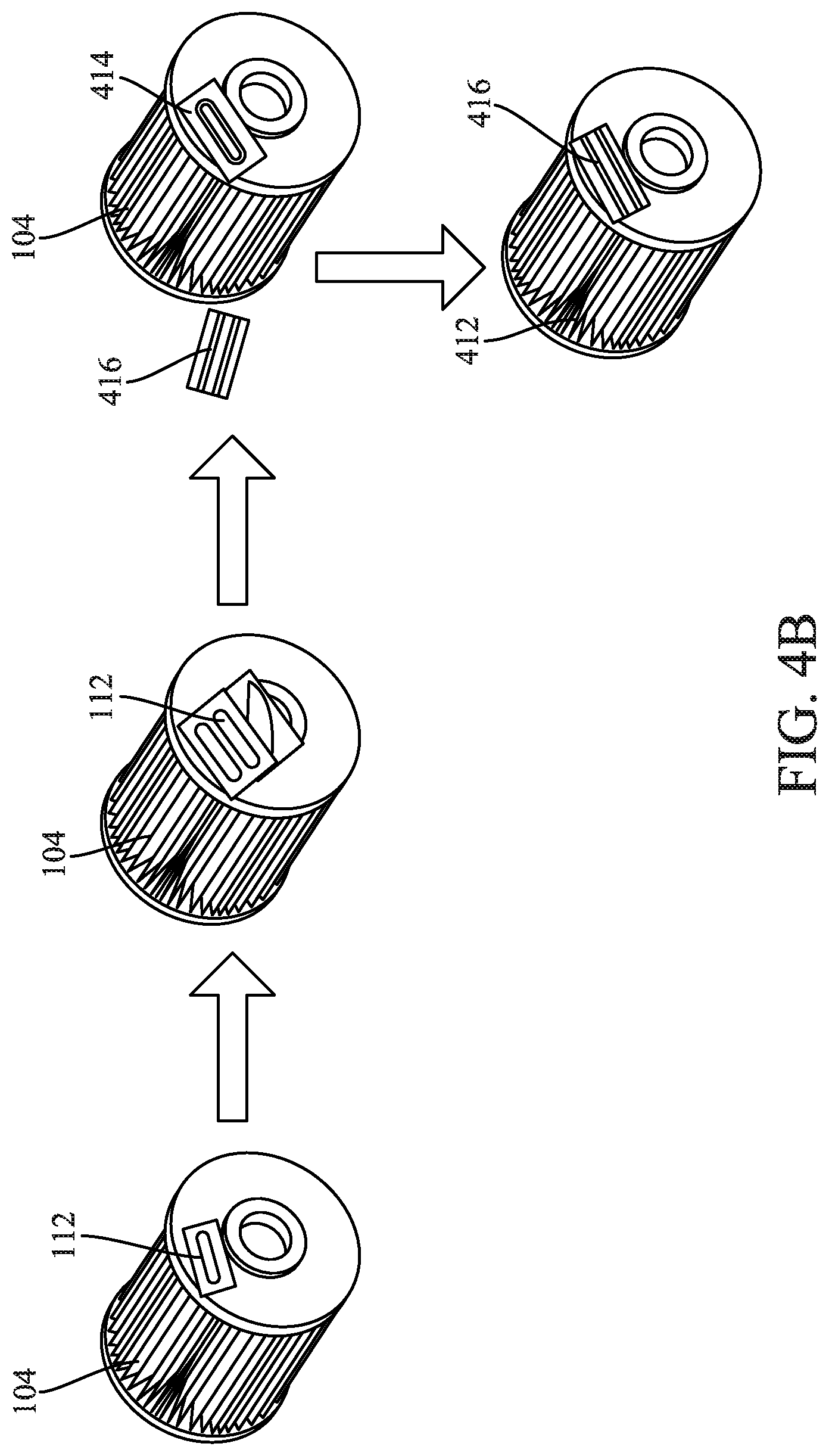
[0032] In some arrangements, the tag 112 is constructed in a manner that prohibits removal and replacement of the tag 112 (e.g., from a first filter element to a second filter element) to prevent reuse or over usage of the tag 112. This may be achieved through the use of a holographic RFID tag that is self-destructive if the tag 112 is removed from the filter element 104. For example, the components of the tag 112 may be placed across different physical layers of the media bearing the tag such that if the tag is removed, the antenna 410 is separated from the rest of the tag 112 thereby rendering the tag 112 inoperable. This concept is demonstrated in FIG. 4B, which shows the stages of attempted moving of the tag 112 from the authorized filter element 104 to a non-authorized filter element 412. As shown in the progression of FIG. 4B, if an individual attempts to remove the tag 112 from the filter element 104, the tag 112 splits into a first part 414 that remains on the filter element 104, and a second part 416 that the individual can stick to the non-authorized filter element 412. However, because the first part 414 contains the antenna 410, the second part 416 when placed on the non-authorized filter element 412 does not function.
[0033] As described above with respect to FIGS. 4A and 4B, the tag 112 is an RFID tag. In alternative arrangements, the tag 112 provides information to the FMS module 114 and/or the technician device 118 via a visible printed code that contains the filter element information or a reference to the filter element information that is remotely stored (e.g., via a barcode, a two-dimensional barcode, a QR code, etc.). The visible printed code may, for example, be scanned with a camera of the technician device 118. In some arrangements, the visible printed code replaces the RFID tag. In other arrangements, an outer surface of the RFID tag includes the visible printed code. The tag 112 may be embedded in a component of the filter element 104 (e.g., embedded in an endcap or frame member), adhered to a component of the filter element 104, printed on a component of the filter element, thermally attached to a component of the filter element, or the like.
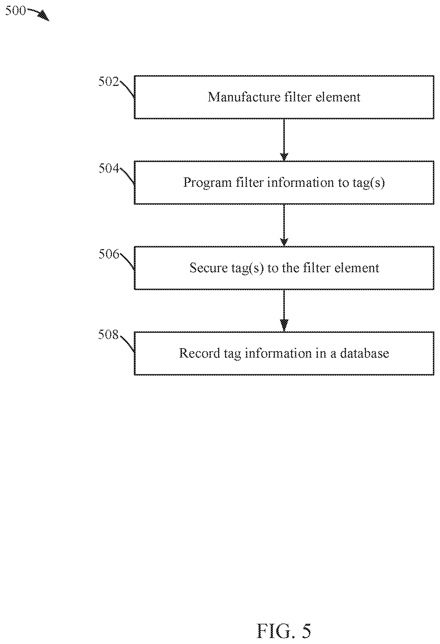
[0034] Referring to FIG. 5, a flow diagram of a method 500 of manufacturing an authorized filter element (e.g., the filter element 104) is shown according to an example embodiment. The method 500 is performed by a manufacturer that is authorized to produce filter elements for the filtration system 102.
[0035] The method 500 begins when the filter element 104 is manufactured at 502. At least one tag 112 is programmed at 504. The tag 112 is programmed with unique information that identifies the manufactured filter element 104. The tag 112 may be an RFID tag, a tag having a visible code (e.g., a barcode, a two-dimensional barcode, a QR code, etc.), or a combination thereof. In some arrangements, multiple tags 112 are created that are associated with the filter element 104. For example, a first tag 112 may be created for the filter element 104, while a second tag 112 may be created for the filter element's packaging. In creating the tag 112, the manufacturer generates a unique identification number associated with the filter element. In arrangements where the tag 112 has memory (e.g., as in an RFID tag), the memory is programmed with the unique identification number. In arrangements where the tag 112 has a visible code, the unique identification number is formatted according to the visible code. In either arrangement, the unique identification number may be encrypted with a private key associated with the manufacturer.
[0036] The at least one tag 112 is secured to the filter element at 506. The tag 112 may be secured to the filter element via an adhesive. In arrangements where multiple tags 112 are associated with the filter element, the other tags are secured at other locations on the filter element 104 or the packaging associated with the filter element 104 (e.g., to the outside of the box housing the filter element 104 during shipment).
[0037] The tag information is recorded in a database (e.g., the filter element database 312) at 508. The tag information, including the unique identification number, is stored in the database for later cross-referencing and verification purposes. In some arrangements, an encryption key used to decode the encrypted data stored in the tag 112 is also stored in the database.
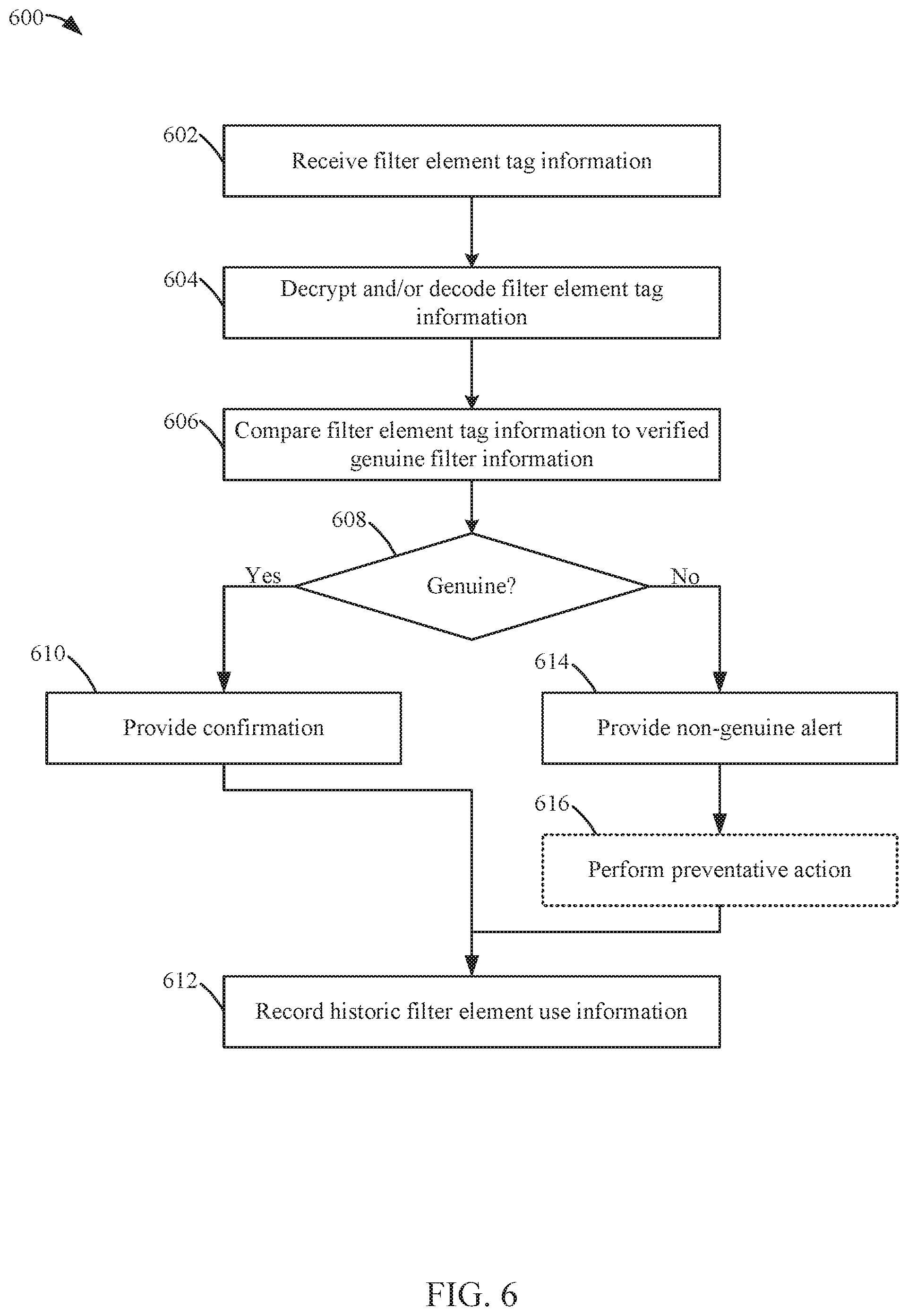
[0038] Referring to FIG. 6, a flow diagram of a method 600 of verifying a filter element as being authentic or genuine is shown according to an example embodiment. In some arrangements, the method 600 is performed at every activation of the filtration system 102 (e.g., at every key-on situation for an internal combustion engine). In some arrangements, the method 600 is performed by the filter authentication system 122. In other arrangements, the method 600 is performed by the FMS module 114. In further arrangements, the method 600 is performed by the technician device 118. For ease of discussion, the following discussion of the method 600 is provided from the perspective of the filter authentication system 122.
[0039] The method 600 begins when filter element tag information is received at 602. The filter authentication system 122 receives information gathered from the tag 112 from either the FMS module 114 or the technician device 118 via the network 124. In arrangements where the filter element tag information is received from the FMS module 114, the filter element 104 is installed in the filtration system 102 prior to receiving the filter element tag information at 602. In arrangements where the filter element tag information is received from the technician device 118, the filter element tag information may be received prior to the filter element 104 being installed in the filtration system 102 (e.g., by the technician scanning the box the filter element 104 was packaged in or the tag 112 on the filter element 104 prior to installing the filter element 102 in the filtration system 104) or after the filter element 104 is installed in the filtration system 102. The filter element tag information relates to identification information that uniquely identifies the filter element 104 installed in the filtration system 102 (e.g., a unique identification number associated with the filter element 104). In some arrangements, the filter element tag information is encrypted. The filter element tag information is decrypted and/or decoded at 604. In arrangements where the received filter element tag information is encrypted, the filter element tag information is decrypted (e.g., with an encryption key provided by the manufacturer of the filter element 104). In some arrangements, the filter element tag information is received along with system 100 information, such as equipment type, vehicle type, model numbers, internal combustion engine information, filter life span, miles of usage, filter restriction, geographical information of the system, and the like.
[0040] The filter element tag information is compared to verified genuine filter element information at 606. The filter authentication system 122 compares the filter element tag information with verified genuine filter element information stored in the filter element database 312. The verified genuine filter element information may relate to a filter identification number or an algorithm that verifies the received filter element tag information. The algorithm may include comparing a number of bits contained in the received filter element identification code, performing mathematical equations on the received filter element identification code, and the like. Based on the comparison at 606, the filter authentication system 122 determines whether the filter element installed in the filtration system is genuine at 608. In some arrangements, a filter element 104 may be determined to be "non-genuine" if the filter element 104 has been used in multiple different filtration systems 102 thereby preventing reuse of an originally genuine filter element 104.
[0041] If the filter element is determined to be genuine, a confirmation is provided at 610. The filter authentication system 122 can transmit a confirmation to the FMS module 114 and/or to the technician device 118 to alert the operator of the system 100 (and/or the technician installing the filter element 104) that the filter element is genuine.
[0042] If the filter element is not determined to be genuine, a non-genuine alert is provided at 614. The filter authentication system 122 can transmit a non-genuine alert to the FMS module 114 and/or to the technician device 118 to alert the operator of the system 100 (and/or the technician installing the filter element 104) that the filter element 104 is not genuine. In arrangements where the alert is transmitted to the FMS module 114, the FMS module 114 can transmit the received non-genuine alert to the engine control module 120, which can in turn trigger a warning to an operator of the system 100 (e.g., a dashboard light, an alarm, etc.). In some arrangements, preventative action is performed at 616. The preventative action helps reduce the risk of damage to the downstream component 106 (e.g., to the internal combustion engine). The filter authentication system 122 can transmit instructions to the FMS module 114 to activate the preventative action. The preventative action may be to prevent the component 106 from activating (e.g., prevent the internal combustion engine from turning on), shut the component 106 down (e.g., turn the internal combustion engine off), restrict the operation of the component 106 (e.g., derate the internal combustion engine), or the like.
[0043] Historic filter element use information is recorded at 612. The filter authentication system 122 records information concerning the installed filter element 104 in the filter element database 312. The information concerning the installed filter element 104 is associated with the filtration system 102. For example, the database may be updated to indicate the date that the filter element 104 was installed and whether the filter element 104 is genuine. The information in the filter element database 312 may be used, for example, in assessing future warranty claims relating to the filtration system 102 and/or to the component 106.
[0044] In some arrangements, the method 600 is repeated for each tag 112 scanned that is associated with the filter element 104. For example, in some arrangements, the filter authentications system 122 receives information concerning two tags 112 associated with the filter element 104: a first tag 112 scanned by the technician device 118, and a second tag 112 scanned by FMS module 114 via the tag reader 116. The first tag 112 may be positioned on the packaging associated with the filter element 104, while the second tag 112 may be affixed to the filter element 104. In such arrangements, steps 602-606 may be performed twice in parallel before determining whether the filter element 104 is genuine. If at least one of the tags 112 proves to be inconsistent with the verified tag information, the filter element 104 may be determined to be non-genuine at 608. Accordingly, in such arrangements, the filter element 104 is authenticated through a two-factor authentication process.
[0045] Although described as being performed by the filter authentication system 122, it should be understood that the FMS module 114 can also perform the method 600 in the same manner as described above. In such arrangements, the FMS module receives the filter element tag information from the tag reader 116 at 602. The remaining steps of the method 600 are substantially the same as described from the perspective of the filter authentication system 122.
[0046] Although described as being performed by the filter authentication system 122, it should be understood that the technician device 118 can also perform the method 600 in the same manner as described above. In such arrangements, the technician device 118 receives the filter element tag information by scanning the tag 112 (e.g., via an RFID antenna, via a camera, via a barcode scanner, etc.) at 602. The remaining steps of the method 600 are substantially the same as described from the perspective of the filter authentication system 122.
[0047] It should be noted that any use of the term "example" herein to describe various embodiments is intended to indicate that such embodiments are possible examples, representations, and/or illustrations of possible embodiments (and such term is not intended to connote that such embodiments are necessarily extraordinary or superlative examples).
[0048] It is important to note that the construction and arrangement of the various example embodiments are illustrative only. Although only a few embodiments have been described in detail in this disclosure, those skilled in the art who review this disclosure will readily appreciate that many modifications are possible (e.g., variations in sizes, dimensions, structures, shapes and proportions of the various elements, values of parameters, mounting arrangements, use of materials, colors, orientations, etc.) without materially departing from the novel teachings and advantages of the subject matter described herein. For example, elements shown as integrally formed may be constructed of multiple parts or elements, the position of elements may be reversed or otherwise varied, and the nature or number of discrete elements or positions may be altered or varied. The order or sequence of any process or method steps may be varied or re-sequenced according to alternative embodiments. Additionally, features from particular embodiments may be combined with features from other embodiments as would be understood by one of ordinary skill in the art. Other substitutions, modifications, changes and omissions may also be made in the design, operating conditions and arrangement of the various example embodiments without departing from the scope of the present invention.
[0049] Additionally, the format and symbols employed are provided to explain the logical steps of the schematic diagrams and are understood not to limit the scope of the methods illustrated by the diagrams. Although various arrow types and line types may be employed in the schematic diagrams, they are understood not to limit the scope of the corresponding methods. Indeed, some arrows or other connectors may be used to indicate only the logical flow of a method. For instance, an arrow may indicate a waiting or monitoring period of unspecified duration between enumerated steps of a depicted method. Additionally, the order in which a particular method occurs may or may not strictly adhere to the order of the corresponding steps shown. It will also be noted that each block of the block diagrams and/or flowchart diagrams, and combinations of blocks in the block diagrams and/or flowchart diagrams, can be implemented by special purpose hardware-based systems that perform the specified functions or acts, or combinations of special purpose hardware and program code.
[0050] Some of the functional units described in this specification have been labeled as circuits, in order to more particularly emphasize their implementation independence. For example, a circuit may be implemented as a hardware circuit comprising custom very-large-scale integration (VLSI) circuits or gate arrays, off-the-shelf semiconductors such as logic chips, transistors, or other discrete components. A circuit may also be implemented in programmable hardware devices such as field programmable gate arrays, programmable array logic, programmable logic devices or the like.
[0051] As mentioned above, circuits may also be implemented in machine-readable medium for execution by various types of processors, such as the processor of the FMS module 114 of FIG. 1. An identified circuit of executable code may, for instance, comprise one or more physical or logical blocks of computer instructions, which may, for instance, be organized as an object, procedure, or function. Nevertheless, the executables of an identified circuit need not be physically located together, but may comprise disparate instructions stored in different locations which, when joined logically together, comprise the circuit and achieve the stated purpose for the circuit. Indeed, a circuit of computer readable program code may be a single instruction, or many instructions, and may even be distributed over several different code segments, among different programs, and across several memory devices. Similarly, operational data may be identified and illustrated herein within circuits, and may be embodied in any suitable form and organized within any suitable type of data structure. The operational data may be collected as a single data set, or may be distributed over different locations including over different storage devices, and may exist, at least partially, merely as electronic signals on a system or network.
[0052] The computer readable medium (also referred to herein as machine-readable media or machine-readable content) may be a tangible computer readable storage medium storing computer readable program code. The computer readable storage medium may be, for example, but not limited to, an electronic, magnetic, optical, electromagnetic, infrared, holographic, micromechanical, or semiconductor system, apparatus, or device, or any suitable combination of the foregoing. As alluded to above, examples of the computer readable storage medium may include but are not limited to a portable computer diskette, a hard disk, a random access memory (RAM), a read-only memory (ROM), an erasable programmable read-only memory (EPROM or Flash memory), a portable compact disc read-only memory (CD-ROM), a digital versatile disc (DVD), an optical storage device, a magnetic storage device, a holographic storage medium, a micromechanical storage device, or any suitable combination of the foregoing. In the context of this document, a computer readable storage medium may be any tangible medium that can contain, and/or store computer readable program code for use by and/or in connection with an instruction execution system, apparatus, or device.
[0053] The computer readable medium may also be a computer readable signal medium. A computer readable signal medium may include a propagated data signal with computer readable program code embodied therein, for example, in baseband or as part of a carrier wave. Such a propagated signal may take any of a variety of forms, including, but not limited to, electrical, electro-magnetic, magnetic, optical, or any suitable combination thereof. A computer readable signal medium may be any computer readable medium that is not a computer readable storage medium and that can communicate, propagate, or transport computer readable program code for use by or in connection with an instruction execution system, apparatus, or device. As also alluded to above, computer readable program code embodied on a computer readable signal medium may be transmitted using any appropriate medium, including but not limited to wireless, wireline, optical fiber cable, Radio Frequency (RF), or the like, or any suitable combination of the foregoing. In one embodiment, the computer readable medium may comprise a combination of one or more computer readable storage mediums and one or more computer readable signal mediums. For example, computer readable program code may be both propagated as an electro-magnetic signal through a fiber optic cable for execution by a processor and stored on RAM storage device for execution by the processor.
[0054] Computer readable program code for carrying out operations for aspects of the present invention may be written in any combination of one or more programming languages, including an object oriented programming language such as Java, Smalltalk, C++ or the like and conventional procedural programming languages, such as the "C" programming language or similar programming languages. The computer readable program code may execute entirely on a computer, partly on the computer, as a stand-alone computer-readable package, partly on the computer and partly on a remote computer or entirely on the remote computer or server. In the latter scenario, the remote computer may be connected to the user's computer through any type of network, including a local area network (LAN) or a wide area network (WAN), or the connection may be made to an external computer (for example, through the Internet using an Internet Service Provider). The program code may also be stored in a computer readable medium that can direct a computer, other programmable data processing apparatus, or other devices to function in a particular manner, such that the instructions stored in the computer readable medium produce an article of manufacture including instructions which implement the function/act specified in the schematic flowchart diagrams and/or schematic block diagrams block or blocks.
[0055] Accordingly, the present disclosure may be embodied in other specific forms without departing from its spirit or essential characteristics. The described embodiments are to be considered in all respects only as illustrative and not restrictive. The scope of the disclosure is, therefore, indicated by the appended claims rather than by the foregoing description. All changes which come within the meaning and range of equivalency of the claims are to be embraced within their scope.
* * * * *
D00000
D00001
D00002
D00003
D00004
D00005
D00006
XML
uspto.report is an independent third-party trademark research tool that is not affiliated, endorsed, or sponsored by the United States Patent and Trademark Office (USPTO) or any other governmental organization. The information provided by uspto.report is based on publicly available data at the time of writing and is intended for informational purposes only.
While we strive to provide accurate and up-to-date information, we do not guarantee the accuracy, completeness, reliability, or suitability of the information displayed on this site. The use of this site is at your own risk. Any reliance you place on such information is therefore strictly at your own risk.
All official trademark data, including owner information, should be verified by visiting the official USPTO website at www.uspto.gov. This site is not intended to replace professional legal advice and should not be used as a substitute for consulting with a legal professional who is knowledgeable about trademark law.