Sensory Stimulating Apparatus and Method(s) of Using the Same
Newton; Charles ; et al.
U.S. patent application number 16/504169 was filed with the patent office on 2020-01-09 for sensory stimulating apparatus and method(s) of using the same. The applicant listed for this patent is Charles Newton, Mary S. Newton. Invention is credited to Charles Newton, Mary S. Newton.
| Application Number | 20200009468 16/504169 |
| Document ID | / |
| Family ID | 69101358 |
| Filed Date | 2020-01-09 |


| United States Patent Application | 20200009468 |
| Kind Code | A1 |
| Newton; Charles ; et al. | January 9, 2020 |
Sensory Stimulating Apparatus and Method(s) of Using the Same
Abstract
A sensory stimulating apparatus and methods of use, comprising an elongated connector having opposing first and second ends, said first and second opposing ends being respectively operably coupled to a first ratchet having a first hollow cavity and to one of a second ratchet having a second hollow cavity, and a solid disk. The first ratchet has teeth, a click that engages with the teeth, such that the click easily slides over the teeth in an unrestricted direction of rotation and will catch or lock on the first tooth it encounters in a restricted direction of rotation. A first soft ball rotatably coupled within the hollow cavity of the first ratchet, such that rotation of the elongated connector in the restricted direction causes the ratchet to rotate. The first soft ball moves the first ratchet when rotated in the unrestricted direction, producing a vibration.
| Inventors: | Newton; Charles; (Selkirk, NY) ; Newton; Mary S.; (Selkirk, NY) | ||||||||||
| Applicant: |
|
||||||||||
|---|---|---|---|---|---|---|---|---|---|---|---|
| Family ID: | 69101358 | ||||||||||
| Appl. No.: | 16/504169 | ||||||||||
| Filed: | July 5, 2019 |
Related U.S. Patent Documents
| Application Number | Filing Date | Patent Number | ||
|---|---|---|---|---|
| 62694964 | Jul 6, 2018 | |||
| Current U.S. Class: | 1/1 |
| Current CPC Class: | A63H 31/08 20130101; A63H 33/00 20130101 |
| International Class: | A63H 31/08 20060101 A63H031/08; A63H 33/00 20060101 A63H033/00 |
Claims
1. An apparatus that provides sensory stimulation, comprising an elongated connector having opposing first and second ends, wherein the first opposing end is operably coupled to a first ratchet having a first hollow cavity, and wherein the second opposing end is operably coupled to one of a second ratchet having a second hollow cavity, or a solid shape, wherein the first ratchet has teeth, a click that engages with the teeth, an unrestricted direction of rotation such that the click easily slides over the teeth and a restricted direction of rotation such that the click will catch on the first tooth it encounters locking against the tooth and preventing any further rotation in that direction, wherein a first soft ball having a diameter that is slightly larger than a diameter of the hollow cavity of the first ratchet is inserted into the first hollow cavity of the first ratchet, such that rotation of the elongated connector in the restricted direction around the first ball causes the ratchet to rotate due to frictional forces that rotatably couple the first ball and the first ratchet, and wherein the first soft ball moves the first ratchet when rotated in the unrestricted direction, producing a vibration.
2. The apparatus of claim 1, wherein the elongated connector is treated with an electrophoretic lacquer.
3. The apparatus of claim 1, wherein the first ball is releasably operably coupled with the first ratchet.
4. The apparatus of claim 1, wherein the second opposing end of the elongated connector has a solid shape in the form of a solid disk, and wherein the superior and inferior surfaces of the solid disk have concave indentations.
5. The apparatus of claim 1, wherein the second opposing end of the elongated connector has a solid shape in the form of a solid disk shape, wherein the superior and inferior surfaces have convex surfaces.
6. The apparatus of claim 4, wherein the solid disk is operably coupled along a central axis by a rod, allowing it to swivel freely.
7. The apparatus of claim 5, wherein the disk is operably coupled along a central axis by a rod, allowing it to swivel freely.
8. The apparatus of claim 4, wherein the solid disk is operably coupled along a central axis by a rod, allowing it to rotate freely.
9. The apparatus of claim 5, wherein the disk is operably coupled along a central axis by a rod, allowing it to rotate freely.
10. The apparatus of claim 4, wherein the diameter of the concave indentations is approximately the diameter of a human thumb.
11. The apparatus of claim 1, wherein the first ball has a 9 mm diameter, and the first ratchet is an 8 mm ratchet.
12. The apparatus of claim 1, wherein the first ratchet does not have a square drive.
13. The apparatus of claim 1, wherein a second ratchet is operably coupled to the second opposing end of the elongated connector, and a second soft ball is operably coupled within a second hollow cavity of the second ratchet.
14. The apparatus of claim 13, wherein the second ratchet does not have a square drive.
15. The apparatus of claim 1, comprising a switch, causing the click of the first ratchet to tighten or loosen in and out of contact range of a gear of the ratchet.
16. The apparatus of claim 1, comprising first and second switches, wherein the first switch causes the click of the first ratchet to tighten or loosen in and out of contact range of a gear of the first ratchet, and a second switch, wherein the second switch causes a click of the second ratchet to tighten or loosen in and out of contact range of a gear of the second ratchet.
17. The apparatus of claim 1, wherein the soft ball is made of material from the group consisting of a plastic bead or a silicon ball.
18. The apparatus of claim 1, wherein the first ratchet drives the click instead of a square drive when moving the elongated connector in the unrestricted direction of rotation (23) while holding the soft ball (27, 37) motionless.
19. The apparatus of claim 13, wherein the second ratchet drives the click instead of a square drive when moving the elongated connector in the unrestricted direction of rotation (23) while holding the soft ball (27, 37) motionless.
20. A method of using a sensory stimulator, comprising: providing the sensory stimulator of claim 1; rotating the soft ball with one or more fingers; moving the ratchet and producing a vibration; and repeating the movement or reversing the movement, as desired.
21. A method of using a sensory stimulator, comprising: providing the sensory stimulator of claim 1, and holding the soft ball motionless with one or more fingers; moving the elongated connector of the sensory stimulator; moving the ratchet and producing a vibration; and repeating the movement or reversing the movement, as desired.
22. A method of using a sensory stimulator, comprising: providing the sensory stimulator of claim 1; and rolling the soft ball between thumb and finger without moving the ratchet.
Description
I. FIELD OF THE INVENTION
[0001] The present invention relates generally to devices used to provide sensory stimulation, and methods of using the same.
II. BACKGROUND
[0002] Stress management is an important part of ensuring a productive and functional environment in the office and in the school. In particular, office toys and other management tools for providing manual manipulation of an object and better focus in a learning or office environment are well known in the art. Therefore, there exists a need for an apparatus for providing sensory stimulation, and methods of using the same.
III. SUMMARY OF THE INVENTION
[0003] A first aspect of the present invention provides an apparatus for providing sensory stimulation. The apparatus has an elongated connector having opposing first and second ends. The first opposing end is operably coupled to a first ratchet having a first hollow cavity. The second opposing end is operably coupled to one of a second ratchet having a second hollow cavity, and a solid shape. The first ratchet has teeth, a click that engages with the teeth, an unrestricted direction of rotation such that the click easily slides over the teeth and a restricted direction of rotation such that the click will catch on the first tooth it encounters locking against the tooth and preventing any further rotation in that direction. There is a first soft ball having a diameter that is slightly larger than a diameter of the hollow cavity of the first ratchet is inserted into the first hollow cavity of the first ratchet, such that rotation of the elongated connector causes the ratchet to rotate due to frictional forces that rotatably couple the first ball and the first ratchet. The first soft ball moves the first ratchet when rotated in the unrestricted direction, producing a vibration.
[0004] A second aspect of the present invention provides a method of using a sensory stimulator, comprising: providing a sensory stimulator; rotating the soft ball with one or more fingers; moving the ratchet and producing a vibration, and repeating the movement or reversing the movement, as desired.
[0005] A third aspect of the present invention provides a method of using a sensory stimulator, comprising: providing a sensory stimulator, and holding the soft ball motionless with one or more fingers; moving the elongated connector of the sensory stimulator; moving the ratchet and producing a vibration; and repeating the movement or reversing the movement, as desired.
[0006] A fourth aspect to the present invention provides a method of using a sensory stimulator, comprising: providing a sensory stimulator; and rolling the soft ball between thumb and finger without moving the ratchet
BRIEF DESCRIPTION OF THE DRAWINGS
[0007] The features of the invention are set forth in the appended claims. The invention itself, however, will be best understood by reference to the following detailed description of an illustrative embodiment when read in conjunction with the accompanying drawings, wherein:
[0008] FIG. 1A. depicts a front view of an apparatus 1 for providing sensory stimulation, in accordance with embodiments of the present invention; and
[0009] FIG. 1B depicts a front view of the apparatus 1 for providing sensory stimulation, in accordance with embodiments of the present invention; and
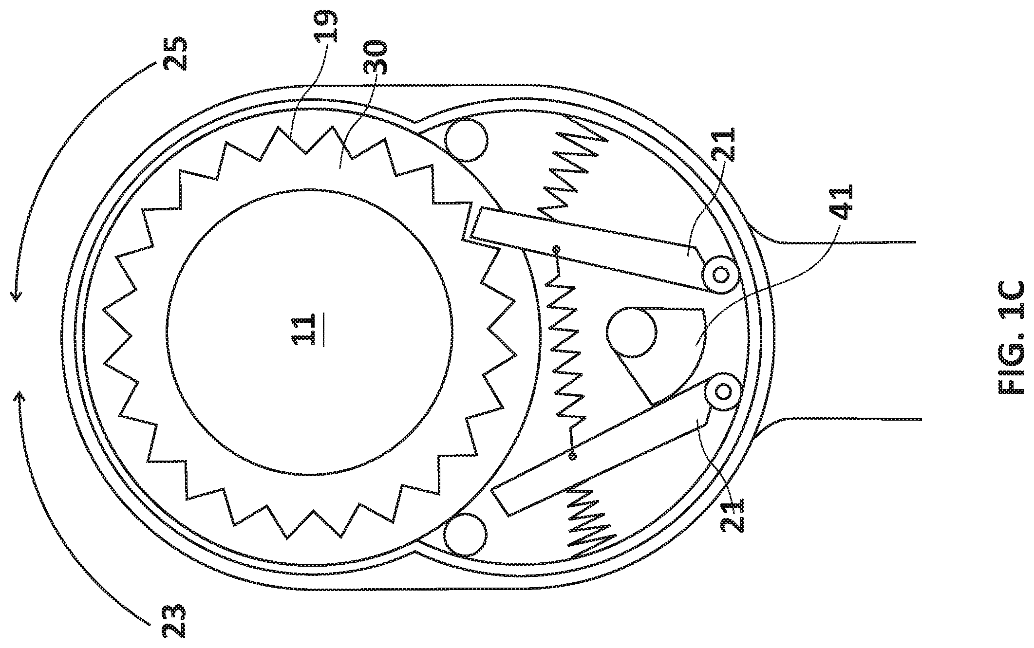
[0010] FIG. 1C depicts a cross sectional view of a first ratchet of the apparatus 1 for providing sensory stimulation, taken along the lines 1C-1C, in accordance with embodiments of the present invention; and
[0011] FIG. 1D depicts a front view of the apparatus 1 for providing sensory stimulation with the soft ball removed, in accordance with embodiments of the present invention;
[0012] FIG. 2 depicts a side view of the apparatus 1 for providing sensory stimulation, in accordance with embodiments of the present invention;
[0013] FIG. 3 depicts a front view of the apparatus 1 for providing sensory stimulation, in accordance with embodiments of the present invention;
[0014] FIG. 4 depicts a front view of the apparatus 1 for providing sensory stimulation, in accordance with embodiments of the present invention; and
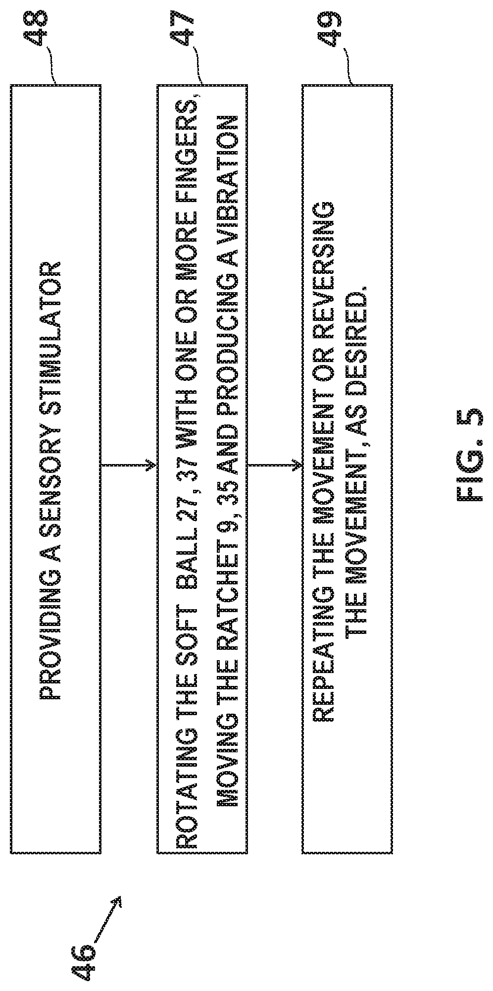
[0015] FIG. 5 depicts a flow chart of a method of using the apparatus 1 depicted in FIGS. 1A-D, and 2-4, in accordance with embodiments of the present invention; and
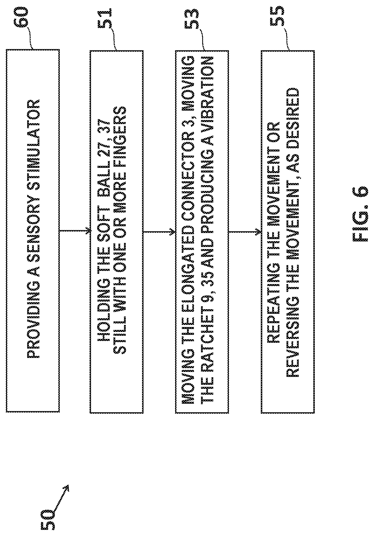
[0016] FIG. 6 depicts a flow chart of a method of using the apparatus 1 depicted in FIGS. 1A-D, and 2-4, in accordance with embodiments of the present invention.
DETAILED DESCRIPTION OF THE EMBODIMENTS OF THE INVENTION
Definitions
[0017] Hereinafter, unless otherwise defined, the term "providing sensory stimulation" for a mammal, e.g., a person, means providing any act that relieves stress in a mammal, e.g., a person, said act generating between 4 and 24 clicks per second when a first ratchet 9 is rotated by the mammal or a human hand of the person in the unrestricted direction 23.
[0018] As used herein, unless otherwise defined, the singular forms "a", "an", and "the" include plural references unless the context clearly dictates otherwise. Thus, for example, reference to "a tooth" includes a plurality of such teeth, and so forth.
[0019] As used herein, unless otherwise defined, the term "operably coupled" is defined as operably connected in any desired form, for example, mechanically, electronically, digitally, directly, by software, by hardware and the like. Throughout this application, the term "operably coupled" is defined as a connection of one or more components in a manner that allows them to function together. For example, networked computers are operably coupled through their network adapters. A display is operably coupled to a processor when the processor is able to cause the display to display an image. When components communicate through a wireless connection, they are considered to be operably coupled.
[0020] As used herein, unless otherwise defined, the term "releasable operable coupling" or "releasably operably coupled" or "releasably operably joined" is defined as forming or braking or cleaving or severing of a mechanical coupling between ball 27 and the first ratchet 9, as shown in FIG. 1D and discussed in associated text, herein, in addition. The ball 27 and the first ratchet 9 are capable of forming, braking, cleaving, or severing a connection in a manner that allows them to function together.
[0021] As used herein, unless otherwise defined, the term "rotatably coupled" means operably coupling the disk shape 17 to the opposing end of the elongated connector 3 by means of a rod 33 along the longitudinal axis of the elongated connector 3, allowing the disk shape 17 to rotate 360 degrees about its central axis, as shown in FIG. 4.
[0022] FIG. 1A and FIG. 1B depict a front view of the apparatus 1 for providing sensory stimulation, in accordance with embodiments of the present invention. The apparatus 1 has an elongated connector 3 having opposing first and second ends 5, 7. The first opposing end 5 is operably coupled to a first ratchet 9 having a first hollow cavity 11. The second opposing end 7 is operably coupled to either a second ratchet 35 having a second hollow cavity 39, or a solid shape 17.
[0023] FIG. 1C shows a cross sectional view of the first ratchet 9 taken along the lines 1C-1C. The first ratchet 9 has teeth 19, a click 21 that engages with the teeth 19, an unrestricted direction of rotation 23 such that the click easily slides over the teeth with a spring forcing the click 21 into moving over the teeth 21 and between the teeth, producing an audible or feelable `click` as the click 21 engages with the teeth 19, and a restricted direction of rotation 25 such that the click will catch on the first tooth it encounters locking against the tooth and preventing any further rotation in that direction. There is a first soft ball 27 having a diameter that is slightly larger than a diameter of the hollow cavity 11 of the first ratchet 9 that is inserted (as shown in FIG. 1D) into the first hollow cavity 9 of the first ratchet 11, such that rotation of the elongated connector 3 in the restricted direction 25 around the first soft ball 27 causes the apparatus to rotate due to frictional forces that rotatably couple the first ball 27 and the first ratchet 9. The first soft ball 27 moves the first ratchet 9 when rotated in the unrestricted direction, producing a vibration.
[0024] In an embodiment, the elongated connector 3 is treated with an electrophoretic lacquer.
[0025] In an embodiment, the first ball 27 is releasably operably coupled with the first ratchet 9.
[0026] FIG. 2 depicts a side view of the apparatus 1 for providing sensory stimulation, in accordance with embodiments of the present invention. In an embodiment, the second opposing end 7 of the elongated connector 3 has a solid disk shape 17 and the superior and inferior surfaces 29, 31 of the disk shape 17 have concave indentations.
[0027] In an embodiment, the first opposing end 5 of the elongated connector 3 has a solid disk shape 17 and the superior and inferior 29, 31 surfaces are convex surfaces.
[0028] In an embodiment, the disk shape 17 is may be rotatably coupled to the opposing end of the elongated connector 3 by means of a rod 33 along the longitudinal axis of the elongated connector 3, allowing the disk shape 17 to rotate 360 degrees about its central axis, as shown in FIG. 4. In an embodiment, the disk shape 17 is able to swivel freely about its central axis.
[0029] In an embodiment, the diameter of the concave indentations of the solid shape 17 is approximately the diameter of a human thumb.
[0030] In an embodiment, the first ball 27 has a 9 mm diameter, and the first ratchet 9 is an 8 mm ratchet.
[0031] In an embodiment, the number of teeth 19 on the first ratchet 9 are sufficient in number to result in between 4 and 24 clicks per second when the first ratchet 9 is rotated in the unrestricted direction 23 by a human hand.
[0032] FIG. 3 depicts a front view of the apparatus 1 for providing a sensory stimulation, in accordance with embodiments of the present invention. In an embodiment, a second ratchet 35 is operably coupled to the second opposing end 7 of the elongated connector 37, and a second soft ball 27 is operably coupled within a second hollow cavity 39 of the second ratchet 35.
[0033] In an embodiment, the first ratchet 9 does not have a square drive. In an embodiment, the second ratchet 35 does not have a square drive.
[0034] In an embodiment, the soft ball 27 is made from material selected from the group consisting of a plastic bead or a silicone ball.
[0035] In an embodiment, the first ratchet 9 drives the click 21 instead of a square drive of a conventional ratchet driver when moving the elongated connector in the unrestricted direction of rotation 23 while holding the soft ball 27, 37 motionless.
[0036] In an embodiment, the second ratchet 35 drives the click 21 instead of the square drive of a conventional ratchet driver when moving the elongated connector in the unrestricted direction of rotation 23 while holding the soft ball 27, 37 motionless.
[0037] In an embodiment, a switch 41 causes the click 21 of the first ratchet to tighten or loosen in and out of contact range of the teeth 19 of the ratchet.
[0038] In an embodiment, there are first and second switches 43, 45, wherein the first switch 43 causes the click 21 of the first ratchet 9 to tighten or loosen in and out of contact range of a gear 30 of the first ratchet 9, and a second switch 45, wherein the second switch 45 causes a click 21 of the second ratchet 35 to tighten or loosen in and out of contact range of a gear 30 of the second ratchet.
[0039] FIG. 4 depicts a front view of the apparatus 1 for providing sensory stimulation, in accordance with disk shapes 17 on the first and second opposing ends 5, 7.
[0040] FIG. 5 depicts a flow chart 46 of a method 46 of using the apparatus 1 for providing sensory stimulation, in accordance with embodiments of the present invention. In a step 48 of the method 46, apparatus 1, for providing sensory stimulation is provided. A second step 47 of the method 46 comprises rotating the soft ball 27, 37 with one or more fingers, moving the ratchet 9, 35 and producing a vibration. A third step 49 of the method 46 comprises repeating the movement or reversing the movement, as desired.
[0041] FIG. 6 depicts a flow chart of a method 50 of using the apparatus 1 for providing sensory stimulation, in accordance with embodiments of the present invention. In a first step 60 of the method 50, apparatus 1, for providing sensory stimulation is provided. A second step 51 of the method 50 comprises holding the soft ball 27, 37 motionless with one or more fingers. A third step 53 of the method 50 comprises moving the elongated connector 3 of the sensory stimulator, moving the ratchet and producing a vibration 9, 35. A fourth step 55 of the method 50 comprises repeating the movement or reversing the movement, as desired.
[0042] In executing step 51 and 52 of method 50, moving the elongated connector in the unrestricted direction of rotation 23 while holding the soft ball 27, 37 motionless drives the click over the teeth in contrast to a typical ratchet wrench that drives a square driver instead of the click.
[0043] In an embodiment, the soft ball 27 can be rolled between the thumb and a finger of a person independently of the ratchet.
[0044] While exemplary embodiments have been specifically disclosed, it should be understood that the practice of this invention is not limited to those embodiments. Modifications and variations falling within the spirit of the invention will occur to those skilled in the art. Therefore, it is not intended that the scope of the invention be determined by the disclosed exemplary embodiments, but rather should be determined by the breadth of the appended claims.
* * * * *
D00000
D00001
D00002
D00003
D00004
D00005
D00006
D00007
D00008
XML
uspto.report is an independent third-party trademark research tool that is not affiliated, endorsed, or sponsored by the United States Patent and Trademark Office (USPTO) or any other governmental organization. The information provided by uspto.report is based on publicly available data at the time of writing and is intended for informational purposes only.
While we strive to provide accurate and up-to-date information, we do not guarantee the accuracy, completeness, reliability, or suitability of the information displayed on this site. The use of this site is at your own risk. Any reliance you place on such information is therefore strictly at your own risk.
All official trademark data, including owner information, should be verified by visiting the official USPTO website at www.uspto.gov. This site is not intended to replace professional legal advice and should not be used as a substitute for consulting with a legal professional who is knowledgeable about trademark law.