Integrated Grounding Electrodes For Eletrocautery Vessel Harvester
Fujii; Tatsunori ; et al.
U.S. patent application number 16/026156 was filed with the patent office on 2020-01-09 for integrated grounding electrodes for eletrocautery vessel harvester. The applicant listed for this patent is TERUMO CARDIOVASCULAR SYSTEMS CORPORATION. Invention is credited to Tatsunori Fujii, Randal J. Kadykowski, Safi Siddiqui.
| Application Number | 20200008866 16/026156 |
| Document ID | / |
| Family ID | 69101712 |
| Filed Date | 2020-01-09 |


View All Diagrams
| United States Patent Application | 20200008866 |
| Kind Code | A1 |
| Fujii; Tatsunori ; et al. | January 9, 2020 |
INTEGRATED GROUNDING ELECTRODES FOR ELETROCAUTERY VESSEL HARVESTER
Abstract
An endoscopic vessel harvester cuts and cauterizes side branches from a target vessel using a cutter member that extends at a distal end of an insertion member. The cutter member has a plate defining a slit for receiving a side branch. A cutting electrode is disposed at a base of the slit and a pair of grounding electrodes are each mounted to an outer surface of the plate on opposite sides of the slit. Each grounding electrode has a raised longitudinal ridge adjoining a portion of the slit including the base of the slit and has a spot cautery wing extending laterally away from the slit with a surface configured to engage a surface of the tunnel. The longitudinal ridges each have an upright jamb surface configured to contact the side branch remotely from the cutting electrode so that it is unnecessary to make a grounding contact on the tunnel.
| Inventors: | Fujii; Tatsunori; (Bear, DE) ; Siddiqui; Safi; (Chestertown, MD) ; Kadykowski; Randal J.; (South Lyon, MI) | ||||||||||
| Applicant: |
|
||||||||||
|---|---|---|---|---|---|---|---|---|---|---|---|
| Family ID: | 69101712 | ||||||||||
| Appl. No.: | 16/026156 | ||||||||||
| Filed: | July 3, 2018 |
| Current U.S. Class: | 1/1 |
| Current CPC Class: | A61B 18/1482 20130101; A61B 2018/00601 20130101; A61B 2018/162 20130101; A61B 2018/00595 20130101; A61B 2018/00982 20130101; A61B 2018/00404 20130101; A61B 2018/00428 20130101; A61B 18/16 20130101; A61B 2018/00607 20130101 |
| International Class: | A61B 18/14 20060101 A61B018/14; A61B 18/16 20060101 A61B018/16 |
Claims
1. An endoscopic vessel harvester comprising: a longitudinal insertion member having a distal end adapted for insertion into a tunnel dissected along a target vessel within a body of a patient; a vessel keeper extendably mounted at the distal end of the insertion member comprising a capture frame with an opened position to admit the target vessel and having a closed position to slidably capture the target vessel; and a cutter member extendably mounted at the distal end of the insertion member comprising a plate defining a slit for receiving a side branch to the target vessel, a cutting electrode disposed at a base of the slit, and a pair of grounding electrodes each mounted to an outer surface of the plate on opposite sides of the slit, wherein each grounding electrode has a raised longitudinal ridge adjoining a portion of the slit including the base of the slit and has a spot cautery wing extending laterally away from the slit with a surface configured to engage a surface of the tunnel, wherein the longitudinal ridges each have an upright jamb surface configured to contact the side branch remotely from the cutting electrode.
2. The harvester of claim 1 wherein each upright jamb surface has a height of 0.5 mm or greater.
3. The harvester of claim 1 wherein each upright jamb surface is located within 0.3 mm of an upright profile of the slit.
4. The harvester of claim 1 wherein an upper edge of each upright jamb surface has a radius of at least 0.1 mm.
5. The harvester of claim 1 wherein each longitudinal ridge has a ramped leading edge and a ramped trailing edge.
6. The harvester of claim 1 wherein the electrodes are comprised of stainless steel.
7. The harvester of claim 1 further comprising: electrode extensions welded to the grounding electrodes and extending through the insertion member for connecting to a bipolar power source.
8. The harvester of claim 1 wherein the surface of each spot cautery wing defines a curved planar surface for contacting the tunnel.
9. A method of severing branches from a target vessel during harvesting from a body by an endoscopic vessel harvester having an elongated sleeve member and a cutter, wherein the cutter is longitudinally extendable from the sleeve member toward a cutting position for cutting the branches, wherein the cutter comprises a V-tip and a longitudinal slit for receiving the branch to be cut, and wherein the cutter further comprises a cutting electrode disposed at a base of the slit and a pair of grounding electrodes each mounted to an outer surface of the V-tip on opposite sides of the slit, wherein each grounding electrode has a raised longitudinal ridge adjoining a portion of the slit including the base of the slit and has a spot cautery wing extending laterally away from the slit with a surface configured to engage a surface of a tunnel that is dissected from the vessel, wherein the longitudinal ridges each have an upright jamb surface configured to contact the branches remotely from the cutting electrode, the method comprising the steps of: exposing the target vessel by blunt dissection to open a tunnel surrounding the target vessel; advancing the sleeve member and extending the cutter to capture a respective branch in the longitudinal slit so that the cutting electrode pushes against the respective branch; pivoting the sleeve member so that at least one of the grounding electrodes contacts the respective branch without the grounding electrodes contacting the tunnel; and activating a high-frequency current between the cutting electrode and the grounding electrodes to cut and cauterize the respective branch.
10. The method of claim 9 further comprising the steps of: identifying a spot on the tunnel wherein bleeding occurs; pressing the spot cautery wings against the tunnel so that at least one spot cautery wing contacts the spot where bleeding occurs; and activating the high-frequency current between the grounding electrodes to cauterize the spot.
Description
CROSS REFERENCE TO RELATED APPLICATIONS
[0001] Not Applicable.
STATEMENT REGARDING FEDERALLY SPONSORED RESEARCH
[0002] Not Applicable.
BACKGROUND OF THE INVENTION
[0003] The present invention relates in general to endoscopic harvesting of blood vessels, and, more specifically, to grounding electrodes for contacting tissue to electrically cut and cauterize branch vessels and associated tissues.
[0004] In connection with coronary artery bypass grafting (CABG), a blood vessel or vessel section, such as an artery or vein, is "harvested" (i.e., removed) from its natural location in a patient's body and to use it elsewhere in the body. In CABG surgery, the blood vessel is used to form a bypass between an arterial blood source and the coronary artery that is to be bypassed. Among the preferred sources for the vessel to be used as the bypass graft are the saphenous veins in the legs and the radial artery in the arms.
[0005] Endoscopic surgical procedures for harvesting a section of a vein (e.g., the saphenous vein) subcutaneously have been developed in order to avoid disadvantages and potential complications of harvesting through a continuous incision (e.g., along the leg) for the full length of the desired vessel section in order to provide adequate exposure for visualizing the vessel and for introducing surgical instruments to sever, cauterize and ligate the tissue and side branches of the vessel. One such minimally-invasive technique employs a small incision for locating the desired vessel and for introducing one or more endoscopic harvesting devices. Primary dissection occurs by introduction of a dissecting instrument through the incision to create a working space and separate the vessel from the surrounding tissue. Then a cutting instrument is introduced into the working space to severe the blood vessel from the connective tissue surrounding the section to be harvested and any side branches of the blood vessel. The branches may be clipped and/or cauterized.
[0006] An example of a commercially available product for performing the endoscopic vessel harvesting described above is the VirtuoSaph Plus.TM. Endoscopic Vein Harvesting System from Terumo Cardiovascular Systems Corporation of Ann Arbor, Mich. Endoscopic vessel harvesting systems are also shown in U.S. Pat. No. 7,331,971 and U.S. published application 2010/0292533A1, which are incorporated herein by reference in their entirety.
[0007] In the VirtuoSaph.TM. System, the cutting tool for severing and cauterizing branches has the form of a V-cutter wherein a V-shaped tip at the distal end of the cutter guides a branch to be cut into a longitudinal slit. Electrodes are electrically energized with a high current, high voltage signal at a high frequency in order to sever and cauterize the branch by extreme heating.
[0008] In one typical procedure, the endoscopic entry site is located near the midpoint of the vessel being harvested, with dissection and cutting of branches proceeding in both directions along the vessel from the entry site. In order to remove the desired section of the blood vessel, a second small incision, or stab wound, is made at one end thereof and the blood vessel section is ligated. A third small incision is made at the other end of the blood vessel section which is then ligated, thereby allowing the desired section to be completely removed through the first incision. Alternatively, only the first two incisions may be necessary if the length of the endoscopic device is sufficient to obtain the desired length of the blood vessel while working in only one direction along the vessel from the entry point.
[0009] A trocar is placed in the entry site, and an elongated, blunt dissector is inserted into the patient (e.g., the patient's leg) via the trocar. An endoscopic viewer is removably attached to the dissector. The dissector carries a gas channel for delivering an insufflation gas, such as carbon dioxide gas, to inflate a tunnel as dissection progresses. Under observation by this endoscope inserted near the knee, and sequentially working along the saphenous vein in two opposite directions (i.e., from the knee to the groin and then from the knee to the ankle), the desired portion of the vein is separated and isolated from its surrounding tissue together with multiple small venous branches from the desired vein portion.
[0010] Next, the dissector is removed from the leg interior, and in its place the surgeon or medical technician inserts a harvesting tool into the leg via the trocar. The endoscope is removably attached to the harvesting tool, which is also provided with a channel for a fluid such as, for example, carbon dioxide gas. A blood-vessel holder is retractably provided at the tip of the tool along with a retractable blood-vessel cutter/cauterizer. Forward and backward movement of the blood-vessel holder along the target vessel are made feasible by a blood-vessel holder manipulation member on a handle provided at the proximal end of the harvesting tool which is outside the trocar.
[0011] While observing the desired portion of vein via the endoscope, the blood-vessel holder is guided along the vein which has been captured in the blood-vessel holder. Multiple venous branches protruding from the desired portion of vein are sequentially cut by use of the blood-vessel cutter, working from the knee to the groin and then from the knee to the ankle. The blood-vessel cutter is configured so as to simultaneously cut and cauterize branch vessels by means of application of a high-frequency current to generate extreme heat in a very localized area. The conventional cutter tip possesses a slit with a V-shaped opening. A cutting electrode resides at the base of the slit for contacting a branch vessel. In order to establish a complete electrical circuit, two grounding electrodes have been disposed on opposite sides of the slit. The grounding electrodes are arranged to contact tissue at the tunnel wall and have a larger surface area than the cutting electrode so that the electrical energy is most highly concentrated at the cutting electrode. After a branch is captured at the base end of the slit against the cutting electrode by advancing the harvesting tool, a high-frequency current is activated between the cutting electrode and the grounding electrodes which induces a high temperature that simultaneously cuts and cauterizes the severed portions of the branch vessel.
[0012] When cutting of all the venous branches from the desired portion of vein is completed, incisions are made at the two ends of the desired portion of vein and then the vein is extracted from the central opening.
[0013] Favorability of patient outcomes depend in part on the duration of the surgical procedure and the quality of the cutting and cauterizing steps, and these depend in part on the design and operating attributes of the surgical instruments. Therefore, improvements in the instruments that can lead to better patient outcomes are highly desirable. Furthermore, the application of the high-frequency electrical power to the body creates extreme heat which spreads into the body beyond the specific structure being cut and/or cauterized. It would also be desirable to limit the spreading.
SUMMARY OF THE INVENTION
[0014] In one aspect of the invention, an endoscopic vessel harvester comprises a longitudinal insertion member with a distal end adapted for insertion into a tunnel dissected along a target vessel within a body of a patient. A vessel keeper is extendably mounted at the distal end of the insertion member comprising a capture frame with an opened position to admit the target vessel and having a closed position to slidably capture the target vessel. A cutter member is extendably mounted at the distal end of the insertion member comprising a plate defining a slit for receiving a side branch to the target vessel. A cutting electrode is disposed at a base of the slit and a pair of grounding electrodes are each mounted to an outer surface of the plate on opposite sides of the slit. Each grounding electrode has a raised longitudinal ridge adjoining a portion of the slit including the base of the slit and has a spot cautery wing extending laterally away from the slit with a surface configured to engage a surface of the tunnel. The longitudinal ridges each have an upright jamb surface configured to contact the side branch remotely from the cutting electrode. Preferably, each upright jamb surface has a height of 0.5 mm or greater.
BRIEF DESCRIPTION OF THE DRAWINGS
[0015] FIG. 1 is an endoscopic view showing a side branch being captured in a slit of a cutter member.
[0016] FIG. 2 is a perspective view of a V-tip of a prior art cutter.
[0017] FIGS. 3 and 4 are top views showing a side branch advancing into the slit of a prior art cutter.
[0018] FIGS. 5 and 6 are side views in partial cross section showing placement of the grounding electrodes of a prior art cutter against a dissected tunnel.
[0019] FIG. 7 is a perspective view of an extendable cutter according to one embodiment of the invention.
[0020] FIGS. 8 and 9 are exploded views of the cutter of FIG. 7.
[0021] FIGS. 10 and 11 are top plan and front perspective views of a partial assembly of the cutter of FIG. 7.
[0022] FIGS. 12 and 13 are top plan and front perspective views of the partial assembly of FIGS. 10 and 11 with the cutter electrode added.
[0023] FIG. 14 is a perspective view of the tip of the cutter with the grounding electrodes removed.
[0024] FIG. 15 is a perspective view of the grounding electrodes.
[0025] FIG. 16 is a perspective view of the tip of the cutter of FIG. 14 with the grounding electrodes added.
[0026] FIGS. 17 and 18 are front plan views of the tip of the cutter without and with the electrodes, respectively.
[0027] FIGS. 19 and 20 are front views of the cutter tip receiving a branch vessel, wherein the tip is pivoted to obtain grounding contact with a grounding electrode.
[0028] FIG. 21 is a front, perspective view of a grounding electrode in greater detail.
[0029] FIG. 22 is a side, perspective view of the grounding electrode of FIG. 21.
[0030] FIG. 23 is a rear view of the grounding electrode of FIG. 21.
DETAILED DESCRIPTION OF PREFERRED EMBODIMENTS
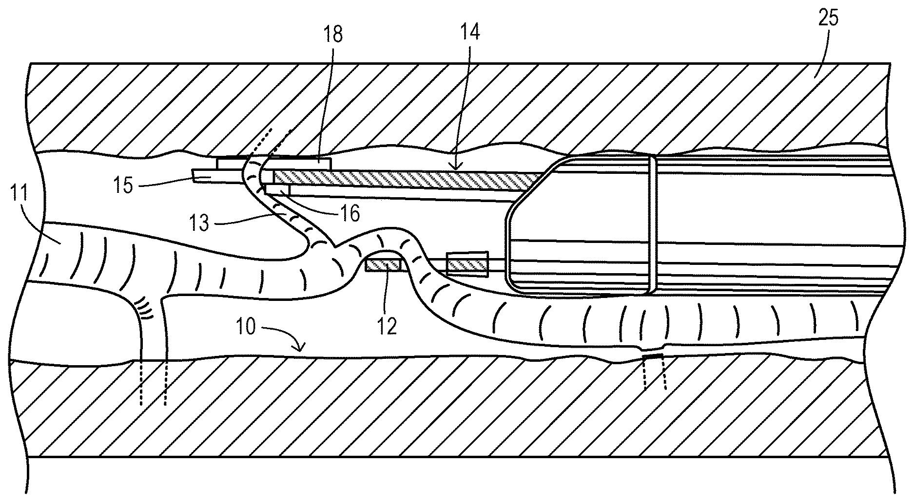
[0031] FIG. 1 shows an endoscopic view from a vessel harvesting system wherein a tunnel 10 has been dissected around a target vessel 11 by blunt dissection as known in the art. A vessel keeper includes a frame 12 having an opening that captures vessel 11. A side branch 13 extends from vessel 11 to a wall of tunnel 10, and branch 13 must be cut and cauterized as part of preparing vessel 11 for removal from the body.
[0032] A vessel cutter member 14 is shown extending toward branch 13 in order to capture it in a slit 15. Cutter 14 has a cutter electrode 16 at a base of slit 15. An outer (tunnel-facing) side of cutter 14 is shown in FIG. 2. Cutter 14 is formed by a plate 17 carrying grounding electrodes 18 and 19. FIGS. 3 and 4 show an alternate design of a vessel cutter tip 20 with a side branch 21 advancing in a slit 22. Side branch 21 may be compressed as it traverses slit 22 until coming into contact with a cutting electrode 23 at the base of slit 22. A grounding electrode 24 is spaced away from slit 22 and is arranged to contact the surface of the tunnel in order to establish electrical continuity so that the vessel to be cut and cauterized forms part of an electrical circuit path between electrodes 23 and 24.
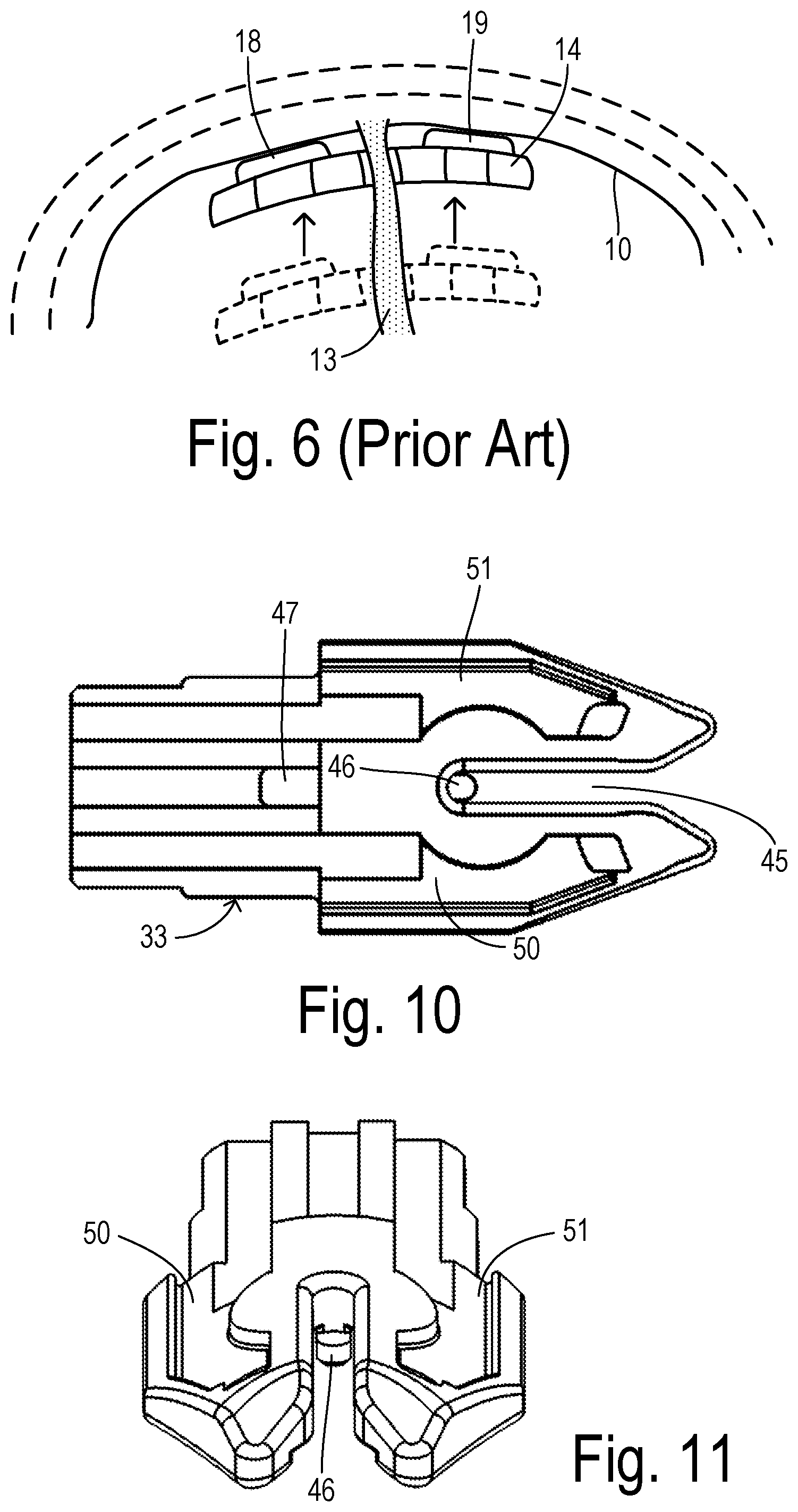
[0033] FIG. 5 shows an insertion member or sleeve 25 of an endoscopic vessel harvester inserted into tunnel 10 and carrying vessel holder 12 and cutter member 14. In order to establish a completed electrical circuit, branch 13 contacts cutting electrode 16 at the same time that grounding electrode 18 contacts a wall of tunnel 10. As shown in FIG. 6, branch 13 is typically initially captured within slit 15 in a region close to vessel 11 and is then moved outwardly in order to obtain contact between the grounding electrodes and tunnel 10 while keeping branch 13 within slit 15. Besides requiring additional time and effort, the need for placement against the tunnel wall increases the region of thermal exposure and thermal spreading to include more than just the branch being cut and cauterized.
[0034] To reduce time and effort and to further limit thermal spreading beyond the branch vessel being cut and cauterized, the present invention provides improved grounding electrodes in a cutter member 30 shown in FIGS. 7-9. Cutter member 30 is extendable from the longitudinal insertion member of an endoscopic vessel harvesting tool, such as the VirtuoSaph Plus.TM. product noted above. Cutter member 30 is constructed of a lower sheath 31, an upper sheath 32, a cutter tip 33, an active cutting electrode 34, grounding electrodes 35 and 36, and ground electrode extensions 37 and 38. Lower sheath 31 includes slots 39 for receiving electrode 34 and extensions 37 and 38. Tabs 40 and 41 of upper sheath 32 fit into corresponding notches 42 and 43 in lower sheath 31. Sheaths 31 and 32 can be fabricated from a molded polycarbonate.
[0035] Tip 33 is shown in greater detail in FIGS. 10 and 11. It is preferably formed of a ceramic material and can be joined to the sheaths using a high temperature RTV silicone adhesive. A distal slot 45 divides a distal end of tip 33 into left and right wing sections having recesses 50 and 51 for receiving the ground electrodes. A tab 46 extends from a main body of tip 33 at the bottom of slit 45 in order to receive an opening 48 in the end of active cutting electrode 34. An opening 47 is disposed in tip 33 to allow a portion of active cutting electrode 34 to pass from the bottom side of tip 33 to the top side between the upper and lower sheaths.
[0036] FIGS. 12 and 13 show tip 33 after assembly of active electrode 34 and grounding electrodes 35 and 36. Grounding electrodes 35 and 36 are symmetrical about slit 34 and may each include a forward nose extension captured in matching features in respective recesses 50 and 51. In addition, grounding electrodes 35 and 36 may be retained within recesses 50 and 51 by welding them to the electrode extensions and/or by use of adhesives. FIG. 13 illustrates a gap G between a forward edge of active electrode 34 and an upright jamb surface 53 which provides a branch grounding surface. When a branch vessel is in contact with electrode 34 and jamb grounding surface 53 and the high-frequency power signal is applied, then the electrocautery heating is applied only to the branch being cauterized so that less heat spreads to the tunnel or surrounding structures.
[0037] FIG. 14 shows a distal end of cutter member 30 with electrode extensions 37 and 38 protruding from lower and upper sheaths 31 and 32 so that they are exposed within recesses 50 and 51. Grounding electrodes 35 and 36 as shown in FIG. 15 are placed into recesses 50 and 51 as shown in FIG. 16. Electrodes 35 and 36 are welded for electrical continuity to extensions 37 and 38 thereby allowing independent switching of ground electrodes 35 and 36 to the bipolar high-frequency power source. For cutting/cauterizing a branch, one side of the power source is applied to cutting electrode 34 and the other side of the power source is applied to grounding electrodes 35 and 36 simultaneously. For spot cautery of surfaces (e.g., the tunnel surface), one side of the power source is applied to grounding electrode 35 and the other side of the power source is applied to grounding electrode 36.
[0038] FIG. 17 shows a front view of tip 33 looking into slot 45 toward 46. Slit 45 defines a width D1 which is adapted to accommodate entry of a range of branch vessel sizes into slit 45. Distance D1 may preferably be about 1.0 mm and a longitudinal depth of slit 45 may be about 10 mm.
[0039] FIG. 18 is a front view of tip 33 with active electrode 34 and grounding electrodes 35 and 36 installed. Ground electrode 35 has a raised longitudinal ridge 55 and a spot cautery wing 56. Ground electrode 36 has a raised longitudinal ridge 57 and a spot cautery wing 58. Ridges 55 and 57 define i) a grounding electrode spacing D2 which is greater than or equal to D1 and ii) a height H1 extending above slit 45. Preferably, distance D2 is slightly greater than or equal to distance D1.
[0040] Ridges 55 and 57 define upright jamb surfaces 53 and 60 configured to contact the side branches where they exit slit 45 (i.e., at a spot remote from cutting electrode 34). Jamb surfaces 53 and 60 are substantially parallel with each other and with the sides of slit 45. Preferably, each upright jamb surface 53 and 60 is located within 0.3 mm of an upright profile of slit 45 (i.e., each is within 0.3 mm of an imaginary parallel plane that extends up from the sides of slit 45 such that distance D2 is no more than 0.6 mm greater than distance D1). Height H1 of upright jamb surfaces 53 and 60 is preferably about 0.5 mm or greater.
[0041] Raised ridges 55 and 57 have upper corners or edges 61 and 62 along the top of jamb surfaces 53 and 60 which are curved to avoid any sharp edges that could damage the side branches or other tissues during manipulation of the harvester tool. Preferably, edges 61 and 62 have a radius of at least 0.1 mm.
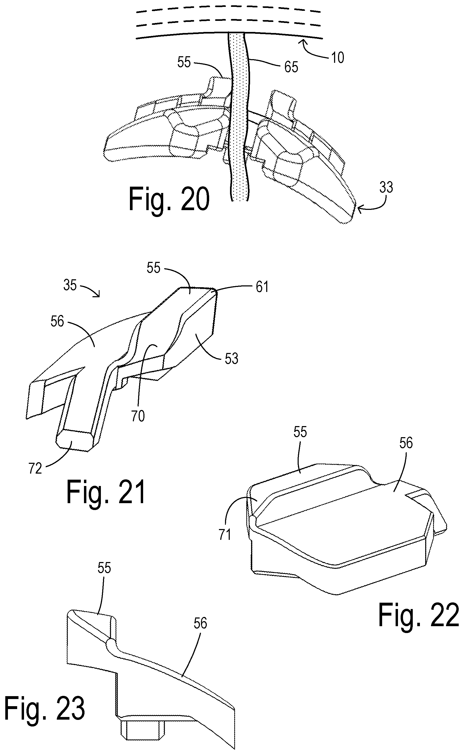
[0042] When a side branch vessel is being cut which has a diameter equal to or greater than separation distance D2 between electrodes 35 and 36, then a sufficient grounding contact will automatically be made with the branch vessel. In the event of a side branch having a diameter less than D2, then a pivoting or rolling motion of the insertion member can ensure sufficient contact as shown in FIGS. 19 and 20. Thus, a branch vessel 65 is shown having a diameter less than the slit width so that it contacts neither one of raised ridges 55 or 57. By pivoting the insertion member as shown in FIG. 20, cutter member 33 and its attached structures rotate until vessel 65 makes good contact with raised ridge 55. The degree of movement is much less than having to relocate to the wall surface of tunnel 10, and the application of cauterizing heat is still restricted to branch vessel 65 rather than being applied directly to tunnel 10.
[0043] FIGS. 21-23 show grounding electrode 35 in greater detail. In order to obtain smooth movement within the tunnel, raised ridge 55 has a ramped leading edge 70 and a ramped trailing edge 71. Forward nose 72 fits into a corresponding portion of the recess within the tip for positively retaining electrode 35. Spot cautery wing 56 extends laterally away from raised ridge 55 (laterally away from the slit) to provide a surface configured to engage the tunnel surface when it is desired to perform spot cautery by energizing a signal between the grounding electrodes. Preferably, spot cautery wing 56 defines a curved planar surface as shown in FIGS. 21-23 to easily conform to the tunnel surface and to optimize the contact interface with the tissues at the tunnel wall so that a desired region can be spot cauterized. A preferred material for the electrodes is stainless steel or other biocompatible materials such as titanium which can be fabricated by metal injection molding.
* * * * *
D00000
D00001
D00002
D00003
D00004
D00005
D00006
D00007
D00008
D00009
D00010
D00011
XML
uspto.report is an independent third-party trademark research tool that is not affiliated, endorsed, or sponsored by the United States Patent and Trademark Office (USPTO) or any other governmental organization. The information provided by uspto.report is based on publicly available data at the time of writing and is intended for informational purposes only.
While we strive to provide accurate and up-to-date information, we do not guarantee the accuracy, completeness, reliability, or suitability of the information displayed on this site. The use of this site is at your own risk. Any reliance you place on such information is therefore strictly at your own risk.
All official trademark data, including owner information, should be verified by visiting the official USPTO website at www.uspto.gov. This site is not intended to replace professional legal advice and should not be used as a substitute for consulting with a legal professional who is knowledgeable about trademark law.