Implant Inserter
HOLLIS; M. Chad
U.S. patent application number 16/483409 was filed with the patent office on 2020-01-09 for implant inserter. The applicant listed for this patent is CROSSROADS EXTREMITY SYSTEMS, LLC. Invention is credited to M. Chad HOLLIS.
| Application Number | 20200008807 16/483409 |
| Document ID | / |
| Family ID | 63041104 |
| Filed Date | 2020-01-09 |


View All Diagrams
| United States Patent Application | 20200008807 |
| Kind Code | A1 |
| HOLLIS; M. Chad | January 9, 2020 |
IMPLANT INSERTER
Abstract
An implant delivery system includes an implant and an inserter releasably connectable to the implant. When the inserter is connected to the implant, actuating the inserter moves the implant between a free state and an elastically deformed state. The implant has a body with a bone facing surface and bilaterally protruding connecting means. The inserter has hooks that engage under the connecting means. The hooks and the rest of the inserter are proximal to the bone facing surface so that the implant may be fully seated against a bone surface while connected to the inserter.
| Inventors: | HOLLIS; M. Chad; (Collierville, TN) | ||||||||||
| Applicant: |
|
||||||||||
|---|---|---|---|---|---|---|---|---|---|---|---|
| Family ID: | 63041104 | ||||||||||
| Appl. No.: | 16/483409 | ||||||||||
| Filed: | February 2, 2018 | ||||||||||
| PCT Filed: | February 2, 2018 | ||||||||||
| PCT NO: | PCT/US2018/016994 | ||||||||||
| 371 Date: | August 2, 2019 |
Related U.S. Patent Documents
| Application Number | Filing Date | Patent Number | ||
|---|---|---|---|---|
| 62455361 | Feb 6, 2017 | |||
| Current U.S. Class: | 1/1 |
| Current CPC Class: | A61B 17/0644 20130101; A61B 17/068 20130101; A61B 2017/0645 20130101; A61B 17/0642 20130101; A61B 2017/0648 20130101; A61F 2220/0025 20130101; A61B 17/0682 20130101; A61B 17/10 20130101; A61F 2/4603 20130101 |
| International Class: | A61B 17/10 20060101 A61B017/10; A61B 17/064 20060101 A61B017/064 |
Claims
1. An implant delivery system comprising: an implant comprising a body, a first bone engagement member, a second bone engagement member, a first connecting means, and a second connecting means, wherein the body extends between a first end and an opposite second end to establish a longitudinal direction of the body, wherein the first bone engagement member extends from the first end transverse to the body, wherein the second bone engagement member extends from the second end transverse to the body beside the first bone engagement member, wherein the first connecting means extends outwardly from the first end along the longitudinal direction, wherein the second connecting means extends outwardly from the second end along the longitudinal direction, wherein the implant comprises an implant free state in which the first and second bone engagement members converge as they extend from the body, and an elastically deformed state in which the first and second bone engagement members are spread apart relative to the implant free state; and an inserter removably connectable to the implant, the inserter comprising a first hook, a second hook, and a ram pin, wherein the first and second hooks face each other and are movable proximally and distally relative to the ram pin; wherein when the inserter is connected to the implant, the first hook receives the first connecting means and the second hook receives the second connecting means, wherein moving the first and second hooks proximally relative to the ram pin causes the body to elastically deform against the resistance of the ram pin to move the implant into the elastically deformed state.
2. An implant delivery system comprising: an implant comprising a body, a first connection feature, and a second connection feature, wherein the implant body comprises a proximal surface and an opposite distal surface, wherein the implant body extends between a first end and an opposite second end to establish a longitudinal direction of the implant body, wherein the first connection feature comprises a distal surface that is offset from the implant body distal surface toward the implant body proximal surface, wherein the first connection feature is at the first end, wherein the second connection feature comprises a distal surface that is offset from the implant body distal surface toward the implant body proximal surface, wherein the second connection feature is at the second end, wherein the implant is movable between a free state and an elastically deformed state; and an inserter that is removably connectable to the implant, wherein the inserter comprises a third connection feature, a fourth connection feature, and a static support, wherein the third and fourth connection features are movable proximally and distally relative to the static support; wherein when the inserter is connected to the implant, the first connection feature engages the third connection feature, the second connection feature engages the fourth connection feature, the implant body proximal surface faces the static support, and the entire inserter is proximal to the implant body distal surface; wherein moving the third and fourth connection features proximally and distally relative to the static support moves the implant between the free state and the elastically deformed state.
3. The implant delivery system of claim 2, wherein the first connection feature extends outwardly from the first end along the longitudinal direction, wherein the second connection feature extends outwardly from the second end along the longitudinal direction.
4. The implant delivery system of claim 2, wherein the implant comprises a first fixation member and a second fixation member, wherein the first fixation member is at the first end, wherein the second fixation member is at the second end.
5. The implant delivery system of claim 4, wherein the first and second fixation members extend from the implant body distal surface.
6. The implant delivery system of claim 4, wherein the first and second connection features are lateral to the first and second fixation members.
7. The implant delivery system of claim 4, wherein in the free state, the first and second fixation members converge as they extend from the implant body, wherein in the elastically deformed state, the first and second fixation members are spread apart relative to the free state.
8. The implant delivery system of claim 2, wherein when the inserter is connected to the implant, the first connection feature distal surface engages a proximal surface of the third connection feature and the second connection feature distal surface engages a proximal surface of the fourth connection feature.
9. The implant delivery system of claim 2, wherein moving the third and fourth connection features proximally relative to the static support causes the implant body to elastically deform against the static support to move the implant into the elastically deformed state.
10. The implant delivery system of claim 2, wherein the inserter comprises a distal groove, wherein when the inserter is connected to the implant, a proximal portion of the implant body is received in the distal groove.
11. The implant delivery system of claim 10, wherein the static support is located within the distal groove.
12. The implant delivery system of claim 2, wherein the static support remains in contact with the implant body proximal surface at all times while the inserter is connected to the implant.
Description
TECHNICAL FIELD
[0001] The present disclosure relates to an implant and a corresponding inserter. More specifically, the present disclosure is made in the context of a bone staple and a corresponding inserter. However, the disclosed technology is broadly applicable outside this context, as will be apparent to one of skill in the art.
[0002] The staple has a free state, or relaxed state, which is its shape when no external forces are acting upon the staple, other than gravity perhaps. In the free state, the staple is not elastically or plastically deflected or deformed. The staple may experience loads that are below a threshold for elastic or plastic deflection or deformation. In the free state, the staple legs converge at their distal tips. The staple may be made from high elasticity materials such as nitinol and/or polyetheretherketone (PEEK) so that the staple may be elastically deformed by an external force, and then resume the free state when the external force is removed.
[0003] The inserter securely and releasably couples to the staple. When actuated, the inserter urges the staple out of the free state into a continuum of elastically deformed states in which the staple legs a) progressively approach a parallel condition, b) achieve a parallel condition, or c) progressively diverge at their distal tips. When the inserter is uncoupled from the bone staple, the bone staple resumes the free state, or attempts to do so. When the bone staple is implanted in bone, then the staple may only be able to partially relax toward the free state due to the resistance of the bone.
SUMMARY
[0004] In an aspect of the technology, an implant delivery system includes: an implant including a body, a first bone engagement member, a second bone engagement member, a first connecting means, and a second connecting means, wherein the body extends between a first end and an opposite second end to establish a longitudinal direction of the body, wherein the first bone engagement member extends from the first end transverse to the body, wherein the second bone engagement member extends from the second end transverse to the body beside the first bone engagement member, wherein the first connecting means extends outwardly from the first end along the longitudinal direction, wherein the second connecting means extends outwardly from the second end along the longitudinal direction, wherein the implant includes an implant free state in which the first and second bone engagement members converge as they extend from the body, and an elastically deformed state in which the first and second bone engagement members are spread apart relative to the implant free state; and an inserter removably connectable to the implant, the inserter including a first hook, a second hook, and a ram pin, wherein the first and second hooks face each other and are movable proximally and distally relative to the ram pin; wherein when the inserter is connected to the implant, the first hook receives the first connecting means and the second hook receives the second connecting means, wherein moving the first and second hooks proximally relative to the ram pin causes the body to elastically deform against the resistance of the ram pin to move the implant into the elastically deformed state.
[0005] In another aspect of the technology, an implant delivery system includes: an implant including a body, a first connection feature, and a second connection feature, wherein the implant body includes a proximal surface and an opposite distal surface, wherein the implant body extends between a first end and an opposite second end to establish a longitudinal direction of the implant body, wherein the first connection feature includes a distal surface that is offset from the implant body distal surface toward the implant body proximal surface, wherein the first connection feature is at the first end, wherein the second connection feature includes a distal surface that is offset from the implant body distal surface toward the implant body proximal surface, wherein the second connection feature is at the second end, wherein the implant is movable between a free state and an elastically deformed state; and an inserter that is removably connectable to the implant, wherein the inserter includes a third connection feature, a fourth connection feature, and a static support, wherein the third and fourth connection features are movable proximally and distally relative to the static support; wherein when the inserter is connected to the implant, the first connection feature engages the third connection feature, the second connection feature engages the fourth connection feature, the implant body proximal surface faces the static support, and the entire inserter is proximal to the implant body distal surface; wherein moving the third and fourth connection features proximally and distally relative to the static support moves the implant between the free state and the elastically deformed state.
[0006] Embodiments of this aspect may include one or more of the following attributes. The first connection feature extends outwardly from the first end along the longitudinal direction, wherein the second connection feature extends outwardly from the second end along the longitudinal direction. The implant includes a first fixation member and a second fixation member, wherein the first fixation member is at the first end, wherein the second fixation member is at the second end. The first and second fixation members extend from the implant body distal surface. The first and second connection features are lateral to the first and second fixation members. In the free state, the first and second fixation members converge as they extend from the implant body, wherein in the elastically deformed state, the first and second fixation members are spread apart relative to the free state. When the inserter is connected to the implant, the first connection feature distal surface engages a proximal surface of the third connection feature and the second connection feature distal surface engages a proximal surface of the fourth connection feature. Moving the third and fourth connection features proximally relative to the static support causes the implant body to elastically deform against the static support to move the implant into the elastically deformed state. The inserter includes a distal groove, wherein when the inserter is connected to the implant, a proximal portion of the implant body is received in the distal groove. The static support is located within the distal groove. The static support remains in contact with the implant body proximal surface at all times while the inserter is connected to the implant.
BRIEF DESCRIPTION OF THE DRAWINGS
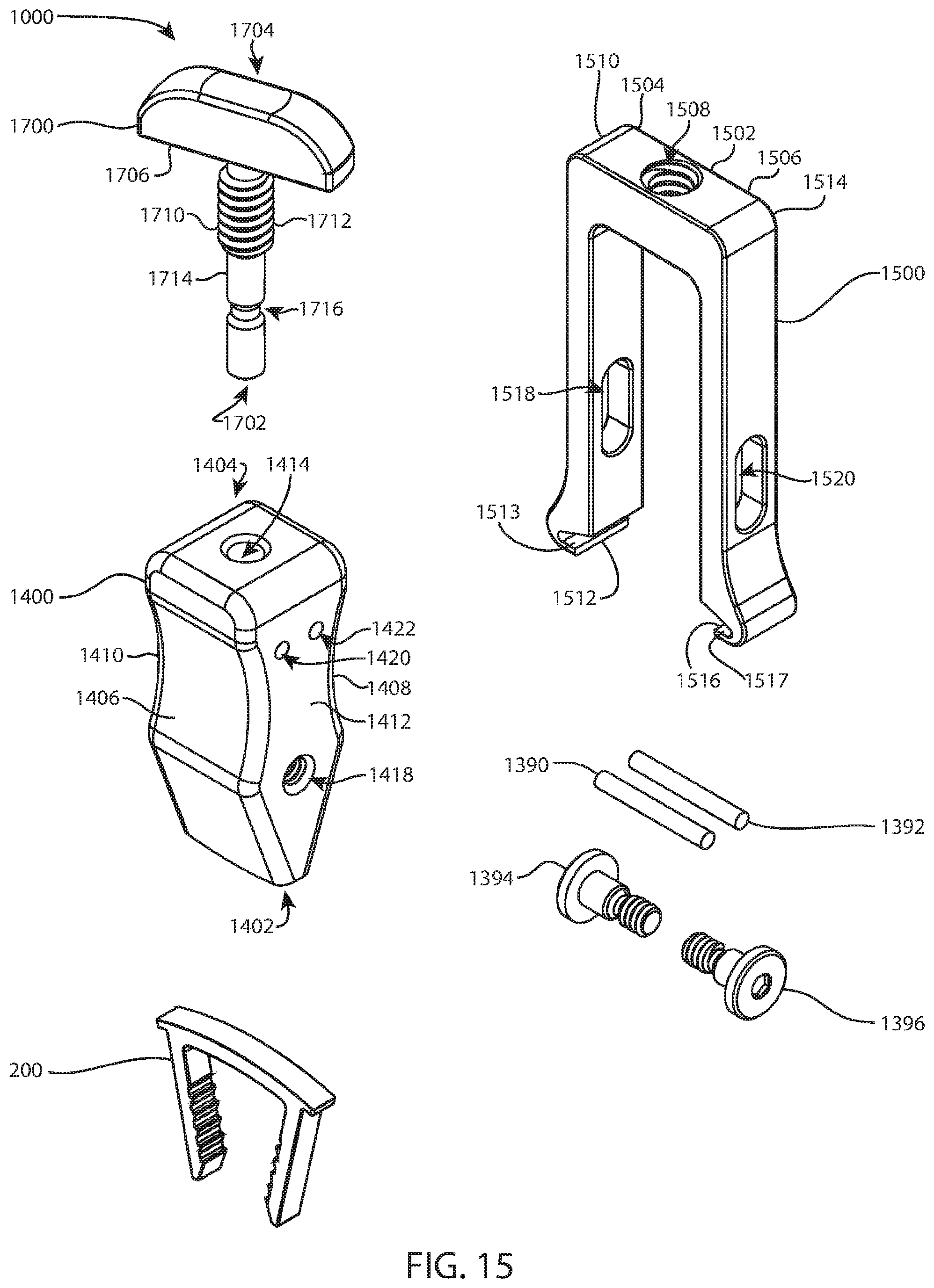
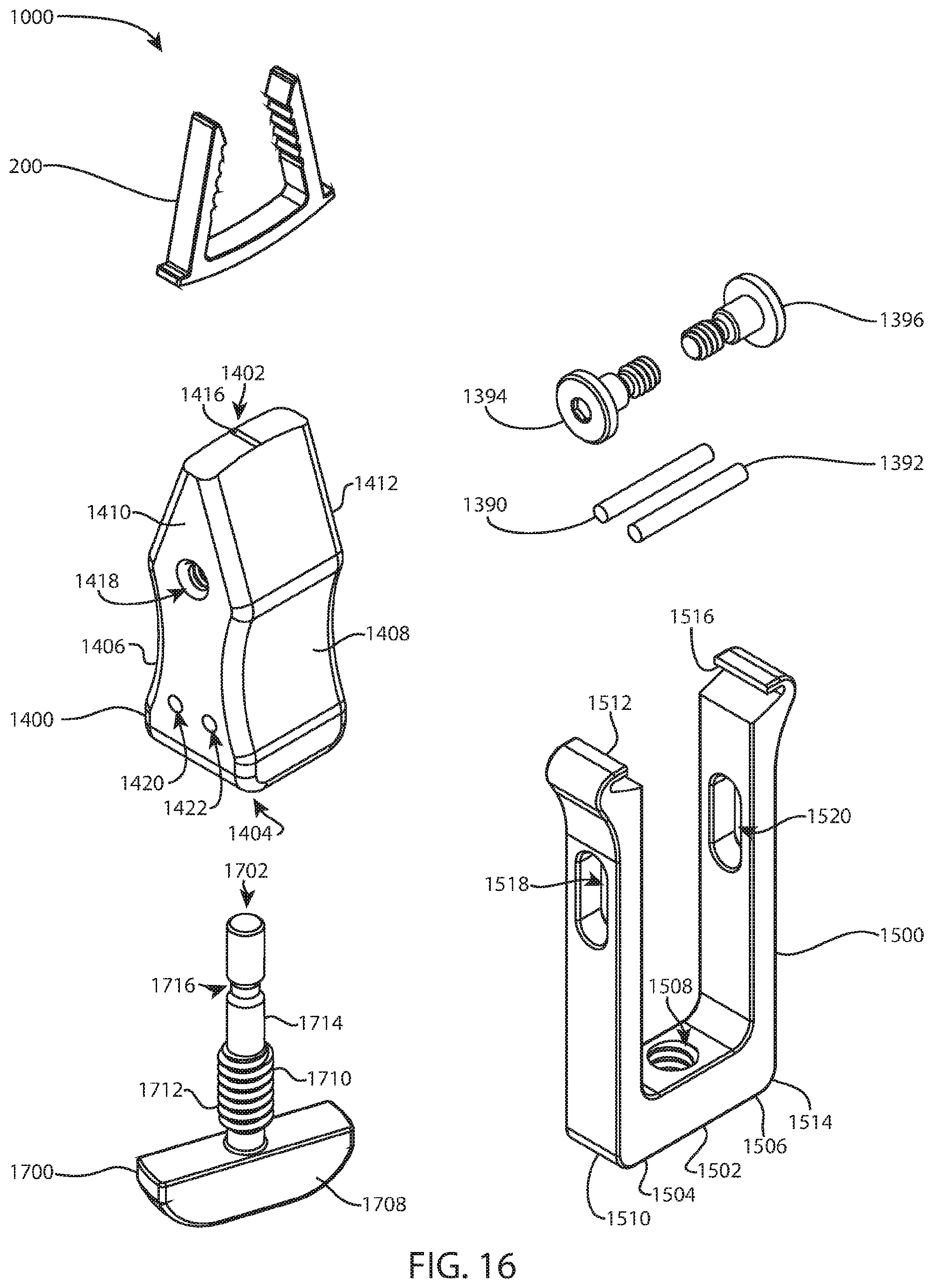
[0007] Exemplary embodiments of the technology will become more fully apparent from the following description and appended claims, taken in conjunction with the accompanying drawings. Understanding that these drawings depict only exemplary embodiments and are, therefore, not to be considered limiting of the scope of the technology, the exemplary embodiments will be described with additional specificity and detail through use of the accompanying drawings in which:
[0008] FIG. 1 is a perspective view of a system with an implant coupled to an inserter;
[0009] FIG. 2 is another perspective view of the system of FIG. 1 from a different direction;
[0010] FIG. 3 is a side view of the system of FIG. 1;
[0011] FIG. 4 is a cross sectional view of the system of FIG. 1, taken along section line 4-4 of FIG. 3;
[0012] FIG. 5 is an exploded perspective view of the system of FIG. 1;
[0013] FIG. 6 is another exploded perspective view of the system of FIG. 1 from a different direction;
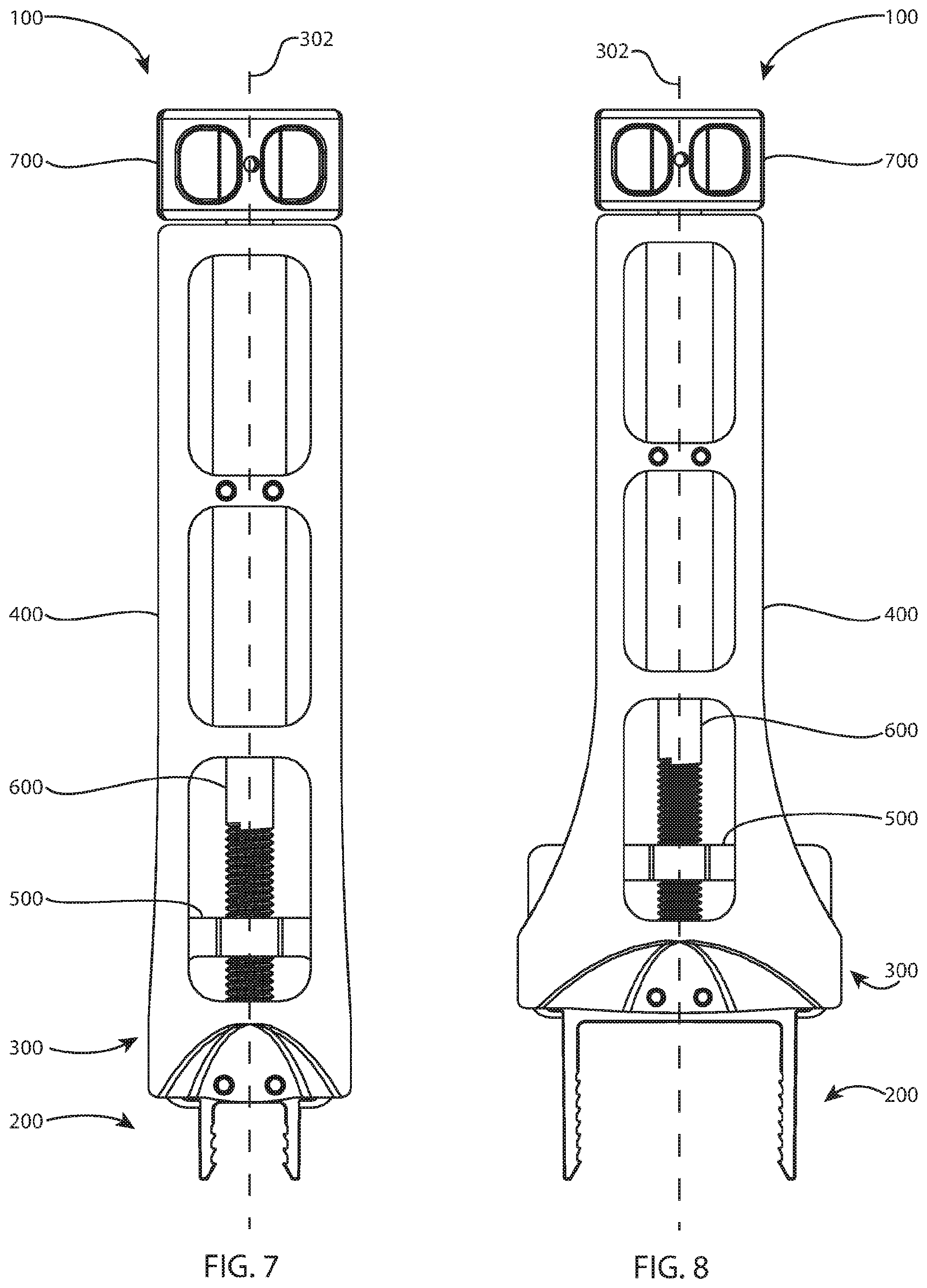
[0014] FIG. 7 is a front view of the system of FIG. 1 designed for a small size implant;
[0015] FIG. 8 is a front view of the system of FIG. 1 designed for a large size implant;
[0016] FIG. 9 is a front view of the implant of FIG. 1;
[0017] FIG. 10 is a perspective view of a body of the inserter of FIG. 1;
[0018] FIG. 11 is a perspective view of another system with the implant of FIG. 1 coupled to another inserter;
[0019] FIG. 12 is another perspective view of the system of FIG. 11 from a different direction;
[0020] FIG. 13 is a side view of the system of FIG. 11;
[0021] FIG. 14 is a cross sectional view of the system of FIG. 11, taken along section line 14-14 of FIG. 13;
[0022] FIG. 15 is an exploded perspective view of the system of FIG. 11;
[0023] FIG. 16 is another exploded perspective view of the system of FIG. 11 from a different direction;
[0024] FIG. 17 is a front view of the system of FIG. 11 with the implant in a free state and a jaw member of the inserter in a distal position; and
[0025] FIG. 18 is a front view of the system of FIG. 11 with the implant in an elastically deformed state and the jaw member of the inserter in a proximal position.
DETAILED DESCRIPTION
[0026] Exemplary embodiments of the technology will be best understood by reference to the drawings, wherein like parts are designated by like numerals throughout. It will be readily understood that the components of the technology, as generally described and illustrated in the figures herein, could be arranged and designed in a wide variety of different configurations. Thus, the following more detailed description of the embodiments of the apparatus, system, and method is not intended to limit the scope of the invention, as claimed, but is merely representative of exemplary embodiments of the technology.
[0027] The phrases "connected to," "coupled to" and "in communication with" refer to any form of interaction between two or more entities, including mechanical, electrical, magnetic, electromagnetic, fluid, and thermal interaction. Two components may be functionally coupled to each other even though they are not in direct contact with each other. The term "abutting" refers to items that are in direct physical contact with each other, although the items may not necessarily be attached together. The phrase "fluid communication" refers to two features that are connected such that a fluid within one feature is able to pass into the other feature.
[0028] The word "exemplary" is used herein to mean "serving as an example, instance, or illustration." Any embodiment described herein as "exemplary" is not necessarily to be construed as preferred or advantageous over other embodiments. While the various aspects of the embodiments are presented in drawings, the drawings are not necessarily drawn to scale unless specifically indicated.
[0029] Standard medical planes of reference and descriptive terminology are employed in this specification. While these terms are commonly used to refer to the human body, certain terms are applicable to physical objects in general.
[0030] A standard system of three mutually perpendicular reference planes is employed. A sagittal plane divides a body into right and left portions. A coronal plane divides a body into anterior and posterior portions. A transverse plane divides a body into superior and inferior portions. A mid-sagittal, mid-coronal, or mid-transverse plane divides a body into equal portions, which may be bilaterally symmetric. The intersection of the sagittal and coronal planes defines a superior-inferior or cephalad-caudal axis. The intersection of the sagittal and transverse planes defines an anterior-posterior axis. The intersection of the coronal and transverse planes defines a medial-lateral axis. The superior-inferior or cephalad-caudal axis, the anterior-posterior axis, and the medial-lateral axis are mutually perpendicular.
[0031] Anterior means toward the front of a body. Posterior means toward the back of a body. Superior or cephalad means toward the head. Inferior or caudal means toward the feet or tail. Medial means toward the midline of a body, particularly toward a plane of bilateral symmetry of the body. Lateral means away from the midline of a body or away from a plane of bilateral symmetry of the body. Axial means toward a central axis of a body. Abaxial means away from a central axis of a body. Ipsilateral means on the same side of the body. Contralateral means on the opposite side of the body. Proximal means toward the trunk of the body. Proximal may also mean toward a user or operator. Distal means away from the trunk. Distal may also mean away from a user or operator. Dorsal means toward the top of the foot. Plantar means toward the sole of the foot. Varus means deviation of the distal part of the leg below the knee inward, resulting in a bowlegged appearance. Valgus means deviation of the distal part of the leg below the knee outward, resulting in a knock-kneed appearance.
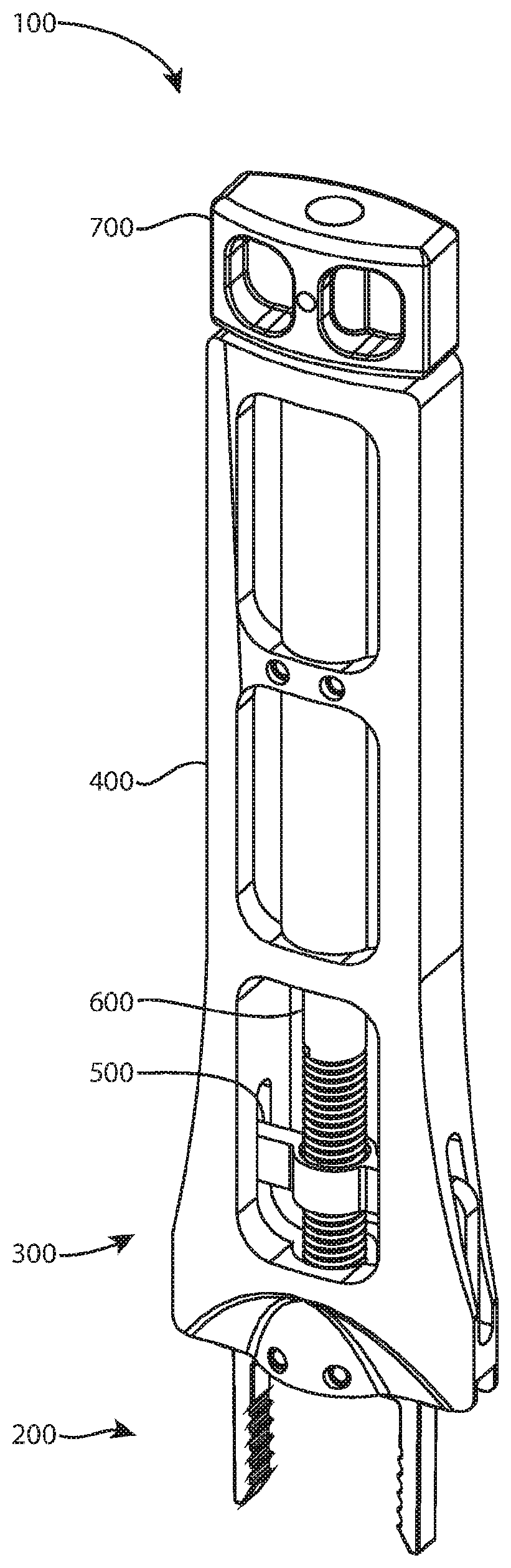
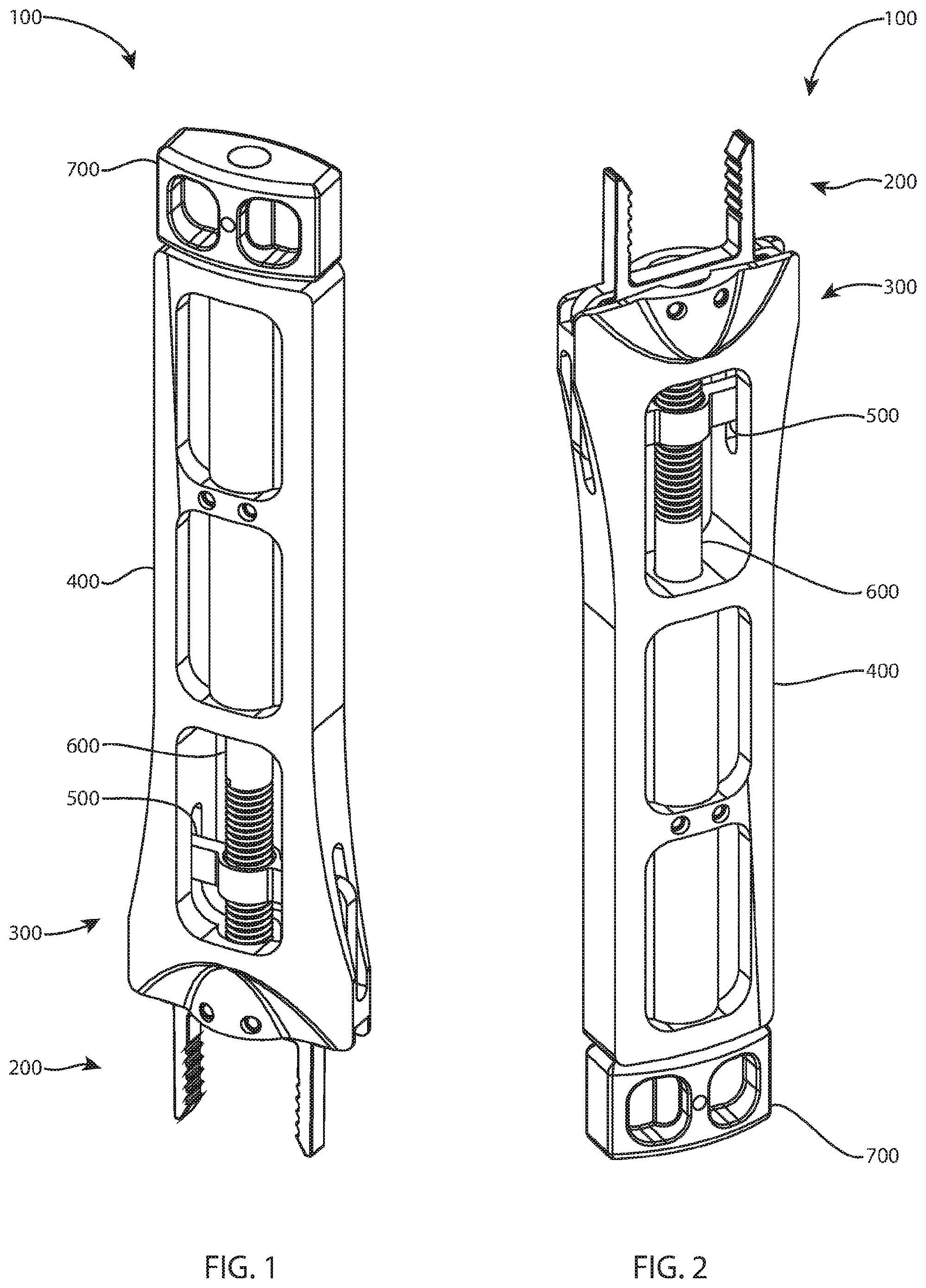
[0032] Referring to FIGS. 1 and 2, an implant delivery system 100 includes an implant 200 and an inserter 300. The implant 200 is shown coupled to the inserter 300, the implant in an elastically deformed state. The illustrated implant 200 is a compression bone staple.
[0033] The implant 200 may be identical to the implant embodiment 2200 described in International Patent Application Serial No. PCT/US2015/039551.
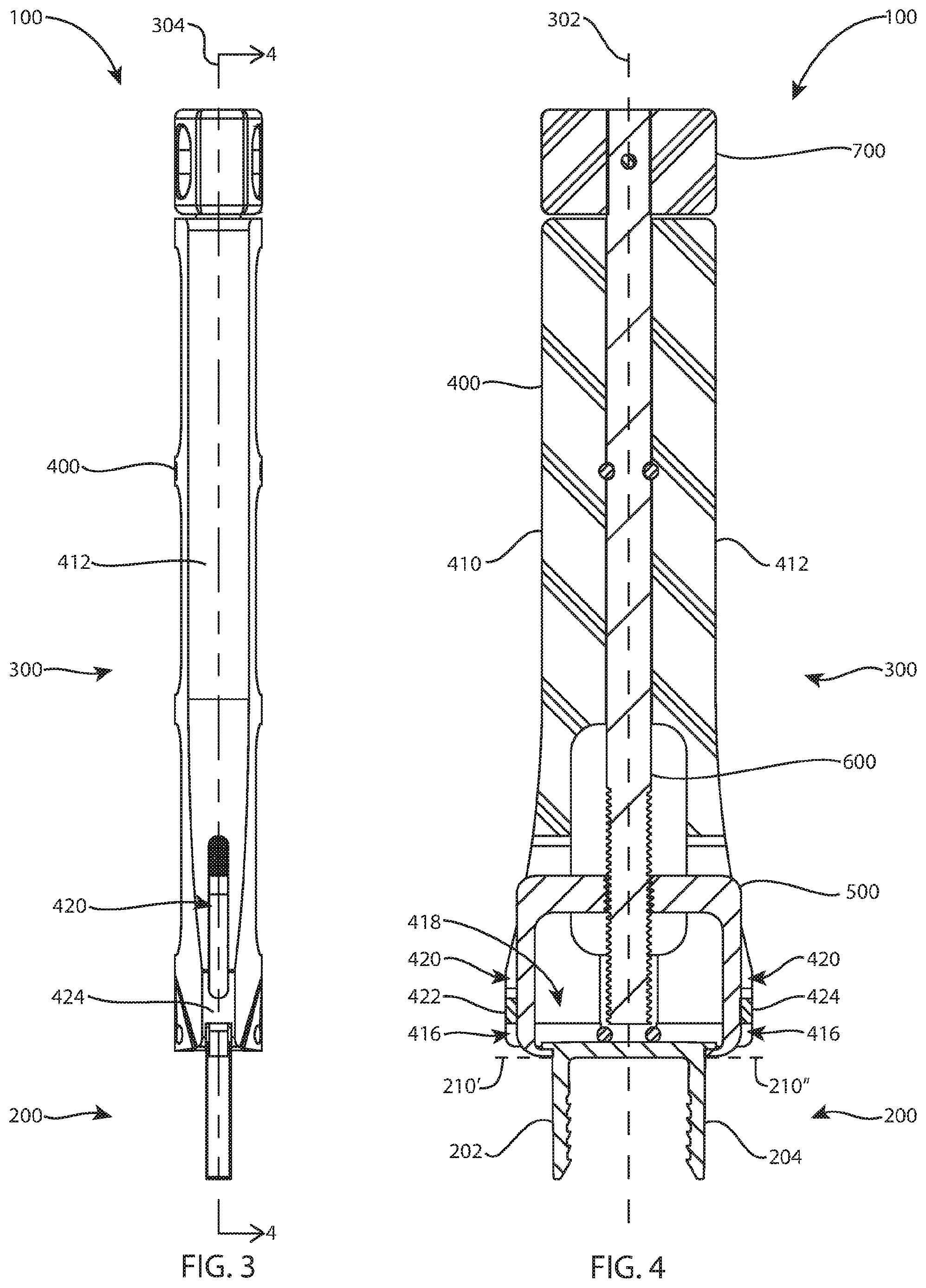
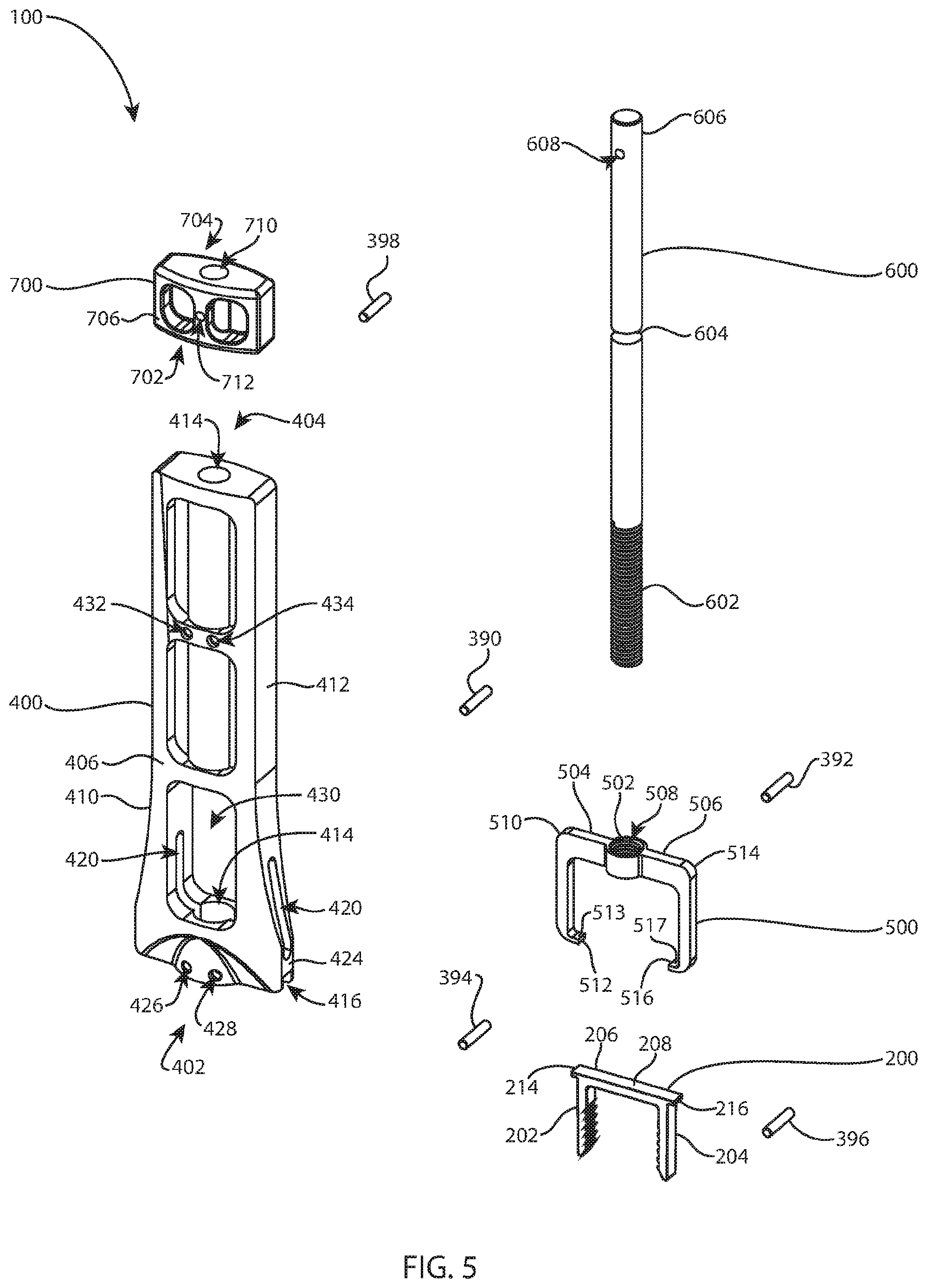
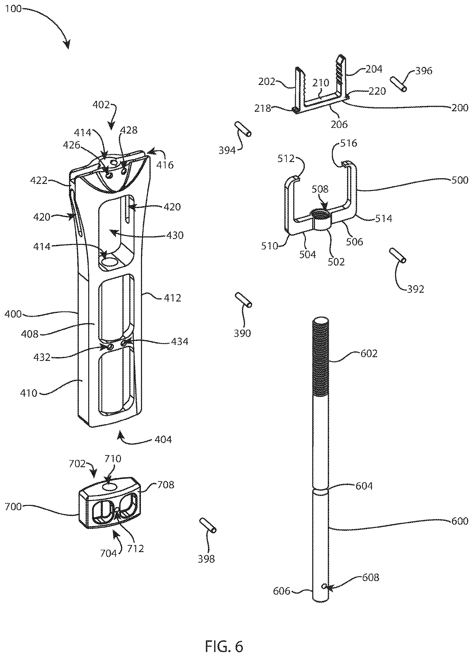
[0034] Referring to FIGS. 1-6 and 9, the implant 200 may include bone engaging members 202 and 204 which may be integral to an implant bridge 206, also referred to as an implant body. Alternatively, the bone engaging members 202, 204 may be separate parts that are connected to the implant body. The bone engaging members 202 and 204 may be referred to as legs or fixation members. The bone engaging member 202 extends from a left end 230 of the implant bridge 206 and the bone engaging member 204 extends from an opposite right end 232 of the implant bridge 206. Bone engaging member 202 has a proximal end 234 attached to the left end 230 of the implant bridge 206 and an opposite distal end 236 which is a free end. Bone engaging member 204 has a proximal end 238 attached to the right end 232 of the implant bridge 206 and an opposite distal end 240 which is a free end. Implant bridge 206 has an upper surface 208 and a lower surface 210. The upper surface 208 may be referred to as a proximal surface. The lower surface 210 may be referred to as a bone facing surface or a distal surface. Bone engaging member 202 extends from the lower surface 210 beside bone engaging member 204. The bone engaging members 202 and 204 may have features 212 that may improve bone purchase or improve pull out strength of the implant 200 from bone or soft tissue. The features 212 may be referred to as teeth or serrations. The features 212 are shown on facing sides of the bone engaging members 202, 204 but may be on any or all sides of the bone engaging members. The implant 200 may have projections or other connecting means 214 and 216 for connection with a means of insertion, such as inserter 300. The connecting means 214, 216 may be referred to as tabs, ears, protrusions, retainers, wings, retaining members, or connection features. The connecting means 214 and 216 are shown extending sideways outwardly from the ends 230, 232 of the bridge 206, respectively, along a longitudinal direction established between the left and right ends 230, 232 of the bridge. The connecting means 214 and 216 are shown lateral to the bone engaging members 202 and 204. However, in other examples, the connecting means may extend outwardly from the ends of the bridge along a front to back direction. These examples may include four connecting means: left front, left back, right front, and right back. The connecting means 214 and 216 may have lower surfaces 218 and 220 respectively that may releasably engage with a means of insertion that may allow the inserter 300 or other means of insertion to be side loading, top loading or pivotably loaded. For example, the inserter 300 may be described as side loading or pivotably loading. The lower surfaces 218, 220 may be referred to as bone facing surfaces or distal surfaces. Referring to FIGS. 4 and 9, the lower surfaces 218, 220 are proximally spaced apart, or proximally offset, from the lower surface 210 toward the upper surface 208. The dashed extension lines 210' and 210'' in FIGS. 4 and 9 show the level of the lower surface 210 versus the lower surfaces 218, 220.
[0035] The means of insertion may maintain an implant in a first configuration thereby allowing a second implant configuration once the implant is disassembled from the implant. The first configuration may be an elastically deformed state, for example an insertion state. The second configuration may be a free state or an implanted state. The means of insertion may utilize features similar to connecting means 214 and 216 in combination with other surfaces such as top surface 208. This combination of means of insertion may be used to maintain one or more features or arms or projections in a particular configuration. This combination of means of insertion may create a bending modality, such as a three point or four point bend, to maintain a specific implant configuration or combination of configurations. A combination of surfaces and means of insertion, such as connecting means 214, may be used on the entire implant or portions of an implant to create or maintain a particular configuration of an implant. For example, a tab such as 214 and top surface, such as 208 may be used to maintain one side of an implant or one arm of an implant in a particular configuration. When disassembled, that arm may have a configuration that is different from or the same as the configuration of the rest of the implant.
[0036] Referring to FIG. 9, the implant 200 is shown uncoupled from the inserter 300. The implant 200 is in a free state, or relaxed state, which is the shape of the implant 200 when no external forces are acting upon the implant 200, other than gravity perhaps; the implant 200 experiences no elastic or plastic deflection or deformation. However, in the free state, the implant 200 may experience loads that are below a threshold for elastic or plastic deflection or deformation. In the free state, the bone engaging members 202 and 204 converge as they extend away from the bridge 206 so that the distal ends 236, 240 are closer together than the proximal ends 234, 238. An angle 222 is formed between the converging bone engaging members 202 and 204 in the free state. The angle 222 opens toward the bridge 206. The angle 222 may be referred to as a free state angle.
[0037] The implant 200 may be moved between the free state and an elastically deformed state by elastically deforming some or all of the implant 200. For example, elastically deforming or pressing on the bridge 206 so that it bows down between the bone engaging members 202, 204 causes the distal ends 236, 240 to spread apart. Alternatively, the bone engaging members 202, 204 may be elastically deformed so that the distal ends 236, 240 spread apart or come closer together. The bone engaging members 202, 204 may spread apart in the elastically deformed state so as to become parallel as seen best in FIG. 4. The elastically deformed state may be suitable for implantation of the implant 200, and may thus be referred to as an insertion state or an implantation state.
[0038] Referring to FIGS. 1-6, the inserter 300 may include a body 400, a jaw member 500, a drive shaft 600, a knob 700, a left ram pin 394, a right ram pin 396, a left drive shaft pin 390, a right drive shaft pin 392, and a knob pin 398.
[0039] The illustrated inserter 300 may have a first plane of symmetry along plane 302 of FIG. 4, which is shown edge on and is thus represented by a line 302, and may have a second plane of symmetry along plane 304 of FIG. 3, which is shown edge on and is thus represented by section line 4-4. The first plane of symmetry divides the inserter 300 into identical left and right halves. The first plane of symmetry is also shown in FIGS. 7 and 8. The second plane of symmetry divides the inserter 300 into identical front and back halves. The first and second planes of symmetry are perpendicular to each other. The first and second planes of symmetry may also apply to the implant 200, the body 400, the jaw member 500, the drive shaft 600, and the knob 700. However, in other examples, the inserter 300 and/or implant 200 may have only one plane of symmetry, or no plane of symmetry so that they are asymmetric.
[0040] The body 400 is an elongated part that extends between a distal end 402 and an opposite proximal end 404. The distal end 402 may be referred to as a working portion and the proximal end 404 may be referred to as a handle. The body 400 has a front surface 406, an opposite back surface 408, a left side 410, and an opposite right side 412. A central longitudinal passageway 414 extends through the body 400 between the distal and proximal ends 402, 404. A groove 416 extends across a distal aspect of the distal end 402 from left to right and extends proximally into the body 400 to a first depth measured from the distal aspect. A pocket 418 extends from the groove 416 proximally into the body 400 to intersect a slot 420 that extends through the body 400 between the sides 410, 412 proximal to the groove 416. The slot 420 communicates with the groove 416 via the pocket 418 and is separated from the groove 416 by left and right columns 422, 424 which extend from front to back on either side of the pocket 418. The pocket 418 may be narrower, front to back, than the groove 416 so that the bottom of the groove 416 extends across the front and back sides of the pocket 418 as seen best in FIGS. 4 and 10. Left and right holes 426, 428 extend through the distal end 402 from front to back across the central longitudinal passageway 414. The slot 420 may intersect a window 430 that extends through the body 400 between the front and back surfaces 406, 408. The window 430 may extend proximally past the proximal end of the slot 420. Left and right holes 432, 434 extend through the body 400 proximal to the window 430 (if present) from front to back across the central longitudinal passageway 414.
[0041] The jaw member 500 includes a central body 502 with left and right arms 504, 506. The body 502 may be cylindrical and may include internal threads 508. Other examples may lack internal threads. The left arm 504 extends laterally from the body 502, bends distally at a left elbow 510, extends distally, and terminates in a left hook 512 that cups toward the right arm 506. The right arm 506 extends laterally from the body 502, bends distally at a right elbow 514, extends distally, and terminates in a right hook 516 that cups toward the left arm 504. The right arm 506 may optionally be a mirror image of the left arm 504, as shown in this example. The hooks 512, 516 may be replaced with other connection features that correspond to the particular connecting means of the implant 200, for example the hooks may be replaced with couplings that engage the front-to-back connecting means mentioned above.
[0042] The drive shaft 600 is an elongated cylindrical part with an externally threaded distal portion 602, a circumferential groove 604, and a proximal portion 606 with a transverse hole 608. The groove 604 is between the externally threaded distal portion 602 and the hole 608, in a middle portion of the drive shaft 600.
[0043] The knob 700 has a generally rectangular solid shape. However, the long sides of the rectangle may bow outwards to mimic the shape of the proximal end 404 of the body 400, as best seen in FIG. 5. The knob 700 extends between a distal end 702 and an opposite proximal end 704. The knob 700 has a front surface 706 and an opposite back surface 708. The front and back surfaces 706, 708 may bow outwardly to mimic the shape of the proximal end 404 of the body 400. A central longitudinal passageway 710 extends through the knob 700 between the distal and proximal ends 702, 704. An optional transverse hole 712 extends through the knob 700 between the front and back surfaces 706, 708.
[0044] When the inserter 300 is fully assembled (operatively assembled), the pocket 418 and slot 420 of the body 400 receive the jaw member 500. The jaw member 500 is oriented so that the body 502 is toward the proximal end 404, the arms 504, 506 are between the columns 422, 424, and the hooks 512, 516 are toward the distal end 402. The holes 426, 428 receive ram pins 394, 396. While two holes 426, 428 and two ram pins 394, 396 are shown, a single hole and ram pin may be used instead, preferably centrally located distal to the drive shaft 600. The ram pin(s) may be referred to as static support(s) against whose resistance the implant elastically deforms. In other examples, the ram pin(s) may be replaced by one or more static supports or ram features that are integrally formed with the body 400 or another component part of the inserter 300. The central longitudinal passageway of the body 400 receives the drive shaft 600. The drive shaft 600 is oriented so that the proximal portion 606 is toward the proximal end 404, the groove 604 is between the holes 432, 434, and the distal portion 602 is toward the distal end 402. The holes 432, 434 and the groove 604 receive drive shaft pins 390, 392. The internal threads 508 of the jaw member 500 thread onto the externally threaded distal portion 602. The central longitudinal passageway 710 of the knob 700 receives the proximal portion 606 of the drive shaft 600 with the holes 712, 608 aligned. The holes 712, 608 receive a knob pin 398. Alternatively, the knob 700 may be connected to the drive shaft 600 by overmolding instead of a cross pin.
[0045] A method of assembling the inserter 300 may include any or all of the following steps in any order: threading the jaw member 500 onto the drive shaft 600; inserting the drive shaft 600 in the central longitudinal passageway 414 of the body 400; inserting the jaw member 500 in the slot 420 of the body 400; coupling the knob 700 to the drive shaft 600; inserting the ram pins 394, 396 in the holes 426, 428; inserting the drive shaft pins 390, 392 in the holes 432, 434 and the groove 604; and inserting the knob pin 398 in the holes 712, 608.
[0046] When the inserter 300 is fully assembled, the drive shaft 600 and knob 700 are fixed together. The drive shaft 600 and knob 700 are free to rotate together relative to the body 400 and the jaw member 500. The drive shaft 600 and knob 700 are unable to translate proximal-distal relative to the body 400 due to the pins 390, 392 in the holes 432, 434 and the groove 604. Clockwise rotation of the drive shaft 600 causes the jaw member 500 to move proximally relative to the body 400; counterclockwise rotation of the drive shaft 600 causes the jaw member 500 to move distally relative to the body 400. The upper surface 208 of the bridge 206 of the implant 200 and the ram pins 394, 396 may remain in contact when the jaw member 500 moves proximally.
[0047] In the example shown, the arms 504, 506 of the jaw member 500 are static, meaning that the arms do not move relative to each other as the drive shaft 600 is rotated clockwise or counterclockwise. The static arms may be supported by the columns 422, 424 to prevent the arms from spreading apart laterally, for example when subjected to service loads during use.
[0048] In another example, the arms 504, 506 may be dynamic, meaning that the arms move relative to each other as the drive shaft 600 is rotated clockwise or counterclockwise. The dynamic arms 504, 506 may spread apart as the drive shaft 600 is rotated counterclockwise and the jaw member 500 moves distally relative to the body 400, and may close together as the drive shaft 600 is rotated clockwise and the jaw member 500 moves proximally. The dynamic arms 504, 506 may be squeezed together by the columns 422, 424 as the jaw member moves proximally. The dynamic arms 504, 506 in this example may be designed with geometry that enhances their elastic deflection, and the jaw member 500 may be made from a suitably elastic material.
[0049] When the implant 200 and the inserter 300 are fully assembled (operatively assembled), the groove 416 receives a proximal portion of the bridge 206, the ram pins 394, 396 may be adjacent to or may contact the upper surface 208, the hooks 512, 516 engage under the connecting means 214, 216, and the bone engaging members 202, 204 extend distally from the inserter 300. Proximal surfaces 513, 517 of the hooks 512, 516 may engage the lower surfaces 218, 220 of the connecting means 214, 216. The implant 200 and the inserter 300 may be fully assembled with the implant 200 in the free state; the four points of contact (ram pins 394, 396 and hooks 512, 516) acting on the bridge 206 and connecting means 214, 216 may exert loads that are below the threshold for elastic or plastic deflection or deformation of the implant 200. The inserter 300 supports and constrains the implant 200 from the front and back, left and right, and top and bottom (lower surfaces 218, 220). Referring to FIGS. 2 and 4, the entire inserter 300 is proximal to the lower surface 210 of the bridge 206. In particular, the dashed extension lines 210' and 210'' in FIG. 4 show the level of the lower surface 210 versus the hooks 512, 516. This is significant because the lower surface 210 rests against a bone surface when the implant 200 is implanted. The implant 200 may be fully seated against the bone surface without interference from the hooks 512, 516. Similarly, there is no interference from the front or back distal aspects of the body 400 (FIG. 2).
[0050] A method of assembling the implant 200 and the inserter 300 may include any or all of the following steps in any order: rotating the knob 700 counterclockwise; rotating the drive shaft 600 counterclockwise; moving the jaw member 500 distally relative to the body 400; extending the hooks 512, 516 distally from the distal end 402 of the body 400, preferably far enough to provide clearance for the bridge 206 of the implant 200 distal to the body 400; aligning the bridge 206 of the implant 200 parallel to the groove 416; sliding the hooks 512, 516 under the connecting means 214, 216 from the front or back; rotating the knob 700 clockwise; rotating the drive shaft 600 clockwise; moving the jaw member 500 proximally relative to the body 400; moving the bridge 206 into the groove 416; and contacting the bridge 206 with the ram pins 394, 396. Alternatively, the bridge 206 may be aligned transverse to the groove 416 and the implant 200 rotated relative to the inserter 300 so that the connecting means 214, 216 rotate into engagement with the hooks 512, 516.
[0051] Another method of assembling the implant 200 and the inserter 300 may include any or all of the following steps in any order: rotating the knob 700 counterclockwise; rotating the drive shaft 600 counterclockwise; moving the jaw member 500 distally relative to the body 400; extending the hooks 512, 516 distally from the distal end 402 of the body 400, preferably far enough to provide clearance for the bridge 206 of the implant 200 distal to the body 400; spreading the hooks 512, 516 apart; aligning the bridge 206 of the implant 200 parallel to the groove 416; sliding the connecting means 214, 216 between the hooks 512, 516 from distal to proximal; rotating the knob 700 clockwise; rotating the drive shaft 600 clockwise; moving the jaw member 500 proximally relative to the body 400; closing the hooks 512, 516 together under the connecting means 214, 216; and contacting the bridge 206 with the ram pins 394, 396.
[0052] The inserter 300 may be disconnected from the implant 200 at least by reversing the assembly steps.
[0053] When the implant 200 and the inserter 300 are operatively assembled, the inserter 300 may be actuated to move the implant 200 between the free state and an elastically deformed state. Referring to FIG. 4, clockwise rotation of the knob 700 and the drive shaft 600 causes the jaw member 500 to move proximally relative to the body 400, causing the hooks 512, 516 to pull proximally on the connecting means 214, 216 against the static resistance or support of the ram pins 394, 396 or other static support feature(s). This causes the bridge 206 to elastically deform in three or four point bending, which causes the bone engaging members 202, 204 to spread apart. Counterclockwise rotation of the knob 700 and the drive shaft 600 causes the jaw member 500 to move distally relative to the body 400, reducing the proximal force of the hooks 512, 516 on the connecting means 214, 216. This allows the implant 200 to relax toward the free state.
[0054] A surgical method for stabilizing first and second bone fragments may include any or all of the following steps in any order: assembling the inserter 300; assembling the implant 200 and the inserter 200; actuating the inserter 200; moving the jaw member 500 proximally relative to the body 400; moving the implant 200 from the free state to an elastically deformed state; moving the bone engaging members 202, 204 from a distally-converging state to a parallel state; creating a first hole in a first bone fragment; creating a second hole in a second bone fragment; inserting the left bone engaging member 202 in the first hole; inserting the right bone engaging member 204 in the second hole; seating the lower surface 210 against a surface of the first or second bone fragment; releasing the inserter 300; moving the jaw member 500 distally relative to the body 400; moving the implant 200 from the elastically deformed state toward the free state; moving the bone engaging members 202, 204 from a parallel state toward a distally-converging state; and disconnecting the inserter 300 from the implant 200.
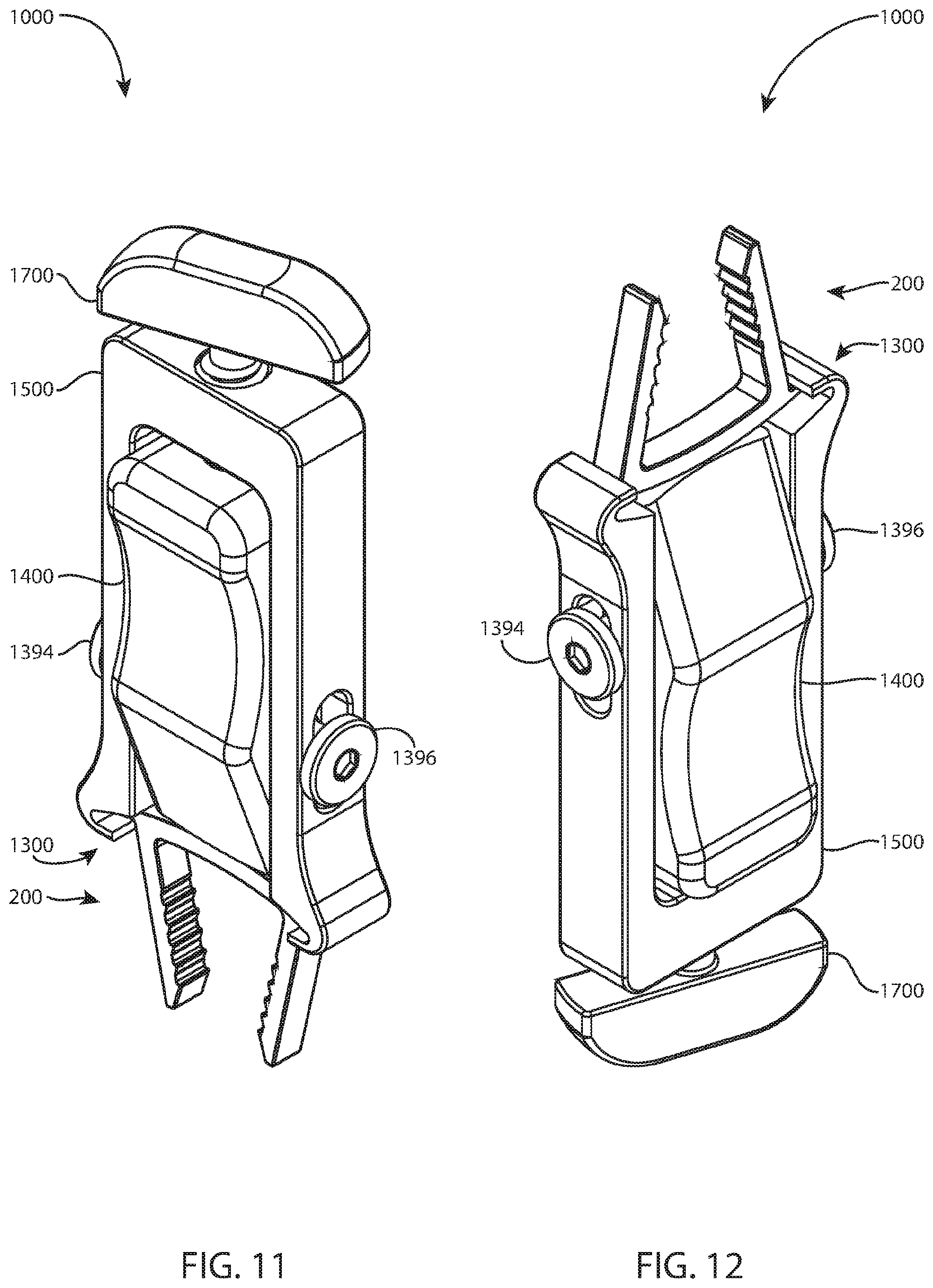
[0055] Referring to FIGS. 11 and 12, another implant delivery system 1000 includes the implant 200 and another inserter 1300. FIG. 17 illustrates the system 1000 with the implant 200 coupled to the inserter 1300, the implant 200 in a free state. FIG. 18 illustrates the system 1000 with the implant 200 coupled to the inserter 1300, the implant 200 in an elastically deformed state.
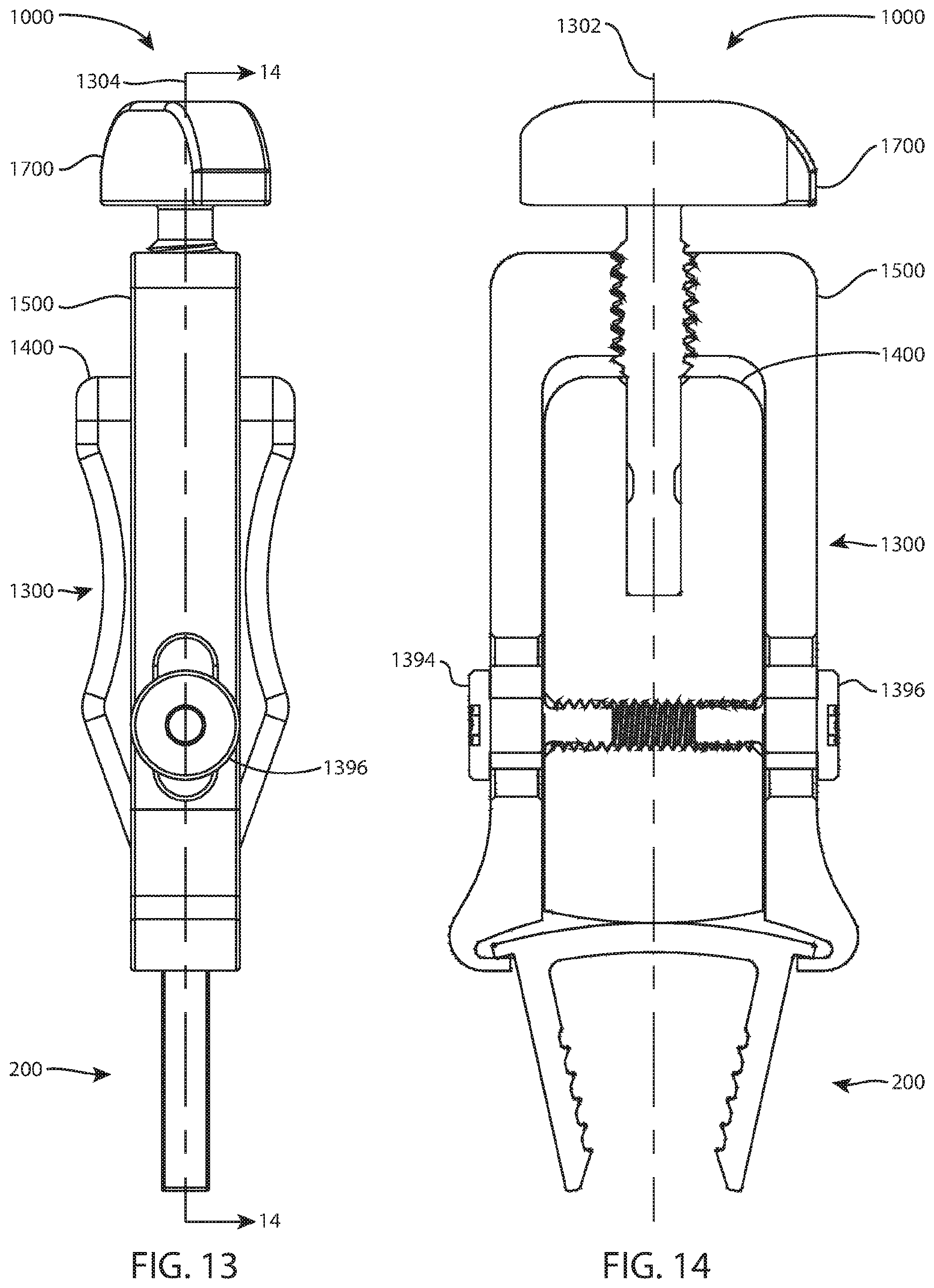
[0056] Referring to FIGS. 11-18, the inserter 1300 may include a body 1400, a jaw member 1500, a knob 1700, a left screw 1394, a right screw 1396, a front pin 1390, and a rear pin 1392.
[0057] The illustrated inserter 1300 may have a first plane of symmetry along plane 1302 of FIG. 14, which is shown edge on and is thus represented by a line 1302, and may have a second plane of symmetry along plane 1304 of FIG. 13, which is shown edge on and is thus represented by section line 14-14. The first plane of symmetry divides the inserter 1300 into identical left and right halves. The first plane of symmetry is also shown in FIGS. 17 and 18. The second plane of symmetry divides the inserter 1300 into identical front and back halves. The first and second planes of symmetry are perpendicular to each other. The first and second planes of symmetry may also apply to the implant 200, the body 1400, the jaw member 1500, and the knob 1700. However, in other examples, the inserter 1300 and/or implant 200 may have only one plane of symmetry, or no plane of symmetry so that they are asymmetric.
[0058] The body 1400 is an elongated part that extends between a distal end 1402 and an opposite proximal end 1404. The distal end 1402 may be referred to as a working portion. The body 1400 has a front surface 1406, an opposite back surface 1408, a left side 1410, and an opposite right side 1412. A central longitudinal hole 1414 extends into the body 1400 from the proximal end 1404. A distal aspect 1416 of the distal end 1402 may be convex in the front or back view, as seen in FIGS. 14, 17, and 18, and may be straight in the side view. A threaded hole 1418 extends through the body 1400 between the left and right sides 1410, 1412 proximal to the distal aspect 1416. Front and rear holes 1420, 1422 extend through the body 1400 between the left and right sides 1410, 1412 proximal to the threaded hole 1418. The holes 1420, 1422 intersect the front and rear sides, respectively, of the central longitudinal hole 1414.
[0059] The jaw member 1500 includes a central body 1502 with left and right arms 1504, 1506. The body 1502 in this example may be rectangular, may be continuous with the arms 1504, 1506, and may include central longitudinal internal threads 1508. Other examples may lack internal threads. The left arm 1504 extends laterally from the body 1502, bends distally at a left elbow 1510, extends distally, and terminates in a left hook 1512 that cups toward the right arm 1506. The right arm 1506 extends laterally from the body 1502, bends distally at a right elbow 1514, extends distally, and terminates in a right hook 1516 that cups toward the left arm 1504. The right arm 1506 may optionally be a mirror image of the left arm 1504, as shown in this example. The hooks 1512, 1516 may be replaced with other connection features that correspond to the particular connecting means of the implant 200, for example the hooks may be replaced with couplings that engage the front-to-back connecting means mentioned above. A longitudinal slot 1518 may extend through the left arm 1504 from left to right and another longitudinal slot 1520 may extend through the right arm 1506 from left to right. The slots 1518, 1520 may be aligned to form a single slot extending from left to right through the jaw member 1500 proximal to the hooks 1512, 1516 and distal to the elbows 1510, 1514.
[0060] The knob 1700 extends between a distal end 1702 and an opposite proximal end 1704. The knob 1700 has a front surface 1706 and an opposite back surface 1708. The distal end 1702 includes a distally-extending shaft 1710 with a proximal externally threaded portion 1712 and a distal smooth portion 1714. A circumferential groove 1716 extends around the smooth portion 1714 about halfway along its proximal-distal length. The externally threaded portion 1712 threadedly engages the internal threads 1508 of the jaw member 1500. The proximal end 1704 is laterally enlarged relative to the shaft 1710, forming a T-handle.
[0061] When the inserter 1300 is fully assembled (operatively assembled), the body 1400 is received between the left and right arms 1504, 1506 of the jaw member 1500. The proximal end 1404 faces the central body 1502 and the distal end 1402 is near the hooks 1512, 1516. The shaft 1710 of the knob 1700 extends distally through the internal threads 1508 of the jaw member 1500 and into the central longitudinal hole 1414 of the body. The externally threaded portion 1712 of the shaft 1710 threads into engagement with the internal threads 1508 and the smooth portion 1714 is received in the hole 1414. The circumferential groove 1716 is aligned with the holes 1420, 1422, and the pins 1390, 1392 are received in the holes 1420, 1422, respectively, and in the groove 1716 to couple the knob 1700 to the body 1400 in a fixed axial (proximal-distal) relationship, while leaving the knob free to rotate relative to the body. Optionally, the left and/or right arms 1504, 1506 may include access windows (not shown) that align with the holes 1420, 1422 so that the pins 1390, 1392 can be inserted in the holes 1420, 1422. Optionally, the pins 1390, 1392 and holes 1420, 1422 may be oriented front-to-back instead of left-to-right as shown. The left screw 1394 extends through the slot 1518 and threads into the hole 1418 from the left. The right 1396 extends through the slot 1520 and threads into the hole 1418 from the right.
[0062] A method of assembling the inserter 1300 may include any or all of the following steps in any order: inserting the body 1400 between the left and right arms 1504, 1506 of the jaw member 1500; inserting the shaft 1710 of the knob 1700 through the internal threads 1508 of the jaw member and into the central longitudinal hole 1414 of the body; threading the externally threaded portion 1712 of the shaft into engagement with the internal threads 1508; positioning the circumferential groove 1716 adjacent to the holes 1420, 1422 of the body; inserting the pins 1390, 1396 into the holes 1420, 1422, respectively, and in the groove 1716; inserting the left screw 1394 through the slot 1518 of the jaw member and threading the left screw 1394 into the threaded hole 1418 of the body; and inserting the right screw 1396 through the slot 1520 and threading the right screw 1396 into the threaded hole 1418.
[0063] When the inserter 1300 is fully assembled, the knob 1700 is unable to translate proximal-distal relative to the body 1400 due to the pins 1390, 1392 in the holes 1420, 1422. However, the knob 1700 is free to rotate about the central longitudinal axis of the shaft 1710 relative to the body 1400. The knob 1700 is in threaded engagement with the jaw member 1500 and is therefore able to rotate and simultaneously move proximal-distal relative to the jaw member. Clockwise rotation of the knob 1700 causes the jaw member 1500 to move proximally relative to the body 1400; counterclockwise rotation of the knob causes the jaw member to move distally relative to the body. The distal aspect 1416 of the body 1400 and the upper surface 208 of the bridge 206 of the implant 200 may remain in contact when the jaw member 500 moves proximally.
[0064] When the implant 200 and the inserter 1300 are fully assembled (operatively assembled), the distal aspect 1416 of the body 1400 may be adjacent to, or may contact, the upper surface 208 of the bridge 206, the hooks 1512, 1516 engage under the connecting means 214, 216, and the bone engaging members 202, 204 extend distally from the inserter 200. Proximal surfaces 1513, 1517 of the hooks 1512, 1516 may engage the lower surfaces 218, 220 of the connecting means 214, 216. The implant 200 and the inserter 1300 may be fully assembled with the implant 200 in the free state; the three points of contact (distal aspect 1416 and hooks 1512, 1516) acting on the bridge 206 and connecting means 214, 216 may exert loads that are below the threshold for elastic or plastic deflection or deformation of the implant 200. The inserter 1300 supports and constrains the implant 200 from the left and right, and top and bottom (lower surfaces 218, 220). Referring to FIGS. 12 and 14, the entire inserter 1300 is proximal to the lower surface 210 of the bridge 206.
[0065] A method of assembling the implant 200 and the inserter 1300 may include any or all of the following steps in any order: rotating the knob 1700 counterclockwise; moving the jaw member 1500 distally relative to the body 1400; extending the hooks 1512, 1516 distally beyond the distal end 1402 of the body 1400, preferably far enough to provide clearance for the bridge 206 of the implant 200 distal to the body 1400; aligning the bridge 206 of the implant 200 parallel to the distal aspect 1416; sliding the hooks 1512, 1516 under the connecting means 214, 216 from the front or back; rotating the knob 1700 clockwise; moving the jaw member 1500 proximally relative to the body 1400; and contacting the bridge 206 with the distal aspect 1416. Alternatively, the bridge 206 may be aligned transverse to the distal aspect 1416 and the implant 200 rotated relative to the inserter 1300 so that the connecting means 214, 216 rotate into engagement with the hooks 1512, 1516.
[0066] The inserter 1300 may be disconnected from the implant 200 at least by reversing the assembly steps.
[0067] When the implant 200 and the inserter 1300 are operatively assembled, the inserter 1300 may be actuated to move the implant 200 between the free state and an elastically deformed state. Referring to FIG. 14, clockwise rotation of the knob 1700 causes the jaw member 1500 to move proximally relative to the body 1400, causing the hooks 1512, 1516 to pull proximally on the connecting means 214, 216 against the static resistance or support of the distal aspect 1416 or other static support feature(s). This causes the bridge 206 to elastically deform in three point bending, which causes the bone engaging members 202, 204 to spread apart. Counterclockwise rotation of the knob 1700 causes the jaw member 1500 to move distally relative to the body 1400, reducing the proximal force of the hooks 1512, 1516 on the connecting means 214, 216. This allows the implant 200 to relax toward the free state.
[0068] A surgical method for stabilizing first and second bone fragments may include any or all of the following steps in any order: assembling the inserter 1300; assembling the implant 200 and the inserter 200; actuating the inserter 200; moving the jaw member 1500 proximally relative to the body 1400; moving the implant 200 from the free state to an elastically deformed state; moving the bone engaging members 202, 204 from a distally-converging state to a parallel state; creating a first hole in a first bone fragment; creating a second hole in a second bone fragment; inserting the left bone engaging member 202 in the first hole; inserting the right bone engaging member 204 in the second hole; seating the lower surface 210 against a surface of the first or second bone fragment; releasing the inserter 1300; moving the jaw member 1500 distally relative to the body 1400; moving the implant 200 from the elastically deformed state toward the free state; moving the bone engaging members 202, 204 from a parallel state toward a distally-converging state; and disconnecting the inserter 1300 from the implant 200.
[0069] Any methods disclosed herein include one or more steps or actions for performing the described method. The method steps and/or actions may be interchanged with one another. In other words, unless a specific order of steps or actions is required for proper operation of the embodiment, the order and/or use of specific steps and/or actions may be modified.
[0070] Reference throughout this specification to "an embodiment" or "the embodiment" means that a particular feature, structure or characteristic described in connection with that embodiment is included in at least one embodiment. Thus, the quoted phrases, or variations thereof, as recited throughout this specification are not necessarily all referring to the same embodiment.
[0071] Similarly, it should be appreciated that in the above description of embodiments, various features are sometimes grouped together in a single embodiment, Figure, or description thereof for the purpose of streamlining the disclosure. This method of disclosure, however, is not to be interpreted as reflecting an intention that any claim require more features than those expressly recited in that claim. Rather, as the following claims reflect, inventive aspects lie in a combination of fewer than all features of any single foregoing disclosed embodiment. Thus, the claims following this Detailed Description are hereby expressly incorporated into this Detailed Description, with each claim standing on its own as a separate embodiment. This disclosure includes all permutations of the independent claims with their dependent claims.
[0072] Recitation in the claims of the term "first" with respect to a feature or element does not necessarily imply the existence of a second or additional such feature or element. Elements recited in means-plus-function format are intended to be construed in accordance with 35 U.S.C. .sctn. 112 Para. 6. It will be apparent to those having skill in the art that changes may be made to the details of the above-described embodiments without departing from the underlying principles of the technology.
[0073] While specific embodiments and applications of the present technology have been illustrated and described, it is to be understood that the technology is not limited to the precise configuration and components disclosed herein. Various modifications, changes, and variations which will be apparent to those skilled in the art may be made in the arrangement, operation, and details of the methods and systems of the present technology disclosed herein without departing from the spirit and scope of the technology.
* * * * *
D00000
D00001
D00002
D00003
D00004
D00005
D00006
D00007
D00008
D00009
D00010
D00011
D00012

XML
uspto.report is an independent third-party trademark research tool that is not affiliated, endorsed, or sponsored by the United States Patent and Trademark Office (USPTO) or any other governmental organization. The information provided by uspto.report is based on publicly available data at the time of writing and is intended for informational purposes only.
While we strive to provide accurate and up-to-date information, we do not guarantee the accuracy, completeness, reliability, or suitability of the information displayed on this site. The use of this site is at your own risk. Any reliance you place on such information is therefore strictly at your own risk.
All official trademark data, including owner information, should be verified by visiting the official USPTO website at www.uspto.gov. This site is not intended to replace professional legal advice and should not be used as a substitute for consulting with a legal professional who is knowledgeable about trademark law.