Medical Gown
Ponich; David Randall ; et al.
U.S. patent application number 16/448402 was filed with the patent office on 2020-01-09 for medical gown. The applicant listed for this patent is priMED Medical Products Inc.. Invention is credited to Lucas Paul Ethier, Joshua Alfred Eulert, Enrico Wing Kei Fok, David Randall Ponich.
| Application Number | 20200008499 16/448402 |
| Document ID | / |
| Family ID | 69102473 |
| Filed Date | 2020-01-09 |


| United States Patent Application | 20200008499 |
| Kind Code | A1 |
| Ponich; David Randall ; et al. | January 9, 2020 |
Medical Gown
Abstract
A gown is provided including non-woven fabric having a front portion, a rear portion, said rear portion ending in a lower edge, and a head insertion aperture that is between the front portion and the rear portion. The gown includes an opening in the rear portion; this opening is formed at the lower edge and extends upwards towards the head insertion aperture, and is configured to assist the wearing in donning the gown. There is a bridge extending across the rear portion at least partially between the opening and the head insertion aperture. This bridge is configured to tear and split the rear portion when the front portion is pulled away from the wearer.
| Inventors: | Ponich; David Randall; (Edmonton, CA) ; Eulert; Joshua Alfred; (Edmonton, CA) ; Fok; Enrico Wing Kei; (Edmonton, CA) ; Ethier; Lucas Paul; (Edmonton, CA) | ||||||||||
| Applicant: |
|
||||||||||
|---|---|---|---|---|---|---|---|---|---|---|---|
| Family ID: | 69102473 | ||||||||||
| Appl. No.: | 16/448402 | ||||||||||
| Filed: | June 21, 2019 |
Related U.S. Patent Documents
| Application Number | Filing Date | Patent Number | ||
|---|---|---|---|---|
| 62694821 | Jul 6, 2018 | |||
| Current U.S. Class: | 1/1 |
| Current CPC Class: | A41D 13/1236 20130101; A41D 13/1209 20130101; A41D 13/1245 20130101; A41D 2400/52 20130101; A41D 13/129 20130101 |
| International Class: | A41D 13/12 20060101 A41D013/12 |
Claims
1. A gown comprising: a. a non-woven fabric having a front portion, a rear portion, the rear portion ending in a lower edge, and a head insertion aperture defined between the front portion and the rear portion; b. an opening, the opening defined in the rear portion, said opening formed at the lower edge and extending towards the head insertion aperture, configured to assist a wearer in donning the gown; and c. a bridge extending across the rear portion at least partially between the opening and head insertion aperture; the bridge being configured to tear and split the rear portion when the front portion is pulled away from the wearer.
2. The gown of claim 1, further comprising one or more notches, each notch extending from the head insertion aperture into the bridge; the one or more notches being configured to tear and split the bridge when the front portion is pulled away from the wearer.
3. The gown of claim 1, further comprising one or more notches, each notch extending from the opening into the bridge; the one or more notches being configured to tear and split the bridge when the front portion is pulled away from the wearer.
4. The gown of claim 2, further comprising one or more notches, each notch extending from the opening into the bridge; the one or more notches being configured to tear and split the bridge when the front portion is pulled away from the wearer.
5. The gown of claim 1, further comprising sleeves.
6. The gown of claim 5, wherein the sleeves terminate with a thumb loop configured to engage a base of a thumb of the wearer.
7. The gown of claim 5, wherein the sleeves terminate with an elasticized cuff to engage a wrist of the wearer.
8. The gown of claim 1, wherein the bridge, when measured from the head insertion aperture to the opening, is between 5 cm-10 cm in length.
9. The gown of claim 1, further comprising one or more tie members.
10. The gown of claim 1, wherein the length of the front portion is greater than the length of the rear portion.
11. The gown of claim 1, wherein the length of the front portion is equal to the length of the rear portion.
12. The gown of claim 2, wherein the notch is selected from a group consisting of a triangle, a diamond and a line.
13. The gown of claim 3, wherein the notch is selected from a group consisting of a triangle, a diamond and a line.
14. A method of wearing and removing a gown, said method comprising the steps of: a. accessing the gown, the gown comprising: a non-woven fabric having a front portion, a rear portion, said rear portion ending in a lower edge, and a head insertion aperture defined between the front portion and the rear portion; an opening, the opening defined in the rear portion, said opening slip formed at the lower edge and extending towards the head insertion aperture, configured to assist a wearer in donning the gown; and a bridge extending across the rear portion at least partially between the opening and head insertion aperture; the bridge being configured to tear and split the rear portion when the front portion is pulled away from the wearer; b. passing a head of a wearer through the head insertion aperture to don the gown; c. pulling the front portion away from the wearer, thereby tearing the bridge and splitting the non-woven fabric layer between the head insertion aperture and the opening to remove the gown.
15. The method of claim 14, wherein the gown further comprises one or more notches, each extending from the head insertion aperture into the bridge; the one or more notches being configured to tear and split the rear portion when the front portion is pulled away from the wearer.
16. The method of claim 14, wherein the gown further comprises one or more notches, each extending from the opening into the bridge; the one or more notches being configured to tear and split the rear portion when the front portion is pulled away from the wearer.
17. A method of making a gown, said method comprising the steps of: a. layering a plurality of non-woven fabrics to form multiple layers of the non-woven fabric; each having a top edge, a bottom edge, and two opposing side edges; b. cutting into the multiple layers of non-woven fabric a head insertion aperture between the top edge and the bottom edge between the two opposing side edges and an opening parallel to the side edges from the bottom edge to a point short of the head insertion aperture, thereby defining a bridge; c. separating the one or more layers of cut non-woven fabric; d. folding each cut non-woven fabric along a first line parallel to the top edge, the first line extending across the non-woven fabric through the head insertion aperture thereby defining a front portion and a rear portion; and e. attaching the front portion and the rear potion along at least a part of the outside edges.
18. The method of claim 17, further comprising cutting into the one or more layers of non-woven fabric one or more notches, each notch extending from the head insertion aperture into the bridge; the one or more notches being configured to tear and split the rear portion when the front portion is pulled away from the wearer.
19. The method of claim 17, further comprising cutting into the one or more layer of non-woven fabric one or more notches, each notch extending from the opening into the bridge; the one or more notches being configured to tear and split the rear portion when the front portion is pulled away from the wearer.
20. The method of claim 17, further comprising the step of cutting into the one or more layers of non-woven fabric a sleeve with a top edge, a bottom edge, and two opposing side edges.
Description
FIELD OF INVENTION
[0001] This invention relates generally to medical gowns and more specifically tear-off and disposable medical gowns.
BACKGROUND OF THE INVENTION
[0002] Medical gowns are commonly used in hospitals, clinics, and other medical facilities, where they are worn by patients and staff at medical facilities. Medical gowns are used for their protective function to protect the wearer from contact with germs and other microscopic items and to limit the transmission of germs, bodily fluids and microscopic items in the medical facility. In addition, medical gowns can serve a privacy function when used by patients to cover their bodies during procedures which require the patient to disrobe.
[0003] One issue with the prior art medical gowns is that they can be difficult to remove. Users of hospital gowns often aim to remove the gown using minimum contact to the gown thereby reducing the spread of germs and other microscopic items between the medical gown and the user.
[0004] Another issue with the prior art medical gowns is that they require the user to raise the gown above the user's head during doffing which risks germs and other microscopic items coming into contact with the wearer or surroundings.
[0005] Some designs have used complicated and difficult to manufacture perforations and scores to assist the wearing in removing the medical gown. Other designs have characteristics that are uncomfortable for some wearers.
[0006] For example, US Patent Application Publication No. US 2013/0276203 teaches a gown that requires perforations to be made in the gown to assist the wearer with removing the gown.
[0007] As another example, US Patent Application Publication No. US 2014/0007316 teaches a gown wherein the neck line contains a round or crew cut on one side and a pointed or "v" cut on the other side which is complicated to manufacture and less comfortable for the wearer.
[0008] It would be advantageous to have an improved gown that is easy to remove and simple to manufacture.
SUMMARY
[0009] The present invention firstly provides for a gown comprising non-woven fabric having a front portion, a rear portion, a lower edge, and a head insertion aperture that is between the front portion and the rear portion. The gown comprises an opening in the rear portion; this opening is formed at the lower edge and extends upwards towards the head insertion aperture, and is configured to assist the wearing in donning the gown. There is a bridge extending across the rear portion at least partially between the opening and the head insertion aperture. This bridge is being configured to tear and split the rear portion when the front portion is pulled away from the wearer.
[0010] The present invention secondly provides for a method of wearing and removing a gown, comprising a number of steps.
[0011] In the first step, the wearer accesses the gown comprising non-woven fabric having a front portion, a rear portion, a lower edge, and a head insertion aperture that is between the front portion and the rear portion. The gown comprises an opening in the rear portion; this opening is formed at the lower edge and extends upwards towards the head insertion aperture, and is configured to assist the wearing in donning the gown. There is a bridge extending across the rear portion at least partially between the opening and the head insertion aperture. This bridge is being configured to tear and split the rear portion when the front portion is pulled away from the wearer.
[0012] Next, the wearer passes their head through the head insertion aperture to don the gown. To remove the gown, the wearer pulls the front portion of the non-woven fabric layer, thereby tearing the bridge and splitting the rear portion of the non-woven fabric layer between the head insertion aperture and the opening to remove the gown.
[0013] The present invention secondly provides for a method of making the gown, comprising a number of steps.
[0014] The first step provides for one or more non-woven fabrics each are having a top edge, a bottom edge, and two opposing side edges and then layering the one or more non-woven fabrics to form multiple layers of the non-woven fabric. The layers of the one or more non-woven fabrics are then cut to provide a head insertion aperture between the top edge and the bottom edge between the two opposing side edges and an opening parallel to the side edges from the bottom edge to a point short of the head insertion aperture, thereby defining a bridge.
[0015] Next, the one or more layers of cut non-woven fabric are separated. Each individual layer of cut non-woven fabric is folded along a first line parallel to the top edge, the first line extending across the non-woven fabric through the head insertion aperture thereby defining a front portion and a rear portion. After the layers of cut non-woven fabric are folded, the front portion and the rear portion are then attached along at least a part of the outside edge.
[0016] It is to be understood that other aspects of the present invention will become readily apparent to those skilled in the art from the following detailed description, wherein various embodiments of the invention are shown and described by way of illustration. As will be realized, the invention is capable for other and different embodiments and its several details are capable of modification in various other respects, all without departing from the spirit and scope of the present invention. Accordingly the drawings and detailed description are to be regarded as illustrative in nature and not as restrictive.
BRIEF DESCRIPTION OF THE DRAWINGS
[0017] A further, detailed, description of the invention, briefly described above, will follow by reference to the following drawings of specific embodiments of the invention. The drawings depict only typical embodiments of the invention and are therefore not to be considered limiting of its scope. In the drawings:
[0018] FIG. 1 is a front elevation view of one example of a gown in accordance with one or more embodiments of the invention;
[0019] FIG. 2 is a rear elevation view of one example of the gown of FIG. 1;
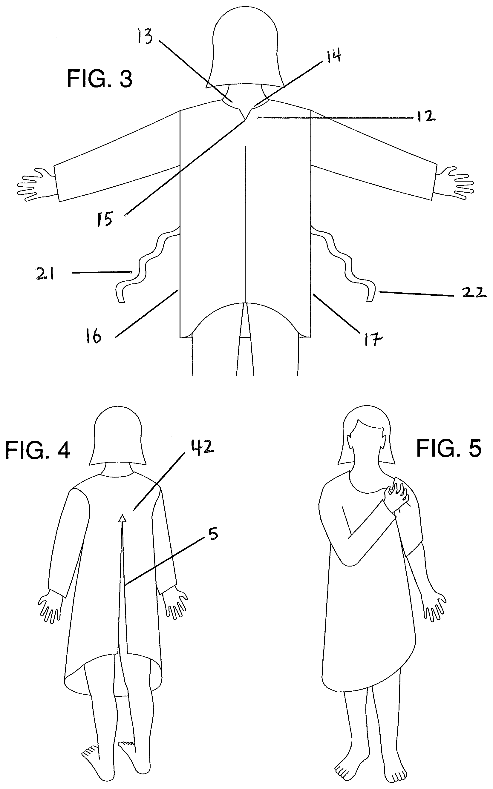
[0020] FIG. 3 is a rear elevation view of another example of a gown of the present invention, containing a notch and tie members configured in accordance with one or more embodiments of the invention;
[0021] FIG. 4 is rear perspective view of a user wearing an example of a gown containing a notch configured in accordance with one or more embodiments of the invention;
[0022] FIG. 5 is a front perspective view of a user removing another example of a gown in accordance with one or more embodiments of the invention;
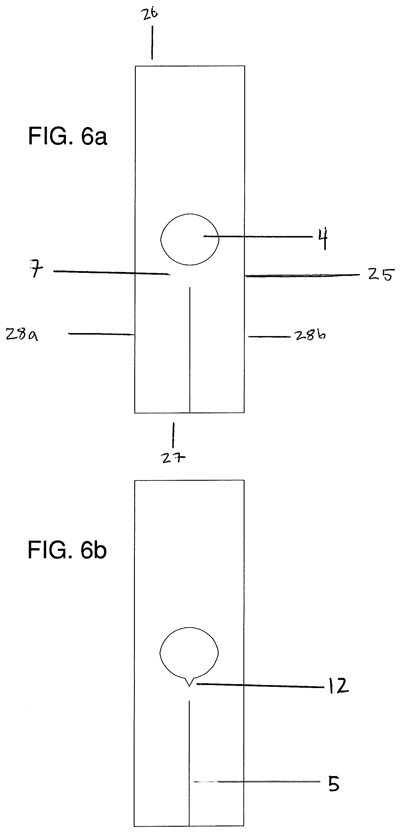
[0023] FIG. 6(a) is a plan view of one example of one or more embodiments of a method of making the invention.
[0024] FIG. 6(b) is a plan view of one example of one or more embodiments of a method of making the invention; and
[0025] FIG. 7 is a close up view of the rear portion of the head insertion aperture with alternative notch.
[0026] The drawing is not necessarily to scale and in some instances proportions may have been exaggerated in order more clearly to depict certain features.
DETAILED DESCRIPTION OF VARIOUS EMBODIMENTS
[0027] The description that follows and the embodiments described therein are provided by way of illustration of an example, or examples, of particular embodiments of the principles of various aspects of the present invention. These examples are provided for the purposes of explanation, and not of limitation, of those principles and of the invention in its various aspects.
[0028] With reference to the FIGS. (1), (2), (3) and (4), the present invention relates to a new and useful medical gown (1). The present invention is designed to overcome difficulties in removing medical gowns and complexities involved in manufacturing medical gowns.
[0029] While the present invention is described as a medical gown, this invention could be any number of gowns and is not necessarily confined to medical applications, and thus any references to a medical gown include garments, apparel, cover gowns, surgical gowns, surgical isolation gowns, front protection gowns or other gowns. More preferably, the garments related to the present invention are medical gowns such as surgical or isolation gowns.
[0030] While the present description may refer to such medical gowns and accessories and parts thereof, it would be understood by a person of skill in the art that the present invention can be applied to any number of other garments or fabric in general without departing from the scope of the invention.
[0031] The present invention provides for a medical gown (1) comprised of non-woven fabric. The medical gown (1) having a front portion (2) and a rear portion (3) with a head insertion aperture (4) and a lower opening (23). The lower opening being defined by the front portion (2) and rear portion (3) lower edges.
[0032] In one embodiment, the length of the front portion (2) is equal to the length of the rear portion (3). In another embodiment, the length of the front portion (2) varies from the length of the rear portion (3) and is preferably greater in length than the rear portion.
[0033] In one embodiment, the head insertion aperture (4) is comprised of curved edges on the front portion (2) and the rear portion (3). In another embodiment, the head insertion aperture (4) is comprised of straight edges on the front portion (2) and the rear portion (3). Optionally, the head insertion aperture (4) contains elastic configured to engage the neck of the wearer and hold the medical gown (1) close to the neck of the wearer. In other embodiments, the head insertion aperture may be cinched tighter with ties, which ties may be elastic or otherwise, or other methods readily apparent to those skilled in the art.
[0034] The rear portion (3) of the medical gown (1) preferably comprises an opening (5). In one embodiment, the opening (5) comprises a slit. Preferably, the opening is formed into the rear portion (3) starting from a lower rear edge (6) to a point short of the head insertion aperture (4) on the rear portion (3). In a preferred embodiment, the opening (5) is a straight line along the rear portion (3) of the medical gown (1). In another embodiment the opening (5) runs perpendicular to the lower rear edge (6). Optionally, the opening (5) runs along the centre of the rear portion (3) of the medical gown (1). In another option, the opening (5) is formed directly below but separate from the lowest point of an overall head insertion aperture (4). In one embodiment, the opening (5) is an opening where the opening is formed into the rear portion (3) starting from a lower rear edge (6) to a point short of the head insertion aperture (4) on the rear potion (3). The width of the opening can range from greater than 0 cm to span the entire rear portion (3). Where the opening spans the rear portion (3), the rear portion is defined as the bridge.
[0035] Between the opening (5) and the head insertion aperture (4) is a bridge (7). The bridge (7) can be defined as the piece of non-woven fabric between the head insertion aperture (4) and the opening (5). The bridge (7) is configured to tear and split the rear portion (3) when the front portion (2) is pulled away from the wearer. Preferably, the bridge (7) when measured from the head insertion aperture (4) to the opening (5) is between 5-10 cm. More preferably, the bridge (7) is comprised of non-woven fabric that when measured from the lowest point of the curved head insertion aperture to the opening (5) is 5 cm. The bridge (7) is comprised of either continuous fabric or separate fabric attached to the rear portion (3). Optionally, the bridge is comprised of the same fabric of the gown or a different fabric than that fabric which comprises the gown. In one embodiment, the bridge (7) takes the configuration of a yoke.
[0036] The bridge (7), where included, provides several functions. In one illustrative example, when the wearer pulls the medical gown (1) away from her torso, this causes the force of the pull motion to focus on the bridge (7) causing the non-woven fabric to tear from the opening (5) through the bridge (7). The combination of the tensile strength of the non-woven fabric that comprises the bridge (7) and the width of the bridge (7) provides a bridge (7) strong enough to support the medical gown (1) when the user is donning and wearing the gown and weak enough to allow the user to easily tear and remove the gown. In addition, the width of the bridge (7) is designed to ensure that the bridge (7) tears predictably when force is applied to the medical gown (1).
[0037] More specifically, the bridge (7) can be torn by the wearer without the need for perforations or scores. In another illustrative example, the bridge (7) provides more privacy to the wearer than a "v" neck cutline in the rear portion (3) otherwise would, allowing the wearer's back to be covered by the bridge (7). In addition, and as a further example, in one embodiment the bridge (7) and the head insertion aperture (4) are curved, providing a round neck cutline into the medical gown (1) on the front portion (2) and the rear portion (3), and this is more comfortable to the wearer than "v" neck cutline in the rear portion (3). In a further example, the bridge (7) and the insertion aperture (4) that are configured to ensure the gown rests on the neck and shoulders of the wearer evenly without "drooping" or "sagging" towards the front portion (2) exposing the chest of the wearer.
[0038] In another embodiment, the rear portion (3) head insertion aperture (4) comprises one more notches (12) preferably extending from the head insertion aperture (4) into the bridge (7). The one or more notches (12) are preferably cut in a "v" shape comprised of a left point (13) and right point (14) and bottom point (15). In a preferred embodiment, the angle formed between the left point (13), the bottom point (15), and the right point (14) is greater than zero degrees. In another embodiment, the angle formed between the left point (13), the bottom point (15), and the right point (14) is between 1 degree and 115 degrees. In a preferred embodiment, the angle formed between the left point (13), the bottom point (15), and the right point (14) is acute. Optionally, the angle formed between the left point (13), the bottom point (15), and the right point (14) is ninety degrees. It would be understood that the one or more notches (12) can take other shapes, such as a diamond shape as shown in FIG. 7 or a line.
[0039] In another option, the distance from the left point (13) and the bottom point (15) is the same as the distance from the right point (14) and the bottom point (15). In another option, the distance from the left point (13) and the bottom point (15) is different than the distance from the right point (15) and the bottom point (15). In another option, the distance from the left point (13) and the bottom point (15) and distance from the right point (15) and the bottom point (15) are each between about 1-5 cm. In the preferred embodiment, the distance between the right point (15) and the left point (13) is greater than 0.5 cm. In another option, the distance between the left point (13) and the right point (14) is 1 cm. Most preferably, there is only one notch (12) and it is centered so the bottom point (15) aligns with the opening (5).
[0040] The one or more notches (12), where included, provide several functions. In one illustrative example, when the wearer pulls the medical gown (1) away from her torso, this causes the force of the pull motion to focus on the bottom point (15) of the one or more notches (12) making it easier for the non-woven fabric to tear from the bottom point (15) and through the bridge (7). In another illustrative example, the one or more notches (12) provide more privacy to the wearer than a "v" neck cutline in the rear portion (3) otherwise would, allowing the wearer's back to be covered by the bridge (7). In addition, and as a further example, in one embodiment the one or more notches (12) cut into the head insertion aperture (4) that is in round shape providing a round or "crew neck" cutline into the medical gown (1), is more comfortable to the wearer than "v" neck cutline in the rear portion (3). In a further example the one or more notches (12) cut into the head insertion aperture (4) is configured to ensure the gown rests on the neck and shoulders of the wearer evenly without "drooping" or "sagging" towards the front portion (2) exposing the chest of the wearer.
[0041] In another embodiment, and as shown in FIGS. 4 and 7, the opening (5) comprises a second notch (42) preferably extending from the opening (5) into the bridge (7). In one embodiment, as illustrated in FIG. 4, the second notch (42) is in the shape of a triangle. The second notch (42), in one other option as depicted in FIG. 7, is cut in a "diamond" shape comprising of a second left point (43), a second right point (45), a second bottom point (47), and a top point (48). In a preferred embodiment, the angle formed between the second left point (43), the second bottom point (47), and the second right point (45) is greater than zero degrees. In another embodiment, the angle formed between the second left point (43), the second right bottom point (47), and the second right point (45) is between 1 and 115 degrees. In a preferred embodiment, the angle formed between the second left point (43), the second bottom point (47), and the second right point (45) is acute. Optionally, the angle formed between second left point (43), the second bottom point (47), and the second right point (45) is ninety degrees.
[0042] In another option, the distance from the second left point (43) and the second bottom point (47) is the same as the distance from the second right point (45) and the second bottom point (47). In another option, the distance from the second left point (43) and the second bottom point (47) is different than the distance from the second right point (45) and the second bottom point (47). In another option, the distance from the second left point (43) and the second bottom point (47) and distance from the second right point (45) and the second bottom point (47) are each between about 1-5 cm. In the preferred embodiment, the length of the opening between the second right point (45) and the second left point (43) is greater than 0.5 cm. In another option, the length of the opening between the second left point (43) and the second right point (45) is 1 cm. Most preferably, there is only one second notch (43) on the opening (5) and it is centered at the point of the opening closest to the head insertion aperture and aligns with the opening (5). It is understood that to those skilled in the art that the second notch (42) could comprise a number of shapes, including a diamond shape as demonstrated in FIG. 7, a triangle as shown in FIG. 4, or a line.
[0043] The second notch (42), where included, provides several functions. In one illustrative example, when the wearer pulls the medical gown (1) away from her torso, this causes the force of the pull motion to focus on a top point (48) of the second notch (42) making it easier for the non-woven fabric to tear from the top point (48) through the land bridge (7).
[0044] In addition, and as a further example, in one embodiment of the second notch (42) cut into the opening (5), the head insertion aperture provides a "crew neck" cutline into the medical gown (1) that is more comfortable to the wearer than "v" neck cutline in the rear portion (3). In a further example of the second notch (42) cut into the opening (5), the head insertion aperture provides a "crew neck" cutline into the medical gown (1) that rests on the neck and shoulders of the wearer evenly without "drooping" or "sagging" towards the front portion (2).
[0045] Optionally, the medical gown (1) is configured to have a left sleeve (8) and a right sleeve (9) attached to the medical gown (1) with each sleeve comprising an arm insertion aperture. The left sleeve (8) and right sleeve (9) can be attached to medical gown (1) in a variety of ways. In another embodiment, the left sleeve (8) and right sleeve (9) are adhesively attached to the medical gown (1). In another embodiment, the left sleeve (8) and right sleeve (9) are thermally or ultrasonically bonded to the medical gown (1). In one embodiment, the left sleeve (8) and right sleeve (9) are sewn to the medical gown. Optionally, the non-woven fabric of gown is cut with sleeves integral to the front portion (1) and/or the rear portion (2). In other options the left sleeve (8) and the right sleeve (9) and gown body may be comprised of different materials.
[0046] In one embodiment, the left sleeve (8) and the right sleeve (9) contain a retention member to retain each sleeve along the arm of the wearer. Optionally, the retention member contains elastic configured to engage the wrist of the wearer and hold the medical gown (1) close to the wrist of the wearer.
[0047] In one option, the left sleeve (8) and the right sleeve (9) each terminate with a thumb loop (11) configured to engage the thumb of the wearer to hold each sleeve to the wrist of the wearer.
[0048] The thumb loops, where included, provide several functions. One illustrative function is that the thumb loops keep the sleeves (8)(9) pulled along the wearer's arms and prevent the sleeves (8)(9) from "riding up" and exposing the wearer's wrist or arm. Another illustrative function is that the thumb loops prevent twisting of the sleeves (8)(9) about the wearer's arm. Each thumb loop is configured, in one embodiment, to engage the saddle of a thumb of the wearer.
[0049] In other embodiments, the thumb loop (11) may be combined with a wrist elastic or a draw string and mechanism to maintain position around the wrist.
[0050] In another embodiment, one or more tie members (19) may be attached to the medical gown (1). The tie members (19) can be made from the same non-woven fabric as the medical gown (1). In one embodiment, the tie members include a first tie member (21) disposed on the left side (16) of the medical gown (1), and a second tie member (22) disposed on the right side (17) of the medical gown (1). Accordingly, one tie member (21) is disposed on one side of the opening (5), while the other tie member (22) is disposed on a second side of the opening (5).
[0051] In one embodiment, tie members (21) and (22) are a single tie member and that single tie member is attached to some point on the gown, preferably in the middle of the gown.
[0052] The tie member(s) (21)(22) can be attached to the medical gown (1) in a variety of ways. In one embodiment, the tie members (21)(22) are sewn to the medical gown (1). In another embodiment, the tie members (21)(22) are adhesively attached to the medical gown (1). In another embodiment, the tie members (21)(22) are thermally or ultrasonically bonded to the medical gown (1). Other attachment methods will be obvious to those of ordinary skill in the art.
[0053] In the illustration of one embodiment, FIG. (3), the time members (21)(22) are attached on a side medical gown (1). When the tie members (21)(22) are tied across the opening (5), the body of the medical gown (1) becomes cinched at the waist region of the wearer.
[0054] Optionally, the colour of the non-woven fabric is yellow however other colors may be preferred based on the end users practices. Optionally, the non-woven fabric is impregnated with a material that changes colour when exposed to liquid or other contaminants.
[0055] In one embodiment, to further assist the wearer in removing the gown, the non-woven fabric is configured so as to be tearable by a wearer. Thus, if a wearer were to grasp opposing sides of a section of the non-woven fabric, and then pull, the non-woven fabric would tear. As will be shown below, and in one embodiment, the wearer removes the medical gown by pulling the front potion of the gown, this action then tearing the non-woven fabric across the bridge (7).
[0056] Accordingly, a non-woven fabric that is easily torn by a wide range of strengths of wearers may be selected for construction of the medical gown (1) in accordance with such an embodiment.
[0057] Turning now to FIGS. 4 and 5, illustrated therein is a method of wearing and removing a medical gown (1) in accordance with one or more embodiments of the invention. FIG. 4 illustrates a wearer who has already donned the medical gown. In this illustrative embodiment, the medical gown (1) defines a head insertion aperture (4) between a front portion (2) and a rear portion (3). The rear portion (3) of the medical gown (1) contains an opening (5). The opening is cut into a lower rear portion (3) starting from the lower rear edge (6) to a point on the rear portion (3) short of the head insertion aperture (4). In the preferred embodiment, the opening (5) is cut in a straight line. In one embodiment, the opening (5) runs perpendicular to the lower rear edge (6). Between the opening (5) and the head insertion aperture (4) is a bridge (7). The bridge (7) can be defined as the piece of non-woven fabric between the head insertion aperture (4) and the opening (5). The bridge (7) is configured to tear and split the rear portion (3) when the front portion (2) is pulled away from the wearer. In another embodiment, the rear portion (3) head insertion aperture (4) comprises one more notches (12) preferably extending from the head insertion aperture (4) into the bridge (7). The one or more notches (12) are preferably cut in a "v" shape comprised of a left point (13) and right point (14) and bottom point (15). The medical gown (1) optionally includes one or more tie members (21)/(22) extending from the non-woven fabric layer. As shown in FIG. (4) the wearer has passed her head through the head insertion aperture and has optionally also tied the tie members (21)(22) about her torso.
[0058] Turning now to FIG. (5), the wearer is now removing the medical gown (1). Specifically, in this example she is using her left hand to grasp the front portion (2) of the medical gown (1). She then pulls medical gown (1) away from her torso. This causes the bridge (7) to tear, thereby splitting the rear portion (3) of the medical gown (1). This pulling action tears the bridge (7) and splits the bridge (7) between the head insertion aperture (4) and the opening (5). The wearer can now simply drop the medical gown (1) about her torso and step out of it or preferably, the user may roll the gown from the inside to avoid contact with the potentially contaminated outside surface of the gown and dispose of the rolled gown as waste. Where the tie members (21)/(22) are loosely tied, the pulling action can cause them to become untied, thereby facilitating simple removal of the medical gown (1) with a simple stroke.
[0059] In another embodiment, in which the head insertion aperture (4) has one or more notches (12), the wearer pulls the medical gown (1) away from her torso, this causes tensile force motion to focus on the bottom point (15) of the one or more notches (12) making it easier for the non-woven fabric to tear at the bottom point (15), thereby splitting the bridge (7) below the bottom point (15) and above the opening (5).
[0060] Turning now to FIG. 6 and the method of making the medical gown (1). The roll of non-woven fabric is cut into a rectangle (25) having a top edge (26), a bottom edge (27), and two opposing side edges (28(a)(b)), the rectangle (25) being placed on a flat table. Optionally, multiple rectangles (25) are placed on a flat table forming layers of rectangles (25) allowing for efficiencies in the method of making the medical gown (1) as more than one rectangle (25) can be prepared simultaneously.
[0061] Use of a cutting machine to punch into the rectangles (25) a head insertion aperture (4) therein between the top edge (26) and the bottom edge (27) between the two opposing side edges (28(a)(b)) and an opening (5) parallel to the opposing side edges (28(a)(b)) from the bottom edge (27) at least partially to a point on or below the top edge (26). Folding the medical gown (1) such that top edge (26) and the bottom edge (27) comprise a lower opening (23).
[0062] Then the two opposing side edges (28(a)(b)) are at least partially joined together with the use of an ultrasonic weld. Optionally, the two opposing side edges (28(a)(b)) can be sewn together.
[0063] Optionally, a second rectangle having a top edge, a bottom edge, and two opposing side edges is placed on a flat table and then manually cut to form a sleeve piece having a top edge, a bottom edge, a first sleeve side and a second sleeve side. Optionally, multiple rectangles are placed on a flat table forming layers of rectangles before the punch, allowing for efficiencies in the method of making the sleeves. In one embodiment, the length of the first sleeve side is greater than the length of the second sleeve side.
[0064] Optionally, the sleeve piece is placed below a cutting machine that punches into the sleeve piece a thump loop (11) near the second sleeve side configured to engage the thumb of the wearer to hold each sleeve to the wrist of the wearer. Optionally, sleeve pieces are placed on a flat table forming layers of rectangles before the cutting machine punches into the sleeve piece a thump loop to allow for efficiencies in the method of making the thumb loop. Optionally, elastic is sown across the sleeve piece at a point between the first edge and the thumb loop.
[0065] Optionally, the sleeve pieces are then joined to the medical gown (1) though the use of an ultrasonic weld along the opposing sides. Optionally, the sleeve pieces are sewn to the medical gown (1). Preferably, the first sleeve side is attached to the medical gown (1).
[0066] In one embodiment, the tie members (21)(22) are then joined to the medical gown (1) through the use of an ultrasonic weld. Optionally, the tie members (21)(22) are sewn to the medical gown (1).
[0067] All the offcuts of the non-woven fabric can optionally be collected and sent back to the supplier of the material to be melted down and recycled.
[0068] The previous description of the disclosed embodiments is provided to enable any person skilled in the art to make or use the present invention. Various modifications to those embodiments will be readily apparent to those skilled in the art, and the generic principles defined herein may be applied to other embodiments without departing from the spirit or scope of the invention. Thus, the present invention is not intended to be limited to the embodiments shown herein, but is to be accorded the full scope consistent with the claims, wherein reference to an element in the singular, such as by use of the article "a" or "an" is not intended to mean "one and only one" unless specifically so stated, but rather "one or more". All structural and functional equivalents to the elements of the various embodiments described throughout the disclosure that are known or later come to be known to those of ordinary skill in the art are intended to be encompassed by the elements of the claims. Moreover, nothing disclosed herein is intended to be dedicated to the public regardless of whether such disclosure is explicitly recited in the claims. No claim element is to be construed under the provisions of 35 USC 112, sixth paragraph, unless the element is expressly recited using the phrase "means for" or "step for".
* * * * *
D00000
D00001
D00002
D00003
D00004
XML
uspto.report is an independent third-party trademark research tool that is not affiliated, endorsed, or sponsored by the United States Patent and Trademark Office (USPTO) or any other governmental organization. The information provided by uspto.report is based on publicly available data at the time of writing and is intended for informational purposes only.
While we strive to provide accurate and up-to-date information, we do not guarantee the accuracy, completeness, reliability, or suitability of the information displayed on this site. The use of this site is at your own risk. Any reliance you place on such information is therefore strictly at your own risk.
All official trademark data, including owner information, should be verified by visiting the official USPTO website at www.uspto.gov. This site is not intended to replace professional legal advice and should not be used as a substitute for consulting with a legal professional who is knowledgeable about trademark law.