Compact Radar Switch/mimo Array Antenna With High Azimuth And Elevation Angular Resolution
ARKIND; Noam ; et al.
U.S. patent application number 16/480030 was filed with the patent office on 2020-01-02 for compact radar switch/mimo array antenna with high azimuth and elevation angular resolution. This patent application is currently assigned to ARBE Robotics Ltd. The applicant listed for this patent is ARBE ROBOTICS LTD. Invention is credited to Noam ARKIND, Amos BARON, Yoram STETTINER.
| Application Number | 20200003884 16/480030 |
| Document ID | / |
| Family ID | 63039430 |
| Filed Date | 2020-01-02 |


| United States Patent Application | 20200003884 |
| Kind Code | A1 |
| ARKIND; Noam ; et al. | January 2, 2020 |
COMPACT RADAR SWITCH/MIMO ARRAY ANTENNA WITH HIGH AZIMUTH AND ELEVATION ANGULAR RESOLUTION
Abstract
A method for increasing the effective aperture of radar switch/MIMO antenna array, using a low number of transmit (Tx) and receive (Rx) army elements, according to which an array of radar physical receive (Rx)/Transmit (Tx) elements are arranged in at least two opposing Rx rows and at least two opposing Tx columns, such that each row includes a plurality of receive (Rx) elements uniformly spaced from each other and each column includes a plurality of transmit (Tx) elements uniformly spaced from each other, the array forming a rectangular physical aperture. Used as a switch array, a first Tx element from one column is activated to transmit a radar pulse during a predetermined time slot. Reflections of the first transmission are received in all Rx elements, thereby virtually replicating the two opposing Rx rows about an origin determined by the location of the first Tx element within the rectangular physical aperture. This process is repeated for all remaining Tx elements during different time slots, thereby virtually replicating the two opposing Rx rows about an origin determined by the location of each activated Tx element within the rectangular physical aperture, while each time, receiving reflections of the transmission from each Tx element in all Rx elements. This way, a rectangular virtual aperture having dimensions which are twice the dimensions of the rectangular physical aperture is paved with replicated two opposing Rx rows. This virtual aperture determines the radar beam widths and side-lobes.
| Inventors: | ARKIND; Noam; (Givatayim, IL) ; BARON; Amos; (Petach Tikva, IL) ; STETTINER; Yoram; (Hod Hasharon, IL) | ||||||||||
| Applicant: |
|
||||||||||
|---|---|---|---|---|---|---|---|---|---|---|---|
| Assignee: | ARBE Robotics Ltd Tel Aviv IL |
||||||||||
| Family ID: | 63039430 | ||||||||||
| Appl. No.: | 16/480030 | ||||||||||
| Filed: | January 30, 2018 | ||||||||||
| PCT Filed: | January 30, 2018 | ||||||||||
| PCT NO: | PCT/IL2018/050104 | ||||||||||
| 371 Date: | July 23, 2019 |
| Current U.S. Class: | 1/1 |
| Current CPC Class: | G01S 13/106 20130101; H01Q 21/28 20130101; H01Q 1/3233 20130101; G01S 13/931 20130101; G01S 13/42 20130101; H04B 7/0413 20130101; H01Q 21/08 20130101; G01S 13/34 20130101 |
| International Class: | G01S 13/34 20060101 G01S013/34; G01S 13/93 20060101 G01S013/93; H01Q 21/08 20060101 H01Q021/08; H04B 7/0413 20060101 H04B007/0413; H01Q 1/32 20060101 H01Q001/32; G01S 13/10 20060101 G01S013/10; G01S 13/42 20060101 G01S013/42 |
Foreign Application Data
| Date | Code | Application Number |
|---|---|---|
| Jan 31, 2017 | IL | 250381 |
Claims
1. A method for increasing the effective aperture of radar switch/MIMO antenna array, using a low number of transmit (Tx) and receive (Rx) elements comprising: a) providing an array of radar physical receive (Rx)/Transmit (Tx) elements, arranged in at least two opposing Rx rows and at least two opposing (Tx) columns, such that each row includes a plurality of receive (Rx) elements uniformly spaced from each other and each column includes a plurality of transmit (Tx) elements uniformly spaced from each other, said array forming a rectangular physical aperture; b) activating a first Tx element from one column, to transmit a radar pulse during a predetermined time slot and receiving reflections of the first transmission in all Rx elements, thereby virtually replicating said two opposing Rx rows about an origin determined by the location of said first Tx element within said rectangular physical aperture; and c) repeating the preceding step for all remaining Tx elements during different time slots, thereby virtually replicating said two opposing Rx rows about an origin determined by the location of each activated Tx element within said rectangular physical aperture, while each time, receiving reflections of the transmission from each Tx element in all Rx elements, thereby virtually paving with replicated two opposing Rx rows, a rectangular physical aperture having dimensions which are twice the dimensions of said rectangular physical aperture.
2. A method according to claim 1, wherein the spacing between Tx columns is .lamda./2.
3. A method according to claim 1, wherein the spacing between (Rx) elements is .lamda./2 times the number of Tx columns in each side.
4. A method according to claim 1, wherein the Tx array elements are transmitting simultaneously rather than sequentially using different pulse waveforms separable in the receiver.
5. A method according to claim 1, wherein the transmitting array elements are activated at different times or simultaneously using orthogonal waveforms.
6. A method according to claim 1, wherein the data is collected simultaneously from the set of receiving array elements.
7. A radar sensor, comprising: a) an array of radar physical receive (Rx)/Transmit (Tx) elements, arranged in at least two opposing Rx rows and at least two opposing Tx columns, such that each row includes a plurality of receive (Rx) elements uniformly spaced from each other and each column includes a plurality of transmit (Tx) elements uniformly spaced from each other, said array forming a rectangular physical aperture; b) a processor being adapted to: b.1) activate a first Tx element from one column, to transmit a radar pulse during a predetermined time slot and receiving reflections of the first transmission in all Rx elements, thereby virtually replicating said two opposing Rx rows about an origin determined by the location of said first Tx element within said rectangular physical aperture; and b.2) repeat the preceding step for all remaining Tx elements during different time slots, thereby virtually replicating said two opposing Rx rows about an origin determined by the location of each activated Tx element within said rectangular physical aperture, while each time, receiving reflections of the transmission from each Tx element in all Rx elements, thereby virtually paving with replicated two opposing Rx rows, a rectangular physical aperture having dimensions which are twice the dimensions of said rectangular physical aperture.
8. An array according to claim 7, wherein the radar frequency is at least 77 GHz.
9. An array according to claim 7, comprising two parallel rows which are "full" in azimuth direction and two parallel columns being "thin" in azimuth.
10. An array according to claim 7, comprising parallel rows which are "full" in azimuth and parallel columns which are "thin" in azimuth.
11. An array according to claim 7, comprising parallel rows which are "thin" in elevation and parallel columns which are "full" in elevation.
12. An array according to claim 7, in which the effective size of the aperture is increased both upwardly and rightwardly, by activating all Tx elements, one at a time slot.
Description
FIELD OF THE INVENTION
[0001] The present invention relates to the field of imaging radars. More particularly, the invention relates to a compact radar switch array antenna with high azimuth and elevation angular resolution, and increased effective aperture.
BACKGROUND OF THE INVENTION
[0002] In recent years many industries are moving to autonomous solutions such as the automotive industry, deliveries etc. These autonomous platforms should operate in the environment while interacting with both the stationary and moving objects. For this purpose these systems require a sensor suite which allows them to sense their surrounding in a reliable and efficient manner. For example, in order for an autonomous car to plan its route on a road with other cars on it, the trajectory planner must have a 3D map of the environment with indication of moving objects. Visual sensors are also degraded by bad weather and poor visibility (e.g. fog, smoke, sand, storm etc.). They are also limited in estimating radial velocities. Light Detection And Ranging devices (LIDARs--used to measure distance to a target by illuminating that target with a laser light) are expensive, most have moving parts and very limited range. Radar is an augmenting (not replacing) technology.
[0003] Due to natural limitations of visual sensors in range accuracy and reliability problems with optical (laser) technologies, the best solution to generate this 3D map is via a radar technology. This imposes a new set of requirements which modern radars does not comply with.
[0004] Generally, larger aperture of the receiving antenna allows receiving more radiation and provides larger sensitivity, or equivalently, allowing a narrower main lobe. Hence, the receiving antenna can receive weaker signals and provide a relatively accurate indication regarding their direction.
[0005] On the other hand, vehicular radars (including automotive imaging radars) require less sensitivity (since the range is relatively short and the signals that are reflected from a target are relatively strong). However, vehicular radars are not required to detect point targets (such as an aircraft of a missile) but do require high accuracy, in order to provide an image of the environment information which is used an input to a Simultaneous Localization And Mapping (SLAM) algorithm which should detect the location of obstacles, such as other cars or pedestrians in the close vicinity. A narrow lobe with high accuracy will be able to provide sharper contour lines of the target image. The lobe width is determined solely by the equivalent aperture, normalized to the wavelength of the transmitted radar signal (and not by the number of receiving antenna elements within the aperture, which affects the sensitivity, i.e., the ability to detect weak reflected signals, and ambiguity resolution and the side lobes level).
[0006] Another critical performance parameter of imaging radars is the antenna array's side lobes level. In case when there is a large object (such as a wall) located in a direction of a side lobe, an attenuated version reflections from said object appears to be in the direction of the main lobe, and may mask reflections that originate from an obstacle, such as a pedestrian, or create a phantom obstacle which may cause the vehicle to stop. Therefore, in automotive imaging radars, it is critical to reduce the side lobes as much as possible.
[0007] It is therefore an object of the present invention to provide a compact radar switch array antenna with high azimuth and elevation angular accuracy (resolution), and increased effective aperture, while using a low number of transmit (Tx) and receive (Rx) elements, in order to meet cost, space, power and reliability requirements.
[0008] It is another object of the present invention to provide a compact radar antenna array with high azimuth and elevation angular accuracy (resolution), and increased effective aperture, while reducing unwanted side-lobes.
[0009] Other objects and advantages of the invention will become apparent as the description proceeds.
SUMMARY OF THE INVENTION
[0010] The present invention is directed to a method for increasing the effective aperture of radar switch/MIMO antenna array, using a low number of transmit (Tx) and receive (Rx) array elements, according to which an array of radar physical receive (Rx)/Transmit (Tx) elements are arranged in at least two opposing Rx rows and at least two opposing Tx columns, such that each row includes a plurality of receive (Rx) elements uniformly spaced from each other and each column includes a plurality of transmit (Tx) elements uniformly spaced from each other, the array forming a rectangular physical aperture. Used as a switch array, a first Tx element from one column is activated to transmit a radar pulse during a predetermined time slot. Reflections of the first transmission are received in all Rx elements, thereby virtually replicating the two opposing Rx rows about an origin determined by the location of the first Tx element within the rectangular physical aperture. This process is repeated for all remaining Tx elements during different time slots, thereby virtually replicating the two opposing Rx rows about an origin determined by the location of each activated Tx element within the rectangular physical aperture, while each time, receiving reflections of the transmission from each Tx element in all Rx elements. This way, a rectangular virtual aperture having dimensions which are twice the dimensions of the rectangular physical aperture is paved with replicated two opposing Rx rows. This virtual aperture determines the radar beam widths and sidelobes.
[0011] The above replication method works equally well in a MIMO or hybrid switch/MIMO design where some signals are transmitted simultaneously by a plurality of Tx array elements using orthogonal waveforms which are later separated in the receiver.
[0012] There are 2 groups of Tx columns, one at each side of the physical aperture. Each group may contain one or more columns, nominally spaced .lamda./2.
[0013] The separation between the leftmost column of the left group, and the leftmost column of the right group is exactly the spacing between Rx elements times the number of Rx elements.
[0014] Likewise, the separation between the bottom row and top row is exactly the spacing between Tx elements times the number of Tx elements.
[0015] These two design constraints are crucial for keeping sidelobes low.
[0016] In one aspect, the transmitting array elements are activated at different times or simultaneously using orthogonal waveforms.
[0017] The data may be collected simultaneously from the set of receiving array elements.
[0018] The present invention is also directed to a radar sensor, which comprises: [0019] a) an array of radar physical receive (Rx)/Transmit (Tx) elements, arranged in at least two opposing Rx rows and at least two opposing Tx columns, such that each row includes a plurality of receive (Rx) elements uniformly spaced from each other and each column includes a plurality of transmit (Tx) elements uniformly spaced from each other, the array forming a rectangular physical aperture; [0020] b) a processor being adapted to: [0021] b.1) activate a first Tx element from one column, to transmit a radar pulse during a predetermined time slot and receiving reflections of the first transmission in all Rx elements, thereby virtually replicating the two opposing Rx rows about an origin determined by the location of the first Tx element within the rectangular physical aperture; and [0022] b.2) repeat the preceding step for all remaining Tx elements during different time slots, thereby virtually replicating the two opposing Rx rows about an origin determined by the location of each activated Tx element within the rectangular physical aperture, while each time, receiving reflections of the transmission from each Tx element in all Rx elements, thereby virtually paving with replicated two opposing Rx rows, a rectangular physical aperture having dimensions which are twice the dimensions of the rectangular physical aperture.
[0023] The radar frequency may be at least 77 GHz.
[0024] The array may comprise parallel rows which are "full" in azimuth and parallel columns which are "thin" in azimuth.
[0025] The array may also comprise parallel rows which are "thin" in elevation and parallel columns which are "full" in elevation.
[0026] The effective size of the aperture may be increased both in vertical (e.g., upwardly) and horizontal (e.g., rightwardly) direction, by activating all Tx elements, one at a time slot.
BRIEF DESCRIPTION OF THE DRAWINGS
[0027] In the drawings:
[0028] FIGS. 1a-1e show thin/full frame array design for high azimuth and elevation angular resolution, according to the invention; and
[0029] FIG. 2 illustrates a typical output from the DSP from a top down view (a), and from a camera view point.
DETAILED DESCRIPTION OF PREFERRED EMBODIMENTS
[0030] The present invention provides a high resolution compact radar switch array antenna design with high azimuth and elevation angular accuracy and increased effective aperture and reduced unwanted side-lobes, using a low number of transmit (Tx) and receive (Rx) elements.
[0031] In order to obtain high resolution a phased array has been designed, based on the MIMO-SAR thin/full approach with Switched or non-switched Antenna Array (SAA). In this type of radar there are several transmitting array elements, which are activated at different times or simultaneously using orthogonal waveforms and a set of receiving array elements from which the data is collected simultaneously. In order to achieve high resolution, the radar should have a large aperture with respect to the carrier signal wave length (for 79 GHz .lamda.=0.4 cm). Moreover, for full 3D sensing the large aperture is necessary in both azimuth and elevation. To obtain the maximal aperture in both directions, while minimizing the amount of elements, and the physical size of the array, a special frame design is proposed, which uses the Tx-Rx duality in the thin/full array design. According to this design, the Rx array is full in azimuth and thin in elevation, and the Tx array is full in elevation and thin in azimuth.
[0032] Moreover, the resulting equivalent array aperture (which determine the beam widths and sidelobes attenuation) is about twice the physical dimensions of the array. Using an appropriate signal processing, the resulting aperture is twice that of the actual frame dimensions.
[0033] Conventional solutions increase the number of receive (Rx) and transmit (Tx) elements within the physical aperture of the array, and lack the doubling effect described above. For example, a typical array may include columns of 12 Tx elements and rows of 144 Rx elements, yielding an array of 144.times.12=1728 elements. This drastically increases the cost and reduces the reliability of such an array.
[0034] On the other hand, the novel design proposed by the present invention can achieve the same accuracy and sidelobes attenuation with only 48 Rx elements and 36 Tx elements, which gives a total of only 84 elements in the array (about 95% saving), as will be shown later on.
[0035] The equivalent aperture is normalized to the wavelength .lamda. of the transmitted radar pulse. Therefore, in order to obtain high resolution, it is preferable to transmit at high frequency. In this case, the radar frequency is about 79 GHz.
[0036] Even though the proposed design requires transmitting 36 subsequent or orthogonal radar pulses to obtain a single frame, the saving in the number of elements is dramatic.
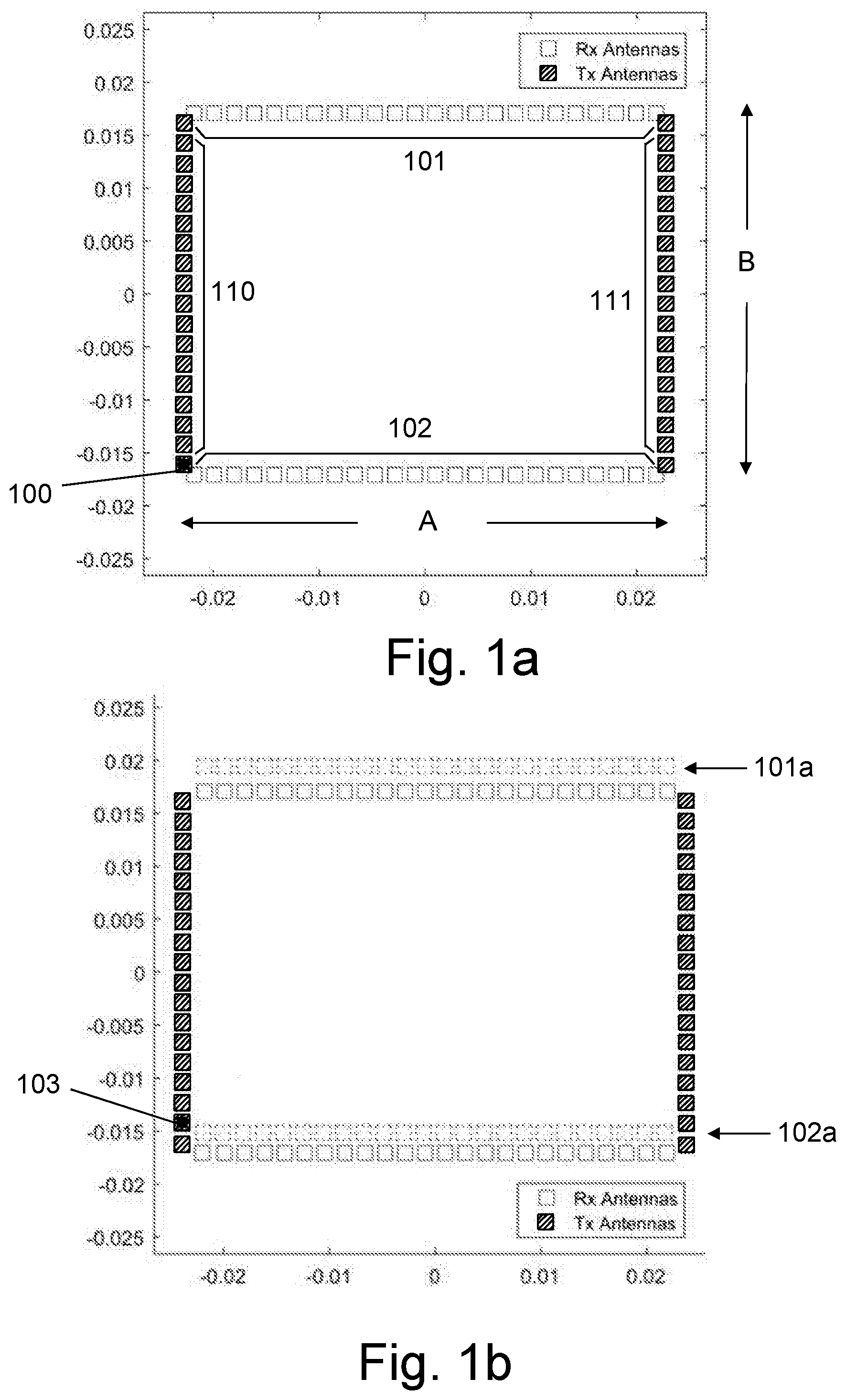
[0037] FIG. 1a illustrates the 1.sup.st layout of a high resolution physical array with reduced number of elements, according to an embodiment of the invention. The first array proposed by the present invention has two parallel rows 101 and 102 (in the azimuth direction), with 72 receive (Rx) elements in each row (which are nominally spaced about 0.5.lamda. from each other) and two parallel columns 110 and 111, with 6 transmit (Tx) elements in each column (which are spaced exactly 72 times the spacing of the Rx elements=36.lamda. from each other). It can be seen that this is a "thin"/"full" rectangular arrangement (consisting of a full transmit array and thinned receive array, or vice versa), in which the rows are "full" in azimuth (i.e., contain a number of elements Rx with about 0.5.lamda. spacing) and the columns are "thin" in azimuth (i.e., contain a number of elements Tx with 72 times the "full" spacing). For elevation, the roles are reversed, with the columns rows being "full" and the columns are "thin".
[0038] In the special case depicted in FIG. 1a, the "thin" size is 2 for both azimuth and elevation, and the equivalent array size is about double the physical size.
[0039] The size of the physical aperture is A.times.B, and is defined by the rectangle dimensions, regardless the total number of elements. In switched mode, the basic concept is to transmit only from one Tx element at a time slot and to receive the reflections in all 48 Rx elements. In this example, transmission begins with transmit element 100 at the lower left location in column 110. The Rx elements in rows 101 and 102 receive the reflected signals. To clarify, the order of the transmitting elements in switched mode can be arbitrary.
[0040] FIG. 1b illustrates how the effective size of the aperture is increased upwardly, without adding more elements. The next transmission is activated from Tx element 103, one location above the lower left location in column 110. This is equivalent to virtually replicating physical rows 101 and 102 one location above, to be virtual rows 101a and 101b. The Rx elements in rows 101a and 102a receive the reflected signals. This process in repeated for all Tx elements in column 110, while each time, an additional replication of physical rows 101 and 102 (which receives the reelected signal) is added, until the areas above row 101 and row 102 are paved with replicated virtual rows. This increases the effective vertical dimension of the aperture rectangle to be 2B (instead of the physical vertical dimension B).
[0041] FIG. 1c illustrates how the effective size of the aperture is increased right without adding more elements. The next transmission is activated from Tx element 104, at the lower right location in column 111. This is equivalent to virtually replicating physical rows 101 and 102 full location to the right, to be virtual rows 101b and 102b. The Rx elements in virtual replicated rows 101b and 102b receive the reflected signals.
[0042] FIG. 1d illustrates how the effective size of the aperture is increased rightwardly, without adding more elements. The next transmission is activated from Tx element 105, one location above the lower right location in column 111. This is equivalent to virtually replicating physical rows 101 and 102 full location to the right and one location above, to be virtual rows 101c and 102c. The Rx elements in rows 101c and 102c receive the reflected signals. This process in repeated for all Tx elements in column 111, while each time, an additional replication of physical rows 101 and 102 (which receives the reelected signal) is added, until the areas above virtual replicated row 101b and row 102b are paved with replicated virtual rows. This increases the effective horizontal dimension of the aperture rectangle to be 2A (instead of the physical horizontal dimension A).
[0043] FIG. 1e illustrates how the effective size of the aperture is increased both upwardly and rightwardly, without adding more elements, as a result of activating all Tx elements, one at a time slot. The resulting equivalent aperture size is 2A.times.2B, twice the aperture determined by the physical elements (which is A.times.B). This doubling of the physical aperture works equally well for simultaneously transmitting antennas using orthogonal waveforms.
[0044] In a 2.sup.nd variation of the above array, each of the 2 column is duplicated (N-1) times by a series of shifts of .lamda./2 each, for example to the right, thus creating two triplets of columns. Total number of elements in all 6 columns is now 6N. For N=3, total number of Tx elements is 36.
[0045] Now the two 72 elements rows are each decimated 3:1 so that each row now has 24 elements with a nominal 3/2.lamda. spacing, and the total number of elements in both rows is 48.
[0046] Transmitting from all 36 elements, whether sequentially all simultaneously, yields an equivalent array of 36.times.48=1728 elements using only 36 TX and 48 RX array elements.
[0047] The two alternatives designs above exemplify how to tradeoff the number of Tx and Rx elements, e.g. from 12 Tx and 144 Rx, to 36 Tx and 49 Rx. This is crucial when adapting a design to available radar transceiver chips to save chip count. The radar front end is based on the ST Microelectronics radar transceiver chip STRADA770, with 4 Rx channels and 3 Tx channels, with an option to connect several of these chips to create larger arrays. In the proposed design 12 of these chips are used, which gives 48 Rx channels and 36 Tx channels, and allows to get a resolution of about 0.9.degree. in azimuth and 2.4.degree. in elevation (@ boresight before windowing), with FOV of 900 in azimuth and 22.5.degree. in elevation, where the array size is about 13.times.10 cm.
[0048] Without derogating the above, it is noted that `antenna` in this submission is occasionally used as a synonym to an array element. Each array element can be a sub-array of antennas in itself. For example, each of the Tx, or Rx, array elements could be a vertical subarray of antennas by itself.
[0049] Signal Processing
[0050] The processing unit is based on Xilinx Zynq-7000 series combined microprocessor FPGA SoC. This unit controls the radar front-end and simultaneously process the IF data. In each radar frame we transmit a 100 .mu.s chirp of up to 1 GHz bandwidth from each of the 36 Tx channels, where some of the chirps are increasing in frequency (up chirp) and some decreasing (down chirp). The processing unit get the sampled IF data via parallel bus using an integrated FIFO buffer. Then a 512 point FFT is computed for each Rx-Tx pair. Then we use another 3D FFT on the result (corresponding to velocity, azimuth and elevation dimensions), but in an hierarchical manner, so only bins where there is a reasonable probability of target presence will be processed in the next steps. This approach yields a sparse output from each FFT step to the next which in the average case significantly reduce the amount of processing. Finally, a list of 4-D voxels (range, velocity, azimuth, elevation) is generated with indication to the probability that a target is preset in this voxel. This probability is computed against the noise distribution (null hypothesis) calculated in the negative frequency spectrum which is always composed just from the noise components and never from real targets.
[0051] While some embodiments of the invention have been described by way of illustration, it will be apparent that the invention can be carried out with many modifications, variations and adaptations, and with the use of numerous equivalents or alternative solutions that are within the scope of persons skilled in the art, without exceeding the scope of the claims.
* * * * *
D00000
D00001
D00002
D00003
XML
uspto.report is an independent third-party trademark research tool that is not affiliated, endorsed, or sponsored by the United States Patent and Trademark Office (USPTO) or any other governmental organization. The information provided by uspto.report is based on publicly available data at the time of writing and is intended for informational purposes only.
While we strive to provide accurate and up-to-date information, we do not guarantee the accuracy, completeness, reliability, or suitability of the information displayed on this site. The use of this site is at your own risk. Any reliance you place on such information is therefore strictly at your own risk.
All official trademark data, including owner information, should be verified by visiting the official USPTO website at www.uspto.gov. This site is not intended to replace professional legal advice and should not be used as a substitute for consulting with a legal professional who is knowledgeable about trademark law.