Runout Detection Device
XUE; Bowen ; et al.
U.S. patent application number 16/404389 was filed with the patent office on 2020-01-02 for runout detection device. This patent application is currently assigned to CITIC Dicastal CO., LTD. The applicant listed for this patent is CITIC Dicastal CO., LTD. Invention is credited to Jiandong GUO, Changcun XIAO, Bowen XUE, Haifeng YUAN.
| Application Number | 20200003541 16/404389 |
| Document ID | / |
| Family ID | 63972568 |
| Filed Date | 2020-01-02 |


| United States Patent Application | 20200003541 |
| Kind Code | A1 |
| XUE; Bowen ; et al. | January 2, 2020 |
RUNOUT DETECTION DEVICE
Abstract
The present application relates to a runout detection device, which includes a base plate, lateral plates, guide sleeves, springs and dial gauges, etc. During the operation, the sliding sleeve and the lateral dial gauge are moved along the sliding groove in the lateral formwork, so that the runout of right end of the work piece may be measured. The bottom plate of the lower end measuring device is placed above the base plate, the ball at the top end of the probe is always in contact with the lower end of the work piece under the action of the upper spring, the probe is pressed down when contacting a projection, and the L-shaped plate is rotated clockwise through the head nail, at this time, the runout of the lower end of the work piece may be known by the reading of the lower dial gauge.
| Inventors: | XUE; Bowen; (Qinhuangdao, CN) ; YUAN; Haifeng; (Qinhuangdao, CN) ; XIAO; Changcun; (Qinhuangdao, CN) ; GUO; Jiandong; (Qinhuangdao, CN) | ||||||||||
| Applicant: |
|
||||||||||
|---|---|---|---|---|---|---|---|---|---|---|---|
| Assignee: | CITIC Dicastal CO., LTD Qinhuangdao CN |
||||||||||
| Family ID: | 63972568 | ||||||||||
| Appl. No.: | 16/404389 | ||||||||||
| Filed: | May 6, 2019 |
| Current U.S. Class: | 1/1 |
| Current CPC Class: | G01B 5/003 20130101; G01B 5/201 20130101; G01B 5/18 20130101; G01B 3/28 20130101 |
| International Class: | G01B 5/18 20060101 G01B005/18; G01B 3/28 20060101 G01B003/28 |
Foreign Application Data
| Date | Code | Application Number |
|---|---|---|
| Jul 2, 2018 | CN | 2018107368807 |
Claims
1. Runout detection device, comprising: four feet, a base plate, a left spring, a left guide sleeve, a left screw, a left guide post, a support column, a right spring, a right guide sleeve, a right screw, a right guide post, a lateral formwork, a sliding sleeve, a lateral dial gauge, a lower dial gauge, a left vertical plate, an upper screw, a fixing block, an upper spring, a probe, a lateral screw, a head nail, lateral vertical plates, a bottom plate, an L-shaped plate and a lower spring, the four feet are fixed at four corners below the base plate; the left guide sleeve is fixed above the base plate; upper part of the left guide post is tapered, and lower part thereof is cylindrical and is matched with inner hole of the left guide sleeve; the left screw is fixed to upper end of the left guide sleeve, and top end of the left screw is matched with a slot in the left guide post; the left spring is installed in the left guide sleeve and provided under the left guide post; the support post is fixed above the base plate, and the right guide sleeve is fixed above the base plate; upper part of the right guide post is tapered, and lower part thereof is cylindrical and is matched with inner hole of the right guide sleeve; the right screw is fixed to upper end of the right guide sleeve, and top end of the right screw is matched with a slot in the right guide post; the right spring installed in the right guide sleeve and provided under the right guide post; the lateral formwork is fixed to right side of the base plate, parallel to the side of the work piece; the lateral formwork is provided with a sliding groove in the measured surface of the side of the measured work piece; the sliding sleeve is matched with the sliding groove in the lateral formwork; the lateral dial gauge is fixed to the sliding sleeve; Lower end measuring device comprises: the lower dial gauge is fixed to left side of the left vertical plate; the fixing block is fixed above the bottom plate and provided on right side of the left vertical plate; two lateral vertical plates are fixed above the bottom plate and respectively provided on front and rear sides of the fixing block; the L-shaped plate is installed between the two lateral vertical plates through pins; the lower spring is installed between the fixing block and the L-shaped plate and provided above the L-shaped plate; the upper screw is installed in upper part of the fixing block, and top end thereof is in contact with top end of left side of the L-shaped plate; top end of the probe is a ball and lower end thereof is a stepped cylinder, and the cylinder of the lower end of the probe is matched with a hole in right side of the fixing block; the upper spring is provided below the probe to ensure that the ball at top end of the probe is configured to be always lifted; the lateral screw is installed in right side of the fixing block, and top end thereof is matched with a slot in the probe; and the head nail is fixed to the L-shaped plate, and a ball at top end of the head nail is always in contact with the lower end of the probe.
Description
CROSS-REFERENCE TO RELATED APPLICATIONS
[0001] This application claims priority to Chinese Patent Application No. 201810736880.7 filed on Jul. 2, 2018, which is hereby incorporated by reference in its entirety.
TECHNICAL FIELD
[0002] The present application relates to a detection device, and more particularly to a runout detection device.
BACKGROUND ART
[0003] The cylinder head of an automobile is generally cast by high-pressure molding, and it is necessary to detect the runout of the depth in order to ensure the depth of the machined seal grooves in the bottom and the side. A runout measurement is usually made by a coordinate measuring machine (CMM), but this measurement is very inefficient thus severely restricting the increase in production efficiency.
SUMMARY OF THE INVENTION
[0004] It is an object of the present application to provide a runout detection device which may measure the runout of a seal groove in the side and the bottom of a high-pressure cast work piece.
[0005] In order to achieve the above object, the technical solution of the present application is: Runout detection device, includes feet, a base plate, a left spring, a left guide sleeve, a left screw, a left guide post, a support column, a right spring, a right guide sleeve, a right screw, a right guide post, a lateral formwork, a sliding sleeve, a lateral dial gauge, a lower dial gauge, a left vertical plate, an upper screw, a fixing block, an upper spring, a probe, a lateral screw, a head nail, lateral vertical plates, a bottom plate, an L-shaped plate and a lower spring. Four feet are fixed at four corners below the base plate. The left guide sleeve is fixed above the base plate. Upper part of the left guide post is tapered, and lower part thereof is cylindrical and is matched with inner hole of the left guide sleeve. The left screw is fixed to upper end of the left guide sleeve, and top end of the left screw is matched with a slot in the left guide post. The left spring is installed in the left guide sleeve and provided under the left guide post. The support post is fixed above the base plate, and the right guide sleeve is fixed above the base plate. Upper part of the right guide post is tapered, and lower part thereof is cylindrical and is matched with inner hole of the right guide sleeve. The right screw is fixed to upper end of the right guide sleeve, and top end of the right screw is matched with a slot in the right guide post. The right spring installed in the right guide sleeve and provided under the right guide post. The lateral formwork is fixed to right side of the base plate, parallel to the side of the work piece. The lateral formwork is provided with a sliding groove in the measured surface of the side of the measured work piece. The sliding sleeve is matched with the sliding groove in the lateral formwork. The lateral dial gauge is fixed to the sliding sleeve.
[0006] Lower end measuring device includes: the lower dial gauge is fixed to left side of the left vertical plate; the fixing block is fixed above the bottom plate and provided on right side of the left vertical plate; two lateral vertical plates are fixed above the bottom plate and respectively provided on front and rear sides of the fixing block; the L-shaped plate is installed between the two lateral vertical plates through pins; the lower spring is installed between the fixing block and the L-shaped plate and provided above the L-shaped plate; the upper screw is installed in upper part of the fixing block, and top end thereof is in contact with top end of left side of the L-shaped plate; top end of the probe is a ball and lower end thereof is a stepped cylinder, and the cylinder of the lower end of the probe is matched with a hole in right side of the fixing block; the upper spring is provided below the probe to ensure that the ball at top end of the probe may be always lifted; the lateral screw is installed in right side of the fixing block, and top end thereof is matched with a slot in the probe; and the head nail is fixed to the L-shaped plate, and a ball at top end of the head nail is always in contact with the lower end of the probe.
[0007] During the operation, two positioning holes in a work piece are respectively matched with the left guide post and the right guide post, and the left guide post and the right guide post are pressed downward, so that lower end of the work piece is simultaneously in contact with upper ends of the left guide sleeve, the right guide sleeve and the support column. Left side of a flange on the sliding sleeve is always in contact with right side of the lateral formwork, the sliding sleeve and the lateral dial gauge are moved along the sliding groove in the lateral formwork, so that the runout of right end of the work piece may be measured. The bottom plate of the lower end measuring device is placed above the base plate, the ball at the top end of the probe is always in contact with the lower end of the work piece under the action of the upper spring, the probe is pressed down when contacting a projection, and the L-shaped plate is rotated clockwise through the head nail, at this time, the runout of the lower end of the work piece may be known by the reading of the lower dial gauge.
[0008] The application may measure the runout of the sealing groove in the side and the bottom of the high-pressure cast work piece in use, and has the characteristics of high measurement precision, simple structure and low production cost.
BRIEF DESCRIPTION OF DRAWINGS
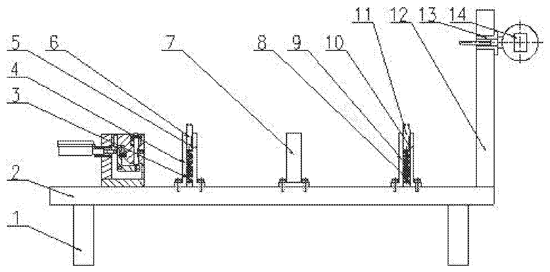
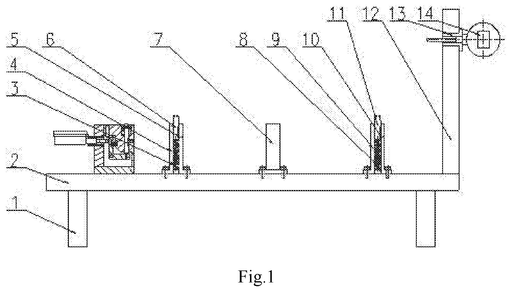
[0009] FIG. 1 is a front view of a runout detection device of the present application.
[0010] FIG. 2 is a right view of the runout detection device of the present application.
[0011] FIG. 3 is a front view of a lower end measuring device of the present application.
[0012] FIG. 4 is a front view of the runout detection device of the present application after the work piece is clamped.
[0013] In which, 1--foot, 2--base plate, 3--left spring, 4--left guide sleeve, 5--left screw, 6--left guide post, 7--support column, 8--right spring, 9--right guide sleeve, 10--right screw, 11--right guide post, 12--lateral formwork, 13--sliding sleeve, 14--lateral dial gauge, 15--lower dial gauge, 16--left vertical plate, 17--upper thread, 18--fixing block, 19--upper spring, 20--probe, 21--lateral screw, 22--head nail, 23--lateral vertical plate, 24--bottom plate, 25--L-shaped plate, 26--lower spring.
DETAILED DESCRIPTION OF THE INVENTION
[0014] The details and operation of a specific device according to the present application will be described below with reference to the accompanying drawings.
[0015] The device includes feet 1, a base plate 2, a left spring 3, a left guide sleeve 4, a left screw 5, a left guide post 6, a support column 7, a right spring 8, a right guide sleeve 9, a right screw 10, a right guide post 11, a lateral formwork 12, a sliding sleeve 13, a lateral dial gauge 14, a lower dial gauge 15, a left vertical plate 16, an upper screw 17, a fixing block 18, an upper spring 19, a probe 20, a lateral screw 21, a head nail 22, lateral vertical plates 23, a bottom plate 24, an L-shaped plate 25 and a lower spring 26. Four feet 1 are fixed at four corners below the base plate 2. The left guide sleeve 4 is fixed above the base plate 2. Upper part of the left guide post 6 is tapered, and lower part thereof is cylindrical and is matched with inner hole of the left guide sleeve 4. The left screw 5 is fixed to upper end of the left guide sleeve 4, and top end of the left screw 5 is matched with a slot in the left guide post 6. The left spring 3 is installed in the left guide sleeve 4 and provided under the left guide post 6. The support post 7 is fixed above the base plate 2, and the right guide sleeve 9 is fixed above the base plate 2. Upper part of the right guide post 11 is tapered, and lower part thereof is cylindrical and is matched with inner hole of the right guide sleeve 9. The right screw 10 is fixed to upper end of the right guide sleeve 9, and top end of the right screw is matched with a slot in the right guide post 11. The right spring 8 installed in the right guide sleeve 9 and provided under the right guide post 11. The lateral formwork 12 is fixed to right side of the base plate 2, parallel to the side of the work piece. The lateral formwork 12 is provided with a sliding groove in the measured surface of the side of the measured work piece. The sliding sleeve 13 is matched with the sliding groove in the lateral formwork 12. The lateral dial gauge 14 is fixed to the sliding sleeve 13.
[0016] Lower end measuring device includes: the lower dial gauge 15is fixed to left side of the left vertical plate 16; the fixing block 18is fixed above the bottom plate 24 and provided on right side of the left vertical plate 16; two lateral vertical plates 23are fixed above the bottom plate 24 and respectively provided on front and rear sides of the fixing block 18; the L-shaped plate 25 is installed between the two lateral vertical plates 23 through pins; the lower spring 26 is installed between the fixing block 18 and the L-shaped plate 25 and provided above the L-shaped plate 25; the upper screw 17 is installed in upper part of the fixing block 18, and top end thereof is in contact with top end of left side of the L-shaped plate 25; top end of the probe 20 is a ball and lower end thereof is a stepped cylinder, and the cylinder of the lower end of the probe 20 is matched with a hole in right side of the fixing block 18; the upper spring 19is provided below the probe 20 to ensure that the ball at top end of the probe 20 may be always lifted; the lateral screw 21is installed in right side of the fixing block 18, and top end thereof is matched with a slot in the probe 20; and the head nail 22is fixed to the L-shaped plate 25, and a ball at top end of the head nail 22 is always in contact with the lower end of the probe 20.
[0017] During the operation, two positioning holes in a work piece are respectively matched with the left guide post 6 and the right guide post 11, and the left guide post 6 and the right guide post 11 are pressed downward, so that lower end of the work piece is simultaneously in contact with upper ends of the left guide sleeve 4, the right guide sleeve 9 and the support column 7. On the sliding sleeve 13, left side of a flange is always in contact with right side of the lateral formwork 12, the sliding sleeve 13 and the lateral dial gauge 14 are moved along the sliding groove in the lateral formwork 12, so that the runout of right end of the work piece may be measured. The bottom plate 24 of the lower end measuring device is placed above the base plate 2, the ball at the top end of the probe 20 is always in contact with the lower end of the work piece under the action of the upper spring 19, the probe 20 is pressed down when contacting a projection, and the L-shaped plate 25 is rotated clockwise through the head nail 22, at this time, the runout of the lower end of the work piece may be known by the reading of the lower dial gauge 15.
[0018] The foregoing descriptions of specific exemplary embodiments of the present invention have been presented for purposes of illustration and description. They are not intended to be exhaustive or to limit the invention to the precise forms disclosed, and obviously many modifications and variations are possible in light of the above teachings. The exemplary embodiments were chosen and described in order to explain certain principles of the invention and their practical application, to thereby enable others skilled in the art to make and utilize various exemplary embodiments of the present invention, as well as various alternatives and modifications thereof. It is intended that the scope of the invention be defined by the claims appended hereto and their equivalents.
* * * * *
D00000
D00001
D00002
D00003
D00004
XML
uspto.report is an independent third-party trademark research tool that is not affiliated, endorsed, or sponsored by the United States Patent and Trademark Office (USPTO) or any other governmental organization. The information provided by uspto.report is based on publicly available data at the time of writing and is intended for informational purposes only.
While we strive to provide accurate and up-to-date information, we do not guarantee the accuracy, completeness, reliability, or suitability of the information displayed on this site. The use of this site is at your own risk. Any reliance you place on such information is therefore strictly at your own risk.
All official trademark data, including owner information, should be verified by visiting the official USPTO website at www.uspto.gov. This site is not intended to replace professional legal advice and should not be used as a substitute for consulting with a legal professional who is knowledgeable about trademark law.