Dehumidifier
Yoon; Chul Min
U.S. patent application number 16/480990 was filed with the patent office on 2020-01-02 for dehumidifier. The applicant listed for this patent is WINIX INC.. Invention is credited to Chul Min Yoon.
| Application Number | 20200003451 16/480990 |
| Document ID | / |
| Family ID | 63370811 |
| Filed Date | 2020-01-02 |


| United States Patent Application | 20200003451 |
| Kind Code | A1 |
| Yoon; Chul Min | January 2, 2020 |
DEHUMIDIFIER
Abstract
A dehumidifier according to an embodiment comprises: a dehumidifier main body provided with a suction port for suctioning air and a discharge port for discharging dehumidified air to the outside; an evaporator disposed in the dehumidifier main body and removing moisture in the air suctioned through the suction port; and a compressor connected to the evaporator inside the dehumidifier main body and compressing a refrigerant for exchanging heat with the air inside the evaporator, wherein dehumidified water can be generated on the surface of the evaporator, and removed therefrom by means of the vibration of the compressor.
| Inventors: | Yoon; Chul Min; (Siheung, KR) | ||||||||||
| Applicant: |
|
||||||||||
|---|---|---|---|---|---|---|---|---|---|---|---|
| Family ID: | 63370811 | ||||||||||
| Appl. No.: | 16/480990 | ||||||||||
| Filed: | March 2, 2017 | ||||||||||
| PCT Filed: | March 2, 2017 | ||||||||||
| PCT NO: | PCT/KR2017/002265 | ||||||||||
| 371 Date: | July 25, 2019 |
| Current U.S. Class: | 1/1 |
| Current CPC Class: | F24F 3/1405 20130101; F24F 3/14 20130101; F24F 13/10 20130101; F24F 2013/202 20130101; F24F 13/22 20130101; F24F 2013/205 20130101; F24F 13/20 20130101; F24F 13/222 20130101 |
| International Class: | F24F 13/10 20060101 F24F013/10; F24F 13/20 20060101 F24F013/20 |
Foreign Application Data
| Date | Code | Application Number |
|---|---|---|
| Feb 28, 2017 | KR | 10-2017-0026500 |
Claims
1. A dehumidifier comprising: a dehumidifier body having an inlet through which air is suctioned and an outlet through which dehumidified air is discharged to an outside; an evaporator disposed in the dehumidifier body to remove moisture in the air suctioned through the inlet; and a compressor connected to the evaporator in the dehumidifier body to compress a refrigerant for exchanging heat with the air in the evaporator, wherein dehumidification water is generated on a surface of the evaporator and the dehumidification water is removed from the surface of the evaporator due to a vibration of the compressor.
2. The dehumidifier of claim 1, further comprising: a housing configured to accommodate the evaporator and the compressor therein, wherein the housing is attached to a bottom surface of the dehumidifier body.
3. The dehumidifier of claim 2, further comprising: a vibration absorbing member disposed in the dehumidifier body to absorb the vibration generated in the compressor, wherein the vibration absorbing member comprises: a damper configured to connect a lower surface of the housing and the bottom surface of the dehumidifier body; a grommet spaced apart from the damper, the lower surface of the housing being located therebetween; and a fixing element configured to fix the compressor in the housing, and the vibration is absorbed by the damper or the grommet.
4. The dehumidifier of claim 2, further comprising: a vibration transfer member configured to transfer the vibration generated in the compressor to the evaporator, wherein the vibration transfer member comprises the housing or a refrigerant line configured to connect the compressor and the evaporator.
5. The dehumidifier of claim 2, wherein a dehumidification water tray is disposed below the evaporator in the housing and the dehumidification water moves from a surface of the evaporator toward the dehumidification water tray.
6. The dehumidifier of claim 2, further comprising: a condenser disposed in the housing to be spaced apart from the evaporator in parallel to an exhaust direction.
7. A dehumidifier comprising: a dehumidifier body having an inlet through which air is suctioned and an outlet through which dehumidified air is discharged to an outside; a housing mounted in the dehumidifier body; an evaporator disposed in an upper part of the housing to remove moisture in air suctioned from the outside; and a compressor disposed in a lower part of the housing to compress a refrigerant for exchanging heat with the air in the evaporator, wherein the evaporator and the compressor are connected to each other such that a vibration generated in the compressor is transferred to the evaporator.
8. The dehumidifier of claim 7, wherein the dehumidifier body comprises: a damper configured to connect a lower surface of the housing and a bottom surface of the dehumidifier body; a grommet spaced apart from the damper, the lower surface of the housing being located therebetween; and a fixing element configured to extend from an inner surface of the housing toward a side surface of the compressor through the grommet, wherein the damper or the grommet is configured to absorb the vibration generated in the compressor.
9. The dehumidifier of claim 7, wherein dehumidification water is generated on a surface of the evaporator and the vibration of the compressor is transferred to the evaporator such that the dehumidification water is removed from the surface of the evaporator.
Description
TECHNICAL FIELD
[0001] One or more example embodiments relate to a dehumidifier and, more particularly, to a dehumidifier that transfers a vibration of a compressor to effectively remove dehumidification water generated on a surface of an evaporator therefrom.
BACKGROUND ART
[0002] In most cases, a dehumidifier may employ a cooling-type dehumidification that removes humidity by condensing moisture contained in air while the air passing through an evaporator based on a refrigeration cycle.
[0003] Such dehumidifier may include a case that forms an appearance, a fan installed in the case to suction external air, a dehumidifying mean that removes moisture by condensing humidity contained in the suctioned air, and a water tank in which water generated in the dehumidifying mean is stored.
[0004] The dehumidifying mean may include a compressor that compresses a gaseous refrigerant at a high temperature and a high pressure, a condenser that condenses the refrigerant gas discharged from the compressor with the high temperature and the high pressure, and an evaporator that evaporates a low-pressure refrigerant having passed through the evaporator and a capillary (inflation tube).
[0005] In such dehumidifier, a refrigerant is circulated by the compressor from the evaporator, through the condenser and the capillary, to the evaporator again. When air is suctioned into a case due to rotation of the fan, the suctioned air may be cooled by the refrigerant to be below the dew point while passing the evaporator and condensed such that moisture contained in the air is formed to be waterdrop, and then removed.
[0006] In this instance, to prevent degradation in heat exchange efficiency due to the humidity generated on the heat exchanger, the humidity needs to be quickly removed.
[0007] For example, Korea Patent Application No. 10-2014-0133285 filed on Oct. 2, 2014 discloses a dehumidifier.
DISCLOSURE OF INVENTION
Technical Goals
[0008] An aspect provides a dehumidifier that effectively removes moisture (or dehumidification water) generated on a surface of a heat exchanger (particularly, the dehumidifier) therefrom using a vibration of a compressor.
[0009] Another aspect provides a dehumidifier that quickly removes moisture (or dehumidification water) generated on a surface of a heat exchanger (particularly, the dehumidifier), thereby improving a heat exchange efficiency of the heat exchanger and improving a dehumidifying performance or dehumidifying efficiency of the dehumidifier.
[0010] Still another aspect provides a dehumidifier that prevents a vibration generated in a compressor from being transferred to a dehumidifier body and allows the vibration to be effectively transferred to the dehumidifier.
Technical Solutions
[0011] According to an aspect, there is provided a dehumidifier including a dehumidifier body having an inlet through which air is suctioned and an outlet through which dehumidified air is discharged to an outside, an evaporator disposed in the dehumidifier body to remove moisture in the air suctioned through the inlet, and a compressor connected to the evaporator in the dehumidifier body to compress a refrigerant for exchanging heat with the air in the evaporator, wherein dehumidification water is generated on a surface of the evaporator and the dehumidification water is removed from the surface of the evaporator due to a vibration of the compressor.
[0012] The dehumidifier may further include a housing configured to accommodate the evaporator and the compressor therein. The housing may be attached to a bottom surface of the dehumidifier body.
[0013] The dehumidifier may further include a vibration absorbing member disposed in the dehumidifier body to absorb the vibration generated in the compressor. The vibration absorbing member may include a damper configured to connect a lower surface of the housing and the bottom surface of the dehumidifier body, a grommet spaced apart from the damper, the lower surface of the housing being located therebetween, and a fixing element configured to fix the compressor in the housing. The vibration may be absorbed by the damper or the grommet.
[0014] The dehumidifier may further include a vibration transfer member configured to transfer the vibration generated in the compressor to the evaporator. The vibration transfer member may include the housing or a refrigerant line configured to connect the compressor and the evaporator.
[0015] A dehumidification water tray may be disposed below the evaporator in the housing. The dehumidification water may move from a surface of the evaporator toward the dehumidification water tray.
[0016] The dehumidifier may further include a condenser disposed in the housing to be spaced apart from the evaporator in parallel to an exhaust direction.
[0017] According to another aspect, there is also provided a dehumidifier including a dehumidifier body having an inlet through which air is suctioned and an outlet through which dehumidified air is discharged to an outside, a housing mounted in the dehumidifier body, an evaporator disposed in an upper part of the housing to remove moisture in air suctioned from the outside, and a compressor disposed in a lower part of the housing to compress a refrigerant for exchanging heat with the air in the evaporator, wherein the evaporator and the compressor are connected to each other such that a vibration generated in the compressor is transferred to the evaporator.
[0018] The dehumidifier body may include a damper configured to connect a lower surface of the housing and a bottom surface of the dehumidifier body, a grommet spaced apart from the damper, the lower surface of the housing being located therebetween, and a fixing element configured to extend from an inner surface of the housing toward a side surface of the compressor through the grommet. The damper or the grommet may be configured to absorb the vibration generated in the compressor.
[0019] Dehumidification water may be generated on a surface of the evaporator. The vibration of the compressor may be transferred to the evaporator such that the dehumidification water is removed from the surface of the evaporator.
Effects
[0020] According to example embodiments, it is possible to effectively remove moisture (or dehumidification water) generated on a surface of a heat exchanger (particularly, a dehumidifier) therefrom using a vibration of a compressor.
[0021] According to example embodiments, it is possible to quickly remove moisture (or dehumidification water) generated on a surface of a heat exchanger (particularly, a dehumidifier), thereby improving a heat exchange efficiency of the heat exchanger and improving a dehumidifying performance or dehumidifying efficiency of the dehumidifier.
[0022] According to example embodiments, it is possible to prevent a vibration generated in a compressor from being transferred to a dehumidifier body and allow the vibration to be effectively transferred to a dehumidifier.
BRIEF DESCRIPTION OF DRAWINGS
[0023] FIG. 1 is a perspective view illustrating a dehumidifier according to an example embodiment.
[0024] FIG. 2 illustrates an internal structure of a dehumidifier according to an example embodiment.
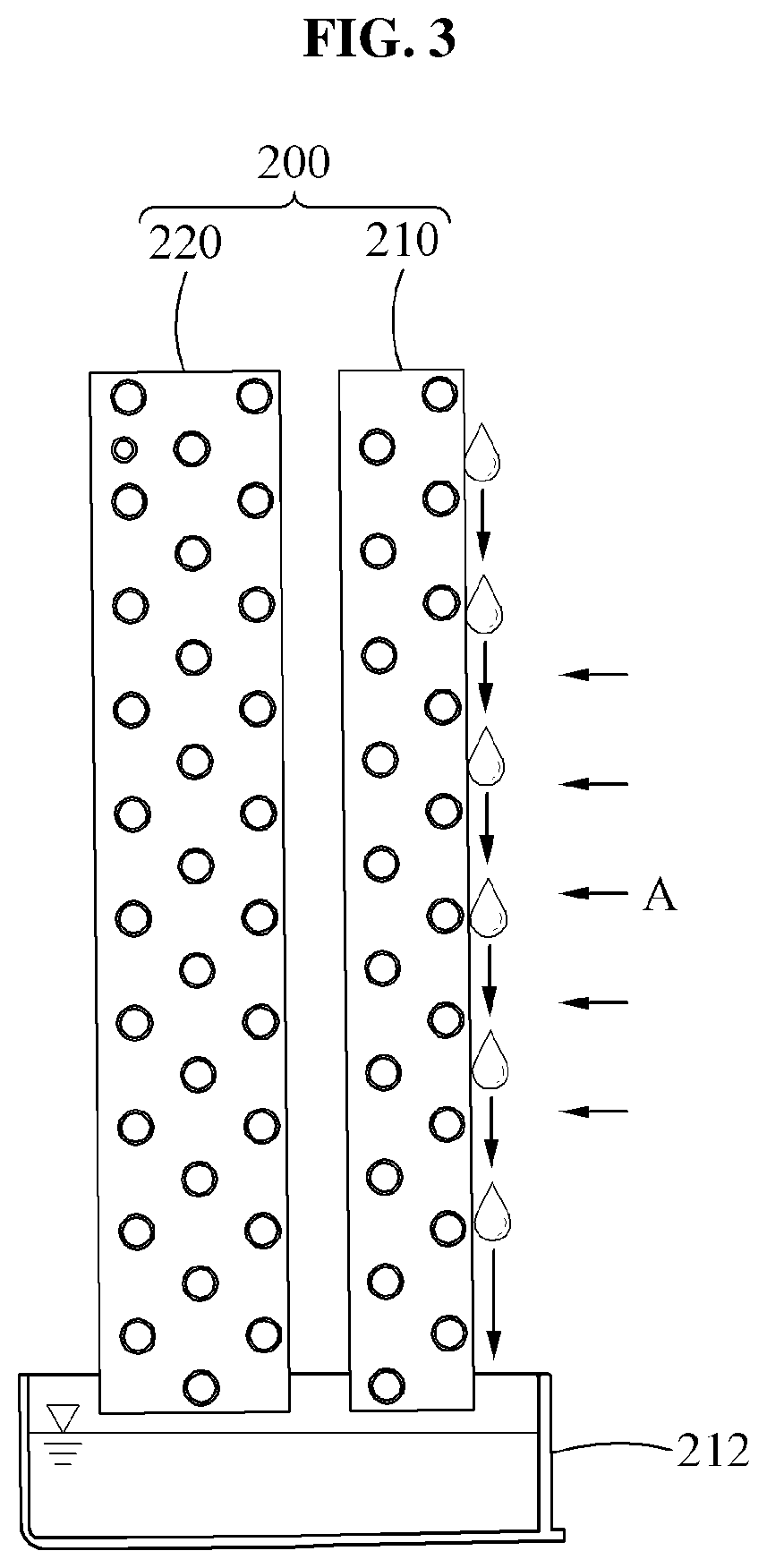
[0025] FIG. 3 illustrates an example of removing dehumidification water from a surface of an evaporator.
BEST MODE FOR CARRYING OUT THE INVENTION
[0026] Hereinafter, example embodiments will be described in detail with reference to the accompanying drawings. It should be understood, however, that there is no intent to limit this disclosure to the particular example embodiments disclosed. On the contrary, example embodiments are to cover all modifications, equivalents, and alternatives falling within the scope of the example embodiments.
[0027] Although terms such as "first," "second," and "third" may be used herein to describe various members, components, regions, layers, or sections, these members, components, regions, layers, or sections are not to be limited by these terms. Throughout the specification, when an element, such as a layer, region, or substrate, is described as being "on," "connected to," or "coupled to" another element, it may be directly "on," "connected to," or "coupled to" the other element, or there may be one or more other elements intervening therebetween.
[0028] Regarding the reference numerals assigned to the elements in the drawings, it should be noted that the same elements will be designated by the same reference numerals, wherever possible, even though they are shown in different drawings. Also, in the description of embodiments, detailed description of well-known related structures or functions will be omitted when it is deemed that such description will cause ambiguous interpretation of the present disclosure.
[0029] FIG. 1 is a perspective view illustrating a dehumidifier according to an example embodiment, FIG. 2 illustrates an internal structure of a dehumidifier according to an example embodiment, and FIG. 3 illustrates an example of removing dehumidification water from a surface of an evaporator.
[0030] Referring to FIGS. 1 and 2, a dehumidifier 10 may include a dehumidifier body 100 and a heat exchanger 200.
[0031] The dehumidifier body 100 may be a device for dehumidifying external humid air to be dry air. The dehumidifier body 100 may have an inlet 102 on one side to suction the external humid air and an outlet 104 on the other side to discharge the dry air. Grills may be disposed at the inlet 102 and the outlet 104.
[0032] Although FIG. 1 illustrates that the inlet 102 is formed in an upper portion of a front surface of the dehumidifier body 100 and the outlet 104 is formed in an upper surface of the dehumidifier body 100, arrangements of the inlet 102 and the outlet 104 are not limited thereto and may be variously changed depending on a design and a condition of the dehumidifier 100.
[0033] A wheel 1110 may be attached to the dehumidifier body 100. The wheel 110 is disposed below the dehumidifier body 100 such that the dehumidifier body 100 is moved with increased convenience. For example, the dehumidifier body 100 may be conveniently moved on a floor. As such, the dehumidifier body 100 may be moved easily with less effort when compared to a case in which the dehumidifier 100 is lifted and moved directly.
[0034] Also, the dehumidifier body 100 may include a display 120 that externally displays an operation state of the dehumidifier body 100 or controls an operation of the dehumidifier body 100.
[0035] The display 120 may be disposed in front of the outlet 104 on the upper surface of the dehumidifier body 100.
[0036] For example, the display 120 may include a display member and a control member. The display member may display the operation state of the dehumidifier body 100. The control member may control the operation of the dehumidifier body 100 or the display 120.
[0037] A heat exchanger 200 may be disposed in the dehumidifier body 100.
[0038] The heat exchanger 200 may include an evaporator 210, a condenser 220, a blower 230, and a compressor 240.
[0039] The evaporator 210 may be a heat exchanger that removes moisture from humid air A suctioned through the inlet 102 and disposed adjacent to the inlet 102 in the dehumidifier body 100. The evaporator 210 may include a low-temperature refrigerant that is heat-exchanged with air passing through the evaporator 210.
[0040] Thus, the humid air A may be cooled to a temperature below the dew point while passing through the evaporator 210. Also, the moisture contained in the humid air A may form a droplet on a surface of the evaporator 210 and fall along the surface of the evaporator 210.
[0041] In this example, a dehumidification water tray 212 may be disposed below the evaporator 210 to collect dehumidification water. As shown in FIG. 3, the dehumidification water generated on the surface of the evaporator 210 may move from the surface of the evaporator 210 toward the dehumidification water tray 212.
[0042] The condenser 220 may be disposed at one side from the evaporator 210 such that the air dehumidified in the evaporator 210 is transferred to the condenser 220.
[0043] The condenser 220 may be disposed between the evaporator 210 and the outlet 104 to be spaced apart from the evaporator 210 in parallel to an exhaust direction.
[0044] The blower 230 may be a device for forcibly blowing air, and may be disposed on an air passage formed between the inlet 102 and the outlet 104. For example, the blower 230 may be disposed between the condenser 220 and a rear surface of the dehumidifier body 100, so that the air passing through the condenser 220s is guided by the blower 230 toward the outlet 104. It is obvious that various kinds of blowing fans may be used as the blower 230 depending on a design and a condition of the dehumidifier 10.
[0045] The compressor 240 may be a device for compressing a refrigerant, and may be disposed on a refrigerant flow path through which the refrigerant flows from the evaporator 210 to the condenser 220. For example, the compressor 240 may receive the refrigerant from the evaporator 210, compress the refrigerant at a high temperature and a high pressure, and transfer the compressed refrigerant to the condenser 220.
[0046] In the dehumidifier 10, the dehumidification water generated on the surface of the evaporator 210 may be removed from the surface of the evaporator 210 due to a vibration of the compressor 240.
[0047] Specifically, the dehumidifier 10 may further include a vibration transfer member 300 that transfers the vibration generated in the compressor 240 to the evaporator 210.
[0048] The vibration transfer member 300 may include a refrigerant line 310 connecting, for example, the evaporator 210 and the compressor 220.
[0049] One end of the refrigerant line 310 may be connected to the compressor 220 and the other end of the refrigerant line 310 may be connected to the evaporator 210, so that the vibration generated in the compressor 220 is transferred to the evaporator 210.
[0050] Through this, the vibration generated in the compressor 240 may be transferred to the evaporator 210 through the refrigerant line 310, so that the dehumidification water generated on the surface of the evaporator 210 moves from the surface of the evaporator 210 toward the dehumidification water tray 212 as illustrated in FIG. 3. As such, while the dehumidifier 10 is in operation, the dehumidification water generated on the surface of the evaporator 210 is naturally removed from the evaporator 210.
[0051] Also, the vibration transfer member 300 may include a housing 320.
[0052] The housing 320 may be disposed in the dehumidifier body 100 to accept the evaporator 210 and the compressor 240 therein.
[0053] Additionally, the housing 320 may further include the condenser 220 at one side from the evaporator 210. Depending on an example, the condenser 220 may be disposed inside the housing 320 or outside the housing 320.
[0054] Specifically, the evaporator 210 and the condenser 220 may be disposed in an upper part of the housing 320, and the compressor 240 may be disposed in a lower part of the housing 320.
[0055] The housing 320 and the compressor 240 may be connected to each other.
[0056] Through this, the vibration generated in the compressor 240 may be transferred to the housing 320 and transferred to the evaporator 210 included in the housing 320, so that the dehumidification water generated on the surface of the evaporator 210 moves from the surface of the evaporator 210 toward the dehumidification water tray 212 as illustrated in FIG. 3. As such, while the dehumidifier 10 is in operation, the dehumidification water generated on the surface of the evaporator 210 is naturally removed from the evaporator 210.
[0057] The aforementioned configuration of the vibration transfer member 300 is not to be taken as being limited thereto, and any configuration capable of effectively transferring the vibration generated in the compressor 220 to the evaporator 210 may be applicable here.
[0058] The dehumidifier 10 may further include a vibration absorbing member 400 that absorbs the vibration generated in the compressor 240.
[0059] The vibration absorbing member 400 may be disposed on a bottom surface in the dehumidifier body 100.
[0060] Specifically, the vibration absorbing member 400 may include a damper 410, a grommet 420, and a fixing element 430.
[0061] The damper 410 may connect a lower surface of the housing 320 and the bottom surface of the dehumidifier body 100. The damper 410 may vertically extend from the bottom surface of the dehumidifier body 100 toward the lower surface of the housing 320, so that the housing 320 and the bottom surface of the dehumidifier body 100 are fixed to be space apart from each other.
[0062] The grommet 420 may be spaced apart from the damper 410 such that the lower surface of the housing 320 is located therebetween. Through this, the grommet 420 may be disposed inside the housing 320 and the damper 410 may be disposed outside the housing 320. Also, the grommet 420 may extend in a longitudinal direction of the damper 410 and disposed on the same axis as the damper 410.
[0063] The grommet 420 may allow the compressor 240 to be spaced apart from the lower surface of the housing 320 and prevent the compressor 240 being directly fixed to the housing 320.
[0064] The fixing element 420 may fix the compressor 240 in the housing 320 and extend from an inner surface of the housing 320 toward a side surface of the compressor 240 through the grommet 420. Any number and arrangement of fixing elements 420 that allow the compressor 240 to be stably fixed in the housing 320 may be applicable here.
[0065] The vibration generated in the compressor 240 may be effectively absorbed by the vibration absorbing member 400, for example, the damper 410 or the grommet 420. Accordingly, the vibration generated in the compressor 240 may be prevented from being transferred to the dehumidifier body 100, and may be transferred to only the evaporator 240.
[0066] The aforementioned configuration of the vibration absorbing member 400 is not to be taken as being limited thereto, and any configuration capable of preventing the vibration generated in the housing 320, specifically, generated in the compressor 240 from being transferred to the dehumidifier body 100 may be applicable here.
[0067] As such, a dehumidifier may effectively remove moisture (or dehumidification water) generated on a surface of a heat exchanger (for example, the dehumidifier) therefrom using a vibration of a compressor and quickly remove the moisture (or dehumidification water) generated on the surface of the heat exchanger (for example, the dehumidifier), thereby improving a heat exchange efficiency and improving a dehumidification performance or dehumidification efficiency of the dehumidifier.
[0068] A number of example embodiments have been described above. Nevertheless, it should be understood that various modifications may be made to these example embodiments. For example, suitable results may be achieved if the described techniques are performed in a different order and/or if components in a described system, architecture, device, or circuit are combined in a different manner and/or replaced or supplemented by other components or their equivalents. Accordingly, other implementations are within the scope of the following claims.
* * * * *
D00000
D00001
D00002
D00003
XML
uspto.report is an independent third-party trademark research tool that is not affiliated, endorsed, or sponsored by the United States Patent and Trademark Office (USPTO) or any other governmental organization. The information provided by uspto.report is based on publicly available data at the time of writing and is intended for informational purposes only.
While we strive to provide accurate and up-to-date information, we do not guarantee the accuracy, completeness, reliability, or suitability of the information displayed on this site. The use of this site is at your own risk. Any reliance you place on such information is therefore strictly at your own risk.
All official trademark data, including owner information, should be verified by visiting the official USPTO website at www.uspto.gov. This site is not intended to replace professional legal advice and should not be used as a substitute for consulting with a legal professional who is knowledgeable about trademark law.