Wheel Drive Assembly for a Hydrostatic Traction Drive and Hydrostatic Traction Drive
Herrmann; Ronny ; et al.
U.S. patent application number 16/457106 was filed with the patent office on 2020-01-02 for wheel drive assembly for a hydrostatic traction drive and hydrostatic traction drive. The applicant listed for this patent is Robert Bosch GmbH. Invention is credited to Ronny Herrmann, Matthias Mueller, Peer Mumcu.
| Application Number | 20200003302 16/457106 |
| Document ID | / |
| Family ID | 68886407 |
| Filed Date | 2020-01-02 |


| United States Patent Application | 20200003302 |
| Kind Code | A1 |
| Herrmann; Ronny ; et al. | January 2, 2020 |
Wheel Drive Assembly for a Hydrostatic Traction Drive and Hydrostatic Traction Drive
Abstract
In a hydraulic motor and a hydrostatic traction drive with such a hydraulic motor, the regulating of the displacement of the hydraulic motor is done via a pilot-operated pressure regulator. The feedforward controller calculates an estimated motor displacement and relays this to the pressure regulator.
| Inventors: | Herrmann; Ronny; (Neu-Ulm, DE) ; Mueller; Matthias; (Langenau, DE) ; Mumcu; Peer; (Ulm, DE) | ||||||||||
| Applicant: |
|
||||||||||
|---|---|---|---|---|---|---|---|---|---|---|---|
| Family ID: | 68886407 | ||||||||||
| Appl. No.: | 16/457106 | ||||||||||
| Filed: | June 28, 2019 |
| Current U.S. Class: | 1/1 |
| Current CPC Class: | F16H 61/425 20130101; F16H 61/431 20130101; F16H 61/421 20130101; F16H 61/0025 20130101; F16H 2039/005 20130101; F16H 39/00 20130101; F16H 61/4017 20130101 |
| International Class: | F16H 61/421 20060101 F16H061/421; F16H 61/431 20060101 F16H061/431; F16H 39/00 20060101 F16H039/00; F16H 61/00 20060101 F16H061/00; F16H 61/4017 20060101 F16H061/4017 |
Foreign Application Data
| Date | Code | Application Number |
|---|---|---|
| Jun 29, 2018 | DE | 10 2018 210 732.7 |
| Jul 12, 2018 | DE | 10 2018 211 586.9 |
Claims
1. A wheel drive assembly for a hydrostatic traction drive comprising: a hydraulic motor comprising an electrical adjusting unit configured to adjust a motor displacement of the hydraulic motor so as to dictate a constant or continuous relation between a motor drive current and the motor displacement; and an electronic control unit comprising: a pressure regulator configured to regulate the motor displacement in dependence on an actual pressure and a nominal pressure; and a feedforward controller associated with the pressure regulator and configured to preset a preset motor displacement.
2. The wheel drive assembly according to claim 1, wherein the pressure regulator is nonlinear.
3. The wheel drive assembly according to claim 1, wherein at least one of the pressure regulator and the feedforward controller have, as an input variable, a rotational speed limit for the hydraulic motor.
4. The wheel drive assembly according to claim 1, wherein the preset motor displacement is a calculated motor displacement calculated based on a model via the feedforward controller in dependence on the nominal pressure and a motor rotational speed.
5. A hydrostatic traction drive comprising: a wheel drive assembly comprising: a hydraulic motor comprising an electrical adjusting unit configured to adjust a motor displacement of the hydraulic motor so as to dictate a constant or continuous relation between a motor drive current and the motor displacement; and an electronic control unit comprising: a pressure regulator configured to regulate the motor displacement in dependence on an actual pressure and a nominal pressure; and a feedforward controller associated with the pressure regulator and configured to preset a preset motor displacement; and an axial piston pump comprising an adjusting unit configured to adjust a pump delivery volume of the axial piston pump.
6. The hydrostatic traction drive according to claim 5, wherein the preset motor displacement is a calculated motor displacement calculated based on a model via the feedforward controller based on the nominal pressure, a motor rotational speed, a pump rotational speed, and one of the pump delivery volume and a pump swivel angle.
7. The hydrostatic traction drive according to claim 6, wherein the pump swivel angle is a calculated pump swivel angle, which is calculated on the basis of a model with the aid of a volume flow balance.
8. The hydrostatic traction drive according to claim 6, wherein the pump swivel angle is a calculated pump swivel angle, which is calculated on the basis of a model in dependence on a leakage under actual pressure, on the motor rotational speed, and on the pump rotational speed and on the motor drive current.
9. The hydrostatic traction drive according to claim 8, wherein the leakage under actual pressure is a calculated leakage under actual pressure, which is calculated on the basis of a model in dependence on the actual pressure.
10. The hydrostatic traction drive according to claim 6, wherein the nominal pressure is determined based on a model in dependence on at least one of: the pump rotational speed, the motor rotational speed, a control element to relay a driver's wish, a FNR, an inching pedal, and a limit load regulator.
11. The hydrostatic traction drive according to claim 6, wherein at least one of the pressure regulator and the feedforward controller has, as an input variable, a rotational speed limit of the axial piston pump.
12. The hydrostatic traction drive according to claim 6, wherein the adjusting unit of the axial piston pump comprises an actuating cylinder having a first actuating pressure chamber in which a first actuating pressure is set via a first pressure reducing valve, the first actuating pressure being dependent on a preselected first current strength at a first magnet of the first pressure reducing valve.
Description
[0001] This application claims priority under 35 U.S.C. .sctn. 119 to application no. DE 10 2018 210 732.7, filed on Jun. 29, 2018 in Germany, and to application no. DE 10 2018 211 586.9, filed Jul. 12, 2018 in Germany, the disclosures of which are incorporated herein by reference in their entirety.
TECHNICAL FIELD
[0002] The disclosure relates to a wheel drive assembly for a hydrostatic traction drive and to a hydrostatic traction drive having such a wheel drive assembly. A wheel drive assembly is intended to mean a hydraulic motor and an electronic control unit which controls or regulates the hydraulic motor.
BACKGROUND
[0003] Hydrostatic traction drives for mobile working machines are known, in which a hydraulic pump and one or more hydraulic motors are interconnected in a closed hydraulic circuit. The hydraulic pump is driven by an internal combustion engine--e.g. a diesel engine--and the hydraulic motors ultimately drive the mobile working machine--for example via a respective wheel.
[0004] The hydraulic pump of such traction drives is often adjustable in its delivery volume. In this way, for example, the volume flow delivered by the hydraulic pump can be changed in the closed circuit at constant rotational speed of the internal combustion engine and in this way an output rotational speed of the hydraulic motors or of the wheels can be adjusted--i.e. a travel speed of the mobile working machine.
[0005] Furthermore, it is known that the hydraulic motor or motors can also be adjusted in their displacement. In this way, for example, it is possible launching of the particular mobile working machine to increase the delivery volume of the hydraulic pump at first starting from zero up to the maximum value, in order then to reduce the displacement of the hydraulic motors starting from the maximum for faster travel. With this reduction, the output rotational speed is increased at constant volume flow.
[0006] The disclosure relates to the adjusting or regulating of the at least one hydraulic motor. Hydraulically pressure-regulated hydraulic motors are known in this regard. These are relatively cost-intensive and do not allow any variable power setting or any different travel modes.
[0007] Furthermore, rotational speed-controlled adjustments are known. The rotational speed in question may herein be that of the internal combustion engine or that of the hydraulic pump or that of the hydraulic motor. The drawback in both cases is that no physical power setting is possible. Hence, no optimal loading of the internal combustion engine and no optimal power distribution between the traction drive and an operating hydraulics of the mobile working machine, likewise driven by the internal combustion engine, is possible.
[0008] Accordingly, the problem which the disclosure proposes to solve is to create a wheel drive assembly having a hydraulic motor for a traction drive and to create a traction drive having such a wheel drive assembly with which the power of the traction drive can be regulated, e.g., on the basis of power demands.
SUMMARY
[0009] This problem is solved by a wheel drive assembly having the features described herein and by a traction drive having the features described herein.
[0010] The disclosed wheel drive assembly comprises at least one hydraulic motor, which is suitable or designed to be a secondary machine for a hydrostatic traction drive. The traction drive is preferably designed for a mobile working machine. The hydraulic motor comprises an electrical adjusting unit for adjusting the motor displacement, by which a constant or continuous relation or a constant or continuous characteristic curve between a motor drive current and the motor displacement is dictated. According to the disclosure, an electronic control unit is provided, having a pressure regulator, which regulates the motor displacement in dependence on an actual pressure and a nominal pressure. Furthermore, the electronic control unit has a feedforward controller, by which an estimated or calculated motor displacement is relayed to the pressure regulator. The mentioned pressures are working pressures at an input of the hydraulic motor. Hence, a regulation of power of the traction drive is possible. Furthermore, various travel modes having differently attuned power characteristic are possible.
[0011] The relation between the motor drive current and the motor displacement is preferably proportional and the characteristic curve is preferably linear.
[0012] The pressure regulator is preferably nonlinear.
[0013] For reasons of operating safety, it is preferable for the pressure regulator and/or the feedforward controller to have as input variable a rotational speed limit for the hydraulic motor. In this way, the adjusting range of the feedforward controller and/or the pressure regulator is limited. This rotational speed limit can be derived from a velocity limit of the particular mobile working machine.
[0014] In one especially preferred refinement of the wheel drive assembly according to the disclosure, the preset motor displacement is determined on the basis of a model by the feedforward controller at least in dependence on the nominal pressure and a motor rotational speed. In this way, an equalization of system tolerances is possible via the pressure regulator, which are not considered by the model-based feedforward controller. These system tolerances are, e.g., inaccuracies in the adjusting unit or in the adjustment characteristic or leakage tolerances.
[0015] The disclosed hydrostatic traction drive comprises an above-described wheel drive assembly having at least one hydraulic motor, being fluidically connected via a preferably closed circuit to an axial piston pump, comprising an adjusting unit for adjusting its pump delivery volume. The traction drive solves the same problem as the wheel drive assembly according to the disclosure and has the same benefits.
[0016] The feedforward controller can then determine the calculated motor displacement also in dependence on a pump rotational speed and a pump delivery volume or an interrelated pump swivel angle. An internal combustion engine coupled to the axial piston pump of the traction drive according to the disclosure can work under a defined and optimal load.
[0017] The pump swivel angle is preferably calculated on the basis of a model with the aid of the following volume flow balance: "delivery volume flow of the hydraulic pump-leakage at actual pressure=displacement flow of the hydraulic motor".
[0018] In one preferred embodiment, the pump swivel angle is calculated on the basis of a model in dependence on a leakage under actual pressure and on the motor rotational speed and on the pump rotational speed and on the motor drive current.
[0019] In one preferred embodiment, a pressure sensor is provided on the working line of the closed circuit carrying the high pressure. The so-called leakage under actual pressure can then be calculated on the basis of a model in dependence on the measured actual pressure.
[0020] Preferably, the nominal pressure is calculated on the basis of a model in dependence on the pump rotational speed and/or a FNR and/or an inching pedal and/or a limit load regulator. A control element to relay a driver's wish and a motor rotational speed may also be taken into account. This makes possible a model-based control of the demanded nominal pressures of the hydraulic motor and in the working line of the traction drive according to the disclosure carrying high pressure. Instead of the pump rotational speed, an equal or proportional rotational speed of the internal combustion engine may also be considered. In this way, the power of the traction drive can be regulated on the basis of a power demand from the driver. The control element can be an accelerator pedal.
[0021] For reasons of operating safety, it is preferable for the pressure regulator and/or the feedforward controller to have as input variable a rotational speed limit of the axial piston pump. In this way, the adjusting range of the feedforward controller and/or the pressure regulator is limited. This rotational speed limit of the axial piston pump can be derived from a rotational speed limit of the driving internal combustion engine.
[0022] The axial piston pump is preferably of swash-plate design.
[0023] The adjusting unit of the axial piston pump preferably comprises an actuating cylinder having a first actuating pressure chamber, in which a first actuating pressure can be set via a first pressure reducing valve. The first actuating pressure is dependent on a preselected first current strength at a first magnet of the first pressure reducing valve. In this way, a so-called ET-adjusting unit for the axial piston pump is formed. Preferably, the first actuating pressure is proportional to the first current strength.
[0024] In one preferred refinements, in the normal pump operation of the axial piston pump, the actual rotational speed and the first actuating pressure act in the direction of an increase in the pump delivery volume or in the pump swivel angle, while the pressure acts in the direction of a decrease in the pump delivery volume or in the pump swivel angle.
[0025] In one especially preferred refinement, the actuating cylinder comprises a second actuating pressure chamber, which acts in opposition to the first actuating pressure chamber, and in which a second actuating pressure can be set via a second pressure reducing valve. This occurs independently for the two actuating pressure chambers. The second actuating pressure is dependent on a preselected second current strength at a second magnet of the second pressure reducing valve. Preferably, the second actuating pressure is proportional to the second current strength. Hence, the second actuating pressure acts in the direction of the decrease in the stroke volume. In this case, the difference between the first actuating pressure and the second actuating pressure can be called the effective actuating pressure difference. Hence, the axial piston pump is also controllable when it changes to a motor mode, which may occur due to a towing operation of the traction drive according to the disclosure.
BRIEF DESCRIPTION OF THE DRAWINGS
[0026] An exemplary embodiment of the traction drive according to the disclosure is represented in the figures, in which:
[0027] FIG. 1 shows a circuit diagram of the traction drive according to the disclosure in accordance with the exemplary embodiment,
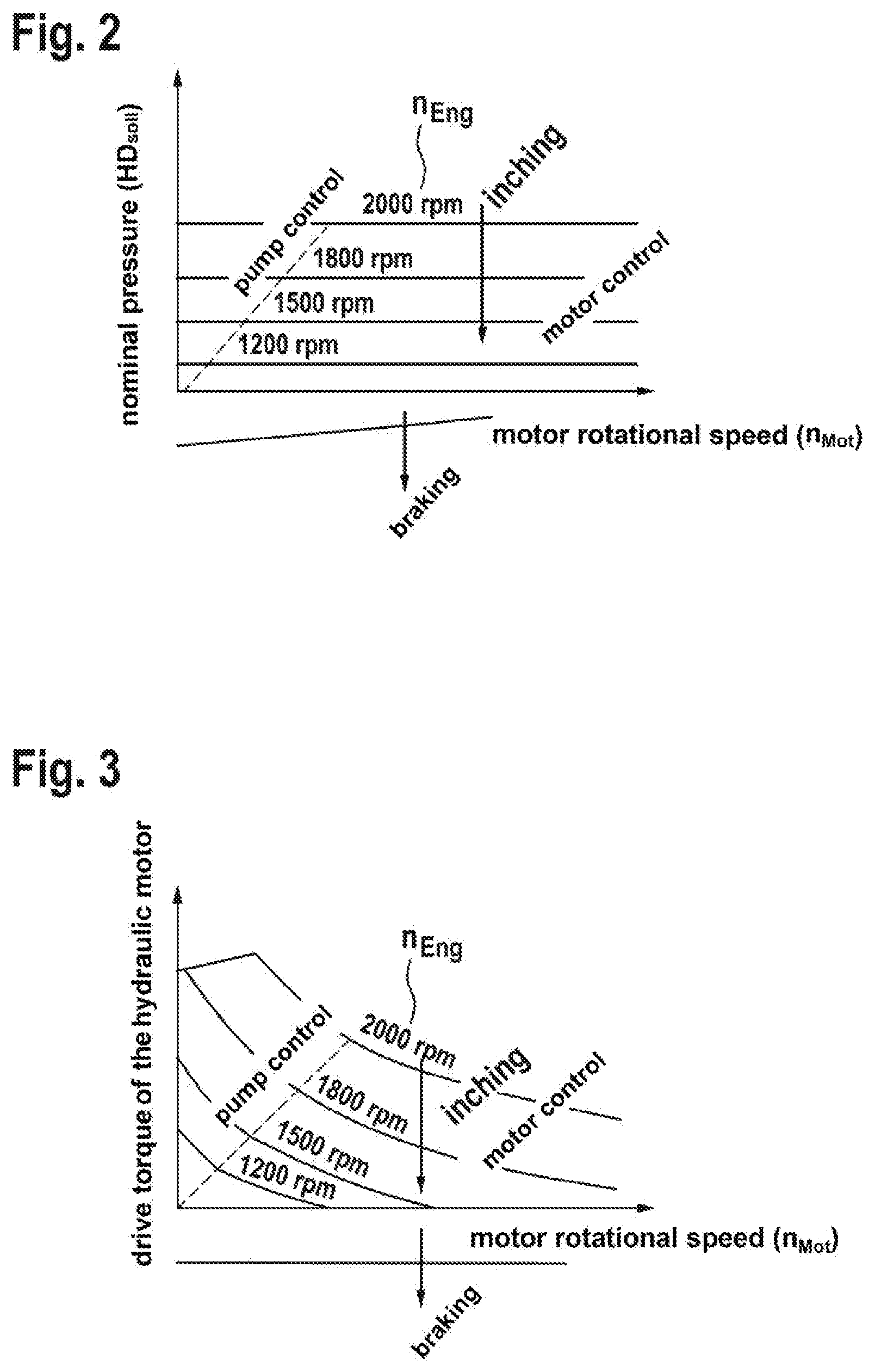
[0028] FIG. 2 shows a diagram for the exemplary embodiment of FIG. 1,
[0029] FIG. 3 shows a further diagram for the exemplary embodiment of FIG. 1,
[0030] FIG. 4 shows a diagram with logic blocks and signal flows of the exemplary embodiment of FIGS. 1, and
[0031] FIG. 5 shows a diagram with multiple parameters plotted against time during launching of the traction drive according to the exemplary embodiment of FIG. 1.
DETAILED DESCRIPTION
[0032] FIG. 1 shows a circuit diagram of the exemplary embodiment of the traction drive according to the disclosure. Only the components relevant to the disclosure are described. The traction drive has an axial piston pump 1, on whose housing two working ports A, B are formed. Via the working ports A, B and via working lines of a closed circuit, a hydraulic motor 3 is fluidically connected to the axial piston pump 1. A wheel (not shown) is coupled in a rotationally fixed manner to an output shaft of the hydraulic motor 3. In this way, a traction drive is formed for a mobile working machine (not shown in more detail).
[0033] The axial piston pump 1 is designed with a swash plate 2, whose pump swivel angle .alpha..sub.Pmp can be set via an adjusting unit 4a. For this, a dual-action actuating cylinder 6 is used, having a first actuating pressure chamber 8.sub.1 and, acting in opposition to this, a second actuating pressure chamber 8.sub.2.
[0034] A first control pressure p.sub.st1 acts in the first actuating pressure chamber 8.sub.1 in the direction of an increase in the swivel angle .alpha..sub.Pmp and thus in the direction of an increase in the pump delivery volume Vg.sub.Pmp. Acting in opposition to this is a second actuating pressure p.sub.st2 in the second actuating pressure chamber 8.sub.2 in the direction of a decrease in the swivel angle .alpha..sub.Pmp and thus in the direction of a decrease in the pump delivery volume Vg.sub.Pmp. In this way, an actuating pressure difference can be defined .DELTA.p.sub.st=p.sub.st1-p.sub.st2, which by definition always acts in the direction of an increase in the pump swivel angle .alpha..sub.Pmp or in the pump delivery volume Vg.sub.Pmp.
[0035] A drive shaft 10 of the axial piston pump 1 drives its power unit 12 and furthermore also a feed pump 14. The drive shaft 10 is driven by a diesel engine (not shown), whose crankshaft rotates with a rotational speed n.sub.Eng. Therefore, the drive shaft 10 rotates with the same or with a proportionally altered pump rotational speed n.sub.Pmp.
[0036] The pump rotational speed n.sub.Pmp acts together with the actuating pressure difference .DELTA.p.sub.st in the direction of an increase in the pump swivel angle .alpha..sub.Pmp. More precisely, an increase in the pump rotational speed n.sub.Pmp acts in this manner.
[0037] When the axial piston pump 1 shown is supplying the hydraulic motor 3 by its working ports A, B, let it be assumed that working port B is the high-pressure port during forward travel of the mobile working machine. Accordingly, the working line connected to the working port B is denoted as high pressure HD, while the other working line is denoted as low pressure ND. The high pressure HD acts in the direction of a decrease in the pump swivel angle .alpha..sub.Pmp. These mentioned effects of the actuating pressure difference .DELTA.p.sub.st, the pump rotational speed n.sub.Pmp and the high pressure HD are measured. Their aforementioned effects on the pump swivel angle .alpha..sub.Pmp are saved in an electronic control unit 16 of the wheel drive assembly according to the disclosure as formulas and/or as characteristic maps or characteristic curves. In this way, operating points of the axial piston machine 1 can be actuated without therefore requiring feedback in the sense of a feedback control circuit.
[0038] The two actuating pressures p.sub.st1, p.sub.st2 are controlled by two pressure reducing valves 18.sub.1, 18.sub.2. These have a respective electromagnet a, b, which are connected via a respective electrical line 20.sub.1, 20.sub.2 to the electronic control unit 16. The two pressure reducing valves 18.sub.1, 18.sub.2 are designed such that the respective actuating pressure p.sub.st1, p.sub.st2 is proportional to the respective current strength i.sub.Pmp Fwd, i.sub.Pmp Rvs.
[0039] The two pressure reducing valves 18.sub.1, 18.sub.2 are supplied at their inlet side from the feed pump 14 via a feed pressure line 22.
[0040] Via an electrical line 25, a control element 26 is connected to the control unit 16 in order to relay the driver's wish, the control element 26 being preferably designed as an accelerator pedal.
[0041] As a secondary machine, the aforementioned hydraulic motor 3 is connected to the two working lines HD, ND of the connected circuit. A motor displacement Vg.sub.Mot is adjustable via an electrical adjusting unit 4b. This is connected via an electrical line 24 to the control unit 16 and is controlled and regulated in the manner of the disclosure described below.
[0042] FIGS. 2 and 3 respectively show a schematic diagram in regard to the control of the traction drive as per FIG. 1. In both diagrams, the motor rotational speed n.sub.Mot and, as examples, several rotational speeds n.sub.Eng of the internal combustion engine are plotted along the X-axis. In FIG. 2, the nominal pressure HD.sub.soll is plotted on the Y-axis. It can be seen herein that the nominal pressure HD.sub.soll is increased by increasing rotational speed n.sub.Eng of the internal combustion engine. In FIG. 3, the output torque of the hydraulic motor is plotted on the Y-axis.
[0043] In both diagrams it is shown schematically that, during a starting and an increase in the velocity of the mobile working machine, corresponding to the motor rotational speed n.sub.Mot, at first a region of a pump controller and then a region of a motor controller is provided. More precisely, at first the adjusting unit 4a is used to increase the pump swivel angle .alpha..sub.Pmp and then the adjusting unit 4b is used to decrease the motor displacement Vg.sub.Mot. If the hydraulic motor 3 is also an axial piston machine, this occurs through reducing the swivel angle of the hydraulic motor 3.
[0044] FIG. 2 shows in an exemplary manner the nominal pressure behavior in dependence on the current rotational speed n.sub.Eng of the internal combustion engine and the influence of an inching pedal. As per FIG. 2, by presetting the nominal pressure characteristic it is possible to define the power of the traction drive. As per FIG. 3, it is possible to define the characteristic of the output torque of the hydraulic motor. The preconditions for this are that the pump swivel angle .alpha..sub.Pmp and the rotational speed n.sub.Eng of the internal combustion engine are constant, as shown by FIG. 2.
[0045] FIG. 4 shows logic blocks and signal flows of the control and regulation of the hydraulic motor 3 according to the disclosure. In logic block 31 there is a calculation of the nominal pressure HD.sub.soll in dependence on the pump rotational speed n.sub.Pmp or the rotational speed n.sub.Eng of the internal combustion engine and in dependence on the motor rotational speed n.sub.Mot and in dependence on the accelerator pedal 26 and in dependence on a FNR and in dependence on the inching pedal and in dependence on a limit load regulator.
[0046] First of all, the nominal pressure HD.sub.soll is preset as a function of the rotational speed n.sub.Eng of the internal combustion engine. The precise dependency on the rotational speed n.sub.Eng is parametrized with a characteristic curve when placing the traction drive of the disclosure in operation, such that the power of the internal combustion engine is utilized meaningfully in operation. The technical details of the internal combustion engine and the kind of usage of the mobile working machine play a role here.
[0047] Furthermore, the inching pedal has an influence on the nominal pressure HD.sub.soll. Depending on the position of the inching pedal, an "inch factor" between 0% and 100% is determined with a characteristic curve, which acts in multiplicative manner on the nominal pressure HD.sub.soll and can therefore reduce it if the driver desires. In addition, there is a "limit load regulator factor" between 0% and 100%, which reduces the nominal pressure HD.sub.soll when the internal combustion engine is overloaded.
[0048] The driving direction lever acts as follows on the nominal pressure HD.sub.soll: when the desired driving direction is set at "neutral", then the nominal pressure HD.sub.soll is set at 0 bar, because the driver then wishes a standstill.
[0049] The nominal pressure HD.sub.soll may furthermore also be dependent on the motor rotational speed n.sub.Mot, and on the position of the control element 26, which is preferably an accelerator pedal.
[0050] This nominal pressure HD.sub.soll serves as an input variable for a logic block 33, in which a model-based determination of the leakage at nominal pressure HD.sub.soll occurs, and for a feedforward controller 35, in which a model-based determination of the motor displacement Vg.sub.Mot occurs, and for a nonlinear pressure regulator 36, which ultimately outputs the motor displacement Vg.sub.Mot to be set.
[0051] Further input variables for the feedforward controller 35 are the calculated leakage at nominal pressure HD.sub.soll of the logic block 33 and the pump rotational speed n.sub.Pmp and the motor rotational speed n.sub.Mot, which are detected by respective rotational speed sensors (not shown). From these values, the feedforward controller 35 calculates a motor displacement Vg.sub.Mot. Use is made herein of the fact that the leakage is a linear function of the pressure.
[0052] The model-based regulator 36 is based on the following volume flow balance:
delivery volume flow Q.sub.Pmp of the hydraulic pump=displacement flow Vg.sub.Mot of the hydraulic motor+leakage at nominal pressure HD.sub.soll
[0053] This equation is solved for the displacement flow Vg.sub.Mot, which is then a function of [0054] the pump rotational speed n.sub.Pmp (measured by sensor) [0055] the motor rotational speed n.sub.Mot (measured by sensor) [0056] the pump swivel angle .alpha..sub.Pmp (estimated with model) [0057] the leakage at nominal pressure HD.sub.soll (estimated with model).
[0058] The motor displacement flow Vg.sub.Mot is then computed with these values, wherein the pump rotational speed n.sub.Pmp and the pump swivel angle .alpha..sub.Pmp are smoothed out with signal filters in order to suppress oscillations of the system.
[0059] The motor displacement Vg.sub.Mot calculated by the feedforward controller 35 serves as an approximate value or starting value for the nonlinear pressure regulator 36. The pressure regulator 36 also has as a further input variable the measured actual pressure HD.sub.ist.
[0060] The actual pressure HD.sub.ist also serves as an input variable for a logic block 32 in which a model-based determination of the leakage at actual pressure HD.sub.ist is done. This value and furthermore the pump rotational speed n.sub.Pmp and the motor rotational speed n.sub.Mot and the motor drive current i.sub.Pmp Fwd or i.sub.Pmp Rvs serve as input variables for a logic block 34. In this block, a model-based determination of the pump swivel angle .alpha..sub.Pmp is done, which serves as a further input variable for the feedforward controller 35.
[0061] Finally, an overspeeding protection means 37a and a velocity limiting means 37b are optionally also provided, whose limit values are taken into account by the feedforward controller 35 and by the pressure regulator 36.
[0062] FIG. 5 shows various values and parameters of the traction drive according to the disclosure as per the preceding figures. More precisely, the behavior of the pressure regulator 36 is shown during a slow acceleration process of the traction drive or the mobile working machine. The driver sets a power request via the control element, which is preferably the accelerator pedal, which request is converted into a nominal pressure HD.sub.soll (dot and dash line). The model-based regulator 35 adapts the motor displacement Vg.sub.Mot so that the actual pressure HD.sub.ist is adjusted.
[0063] A hydraulic motor and a hydrostatic traction drive therewith are disclosed, wherein the regulating of the displacement of the hydraulic motor is done via a pilot-operated pressure regulator. The feedforward controller calculates an estimated motor displacement and relays this to the pressure regulator.
* * * * *
D00000
D00001
D00002
D00003
D00004
XML
uspto.report is an independent third-party trademark research tool that is not affiliated, endorsed, or sponsored by the United States Patent and Trademark Office (USPTO) or any other governmental organization. The information provided by uspto.report is based on publicly available data at the time of writing and is intended for informational purposes only.
While we strive to provide accurate and up-to-date information, we do not guarantee the accuracy, completeness, reliability, or suitability of the information displayed on this site. The use of this site is at your own risk. Any reliance you place on such information is therefore strictly at your own risk.
All official trademark data, including owner information, should be verified by visiting the official USPTO website at www.uspto.gov. This site is not intended to replace professional legal advice and should not be used as a substitute for consulting with a legal professional who is knowledgeable about trademark law.