Water Soluble Sackets of Water Insoluble SiOC Ceramic Pigments
Bening, JR.; P. Scott ; et al.
U.S. patent application number 16/395149 was filed with the patent office on 2020-01-02 for water soluble sackets of water insoluble sioc ceramic pigments. This patent application is currently assigned to Melior Innovations, Inc.. The applicant listed for this patent is Melior Innovations, Inc., MonoSol, LLC.. Invention is credited to David Bening, P. Scott Bening, JR., P Scott Bening.
| Application Number | 20200002226 16/395149 |
| Document ID | / |
| Family ID | 68295700 |
| Filed Date | 2020-01-02 |


View All Diagrams
| United States Patent Application | 20200002226 |
| Kind Code | A1 |
| Bening, JR.; P. Scott ; et al. | January 2, 2020 |
Water Soluble Sackets of Water Insoluble SiOC Ceramic Pigments
Abstract
Cement, concrete, stucco, and plaster that are have black ceramic polymer derived pigment included as an encapsulated water soluble sacket added to the powered or wet materials. A ceramic black SiOC additive encapsulated in a water soluble sacket and having a particle size of about 0.1 .mu.m to 3 .mu.m.
| Inventors: | Bening, JR.; P. Scott; (St John, IN) ; Bening; P Scott; (St John, IN) ; Bening; David; (Columbus, OH) | ||||||||||
| Applicant: |
|
||||||||||
|---|---|---|---|---|---|---|---|---|---|---|---|
| Assignee: | Melior Innovations, Inc. Houston TX MonoSol, LLC. Merrillville IN |
||||||||||
| Family ID: | 68295700 | ||||||||||
| Appl. No.: | 16/395149 | ||||||||||
| Filed: | April 25, 2019 |
Related U.S. Patent Documents
| Application Number | Filing Date | Patent Number | ||
|---|---|---|---|---|
| 62663087 | Apr 26, 2018 | |||
| Current U.S. Class: | 1/1 |
| Current CPC Class: | C04B 2103/54 20130101; C04B 2111/82 20130101; C04B 7/36 20130101; C04B 35/6267 20130101; C04B 28/14 20130101; C04B 14/324 20130101; C04B 28/02 20130101; C04B 28/02 20130101; C04B 40/0608 20130101; C04B 40/0641 20130101; C04B 2103/54 20130101; C04B 28/02 20130101; C04B 14/32 20130101; C04B 40/0608 20130101; C04B 40/0641 20130101; C04B 28/14 20130101; C04B 14/32 20130101; C04B 40/0608 20130101; C04B 40/0641 20130101; C04B 28/14 20130101; C04B 40/0608 20130101; C04B 40/0641 20130101; C04B 2103/54 20130101 |
| International Class: | C04B 14/32 20060101 C04B014/32; C04B 35/626 20060101 C04B035/626 |
Claims
1. A black cement mixture comprising a dry powdered cement and a black water insoluble SiOC ceramic pigment, wherein the pigment is encapsulated in a water soluble sacket.
2. The cement of claim 1, comprising about 6% to about 15% ceramic pigment.
3. The cement of claim 2, comprising at least about 8% ceramic pigment.
4. The cement of claim 2, comprising at least about 10% ceramic pigment.
5. A black concrete comprising a dry powdered cement, aggregate and a black water insoluble SiOC pigment, wherein the pigment is encapsulated in a water soluble sacket.
6. The concrete of claim 5, comprising about 6% to about 15% ceramic pigment to cement.
7. The concrete of claim 6, comprising at least about 8% ceramic pigment to cement.
8. The concrete of claim 6, comprising at least about 10% ceramic pigment to cement.
9. A method for making a black cement, concrete, stucco or plaster structure, adding a water soluble sacket comprising a pyrolized polymer derived ceramic black pigment polymer, wherein the pigment is water insoluble, to a cement, concrete, stucco or plaster material, mixing the combined pigment and material to provide a uniform distribution of the pigment within the material, forming the material into a shape, hardening the material into a black cement, concrete, stucco or plaster structure, whereby the hardened structure has a uniform black color throughout the entirety of a structure.
10. The method of claim 9, wherein the pigment comprises at least about 2% of the structure.
11. The method of claim 9, wherein the pigment comprises at least about 5% of the structure.
12. The method of claim 9, wherein the pigment comprises at least about 8% of the structure.
13. The method of claim 9, wherein the pigment comprises at least about 10% of the structure.
14. The method of claim 9, wherein the pigment comprises at least about 12% of the structure.
15. The method of claim 9, wherein the pigment comprises about 3% to about 8% of the structure.
16. The method of claim 9, wherein the pigment is added to a dry material.
17. The method of claim 9, wherein the pigment is added to a wet material.
18. The method of claim 9, wherein the pigment is added to a liquid material.
19. The method of claim 9, wherein the pigment has a particle size D.sub.50 of less than about 4 .mu.m.
20. The method of claim 9, wherein the pigment has a particle size D.sub.50 of from about 3 .mu.m to about 0.1 .mu.m.
21. The method of claim 9, wherein the pigment has a particle size D.sub.50 of from about 2 .mu.m to about 0.5 .mu.m.
22. The method of claim 9, wherein the structure defines a blackness selected from the group consisting of: PMS 433, Black 3, Black 3, Black 4, Black 5, Black 6, Black 7, Black 2 2.times., Black 3 2.times., Black 4 2.times., Black 5 2.times., Black 6 2.times., and Black 7 2.times..
23. The method of claim 9, wherein the structure defines a uniform blackness throughout the structure, selected from the group consisting of: PMS 433, Black 3, Black 3, Black 4, Black 5, Black 6, Black 7, Black 2 2.times., Black 3 2.times., Black 4 2.times., Black 5 2.times., Black 6 2.times., and Black 7 2.times..
24. The method of claim 9, wherein the structure defines a blackness selected from the group consisting of: Tri-stimulus Colorimeter of X from about 0.05 to about 3.0, Y from about 0.05 to about 3.0, and Z from about 0.05 to about 3.0; a CIE L a b of L of less than about 40; a CIE L a b of L of less about 20; a CIE L a b of L of less than 50, b of less than 1.0 and a of less than 2; and a jetness value of at least about 200 M.sub.y.
25. The method of claim 9, wherein the structure defines a uniform blackness throughout the structure, selected from the group consisting of: Tri-stimulus Colorimeter of X from about 0.05 to about 3.0, Y from about 0.05 to about 3.0, and Z from about 0.05 to about 3.0; a CIE L a b of L of less than about 40; a CIE L a b of L of less about 20; a CIE L a b of L of less than 50, b of less than 1.0 and a of less than 2; and a jetness value of at least about 200 M.sub.y.
26. A water soluble sacket of a water insoluble hydrophilic polymer derived ceramic pigment.
27. The sacket of claim 26, wherein, the water insoluble hydrophilic polymer derived ceramic pigment comprises silicon, carbon and oxygen; and comprises about 40 weight % to about 50 weight % silicon, and wherein about 25 weight % to about 40 weight % of the carbon is silicon-bound-carbon.
28. The sacket of claim 26, wherein, the water insoluble hydrophilic polymer derived ceramic pigment consists essentially of silicon, carbon and oxygen; and comprises about 40 weight % to about 50 weight % silicon, and wherein about 25 weight % to about 40 weight % of the carbon is silicon-bound-carbon.
29. The sacket of claim 26, wherein, the water insoluble hydrophilic polymer derived ceramic pigment consists of silicon, carbon and oxygen; and comprises about 40 weight % to about 50 weight % silicon, and wherein about 25 weight % to about 40 weight % of the carbon is silicon-bound-carbon.
30. The sacket of claim 26, wherein, the water insoluble hydrophilic polymer derived ceramic pigment comprises silicon, carbon and oxygen; and comprises about 40 weight % to about 50 weight % silicon, and wherein about 55 weight % to about 75 weight % of the carbon is free carbon.
31. The sacket of claim 26, wherein, the water insoluble hydrophilic polymer derived ceramic pigment consists essentially of silicon, carbon and oxygen; and comprises about 20 weight % to about 30 weight % oxygen, and wherein about 25 weight % to about 40 weight % of the carbon is silicon-bound-carbon.
32. The sacket of claim 26, wherein, the water insoluble hydrophilic polymer derived ceramic pigment consists of silicon, carbon and oxygen; and comprises about 20 weight % to about 30 weight % oxygen, and wherein about 55 weight % to about 75 weight % of the carbon is free carbon.
Description
[0001] This application claims under 35 U.S.C. .sctn. 119(e)(1) the benefit of U.S. provisional application Ser. No. 62/663,087 filing date of Apr. 26, 2018, the entire disclosure of which is incorporated herein by reference.
BACKGROUND OF THE INVENTION
Field of the Invention
[0002] The present inventions relate to additives for pourable and moldable and solidifiable compositions and materials, such composition having the additives therein, and methods of making the same. In particular, embodiments of the present inventions relate to additives that impart features and properties to cement, concrete, asphalt, stucco, plaster, clays, sands, and glasses.
[0003] As used herein, unless stated otherwise, the term "cement" is to be given its broadest possible meaning and would include, materials that are made from lime, iron, silica and alumina at temperatures in the general range of about 2,500.degree. F. (1,371.degree. C.) to 2,800.degree. F. (1,537.8.degree. C.), materials that are made from calcium, silicon, aluminum, iron and gypsum at temperatures in the general range of about 2,500.degree. F. (1,371.degree. C.) to 2,800.degree. F. (1,537.8.degree. C.) roman cements, portland cements, hydraulic cements, blended hydraulic cements, materials that meet, portland-limestone cement, portland-slag cement, portland-pozzonlan cement, ternary blended cements, sulfate resistant cements, or have components that meet, one or more of the following American Society for Testing and Materials ("ASTM") standards, (which standards are incorporated herein by reference) ASTM C150, ASTM C595, C1157, ASTM 109. The term cement includes the dry, wet and hardened states or forms of these materials.
[0004] As used herein, unless stated otherwise, the term "concrete" is to be given its broadest possible meaning and would include, materials that have an aggregate and a binder, which is typically cement. Water is added to this mixture and a chemical reaction takes place over time to provide a solid material or structure. The term concrete includes the dry, wet and hardened states of these materials.
[0005] As used herein, unless stated otherwise, the term "pourable" is to be given its broadest possible meaning and would include liquids, powders, molten materials, flowable pastes, and gases. As used herein with respect to cement or concrete, the term references to both the powdered mixture (e.g., dry mix) and the liquid mixture when water is added (e.g., ready-mix) before the cement or concrete sets-up into a semi-solid and then solid material.
[0006] As used herein, unless stated otherwise, room temperature is 25.degree. C. And, standard ambient temperature and pressure is 25.degree. C. and 1 atmosphere. Unless expressly stated otherwise all tests, test results, physical properties, and values that are temperature dependent, pressure dependent, or both, are provided at standard ambient temperature and pressure, this would include viscosities.
[0007] Generally, the term "about" and the symbol ".about." as used herein unless stated otherwise is meant to encompass a variance or range of .+-.10%, the experimental or instrument error associated with obtaining the stated value, and preferably the larger of these.
[0008] As used herein, unless specified otherwise the terms %, weight % and mass % are used interchangeably and refer to the weight of a first component as a percentage of the weight of the total, e.g., formulation, mixture, preform, material, structure or product. The usage X/Y or XY indicates weight % of X and the weight % of Y in the formulation, unless expressly provided otherwise. The usage X/Y/Z or XYZ indicates the weight % of X, weight % of Y and weight % of Z in the formulation, unless expressly provided otherwise.
[0009] As used herein, unless specified otherwise "volume %" and "% volume" and similar such terms refer to the volume of a first component as a percentage of the volume of the total, e.g., formulation, mixture, preform, material, structure or product.
[0010] As used herein unless specified otherwise, the recitation of ranges of values herein is merely intended to serve as a shorthand method of referring individually to each separate value falling within the range. Unless otherwise indicated herein, each individual value within a range is incorporated into the specification as if it were individually recited herein.
[0011] This Background of the Invention section is intended to introduce various aspects of the art, which may be associated with embodiments of the present inventions. Thus, the forgoing discussion in this section provides a framework for better understanding the present inventions, and is not to be viewed as an admission of prior art.
SUMMARY
[0012] Accordingly, there has been a long-standing and increasing need for new and improved features for cements, concretes, road surface, floors, countertops and other pourable structural and design materials. In particular, there has been a long-standing, unfulfilled and growing need for black and colored concretes and cements. The present invention, among other things, solves these needs by providing the materials, compositions, and methods taught herein.
[0013] Thus, there is provided any one or more of the pigments and additives that are disclosed and taught in this Specification and its priority application Ser. No. 62/663,087, the entire disclosure of which is incorporated herein by reference, contained, e.g., packaged in, the water soluble packaging that is disclosed in this Specification, including in the Table of FIG. 15.
[0014] There is further provided any one or more of the amorphous ceramic SiOC pigments and additives that are disclosed and taught in this Specification and its priority application Ser. No. 62/663,087, the entire disclosure of which is incorporated herein by reference, contained, e.g., packaged in, the water soluble packaging that is disclosed in this Specification, including in the Table of FIG. 15.
[0015] Still further, there is provided a water soluble film forming a water soluble container, wherein the container holds a water insoluble amorphous ceramic material.
[0016] Yet additionally, there is provided a water soluble sacket holding a water insoluble polymer derived ceramic.
[0017] There is provided a black cement mixture including a dry powdered cement and a black water insoluble SiOC ceramic pigment, wherein the pigment is encapsulated in a water soluble sacket.
[0018] There is further provided these methods, compositions, cements and pigment containing sackets, having one or more of the following features: including about 6% to about 15% ceramic pigment; including at least about 8% ceramic pigment; and, including at least about 10% ceramic pigment.
[0019] Yet further there is provided a black concrete including a dry powdered cement, aggregate and a black water insoluble SiOC pigment, wherein the pigment is encapsulated in a water soluble sacket.
[0020] Additionally, there is provided a method for making a black cement, concrete, stucco or plaster structure, adding a water soluble sacket including a pyrolized polymer derived ceramic black pigment polymer, wherein the pigment is water insoluble, to a cement, concrete, stucco or plaster material, mixing the combined pigment and material to provide a uniform distribution of the pigment within the material, forming the material into a shape, hardening the material into a black cement, concrete, stucco or plaster structure, whereby the hardened structure has a uniform black color throughout the entirety of a structure.
[0021] There is further provided these methods, compositions, cements and pigment containing sackets, having one or more of the following features: wherein the pigment has at least about 2% of the structure; wherein the pigment has at least about 5% of the structure; wherein the pigment has at least about 8% of the structure; wherein the pigment has at least about 10% of the structure; wherein the pigment has at least about 12% of the structure; wherein the pigment has about 3% to about 8% of the structure; wherein the pigment is added to a dry material; wherein the pigment is added to a wet material; wherein the pigment is added to a liquid material; wherein the pigment has a particle size D.sub.50 of less than about 4 .mu.m; wherein the pigment has a particle size D.sub.50 of from about 3 .mu.m to about 0.1 .mu.m; wherein the pigment has a particle size D.sub.50 of from about 2 .mu.m to about 0.5 .mu.m; wherein the structure defines a blackness selected from the group consisting of: PMS 433, Black 3, Black 3, Black 4, Black 5, Black 6, Black 7, Black 2 2.times., Black 3 2.times., Black 4 2.times., Black 5 2.times., Black 6 2.times., and Black 7 2.times.; wherein the structure defines a uniform blackness throughout the structure, selected from the group consisting of: PMS 433, Black 3, Black 3, Black 4, Black 5, Black 6, Black 7, Black 2 2.times., Black 3 2.times., Black 4 2.times., Black 5 2.times., Black 6 2.times., and Black 7 2.times.; wherein the structure defines a blackness selected from the group consisting of: Tri-stimulus Colorimeter of X from about 0.05 to about 3.0, Y from about 0.05 to about 3.0, and Z from about 0.05 to about 3.0; a CIE L a b of L of less than about 40; a CIE L a b of L of less about 20; a CIE L a b of L of less than 50, b of less than 1.0 and a of less than 2; and a jetness value of at least about 200 M.sub.y; and, wherein the structure defines a uniform blackness throughout the structure, selected from the group consisting of: Tri-stimulus Colorimeter of X from about 0.05 to about 3.0, Y from about 0.05 to about 3.0, and Z from about 0.05 to about 3.0; a CIE L a b of L of less than about 40; a CIE L a b of L of less about 20; a CIE L a b of L of less than 50, b of less than 1.0 and a of less than 2; and a jetness value of at least about 200 M.sub.y.
[0022] Moreover, there is provided a water soluble sacket of a water insoluble hydrophilic polymer derived ceramic pigment.
[0023] There is further provided these methods, compositions, cements and pigment containing sackets, having one or more of the following features: wherein, the water insoluble hydrophilic polymer derived ceramic pigment has silicon, carbon and oxygen; and has about 40 weight % to about 50 weight % silicon, and wherein about 25 weight % to about 40 weight % of the carbon is silicon-bound-carbon; wherein, the water insoluble hydrophilic polymer derived ceramic pigment consists essentially of silicon, carbon and oxygen; and has about 40 weight % to about 50 weight % silicon, and wherein about 25 weight to about 40 weight % of the carbon is silicon-bound-carbon; wherein, the water insoluble hydrophilic polymer derived ceramic pigment consists of silicon, carbon and oxygen; and has about 40 weight % to about 50 weight % silicon, and wherein about 25 weight % to about 40 weight % of the carbon is silicon-bound-carbon; wherein, the water insoluble hydrophilic polymer derived ceramic pigment has silicon, carbon and oxygen; and has about 40 weight % to about 50 weight % silicon, and wherein about 55 weight % to about 75 weight % of the carbon is free carbon; wherein, the water insoluble hydrophilic polymer derived ceramic pigment consists essentially of silicon, carbon and oxygen; and has about 20 weight % to about 30 weight % oxygen, and wherein about 25 weight to about 40 weight % of the carbon is silicon-bound-carbon; wherein, the water insoluble hydrophilic polymer derived ceramic pigment consists of silicon, carbon and oxygen; and has about 20 weight % to about 30 weight % oxygen, and wherein about 55 weight % to about 75 weight % of the carbon is free carbon.
BRIEF DESCRIPTION OF THE DRAWINGS
[0024] FIGS. 1 to 10 are SEPMs of the water insoluble pigments used in embodiments of the water soluble sackets in accordance with the present inventions.
[0025] FIGS. 11 to 14 are schematic of testing apparatus for use with embodiments of the present inventions.
[0026] FIG. 15 is a table setting forth 10 examples of embodiments of water soluble films that can be used to form water soluble sackets containing SiOC ceramic material in accordance with the present inventions.
DESCRIPTION OF THE PREFERRED EMBODIMENTS
[0027] The embodiments of the present inventions include additives for pourable and moldable and solidifiable compositions and materials, and such composition having the additives therein; as well as, the methods to make these compositions and materials. In particular, preferred embodiments of the present inventions relate to the use of, or addition of, additives that impart features and properties including color to cement, concrete, asphalt, plaster, clays, sands, glasses and the like.
[0028] In general, the additives to these compositions and materials are cured polymer derived ceramics, pyrolized polymer derived ceramics and combinations and variations of these. In preferred embodiments, the additives are SiOC cured materials, SiOC pyrolized materials, and combinations and variations of these. Generally, embodiments of the present compositions and materials find application in roads, flooring, counter tops, concrete roads, concrete flooring, concrete drives, stamped concrete, concrete beams structures and supports, concrete counter tops, stucco, swimming pools, decks, cement structures, pavers, custom blocks, bricks, simulated stone, ceramic tiles, porcelain tiles, other porcelain and ceramic structures, ceramic and porcelain tiles that contain cured polymer derived ceramic material, pyrolized polymer derived ceramic materials and combinations and variations of these. The present inventions further relate to systems methods and applications for making and using these materials, compositions, and products based upon these materials.
[0029] In preferred embodiments the additives are silicon (Si) based materials, including polyorganic materials that also contain silicon, that are typically and preferably easy to manufacture, handle and have surprising and unexpected properties and applications. These silicon based materials have applications and utilizations as a liquid material, a cured material (e.g., a plastic), a preceramic, and a pyrolized material (e.g., a ceramic).
[0030] In particular, embodiments of these silicon based compositions have applications as additives for providing color to cement and concrete. In this manner the additives provide color throughout the concrete or cement structure. In addition to providing color throughout the structure, these additives can also provide improved features, such as wear resistance, hardness, and strength, to name a few.
[0031] Embodiments of these additives are polymer derived ceramic ("PDC") materials. Preferred embodiments of the present additives and compositions having these additives, preferably use, are based upon or constitute PDCs that are "polysilocarb" materials, e.g., materials containing silicon (Si), oxygen (O) and carbon (C), and embodiments of such materials that have been cured, and embodiments of such materials that have been pyrolized. Polysilocarb materials may also contain other elements. Polysilocarb materials are made from one or more polysilocarb precursor formulation or precursor formulation. The polysilocarb precursor formulation contains one or more functionalized silicon polymers, or monomers, non-silicon based cross linkers, as well as, potentially other ingredients, such as for example, inhibitors, catalysts, fillers, dopants, modifiers, initiators, reinforcers, fibers, particles, colorants, pigments, dies, the same or other PDCs, ceramics, metals, metal complexes, and combinations and variations of these and other materials and additives. Silicon oxycarbide materials, SiOC compositions, and similar such terms, unless specifically stated otherwise, refer to polysilocarb materials, and would include liquid materials, solid uncured materials, cured materials, ceramic materials, and combinations and variations of these.
[0032] Examples of PDCs, PDC formulations, potential precursors, starting materials, and apparatus and methods for making these materials, that can be used, or adapted and improved upon employing the teachings of this specification to be used, in embodiments of the present inventions are found, for example, in US Patent Publication Nos. 2014/0274658, 2014/0323364, 2015/0175750, 2016/0207782, 2016/0280607, 2017/0050337, 2008/0095942, 2008/0093185, 2007/0292690, 2006/0069176, 2006/0004169, and 2005/0276961, and U.S. Pat. Nos. 9,499,677, 9,481,781, 8,742,008, 8,119,057, 7,714,092, 7,087,656, 5,153,295, and 4,657,991, the entire disclosures of each of which are incorporated herein by reference.
[0033] Generally, the liquid polysilocarb precursor formulation is cured to form a solid or semi-sold material, e.g., cured material, green material, or plastic material. This material may be further cured, under predetermined conditions. The material may also be pyrolized under predetermined conditions to form a ceramic material. These processing conditions, and the particular formulations, can typically, contribute to the performance, features and properties of the end product or material. Typically, inhibitors and catalysis, as well as, or in addition to the selection of curing conditions, may be used to determine, contribute to, or otherwise affect, processing conditions, as well as, end properties of the material.
[0034] Generally, the polysilocarb additives can be added to the dry material or the wet material. These SiOC additives can be particles, beads, fibers, staple fibers and flakes, as well as any of the other volumetric shapes disclosed herein. The particles can have diameters of from 0.1 .mu.m to about 10 .mu.m, about 0.5 .mu.m, about 1 .mu.m, about 2 .mu.m, about 3 .mu.m, about 5 .mu.m, from 0.5 .mu.m to 1.5 .mu.m, from 0.1 to less than 1 .mu.m, and smaller and larger sizes, as well as any size within these ranges are contemplated. Fibers can have diameters from 0.5 .mu.m to 500 .mu.m, about 0.5 .mu.m, about 1 .mu.m, about 2 .mu.m, about 3 .mu.m, about 5 .mu.m, about 10 .mu.m, about 50 .mu.m, about 100 .mu.m, about 200 .mu.m, about 300 .mu.m, about 400 .mu.m, about 500 .mu.m, and smaller and larger sizes, as well as any size within these ranges are contemplated. The fibers can have lengths from about 0.1 mm, about 0.5 mm, about 1 mm, about 1.5 mm, about 2 mm, about 5 mm, about 10 mm, and longer and shorter lengths as well as any lengths within these ranges is contemplated.
[0035] Additionally, embodiments of the SiOC additives can be any of the sizes set forth in Table 1
TABLE-US-00001 TABLE 1 U.S. Mesh Microns Millimeters (i.e., mesh) Inches (.mu.m) (mm) 3 0.2650 6730 6.730 4 0.1870 4760 4.760 5 0.1570 4000 4.000 6 0.1320 3360 3.360 7 0.1110 2830 2.830 8 0.0937 2380 2.380 10 0.0787 2000 2.000 12 0.0661 1680 1.680 14 0.0555 1410 1.410 16 0.0469 1190 1.190 18 0.0394 1000 1.000 20 0.0331 841 0.841 25 0.0280 707 0.707 30 0.0232 595 0.595 35 0.0197 500 0.500 40 0.0165 400 0.400 45 0.0138 354 0.354 50 0.0117 297 0.297 60 0.0098 250 0.250 70 0.0083 210 0.210 80 0.0070 177 0.177 100 0.0059 149 0.149 120 0.0049 125 0.125 140 0.0041 105 0.105 170 0.0035 88 0.088 200 0.0029 74 0.074 230 0.0024 63 0.063 270 0.0021 53 0.053 325 0.0017 44 0.044 400 0.0015 37 0.037
[0036] In an embodiment, the cured polysilocarb material is added to the starting materials of the cement and is pyrolized during the cement forming process, typically a rotary kiln.
[0037] In embodiments, black cements and black concretes are contemplated. The black color is uniform throughout the entirety of the final solidified cement or concrete structure, e.g., drive way, paver block, counter top, floor. Thus, unlike dies, inks, or paints that are used on structures and only provide a surface coating, or generally a surface having color, embodiments of the present invention provide color throughout the depth of the structure, and in preferred embodiments the color of the structure is uniform throughout the structure. In this manner if the structure wears, is scratched or chipped, the color of the underlying material will be the same as the surface,
[0038] The SiOC pigment can be any of the pyrolized pigments set forth in this Specification and its priority application Ser. No. 62/663,087, the entire disclosure of which is incorporated herein by reference. The SiOC pigment can have the final ceramic composition of pyrolized materials descripted in this Specification and its priority application Ser. No. 62/663,087, the entire disclosure of which is incorporated herein by reference.
[0039] In general, the polysilocarb additives can be added to composite materials. As used herein unless stated otherwise, composite materials are any materials that have one or more of the components can constitute the bulk, or matrix phase, (e.g., a continuous, or substantially continuous phase) and one or more components that constitute a dispersed or non-continuous phase.
[0040] The polysilocarb, preferably ceramic, additive can be added to the composite material as a part of the matrix material, a part of the dispersed material, after the matrix and dispersed materials have been combined, and during forming, casting or otherwise shaping of the composite material. For example, with concrete, the polysilocarb pigment can be added to the dry cement, can be added to the dry concrete (e.g., cement with aggregate) and can be added to the wet pourable concrete.
[0041] In general, for materials the amount of additive can range from about 1% additive to about 99% material, to about 99% additive and 1% material, as well as any specific ration within these ranges are contemplated. For composites, generally the amount of additive is calculated with respect to the bulk or matric phase material. Thus, for composites, the amount of additive can range from about 1% additive to about 99% matrix material, to about 99% additive and 1% matrix material, as well as any specific ration within these ranges are contemplated. In this manner, when view as a percentage weight of the entire composite, e.g., cement and aggregate, the ratio of additive to composite (e.g., concrete) will be lower.
[0042] Generally, for materials, such as concrete, cement, stucco, and plaster, to obtain a black color, i.e., a black concrete, cement, plaster or stucco, the amount of ceramic black polysilocarb pigment additives is from about 2%, about 5%, about 8%, about 9%, about 10% about 15% about 20%, from about 7%-11%, about 8-10% and greater and smaller amounts, as well as any amounts within these ranges, the weight of the material. It being understood that in some application the use more pigment may result in deeper or blacker, blacks, and in other situations a sufficient blackness to me customer demands can be obtained with less pigment.
[0043] Generally, for concrete and cement to obtain a uniform black material about 6-20%, about 7%-15%, 6%-12%, about 8%-10%, about 8%, about 9%, about 10%, about 11%, by weight of pigment to dry weight of cement is need. It being understood that any ratio within these ranges is also contemplated, and higher and lower amounts of pigment are contemplated as well.
[0044] Further, the forgoing weight percents are based on additive to dry cement. For concretes, it will be recognized that this would equate out to lower %, e.g., about 2-15%, about 3-12%, about 2%, about 3% about 5%, about 7%, about 10%, by weight of pigment to dry weight of the cement depending on aggregate content of the concrete.
[0045] While uniform color, and thus uniform distribution of the pigment is a preferred embodiment, the density of the pigment can be controlled during pyrolysis, and thus the pigment can be made heavier or lighter, and depending upon the viscosity of the wet cement or concrete can have a controlled settling rate to provide a varied color distribution.
[0046] Although the specification focus on black cement, concrete and materials, it is understood that other colors can be obtained. The black pigment can be mixed with other pigments to obtain deeper blues, reds, etc., less black pigment can be used to obtain varying greys, and the SiOC pigment itself can have other color, and surface effects, e.g., sparkle, than just black.
[0047] Embodiments of the SiOC pigment have hydrophilic surfaces, and as such, in preferred embodiments no wetting agents or other additives are required in order for the pigments to be uniformly dispersed in aqueous compositions of the matrix material, e.g., in the wet cement.
[0048] In an embodiment, PDC additives are package in water soluble containers to form a water soluble container holding the PDC additives, e.g., a water soluble package of PDC additives, which can then be added to cement, with the water soluble container dissolving during the processing of the cement and releasing the PDC additives. While this Specification focuses on cement and the use of PDC additives in cement, it should be recognized the novel water soluble packages of PDC additives can find application in any system or method that goes through an aqueous phase or slurry in forming or making a product or material; for example, the making of building materials, such as dry wall, and in paper and paper board manufacturing.
[0049] In an embodiment, the PDC additive is a Polysilocarb (SiOC) amorphous ceramic of the type disclosed in this Specification. In an embodiment the water soluble container is a bag made from a water soluble film. In an embodiment the water soluble package of PDC additives can have from about 50 g (0.11 lbs) to about 75 Kg (165 lbs), the package can have from about 100 g (0.22 lbs) to about 20 Kg (44 lbs), the package can have from about 100 g (0.22 lbs) to about 5,000 g (11 lbs), the package can have from about 10 g (0.02 lbs) to about 100 g (0.22 lbs), can have from about 50 g (0.11 lbs) to about 200 g (0.44 lbs), can have from about 50 g (0.11 lbs) to about 500 g (1.1 lbs) of PDC additives, and greater and smaller amounts of additive and all values within these ranges. In an embodiment the PDC additive is a water insoluble hydrophilic ceramic. In an embodiment the PDC additive is a water soluble PDC ceramic. In an embodiment the PDC additive is a black water insoluble SiOC amorphous ceramic. In an embodiment, the water soluble sackets are made from water soluble films, preferable films such as those provided by MonoSol.RTM.. Embodiments of the present invention include combinations and variations of the foregoing. Thus, for example a water soluble package could contain two, three, four or more different PDC additives (as well as other additives that may be needed or used in the processing or forming of the material being made, e.g., the cement).
[0050] In an embodiment, the water soluble container completely encloses the water insoluble material. The container being sealed, and having no openings. The container can be made of film that does not permit migration of the contained material prior to dissolution of the film. Thus, and in particular for very fine particle sizes, e.g., less than 2 .mu.m, less than 1 .mu.m, less than 0.5 .mu.m and less than 0.1 .mu.m and smaller dusting issues can be avoided. The water insoluble container will not allow migration of the small particles, e.g., it keeps the dust in the package, and the particles are not released until the package is in water and dissolved, minimizing, mitigating and avoiding any dusting issues.
EXAMPLES
[0051] The following examples are provided to illustrate various embodiments of systems, processes, compositions, applications and materials of the present inventions. These examples are for illustrative purposes, may be prophetic, and should not be viewed as, and do not otherwise limit the scope of the present inventions. The percentages used in the examples, unless expressly provided otherwise, are weight percents of the total, e.g., formulation, mixture, product, or structure. The usage X/Y or XY indicates % of X and the % of Y in the formulation, unless expressly provided otherwise. The usage X/Y/Z or XYZ indicates the % of X, % of Y and % of Z in the formulation, unless expressly provided otherwise.
Example 1
[0052] A hardened cement structure, such as for example, a driveway, a floor, a counter top, a paver, a pillar, a road, a cross-member, or a wall, having an SiOC ceramic black pigment and having uniform color distribution throughout the cement structure.
Example 2
[0053] A hardened layer of cement, from about 1% to 50% of the thickness of an underlying structure, the hardened layer of cement having an SiOC ceramic black pigment and having a uniform color distribution through the layer of cement.
Example 3
[0054] In the cement structure of Example 1, or the cement layer of Example 2, the pigment has a particle size of less than about 1.5 .mu.m.
Example 4
[0055] In the cement structure of Example 1, or the cement layer of Example 2, the pigment has a particle size of about 1.0 .mu.m.
Example 5
[0056] In the cement structure of Example 1, or the cement layer of Example 2, the pigment has a particle size D.sub.50 of from about 1 .mu.m to a 0.1 .mu.m.
Example 6
[0057] The cement structure of Example 1, or the cement layer of Example 2, has a primary particle D.sub.50 size of from about 0.1 .mu.m to about 2.0 .mu.m.
Example 7
[0058] The cement structure of Example 1, or the cement layer of Example 2, has a primary particle D.sub.50 size of from about 0.1 .mu.m to about 2.0 .mu.m.
Example 8
[0059] The cement structures or the cement layers of Examples 1-7, defining a blackness selected from the group consisting of: PMS 433, Black 3, Black 3, Black 4, Black 5, Black 6, Black 7, Black 2 2.times., Black 3 2.times., Black 4 2.times., Black 5 2.times., Black 6 2.times., and Black 7 2.times..
Example 9
[0060] The cement structures or the cement layers of Examples 1-7, defining a blackness selected from the group consisting of: Tri-stimulus Colorimeter of X from about 0.05 to about 3.0, Y from about 0.05 to about 3.0, and Z from about 0.05 to about 3.0; a CIE L a b of L of less than about 40; a CIE L a b of L of less about 20; a CIE L a b of L of less than 50, b of less than 1.0 and a of less than 2.
Example 10
[0061] The cement structures or the cement layers of Examples 1-7, defining a jetness value of at least about 200 M.sub.y.
Example 11
[0062] The cement structures or the cement layers of Examples 1-7, wherein the structure is essentially free of heavy metals; wherein the structure has less than about 100 ppm of heavy metals; wherein the structure has less than about 10 ppm heavy metals; wherein the structure has less than about 1 ppm heavy metals; and wherein the structure has less than about 0.1 ppm heavy metals.
Example 12
[0063] The cement structure of Example 1, or the cement layer of Example 2, has a primary particle D.sub.50 size of from about 0.1 .mu.m to about 2.0 .mu.m.
Example 13
[0064] The cement structure of Example 1, or the cement layer of Example 2, has a primary particle D.sub.50 size of from about 0.1 .mu.m to about 2.0 .mu.m.
Example 14
[0065] The cement structures or the cement layers of Examples 1-7, having 7% SiOC pigment to cement, and the pigment having about 20% to about 65% Si, can have about 5% to about 50% 0, and can have about 3% to about 55% carbon weight percent and of the carbon present about 50% to about 79% is free carbon.
Example 15
[0066] The cement structures or the cement layers of Examples 1-7, having 8% SiOC pigment to cement, and the pigment having about 20% to about 65% Si, can have about 5% to about 50% 0, and can have about 3% to about 55% carbon weight percent and of the carbon present about 50% to about 79% is free carbon.
Example 17
[0067] The cement structures or the cement layers of Examples 1-7, having 12% SiOC pigment to cement, and the pigment having about 20% to about 65% Si, can have about 5% to about 50% 0, and can have about 3% to about 55% carbon weight percent and of the carbon present about 50% to about 79% is free carbon.
Example 18
[0068] A hardened concrete structure, such as for example, a driveway, a floor, a counter top, a paver, a pillar, a road, a cross-member, or a wall, having an SiOC ceramic black pigment and having uniform color distribution throughout the cement structure.
Example 19
[0069] A hardened layer of concrete, from about 1% to about 50% of the thickness of an underlying structure, the hardened layer of cement having an SiOC ceramic black pigment and having a uniform color distribution through the layer of cement.
Example 20
[0070] In the concrete structure of Example 18, or the concrete layer of Example 19, the pigment has a particle size of less than about 1.5 .mu.m.
Example 21
[0071] In the concrete structure of Example 18, or the concrete layer of Example 19, the pigment has a particle size of about 1.0 .mu.m.
Example 22
[0072] In the cement structure of Example 18, or the cement layer of Example 19, the pigment has a particle size D.sub.50 of from about 1 .mu.m to a 0.1 .mu.m.
Example 23
[0073] The concrete structure of Example 18, or the concrete layer of Example 19, has a primary particle D.sub.50 size of from about 0.1 .mu.m to about 2.0 .mu.m.
Example 24
[0074] The concrete structure of Example 18, or the concrete layer of Example 19, has a primary particle D.sub.50 size of from about 0.1 .mu.m to about 2.0 .mu.m.
Example 25
[0075] The concrete structures or the concrete layers of Examples 18-24, defining a blackness selected from the group consisting of: PMS 433, Black 3, Black 3, Black 4, Black 5, Black 6, Black 7, Black 2 2.times., Black 3 2.times., Black 4 2.times., Black 5 2.times., Black 6 2.times., and Black 7 2.times..
Example 26
[0076] The concrete structures or the concrete layers of Examples 18-24, defining a blackness selected from the group consisting of: Tri-stimulus Colorimeter of X from about 0.05 to about 3.0, Y from about 0.05 to about 3.0, and Z from about 0.05 to about 3.0; a CIE L a b of L of less than about 40; a CIE L a b of L of less about 20; a CIE L a b of L of less than 50, b of less than 1.0 and a of less than 2.
Example 27
[0077] The concrete structures or the concrete layers of Examples 18-24, defining a jetness value of at least about 200 M.sub.y.
Example 28
[0078] The concrete structures or the concrete layers of Examples 18-24, wherein the structure is essentially free of heavy metals; wherein the structure has less than about 100 ppm of heavy metals; wherein the structure has less than about 10 ppm heavy metals; wherein the structure has less than about 1 ppm heavy metals; and wherein the structure has less than about 0.1 ppm heavy metals;
Example 29
[0079] The concrete structure of Example 18, or the cement layer of Example 19, has a primary particle D.sub.50 size of from about 0.1 .mu.m to about 2.0 .mu.m.
Example 30
[0080] The concrete structures of Example 18, or the cement layer of Example 19, has a primary particle D.sub.50 size of from about 0.1 .mu.m to about 2.0 .mu.m.
Example 31
[0081] The concrete structures or the concrete layers of Examples 18-24, having 7% SiOC pigment to cement, and the pigment having about 20% to about 65% Si, can have about 5% to about 50% 0, and can have about 3% to about 55% carbon weight percent and of the carbon present about 50% to about 79% is free carbon.
Example 32
[0082] The concrete structures or the concrete layers of Examples 18-24, having 8% SiOC pigment to cement, and the pigment having about 20% to about 65% Si, can have about 5% to about 50% 0, and can have about 3% to about 55% carbon weight percent and of the carbon present about 50% to about 79% is free carbon.
Example 33
[0083] The concrete structures or the concrete layers of Examples 18-24, having 12% SiOC pigment to cement, and the pigment having about 20% to about 65% Si, can have about 5% to about 50% 0, and can have about 3% to about 55% carbon weight percent and of the carbon present about 50% to about 79% is free carbon.
Example 34
[0084] A portland cement, as specified in ASTM C150, Type I (normal), II (moderate sulfate resistance), II ("MH", moderate heat of hydration, and moderate sulfate resistance), III (high early strength), IV (low heat of hydration), or V (high sulfate resistance), having 8% to 15% of a ceramic black polysilocarb pigment of the type described in this specification.
Example 34
[0085] A blended hydraulic cement, as specified in ASTM C595, Type IL (portland-limestone cement), IS (portland-slag cement), IP (portland-pozzonlan cement), IT, (ternary blended cement) IV, or V having 8% to 15% of a ceramic black polysilocarb pigment of the type described in this specification.
Example 35
[0086] Water soluble sackets (e.g., pods, bags, little sacks or pouches) of polymer derived ceramic pigments, and preferably black SiOC polymer derived ceramic pigs are added to dry powered material such as cement, plaster, stucco, or concrete. Preferably, these ceramic polymer derived ceramic pigments are water insoluble and hydrophilic. When water is added to the dry material to prepare it for pouring or shaping and hardening, the sackets dissolve releasing the pigment in the mixture, and upon mixing, which typically occurs during and after water addition, the released pigment particles are evenly dispersed throughout the mixture.
[0087] Preferably, the sacket dissolve quickly in all temperatures of water, including cool water (e.g., about 70.degree. F. and less) and cold water (e.g., about 55.degree. F. and less).
[0088] The sackets can also be added after the water has been added. In this embodiment care should be taken to ensure that sufficient mixing is provided to uniformly distribute the particles throughout the material.
Example 36
[0089] Embodiments of polysilocarb derived ceramic materials having about 30% free carbon to about 70% free carbon, from about 20% free carbon to about 80% free carbon, and from about 10% free carbon to about 90% free carbon, and from about 30% Si--C bonded carbon to about 70% Si--C bonded carbon, from about 20% Si--C bonded carbon to about 80% Si--C bonded carbon, and from about 10% Si--C bonded carbon to about 90% Si--C bonded carbon are contained in water soluble sackets making water soluble packages of water insoluble SiOC ceramic material, preferably amorphous ceramic materials. These packages are made from any of the water soluble films and packages set out in the Table of FIG. 15.
Example 37
[0090] A water soluble package of a water insoluble black polymer derived ceramic material using any of the examples in the Table of FIG. 15.
Example 37a
[0091] The water soluble package of Example 37, where the black polymer derived ceramic material is an amorphous SiOC ceramic, which is water insoluble and hydrophilic.
Example 37b
[0092] The water soluble package of Example 37, where the black polymer derived ceramic material is an amorphous SiOC ceramic, which is water insoluble and hydrophilic.
Example 37c
[0093] The water soluble packages of Examples 37, 37a and 37b, where the package contains a second additive, which for example could be a colorant, a pigment, carbon black, or other material, including additives for cement.
Example 38
[0094] A water soluble package of a water insoluble black polymer derived plastic material using any of the examples in the Table of FIG. 15.
Example 38a
[0095] The package of Example 38 where the polymer derived a plastic, is a cured material.
Example 38b
[0096] The package of Example 38 where the polymer derived a plastic, is a hard cured material.
Example 39
[0097] Any of the water insoluble packages of the Table of FIG. 15 are used to hold water insoluble SiOC polymer derived ceramic materials, wherein the ceramic has one more of the following features: a particle size of less than about 1.5 .mu.m; wherein the black polymer derived ceramic material has a particle size D.sub.50 of from about 1 .mu.m to about 0.1 .mu.m; wherein the coating defines a blackness selected from the group consisting of: PMS 433, Black 3, Black 3, Black 4, Black 5, Black 6, Black 7, Black 2 2.times., Black 3 2.times., Black 4 2.times., Black 5 2.times., Black 6 2.times., and Black 7 2.times.; wherein the coating defines a blackness selected from the group consisting of: Tri-stimulus Colorimeter of X from about 0.05 to about 3.0, Y from about 0.05 to about 3.0, and Z from about 0.05 to about 3.0; a CIE L a b of L of less than about 40; a CIE L a b of L of less about 20; a CIE L a b of L of less than 50, b of less than 1.0 and a of less than 2; and a jetness value of at least about 200 M.sub.y; wherein the formulation is essentially free of heavy metals; wherein the formulation has less than about 100 ppm of heavy metals; wherein the formulation has less than about 10 ppm heavy metals; wherein the formulation has less than about 1 ppm heavy metals; wherein the formulation has less than about 0.1 ppm heavy metals; wherein the coating is essentially free of heavy metals; wherein the coating has less than about 100 ppm of heavy metals; wherein the coating has less than about 10 ppm heavy metals; wherein the coating has less than about 1 ppm heavy metals; wherein the coating has less than about 0.1 ppm heavy metals; wherein the pigment has less than about 10 ppm heavy metals, less than about 1 ppm heavy metals, and less than about 0.1 ppm heavy metals; and wherein the heavy metals are Cr and Mn.
Overview--Polysilocarb Formulations, Methods & Materials
[0098] Formulations, processes, methods of making, and compositions for various polysilocarbs are taught and disclosed in U.S. Pat. Nos. 9,499,677, 9,481,781 and US Patent Publication Nos. 2014/0274658, 2014/0323364, 2015/0175750, 2016/0207782, 2016/0280607, 2017/0050337, the entire disclosure of each of which are incorporated herein by reference.
General Processes for Obtaining a Polysilocarb Precursor
[0099] Typically, polymer derived ceramic precursor formulations, and in particular, polysilocarb precursor formulations, can generally be made by three types of processes, although other processes, and variations and combinations of these processes may be utilized. These processes generally involve combining precursors to form a precursor formulation. One type of process generally involves the mixing together of precursor materials in preferably a solvent free process with essentially no chemical reactions taking place, e.g., "the mixing process." The other type of process generally involves chemical reactions, e.g., "the reaction type process," to form specific, e.g., custom, precursor formulations, which could be monomers, dimers, trimers and polymers. A third type of process has a chemical reaction of two or more components in a solvent free environment, e.g., "the reaction blending type process." Generally, in the mixing process essentially all, and preferably all, of the chemical reactions take place during subsequent processing, such as during curing, pyrolysis and both.
[0100] It should be understood that these terms--reaction type process, reaction blending type process, and the mixing type process--are used for convenience and as a short hand reference. These terms, i.e., process types, are not, and should not be viewed as, limiting. For example, the reaction type process can be used to create a precursor material that is then used in the mixing type process with another precursor material.
[0101] These process types are described in this specification, among other places, under their respective headings. It should be understood that the teachings for one process, under one heading, and the teachings for the other processes, under the other headings, can be applicable to each other, as well as, being applicable to other sections, embodiments and teachings in this specification, and vice versa. The starting or precursor materials for one type of process may be used in the other type of processes. Further, it should be understood that the processes described under these headings should be read in context with the entirely of this specification, including the various examples and embodiments.
[0102] It should be understood that combinations and variations of these processes may be used in reaching a precursor formulation, and in reaching intermediate, end, and final products. Depending upon the specific process and desired features of the product, the precursors and starting materials for one process type can be used in the other. A formulation from the mixing type process may be used as a precursor, or component in the reaction type process, or the reaction blending type process. Similarly, a formulation from the reaction type process may be used in the mixing type process and the reaction blending process. Similarly, a formulation from the reaction blending type process may be used in the mixing type process and the reaction type process. Thus, and preferably, the optimum performance and features from the other processes can be combined and utilized to provide a cost effective and efficient process and end product. These processes provide great flexibility to create custom features for intermediate, end, and final products, and thus, any of these processes, and combinations of them, can provide a specific predetermined product. In selecting which type of process is preferable, factors such as cost, controllability, shelf life, scale up, manufacturing ease, etc., can be considered.
[0103] The precursor formulations may be used to form a "neat" material (by "neat" material it is meant that all, and essentially all of the structure is made from the precursor material or unfilled formulation; and thus, for example, there are no fillers or reinforcements). The precursor formulations may be used to form a filled material, e.g., having an additive or other material in addition to the precursors. They may be used to form composite materials, e.g., structures or coatings having other materials such as reinforcements in them. They may be used to form non-reinforced materials, which are materials that are made of primarily, essentially, and preferably only from the precursor materials, e.g., minimally filled materials where the filler is not intended to add or enhance strength, and unfilled materials. They may be sued to form reinforced materials, for example materials having fibers or other materials to add strength, abrasion resistance, durability, or other features or properties, that generally are viewed as strength related in a broad sense.
[0104] In general, types of filler material include, for example: inert fillers, such as inorganic materials that do not react with the SiOC matrix during curing, pyrolysis or use; reactive fillers, such as zirconium, aluminum hydroxide, and boron compounds that react with the SiOC matrix during curing, pyrolysis, use, or combinations of these; and, active fillers, such as materials that are released during the use of the end product to provide specific features to that product, e.g., lubricant. A filler may come under more than one of these types.
[0105] The filler material may also be made from, or derived from the same material as the formulation that has been formed into a cured or pyrolized solid, or it may be made from a different precursor formulation material, which has been formed into a cured solid or semi-solid, or pyrolized solid.
[0106] The polysilocarb formulation and products derived or made from that formulation may have metals and metal complexes. Thus, metals as oxides, carbides or silicides can be introduced into precursor formulations, and thus into a silica matrix in a controlled fashion. For example, organometallic, metal halide (chloride, bromide, iodide), metal alkoxide and metal amide compounds of transition metals can be copolymerized in the silica matrix, through incorporation into a precursor formulation.
[0107] The filler material can impart, regulate or enhance, features and properties, for example, electrical resistance, magnetic capabilities, band gap features, p-n junction features, p-type features, n-type features, dopants, electrical conductivity, semiconductor features, anti-static, optical properties (e.g., reflectivity, refractivity and iridescence), chemical resistivity, corrosion resistance, wear resistance, abrasions resistance, thermal insulation, UV stability, UV protective, and other features or properties that may be desirable, necessary, and both, in the end product or material.
[0108] Thus, filler materials could include copper lead wires, thermal conductive fillers, electrically conductive fillers, lead, optical fibers, ceramic colorants, pigments, oxides, dyes, powders, ceramic fines, polymer derived ceramic particles, pore-formers, carbosilanes, silanes, silazanes, silicon carbide, carbosilazanes, siloxane, metal powders, ceramic powders, metals, metal complexes, carbon, tow, fibers, staple fibers, boron containing materials, milled fibers, glass, glass fiber, fiber glass, and nanostructures (including nanostructures of the forgoing) to name a few. For example, crushed, polymer derived ceramic particles, e.g., fines or beads, can be added to a polysilocarb formulation and then cured to form a filled cured plastic material, which has significant fire resistant properties as a coating or in a device or component of a device.
[0109] The polysilocarb precursor formulations may be used with reinforcing materials to form composite layers or coatings. Thus, for example, the formulation may be flowed into, impregnated into, absorbed by or otherwise combined with a thin reinforcing material, such as carbon fibers, glass fiber, woven fabric, non-woven fabric, copped fibers, fibers, rope, braided structures, ceramic powders, glass powders, carbon powders, graphite powders, ceramic fibers, metal powders, carbide pellets or components, staple fibers, tow, nanostructures of the above, PDCs, any other material that meets the temperature requirements of the process and end product, and combinations and variations of these. Thus, for example, the reinforcing materials may be any of the high temperature resistant reinforcing materials currently used, or capable of being used with, existing plastics and ceramic composite materials. Additionally, because the polysilocarb precursor formulation may be formulated for a lower temperature cure (e.g., SATP) or a cure temperature of for example about 37.8.degree. C. (100.degree. F.) to about 204.4.degree. C. (400.degree. F.), the reinforcing material may be polymers, organic polymers, such as nylons, polypropylene, and polyethylene, as well as aramid fibers, such as NOMEX or KEVLAR.
[0110] The reinforcing material may also be made from, or derived from the same material as the formulation that has been formed into a fiber, cured into a solid, pyrolized into a ceramic, or it may be made from a different precursor formulation material, which has been formed into a fiber, pyrolized into a ceramic and combinations and variations of these. In addition to ceramic fibers derived from the precursor formulation materials that may be used as reinforcing material, other porous, substantially porous, and non-porous ceramic structures derived from a precursor formulation material may be used.
[0111] The polysilocarb material (e.g., precursor batch, precursor, formulation, bulk liquid, etc.), can have various inhibitors, catalysts and initiator present that inhibit, regulate, or promote curing, under predetermined conditions. Thus, the polysilocarb coating material can have sufficient inhibitors present, or the absence of a catalyst, to provide the required shelf life for the material in storage.
[0112] The Mixing Type Process
[0113] Precursor materials may be a methyl hydrogen (methyl terminated hydride substituted polysiloxane), methyl hydrogen fluid (methyl terminated hydride methyl substitute polysiloxane, with little to no dimethyl groups) and substituted and modified methyl hydrogens, siloxane backbone materials, siloxane backbone additives, reactive monomers, reaction products of a siloxane backbone additive with a silane modifier or an organic modifier, and other similar types of materials, such as silane based materials, silazane based materials, carbosilane based materials, non-silicon based organic cross linkers, phenol/formaldehyde based materials, and combinations and variations of these. The precursors are preferably liquids at room temperature, although they may be solids that are melted, or that are soluble in one of the other precursors. (In this situation, however, it should be understood that when one precursor dissolves another, it is nevertheless not considered to be a "solvent" as that term is used with respect to the prior art processes that employ non-constituent solvents, e.g., solvents that do not form a part or component of the end product, are treated as waste products, and both.)
[0114] The precursors are mixed together in a vessel, preferably at room temperature. Preferably, little, and more preferably no solvents, e.g., water, organic solvents, polar solvents, non-polar solvents, hexane, THF, toluene, are added to this mixture of precursor materials. Preferably, each precursor material is miscible with the others, e.g., they can be mixed at any relative amounts, or in any proportions, and will not separate or precipitate. At this point the "precursor mixture" or "polysilocarb precursor formulation" is compete (noting that if only a single precursor is used the material would simply be a "polysilocarb precursor" or a "polysilocarb precursor formulation" or a "formulation"). Although complete, fillers and reinforcers may be added to the formulation. In preferred embodiments of the formulation, essentially no, and more preferably no chemical reactions, e.g., crosslinking or polymerization, takes place within the formulation, when the formulation is mixed, or when the formulation is being held in a vessel, on a prepreg, or over a time period, prior to being cured.
[0115] The precursors can be mixed under numerous types of atmospheres and conditions, e.g., air, inert, N.sub.2, Argon, flowing gas, static gas, reduced pressure, elevated pressure, ambient pressure, and combinations and variations of these.
[0116] Additionally, inhibitors such as cyclohexane, 1-Ethynyl-1-cyclohexanol (which may be obtained from ALDRICH), Octamethylcyclotetrasiloxane (which may be viewed as a dilutant), and tetramethyltetravinylcyclotetrasiloxane, may be added to the polysilocarb precursor formulation, e.g., to form an inhibited polysilocarb precursor formulation. It should be noted that tetramethyltetravinylcyclotetrasiloxane may act as both a reactant and a reaction retardant (e.g., an inhibitor), depending upon the amount present and temperature, e.g., at room temperature it is a retardant and at elevated temperatures it is a reactant. Other materials, as well, may be added to the polysilocarb precursor formulation, e.g., a filled polysilocarb precursor formulation, at this point in processing, including fillers such as SiC powder, carbon black, sand, polymer derived ceramic particles, pigments, particles, nano-tubes, whiskers, or other materials, discussed in this specification or otherwise known to the arts. Further, a formulation with both inhibitors and fillers would be considered an inhibited, filled polysilocarb precursor formulation.
[0117] A catalyst or initiator may be used, and can be added at the time of, prior to, shortly before, or at an earlier time before the precursor formulation is formed or made into a structure, prior to curing. The catalysis assists in, advances, and promotes the curing of the precursor formulation to form a cured material or structure.
[0118] The catalyst can be any platinum (Pt) based catalyst, which can, for example, be diluted to ranges of: about 0.01 parts per million (ppm) Pt to about 250 ppm Pt, about 0.03 ppm Pt, about 0.1 ppm Pt, about 0.2 ppm Pt, about 0.5 ppm Pt, about 0.02 to 0.5 ppm Pt, about 1 ppm to 200 ppm Pt and preferably, for some applications and embodiments, about 5 ppm to 50 ppm Pt. The catalyst can be a peroxide based catalyst with, for example, a 10 hour half life above 90 Cat a concentration of between 0.1% to 3% peroxide, and about 0.5% and 2% peroxide. It can be an organic based peroxide. It can be any organometallic catalyst capable of reacting with Si--H bonds, Si--OH bonds, or unsaturated carbon bonds, these catalysts may include: dibutyltin dilaurate, zinc octoate, peroxides, organometallic compounds of for example titanium, zirconium, rhodium, iridium, palladium, cobalt or nickel. Catalysts may also be any other rhodium, rhenium, iridium, palladium, nickel, and ruthenium type or based catalysts. Combinations and variations of these and other catalysts may be used. Catalysts may be obtained from ARKEMA under the trade name LUPEROX, e.g., LUPEROX 231; and from Johnson Matthey under the trade names: Karstedt's catalyst, Ashby's catalyst, Speier's catalyst. Transition metal catalysis, such as Fe catalysis, Ni catalysis, and Co catalysis, that for example are used in the growth of ordered and highly ordered carbon structures, such as carbon nanotubes, can also be used.
[0119] Further, custom and specific combinations of these and other catalysts may be used, such that they are matched to specific formulations, and in this way selectively and specifically catalyze the reaction of specific constituents. Moreover, the use of these types of matched catalyst-formulations systems, as well as, process conditions, may be used to provide predetermined product features, such as for example, pore structures, porosity, densities, density profiles, high purity, ultra high purity, and other morphologies or features of cured structures or materials, and in some instances the ceramics that are formed from the cured structures or materials.
[0120] In this mixing type process for making a precursor formulation, preferably chemical reactions or molecular rearrangements only take place during the making of the raw starting materials, the curing process, and in the pyrolizing process. Preferably, in the embodiments of these mixing type of formulations and processes, polymerization, crosslinking or other chemical reactions take place primarily, preferably essentially, and more preferably solely during the curing process.
[0121] The precursor may be a methyl terminated hydride substituted polysiloxane, which can be referred to herein as methyl hydrogen (MH), having the formula shown below.
##STR00001##
[0122] The MH, for example, may have a molecular weight ("mw" which can be measured as weight averaged molecular weight in amu or as g/mol) from about 400 mw to about 10,000 mw, from about 600 mw to about 3,000 mw, and may have a viscosity preferably from about 20 cps to about 60 cps. The percentage of methylsiloxane units "X" may be from 1% to 100%. The percentage of the dimethylsiloxane units "Y" may be from 0% to 99%. This precursor may be used to provide the backbone of the cross-linked structures, as well as, other features and characteristics to the cured preform and ceramic material. This precursor may also, among other things, be modified by reacting with unsaturated carbon compounds to produce new, or additional, precursors. Typically, methyl hydrogen fluid (MHF) has minimal amounts of "Y", and more preferably "Y" is for all practical purposes zero.
[0123] The precursor may be any of the following linear siloxane backbone materials.
[0124] The precursor may be a vinyl substituted polydimethyl siloxane, which formula is shown below.
##STR00002##
[0125] This precursor, for example, may have a molecular weight (mw) from about 400 mw to about 10,000 mw, and may have a viscosity preferably from about 50 cps to about 2,000 cps. The percentage of methylvinylsiloxane units "X" may be from 1% to 100%. The percentage of the dimethylsiloxane units "Y" may be from 0% to 99%. Preferably, X is about 100%. This precursor may be used to increase cross-link density and improve toughness, as well as, other features and characteristics to the cured preform and ceramic material.
[0126] The precursor may be a vinyl substituted and vinyl terminated polydimethyl siloxane, which formula is shown below.
##STR00003##
[0127] This precursor, for example, may have a molecular weight (mw) from about 500 mw to about 15,000 mw, and may preferably have a molecular weight from about 500 mw to 1,000 mw, and may have a viscosity preferably from about 10 cps to about 200 cps. The percentage of methylvinylsiloxane units "X" may be from 1% to 100%. The percentage of the dimethylsiloxane units "Y" may be from 0% to 99%. This precursor may be used to provide branching and decrease the cure temperature, as well as, other features and characteristics to the cured preform and ceramic material.
[0128] The precursor may be a vinyl substituted and hydrogen terminated polydimethyl siloxane, which formula is shown below.
##STR00004##
[0129] This precursor may have a molecular weight (mw) from about 300 mw to about 10,000 mw, and may preferably have a molecular weight from about 400 mw to 800 mw, and may have a viscosity preferably from about 20 cps to about 300 cps. The percentage of methylvinylsiloxane units "X" may be from 1% to 100%. The percentage of the dimethylsiloxane units "Y" may be from 0% to 99%. This precursor may be used to provide branching and decrease the cure temperature, as well as, other features and characteristics to the cured preform and ceramic material.
[0130] The precursor may be an allyl terminated polydimethyl siloxane, which formula is shown below.
##STR00005##
[0131] This precursor may have a molecular weight (mw) from about 400 mw to about 10,000 mw, and may have a viscosity preferably from about 40 cps to about 400 cps. The repeating units are the same. This precursor may be used to provide UV curability and to extend the polymeric chain, as well as, other features and characteristics to the cured preform and ceramic material.
[0132] The precursor may be a vinyl terminated polydimethyl siloxane (VT), which formula is shown below.
##STR00006##
[0133] This precursor may have a molecular weight (mw) from about 200 mw to about 5,000 mw, and may preferably have a molecular weight from about 400 mw to 1,500 mw, and may have a viscosity preferably from about 10 cps to about 400 cps. The repeating units are the same. This precursor may be used to provide a polymeric chain extender, improve toughness and to lower cure temperature down to for example room temperature curing, as well as, other features and characteristics to the cured preform and ceramic material.
[0134] The precursor may be a silanol (hydroxy) terminated polydimethyl siloxane, which formula is shown below.
##STR00007##
[0135] This precursor may have a molecular weight (mw) from about 400 mw to about 10,000 mw, and may preferably have a molecular weight from about 600 mw to 1,000 mw, and may have a viscosity preferably from about 30 cps to about 400 cps. The repeating units are the same. This precursor may be used to provide a polymeric chain extender, a toughening mechanism, can generate nano- and micro-scale porosity, and allows curing at room temperature, as well as other features and characteristics to the cured preform and ceramic material.
[0136] The precursor may be a silanol (hydroxy) terminated vinyl substituted dimethyl siloxane, which formula is shown below.
##STR00008##
[0137] This precursor may have a molecular weight (mw) from about 400 mw to about 10,000 mw, and may preferably have a molecular weight from about 600 mw to 1,000 mw, and may have a viscosity preferably from about 30 cps to about 400 cps. The percentage of methylvinylsiloxane units "X" may be from 1% to 100%. The percentage of the dimethylsiloxane units "Y" may be from 0% to 99%. This precursor may be used, among other things, in a dual-cure system; in this manner the dual-cure can allow the use of multiple cure mechanisms in a single formulation. For example, both condensation type cure and addition type cure can be utilized. This, in turn, provides the ability to have complex cure profiles, which for example may provide for an initial cure via one type of curing and a final cure via a separate type of curing.
[0138] The precursor may be a hydrogen (hydride) terminated polydimethyl siloxane, which formula is shown below.
##STR00009##
[0139] This precursor may have a molecular weight (mw) from about 200 mw to about 10,000 mw, and may preferably have a molecular weight from about 500 mw to 1,500 mw, and may have a viscosity preferably from about 20 cps to about 400 cps. The repeating units are the same. This precursor may be used to provide a polymeric chain extender, as a toughening agent, and it allows lower temperature curing, e.g., room temperature, as well as, other features and characteristics to the cured preform and ceramic material.
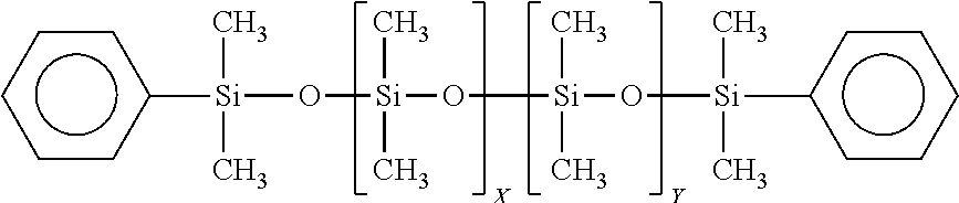
[0140] The precursor may be a di-phenyl terminated siloxane (which may also be referred to as phenyl terminated), which formula is shown below.
##STR00010##
[0141] Where here R is a reactive group, such as vinyl, hydroxy, or hydride. This precursor may have a molecular weight (mw) from about 500 mw to about 2,000 mw, and may have a viscosity preferably from about 80 cps to about 300 cps. The percentage of methyl --R-- siloxane units "X" may be from 1% to 100%. The percentage of the dimethylsiloxane units "Y" may be from 0% to 99%. This precursor may be used to provide a toughening agent, and to adjust the refractive index of the polymer to match the refractive index of various types of glass, to provide for example transparent fiberglass, as well as, other features and characteristics to the cured preform and ceramic material.
[0142] The precursor may be a mono-phenyl terminated siloxane (which may also be referred to as trimethyl terminated, phenyl terminated siloxane), which formulas are shown below.
##STR00011##
[0143] Where R is a reactive group, such as vinyl, hydroxy, or hydride. This precursor may have a molecular weight (mw) from about 500 mw to about 2,000 mw, and may have a viscosity preferably from about 80 cps to about 300 cps. The percentage of methyl --R-- siloxane units "X" may be from 1% to 100%. The percentage of the dimethylsiloxane units "Y" may be from 0% to 99%. This precursor may be used to provide a toughening agent and to adjust the refractive index of the polymer to match the refractive index of various types of glass, to provide for example transparent fiberglass, as well as, other features and characteristics to the cured preform and ceramic material.
[0144] The precursor may be a diphenyl dimethyl polysiloxane, which formula is shown below.
##STR00012##
[0145] This precursor may have a molecular weight (mw) from about 500 mw to about 20,000 mw, and may have a molecular weight from about 800 to about 4,000, and may have a viscosity preferably from about 100 cps to about 800 cps. The percentage of dimethylsiloxane units "X" may be from 25% to 95%. The percentage of the diphenyl siloxane units "Y" may be from 5% to 75%. This precursor may be used to provide similar characteristics to the mono-phenyl terminated siloxane, as well as, other features and characteristics to the cured preform and ceramic material.
[0146] The precursor may be a vinyl terminated diphenyl dimethyl polysiloxane, which formula is shown below.
##STR00013##
[0147] This precursor may have a molecular weight (mw) from about 400 mw to about 20,000 mw, and may have a molecular weight from about 800 to about 2,000, and may have a viscosity preferably from about 80 cps to about 600 cps. The percentage of dimethylsiloxane units "X" may be from 25% to 95%. The percentage of the diphenyl siloxane units "Y" may be from 5% to 75%. This precursor may be used to provide chain extension, toughening agent, changed or altered refractive index, and improvements to high temperature thermal stability of the cured material, as well as, other features and characteristics to the cured preform and ceramic material.
[0148] The precursor may be a hydroxy terminated diphenyl dimethyl polysiloxane, which formula is shown below.
##STR00014##
[0149] This precursor may have a molecular weight (mw) from about 400 mw to about 20,000 mw, and may have a molecular weight from about 800 to about 2,000, and may have a viscosity preferably from about 80 cps to about 400 cps. The percentage of dimethylsiloxane units "X" may be from 25% to 95%. The percentage of the diphenyl siloxane units "Y" may be from 5% to 75%. This precursor may be used to provide chain extension, toughening agent, changed or altered refractive index, and improvements to high temperature thermal stability of the cured material, can generate nano- and micro-scale porosity, as well as other features and characteristics to the cured preform and ceramic material.
[0150] This precursor may be a methyl terminated phenylethyl polysiloxane, (which may also be referred to as styrene vinyl benzene dimethyl polysiloxane), which formula is shown below.
##STR00015##
[0151] This precursor may have a molecular weight (mw) may be from about 800 mw to at least about 10,000 mw to at least about 20,000 mw, and may have a viscosity preferably from about 50 cps to about 350 cps. The percentage of styrene vinyl benzene siloxane units "X" may be from 1% to 60%. The percentage of the dimethylsiloxane units "Y" may be from 40% to 99%. This precursor may be used to provide improved toughness, decreases reaction cure exotherm, may change or alter the refractive index, adjust the refractive index of the polymer to match the refractive index of various types of glass, to provide for example transparent fiberglass, as well as, other features and characteristics to the cured preform and ceramic material.
[0152] The forgoing linear siloxane backbone materials, are by way of example, and it is understood that other similar linear siloxane backbone materials can also be used as precursors. More complex linear and branched siloxane backbone materials may be used as precursors, but are not preferred.
[0153] A variety of cyclosiloxanes can be used as precursors, and are reactive molecules, in the formulation. They can be described by the following nomenclature system or formula: D.sub.xD*.sub.y, where "D" represents a dimethyl siloxy unit and "D*" represents a substituted methyl siloxy unit, where the "*" group could be vinyl, allyl, hydride, hydroxy, phenyl, styryl, alkyl, cyclopentadienyl, or other organic group, x is from 0-8, y is >=1, and x+y is from 3-8. Further, in this nomenclature system--D represents --SiO.sub.2 groups, typically Me.sub.2SiO.sub.2, Q represents SiO.sub.4, T represents --SiO.sub.3 groups, typically MeSiO.sub.3 and M represent --SiO groups, typically Me.sub.3SiO.
[0154] The precursor batch may also: (i) contain non-silicon based precursors, such as non-silicon based cross-linking agents; (ii) be the reaction product of a non-silicon based cross linking agent and a silicon based precursor; and, (iii) combinations and variation of these. The non-silicon based cross-linking agents are intended to, and provide, the capability to cross-link during curing. For example, non-silicon based cross-linking agents include: cyclopentadiene (CP), methylcyclopentadiene (MeCP), dicyclopentadiene (DCPD), methyldicyclopentadiene (MeDCPD), tricyclopentadiene (TCPD), piperylene, divnylbenzene, isoprene, norbornadiene, vinylnorbornene, propenylnorbornene, isopropenylnorbornene, methylvinylnorbornene, bicyclononadiene, methylbicyclononadiene, propadiene, 4-vinylcyclohexene, 1,3-heptadiene, cycloheptadiene, 1,3-butadiene, cyclooctadiene and isomers thereof. Generally, any hydrocarbon that contains two (or more) unsaturated, C.dbd.C, bonds that can react with a Si--H, or other Si bond in a precursor, can be used as a cross-linking agent. Some organic materials containing oxygen, nitrogen, and sulphur may also function as cross-linking agents.
[0155] The amount of the non-silicon based cross-linking agent to the silicon based precursor can be from about 10% to 90% non-silicon based cross-linker to 10% to 90% silicon based precursor (preferably a silicon backbone, e.g., --Si--O-- backbone, material). Thus, the ranges of amounts can be, for example: DCPD/MHF from 10/90 to 90/10, about 40/60 to 60/40, about 50/50, and combinations and variations of these ratios, as well as other ratios. A third and fourth precursor material may also be used. Thus, the ratio of non-silicon cross linker/silicon backbone precursor/third precursor, can be: form about 10% to about 80% non-silicon based cross linker; from about 10% to 80% silicon based precursor: and form about 0.1% to 40% third precursor. The ranges and amounts can be, for example: DCPD/MHF/3rd precursor from about 10/20/70 to 70/20/10, from about 10/20/70 to 10/70/20, from about 45/55/10 to about 55/45/10, from about 40/55/5 to about 55/40/5 and combinations and variations of these ratios as well as other ratios.
[0156] The precursor may be a reactive monomer. These would include molecules, such as tetramethyltetravinylcyclotetrasiloxane (TV), which formula is shown below.
##STR00016##
[0157] This precursor may be used to provide a branching agent, a three-dimensional cross-linking agent, as well as, other features and characteristics to the cured preform and ceramic material. (It is also noted that in certain formulations, e.g., above 2%, and certain temperatures, e.g., about from about room temperature to about 60.degree. C., this precursor may act as an inhibitor to cross-linking, e.g., in may inhibit the cross-linking of hydride and vinyl groups.)
[0158] The precursor may be a reactive monomer, for example, such as trivinyl cyclotetrasiloxane,
##STR00017##
[0159] divinyl cyclotetrasiloxane,
##STR00018##
[0160] trivinyl monohydride cyclotetrasiloxane,
##STR00019##
[0161] divinyl dihydride cyclotetrasiloxane,
##STR00020##
[0162] and a hexamethyl cyclotetrasiloxane, such as,
##STR00021##
[0163] The precursor may be a silane modifier, such as vinyl phenyl methylsilane, diphenylsilane, diphenylmethylsilane, and phenylmethylsilane (some of which may be used as an end capper or end termination group). These silane modifiers can provide chain extenders and branching agents. They also improve toughness, alter refractive index, and improve high temperature cure stability of the cured material, as well as improving the strength of the cured material, among other things. A precursor, such as diphenylmethylsilane, may function as an end capping agent, that may also improve toughness, alter refractive index, and improve high temperature cure stability of the cured material, as well as, improving the strength of the cured material, among other things.
[0164] The precursor may be a reaction product of a silane modifier with a vinyl terminated siloxane backbone additive. The precursor may be a reaction product of a silane modifier with a hydroxy terminated siloxane backbone additive. The precursor may be a reaction product of a silane modifier with a hydride terminated siloxane backbone additive. The precursor may be a reaction product of a silane modifier with TV. The precursor may be a reaction product of a silane. The precursor may be a reaction product of a silane modifier with a cyclosiloxane, taking into consideration steric hindrances. The precursor may be a partially hydrolyzed tertraethyl orthosilicate, such as TES 40 or Silbond 40. The precursor may also be a methylsesquisiloxane such as SR-350 available from Momentive (previously from General Electric Company, Wilton, Conn.). The precursor may also be a phenyl methyl siloxane such as 604 from Wacker Chemie AG. The precursor may also be a methylphenylvinylsiloxane, such as H62 C from Wacker Chemie AG.
[0165] The precursors may also be selected from the following: SiSiB.RTM. HF2020, TRIMETHYLSILYL TERMINATED METHYL HYDROGEN SILICONE FLUID 63148-57-2; SiSiB.RTM. HF2050 TRIMETHYLSILYL TERMINATED METHYLHYDROSILOXANE DIMETHYLSILOXANE COPOLYMER 68037-59-2; SiSiB.RTM. HF2060 HYDRIDE TERMINATED METHYLHYDROSILOXANE DIMETHYLSILOXANE COPOLYMER 69013-23-6; SiSiB.RTM. HF2038 HYDROGEN TERMINATED POLYDIPHENYL SILOXANE; SiSiB.RTM. HF2068 HYDRIDE TERMINATED METHYLHYDROSILOXANE DIMETHYLSILOXANE COPOLYMER 115487-49-5; SiSiB.RTM. HF2078 HYDRIDE TERMINATED POLY(PHENYLDIMETHYLSILOXY) SILOXANE PHENYL SILSESQUIOXANE, HYDROGEN-TERMINATED 68952-30-7; SiSiB.RTM. VF6060 VINYLDIMETHYL TERMINATED VINYLMETHYL DIMETHYL POLYSILOXANE COPOLYMERS 68083-18-1; SiSiB.RTM. VF6862 VINYLDIMETHYL TERMINATED DIMETHYL DIPHENYL POLYSILOXANE COPOLYMER 68951-96-2; SiSiB.RTM. VF6872 VINYLDIMETHYL TERMINATED DIMETHYL-METHYLVINYL-DIPHENYL POLYSILOXANE COPOLYMER; SiSiB.RTM. PC9401 1,1,3,3-TETRAMETHYL-1,3-DIVI NYLDISI LOXANE 2627-95-4; SiSiB.RTM. PF1070 SILANOL TERMINATED POLYDIMETHYLSILOXANE (OF1070) 70131-67-8; SiSiB.RTM. OF1070 SILANOL TERMINATED POLYDIMETHYSILOXANE 70131-67-8; OH-ENDCAPPED POLYDIMETHYLSILOXANE HYDROXY TERMINATED OLYDIMETHYLSILOXANE 73138-87-1; SiSiB.RTM. VF6030 VINYL TERMINATED POLYDIMETHYL SILOXANE 68083-19-2; and, SiSiB.RTM. HF2030 HYDROGEN TERMINATED POLYDIMETHYLSILOXANE FLUID 70900-21-9.
[0166] Thus, in additional to the forgoing type of precursors, it is contemplated that a precursor may be a compound of the following general formula.
##STR00022##
[0167] Wherein end cappers E.sub.1 and E.sub.2 are chosen from groups such as trimethylsilyl (trimethyl silicon) (--Si(CH.sub.3).sub.3), dimethylsilyl hydroxy (dimethyl silicon hydroxy) (--Si(CH.sub.3).sub.2OH), dimethylhydridosilyl (dimethyl silicon hydride) (--Si(CH.sub.3).sub.2H), dimethylvinylsilyl (dimethyl vinyl silicon) (--Si(CH.sub.3).sub.2(CH.dbd.CH.sub.2)), dimethylphenylsily (--Si(CH.sub.3).sub.2(C.sub.6H.sub.5)) and dimethylalkoxysilyl (dimethyl alkoxy silicon) (--Si(CH.sub.3).sub.2(OR). The R groups R.sub.1, R.sub.2, R.sub.3, and R.sub.4 may all be different, or one or more may be the same. Thus, for example, R.sub.2 is the same as R.sub.3, R.sub.3 is the same as R.sub.4, R.sub.1 and R.sub.2 are different with R.sub.3 and R.sub.4 being the same, etc. The R groups are chosen from groups such as hydride (--H), methyl (Me)(--C), ethyl (--C--C), vinyl (--C.dbd.C), alkyl (--R)(C.sub.nH.sub.2n+1), allyl (--C--C.dbd.C), aryl ('R), phenyl (Ph)(--C.sub.6H.sub.5), methoxy (--O--C), ethoxy (--O--C--C), siloxy (--O--Si--R.sub.3), alkoxy (--O--R), hydroxy (--O--H), phenylethyl (--C--C--C.sub.6H.sub.5) and methyl,phenyl-ethyl (--C--C(--C)(--C.sub.6H.sub.5).
[0168] In general, embodiments of formulations for polysilocarb formulations may, for example, have from about 0% to 50% MHF, about 20% to about 99% MHF, about 0% to about 30% siloxane backbone material, about 20% to about 99% siloxane backbone materials, about 0% to about 70% reactive monomers, about 0% to about 95% TV, about 0% to about 70% non-silicon based cross linker, and, about 0% to about 90% reaction products of a siloxane backbone additives with a silane modifier or an organic modifier reaction product.
[0169] In mixing the formulations sufficient time should be used to permit the precursors to become effectively mixed and dispersed. Generally, mixing of about 15 minutes to an hour is sufficient. Typically, the precursor formulations are relatively, and essentially, shear insensitive, and thus the type of pumps or mixing are not critical. It is further noted that in higher viscosity formulations additional mixing time may be required. The temperature of the formulations, during mixing should preferably be kept below about 45.degree. C., and preferably about 10.degree. C. (It is noted that these mixing conditions are for the pre-catalyzed formulations.)
[0170] The Reaction Type Process
[0171] In the reaction type process, in general, a chemical reaction is used to combine one, two or more precursors, typically in the presence of a solvent, to form a precursor formulation that is essentially made up of a single polymer that can then be, catalyzed, cured and pyrolized. This process provides the ability to build custom precursor formulations that when cured can provide plastics having unique and desirable features. The cured materials can also be pyrolized to form ceramics having unique features. The reaction type process allows for the predetermined balancing of different types of functionality in the end product by selecting functional groups for incorporation into the polymer that makes up the precursor formulation, e.g., phenyls which typically are not used for ceramics but have benefits for providing high temperature capabilities for plastics, and styrene which typically does not provide high temperature features for plastics but provides benefits for ceramics.
[0172] In general a custom polymer for use as a precursor formulation is made by reacting precursors in a condensation reaction to form the polymer precursor formulation. This precursor formulation is then cured into a preform, i.e., plastic, cured solid or semi-solid material, through a hydrolysis reaction. The condensation reaction forms a polymer of the type shown below.
##STR00023##
[0173] Where R.sub.1 and R.sub.2 in the polymeric units can be a hydride (--H), a methyl (Me)(--C), an ethyl (--C--C), a vinyl (--C.dbd.C), an alkyl (--R)(C.sub.nH.sub.2n+1), an unsaturated alkyl (--C.sub.nH.sub.2n-1), a cyclic alkyl (--C.sub.nH.sub.2n-1), an allyl (--C--C.dbd.C), a butenyl (--C.sub.4H.sub.7), a pentenyl (--C.sub.5H.sub.9), a cyclopentenyl (--C.sub.5H.sub.7), a methyl cyclopentenyl (--C.sub.5H.sub.6(CH.sub.3)), a norbornenyl (--C.sub.XH.sub.Y, where X=7-15 and Y=9-18), an aryl ('R), a phenyl (Ph)(--C.sub.8H.sub.5), a cycloheptenyl (--C.sub.7H.sub.11), a cyclooctenyl (--C.sub.8H.sub.13), an ethoxy (--O--C--C), a siloxy (--O--Si--R.sub.3), a methoxy (--O--C), an alkoxy, (--O--R), a hydroxy, (--O--H), a phenylethyl (--C--C--C.sub.6H.sub.5) a methyl,phenyl-ethyl (--C--C(--C)(--C.sub.6H.sub.5)) and a vinylphenyl-ethyl (--C--C(C.sub.6H.sub.4(--C.dbd.C))). R.sub.1 and R.sub.2 may be the same or different. The custom precursor polymers can have several different polymeric units, e.g., A.sub.1, A.sub.2, A.sub.n, and may include as many as 10, 20 or more units, or it may contain only a single unit, for example, MHF made by the reaction process may have only a single unit.
[0174] Embodiments may include precursors, which include among others, a triethoxy methyl silane, a diethoxy methyl phenyl silane, a diethoxy methyl hydride silane, a diethoxy methyl vinyl silane, a dimethyl ethoxy vinyl silane, a diethoxy dimethyl silane. an ethoxy dimethyl phenyl silane, a diethoxy dihydride silane, a triethoxy phenyl silane, a diethoxy hydride trimethyl siloxane, a diethoxy methyl trimethyl siloxane, a trimethyl ethoxy silane, a diphenyl diethoxy silane, a dimethyl ethoxy hydride siloxane, and combinations and variations of these and other precursors, including other precursors set forth in this specification.
[0175] The end units, Si End 1 and Si End 2, can come from the precursors of dimethyl ethoxy vinyl silane, ethoxy dimethyl phenyl silane, and trimethyl ethoxy silane. Additionally, if the polymerization process is properly controlled a hydroxy end cap can be obtained from the precursors used to provide the repeating units of the polymer.
[0176] In general, the precursors are added to a vessel with ethanol (or other material to absorb heat, e.g., to provide thermal mass), an excess of water, and hydrochloric acid (or other proton source). This mixture is heated until it reaches its activation energy, after which the reaction typically is exothermic. Generally, in this reaction the water reacts with an ethoxy group of the silane of the precursor monomer, forming a hydroxy (with ethanol as the byproduct). Once formed this hydroxy becomes subject to reaction with an ethoxy group on the silicon of another precursor monomer, resulting in a polymerization reaction. This polymerization reaction is continued until the desired chain length(s) is built.
[0177] Control factors for determining chain length, among others, are: the monomers chosen (generally, the smaller the monomers the more that can be added before they begin to coil around and bond to themselves); the amount and point in the reaction where end cappers are introduced; and the amount of water and the rate of addition, among others. Thus, the chain lengths can be from about 180 mw (viscosity about 5 cps) to about 65,000 mw (viscosity of about 10,000 cps), greater than about 1000 mw, greater than about 10,000 mw, greater than about 50,000 mw and greater. Further, the polymerized precursor formulation may, and typically does, have polymers of different molecular weights, which can be predetermined to provide formulation, cured, and ceramic product performance features.
[0178] Upon completion of the polymerization reaction the material is transferred into a separation apparatus, e.g., a separation funnel, which has an amount of deionized water that, for example, is from about 1.2.times. to about 1.5.times. the mass of the material. This mixture is vigorously stirred for about less than 1 minute and preferably from about 5 to 30 seconds. Once stirred the material is allowed to settle and separate, which may take from about 1 to 2 hours. The polymer is the higher density material and is removed from the vessel. This removed polymer is then dried by either warming in a shallow tray at 90.degree. C. for about two hours; or, preferably, is passed through a wiped film distillation apparatus, to remove any residual water and ethanol. Alternatively, sodium bicarbonate sufficient to buffer the aqueous layer to a pH of about 4 to about 7 is added. It is further understood that other, and commercial, manners of mixing, reacting and separating the polymer from the material may be employed.
[0179] Preferably a catalyst is used in the curing process of the polymer precursor formulations from the reaction type process. The same polymers, as used for curing the precursor formulations from the mixing type process can be used. It is noted that, generally unlike the mixing type formulations, a catalyst is not necessarily required to cure a reaction type polymer. Inhibitors may also be used. However, if a catalyst is not used, reaction time and rates will be slower. The curing and the pyrolysis of the cured material from the reaction process is essentially the same as the curing and pyrolysis of the cured material from the mixing process and the reaction blending process.
[0180] The reaction type process can be conducted under numerous types of atmospheres and conditions, e.g., air, inert, N.sub.2, Argon, flowing gas, static gas, reduced pressure, ambient pressure, elevated pressure, and combinations and variations of these.
[0181] The Reaction Blending Type Process
[0182] In the reaction blending type process precursor are reacted to from a precursor formulation, in the absence of a solvent. For example, an embodiment of a reaction blending type process has a precursor formulation that is prepared from MHF and Dicyclopentadiene (DCPD). Using the reactive blending process a MHF/DCPD polymer is created and this polymer is used as a precursor formulation. It can be used alone to form a cured or pyrolized product, or as a precursor in the mixing or reaction processes.
[0183] Thus, for example, from about 40 to 90% MHF of known molecular weight and hydride equivalent mass; about 0.20 wt % P01 catalyst; and from about 10 to 60% DCPD with 83% purity, can be used.
[0184] P01 is a 2% Pt(0) tetravinylcyclotetrasiloxane complex in tetravinylcyclotetrasiloxane, diluted 20.times. with tetravinylcyclotetrasiloxane to 0.1% of Pt(0) complex. In this manner 10 ppm Pt is provided for every 1% loading of bulk cat.
[0185] In an embodiment of the process, a sealable reaction vessel, with a mixer, can be used for the reaction. The reaction is conducted in the sealed vessel, in air; although other types of atmosphere can be utilized. Preferably, the reaction is conducted at atmospheric pressure, but higher and lower pressures can be utilized. Additionally, the reaction blending type process can be conducted under numerous types of atmospheres and conditions, e.g., air, inert, N.sub.2, Argon, flowing gas, static gas, reduced pressure, ambient pressure, elevated pressure, and combinations and variations of these.
[0186] In an embodiment, 850 grams of MHF (85% of total polymer mixture) is added to reaction vessel and heated to about 50.degree. C. Once this temperature is reached the heater is turned off, and 0.20% (by weight of the MHF) of P01 Platinum catalyst is added to the MHF in the reaction vessel. Typically, upon addition of the catalyst, bubbles will form and temperature will initially rise approximately 2-20.degree. C.
[0187] When the temperature begins to fall, about 150 g of DCPD (15 wt % of total polymer mixture) is added to the reaction vessel. The temperature may drop an additional amount, e.g., around 5-7.degree. C.
[0188] At this point in the reaction process the temperature of the reaction vessel is controlled to, maintain a predetermined temperature profile over time, and to manage the temperature increase that may be accompanied by an exotherm. Preferably, the temperature of the reaction vessel is regulated, monitored and controlled throughout the process.
[0189] In an embodiment of the MHF/DCPD embodiment of the reaction process, the temperature profile can be as follows: let temperature reach about 80.degree. C. (may take .about.15-40 min, depending upon the amount of materials present); temperature will then increase and peak at .about.104.degree. C., as soon as temperature begins to drop, the heater set temperature is increased to 100.degree. C. and the temperature of the reaction mixture is monitored to ensure the polymer temperature stays above 80.degree. C. for a minimum total of about 2 hours and a maximum total of about 4 hours. After 2-4 hours above 80.degree. C., the heater is turn off, and the polymer is cooled to ambient. It being understood that in larger and smaller batches, continuous, semi-continuous, and other type processes the temperature and time profile may be different.
[0190] In larger scale, and commercial operations, batch, continuous, and combinations of these, may be used. Industrial factory automation and control systems can be utilized to control the reaction, temperature profiles and other processes during the reaction.
[0191] Table A sets forth various embodiments of precursor materials.
TABLE-US-00002 TABLE A degree of Equivalents Equivalents Equivalents Equivalents Equivalents Equivalents grams/mole Material Name polymerization Si/mole O/mole H/mol Vi/mol methyl/mole C/mole MW of vinyl tetramethylcyclotet 4 4 4 4 0 4 4 240.51 rasiloxane (D.sub.4) MHF 33 35 34 33 0 39 39 2145.345 VMF 5 7 6 0 5 11 21 592.959 118.59 TV 4 4 4 0 4 4 12 344.52 86.13 VT 0200 125 127 126 0 2 254 258 9451.206 4725.60 VT 0020 24 26 25 0 2 52 56 1965.187 982.59 VT 0080 79 81 80 0 2 162 166 6041.732 3020.87 Styrene 2 104.15 52.08 Dicyclopentadiene 2 132.2 66.10 1,4-divinylbenzene 2 130.19 65.10 isoprene 2 62.12 31.06 1,3 Butadiene 2 54.09 27.05 Catalyst 10 ppm Pt Catalyst LP 231
[0192] In the above table, the "degree of polymerization" is the number of monomer units, or repeat units, that are attached together to from the polymer. "Equivalents_/mol" refers to the molar equivalents. "Grams/mole of vinyl" refers to the amount of a given polymer needed to provide 1 molar equivalent of vinyl functionality. "VMH" refers to methyl vinyl fluid, a linear vinyl material from the ethoxy process, which can be a substitute for TV. The numbers "0200" etc. for VT are the viscosity (e.g., 0200=200 cps) in centipoise for that particular VT.
[0193] Curing and Pyrolysis
[0194] Precursor formulations, including the polysilocarb precursor formulations from the above types of processes, as well as others, can be cured to form a solid, semi-sold, or plastic like material. Typically, the precursor formulations are spread, shaped, or otherwise formed into a preform, which would include any volumetric structure, or shape, including thin and thick films. In curing, the polysilocarb precursor formulation may be processed through an initial cure, to provide a partially cured material, which may also be referred to, for example, as a preform, green material, or green cure (not implying anything about the material's color). The green material may then be further cured. Thus, one or more curing steps may be used. The material may be "end cured," i.e., being cured to that point at which the material has the necessary physical strength and other properties for its intended purpose. The amount of curing may be to a final cure (or "hard cure"), i.e., that point at which all, or essentially all, of the chemical reaction has stopped (as measured, for example, by the absence of reactive groups in the material, i.e., all of the reaction has stopped, or the leveling off of the decrease in reactive groups over time, i.e., essentially all of the reaction has stopped). Thus, the material may be cured to varying degrees, depending upon its intended use and purpose. For example, in some situations the end cure and the hard cure may be the same. Curing conditions such as atmosphere and temperature may effect the composition of the cured material.
[0195] In multi-layer, or composite structures and shapes, a layer of the polysilocarb material may be cured to varying degrees, for example in a multi-layer embodiment, the layers can be green cured to promote layer adhesion, then finally cured to a hard cure. Each layer in a multi-layer structure can be cured to the same degree of cure, to different degrees of cure, subject to one, two, three or more curing steps, and combinations and variations of these.
[0196] The curing may be done at standard ambient temperature and pressure ("SATP", 1 atmosphere, 25.degree. C.), at temperatures above or below that temperature, at pressures above or below that pressure, and over varying time periods. The curing can be conducted over various heatings, rate of heating, and temperature profiles (e.g., hold times and temperatures, continuous temperature change, cycled temperature change, e.g., heating followed by maintaining, cooling, reheating, etc.). The time for the curing can be from a few seconds (e.g., less than about 1 second, less than 5 seconds), to less than a minute, to minutes, to hours, to days (or potentially longer). The curing may also be conducted in any type of surrounding environment, including for example, gas, liquid, air, water, surfactant containing liquid, inert atmospheres, N.sub.2, Argon, flowing gas (e.g., sweep gas), static gas, reduced O.sub.2 (e.g., an amount of O.sub.2 lower than atmospheric, such as less than 20% O.sub.2, less than 15% O.sub.2, less than 10% O.sub.2 less than 5% 02), reduced pressure (e.g., less than atmospheric), elevated pressure (e.g., greater than atmospheric), enriched O.sub.2, (e.g., an amount of 02 greater than atmospheric), ambient pressure, controlled partial pressure and combinations and variations of these and other processing conditions.
[0197] In an embodiment, the curing environment, e.g., the furnace, the atmosphere, the container and combinations and variations of these can have materials that contribute to or effect, for example, the composition, catalysis, stoichiometry, features, performance and combinations and variations of these in the preform, the cured material, the ceramic and the final applications or products.
[0198] For high purity materials, the furnace, containers, handling equipment, atmosphere, and other components of the curing apparatus and process are clean, essentially free from, and do not contribute any elements or materials, that would be considered impurities or contaminants, to the cured material.
[0199] Preferably, in embodiments of the curing process, the curing takes place at temperatures in the range of from about 5.degree. C. or more, from about 20.degree. C. to about 250.degree. C., from about 20.degree. C. to about 150.degree. C., from about 75.degree. C. to about 125.degree. C., and from about 80.degree. C. to 90.degree. C. Although higher and lower temperatures and various heating profiles, (e.g., rate of temperature change over time ("ramp rate", e.g., A degrees/time), hold times, and temperatures) can be utilized.
[0200] The cure conditions, e.g., temperature, time, ramp rate, may be dependent upon, and in some embodiments can be predetermined, in whole or in part, by the formulation to match, for example the size of the preform, the shape of the preform, or the mold holding the preform to prevent stress cracking, off gassing, or other phenomena associated with the curing process. Further, the curing conditions may be such as to take advantage of, preferably in a controlled manner, what may have previously been perceived as problems associated with the curing process. Thus, for example, off gassing may be used to create a foam material having either open or closed structure. Similarly, curing conditions can be used to create or control the microstructure and the nanostructure of the material. In general, the curing conditions can be used to affect, control or modify the kinetics and thermodynamics of the process, which can affect morphology, performance, features and functions, among other things.
[0201] Upon curing the polysilocarb precursor formulation a cross linking reaction takes place that provides in some embodiments a cross-linked structure having, among other things, by way of example, an --R.sub.1--Si--C--C--Si--O--Si--C--C--Si--R.sub.2-- where R.sub.1 and R.sub.2 vary depending upon, and are based upon, the precursors used in the formulation. In an embodiment of the cured materials they may have a cross-linked structure having 3-coordinated silicon centers to another silicon atom, being separated by fewer than 5 atoms between silicon atoms. Although additional other structures and types of cured materials are contemplated. Thus, for example, use of Luperox 231 could yield a structure, from the same monomers, that was --Si--C--C--C--Si--. When other cross linking agents are used, e.g, DCPD and divinyl benzene, the number of carbons atoms between the silicon atoms will be greater than 5 atoms. A generalized formula for some embodiments of the cross-linked, e.g., cured, material, would be --Si--R.sub.3--Si--, where R.sub.3 would be ethyl (from for example a vinyl precursor), propyl (from for example a allyl precursor), dicyclopentane (from for example a DCPD precursor), norbornane (from for example a norbornadiene precursor), diethylbenzene (from for example a divinyl benzene precursor), and others.
[0202] During the curing process, some formulations may exhibit an exotherm, i.e., a self heating reaction, that can produce a small amount of heat to assist or drive the curing reaction, or that may produce a large amount of heat that may need to be managed and removed in order to avoid problems, such as stress fractures. During the cure off gassing typically occurs and results in a loss of material, which loss is defined generally by the amount of material remaining, e.g., cure yield. Embodiments of the formulations, cure conditions, and polysilocarb precursor formulations of embodiments of the present inventions can have cure yields of at least about 90%, about 92%, about 100%. In fact, with air cures the materials may have cure yields above 100%, e.g., about 101-105%, as a result of oxygen being absorbed from the air. Additionally, during curing the material typically shrinks, this shrinkage may be, depending upon the formulation, cure conditions, and the nature of the preform shape, and whether the preform is reinforced, filled, neat or unreinforced, from about 20%, less than 20%, less than about 15%, less than about 5%, less than about 1%, less than about 0.5%, less than about 0.25% and smaller.
[0203] Curing may be accomplished by any type of heating apparatus, or mechanisms, techniques, or morphologies that has the requisite level of temperature and environmental control. Curing may be accomplished through, for example, heated water baths, electric furnaces, microwaves, gas furnaces, furnaces, forced heated air, towers, spray drying, falling film reactors, fluidized bed reactors, indirect heating elements, direct heating (e.g., heated surfaces, drums, and plates), infrared heating, UV irradiation (light), an RF furnace, in-situ during emulsification via high shear mixing, in-situ during emulsification via ultrasonication, broad spectrum white light, IR light, coherent electromagnetic radiation (e.g. lasers, including visible, UV and IR), and convection heating, to name a few.
[0204] In an embodiment, curing may also occur under ambient conditions for an embodiment having a sufficient amount of catalyst.
[0205] If pyrolysis is conducted for an embodiment the cured material can be for example heated to about 600.degree. C. to about 2,300.degree. C.; from about 650.degree. C. to about 1,200.degree. C., from about 800.degree. C. to about 1300.degree. C., from about 900.degree. C. to about 1,200.degree. C. and from about 950.degree. C. to 1,150.degree. C. At these temperatures typically all organic structures are either removed or combined with the inorganic constituents to form a ceramic. Typically, at temperatures in the about 650.degree. C. to 1,200.degree. C. range the resulting material is an amorphous glassy ceramic. When heated above about 1,200.degree. C. the material typically may from nano crystalline structures, or micro crystalline structures, such as SiC, Si.sub.3N.sub.4, SiCN, .beta. SiC, and above 1,900.degree. C. an a SiC structure may form, and at and above 2,200.degree. C. a SiC is typically formed. The pyrolized, e.g., ceramic materials can be single crystal, polycrystalline, amorphous, and combinations, variations and subgroups of these and other types of morphologies.
[0206] The pyrolysis may be conducted under may different heating and environmental conditions, which preferably include thermo control, kinetic control and combinations and variations of these, among other things. For example, the pyrolysis may have various heating ramp rates, heating cycles and environmental conditions. In some embodiments, the temperature may be raised, and held a predetermined temperature, to assist with known transitions (e.g., gassing, volatilization, molecular rearrangements, etc.) and then elevated to the next hold temperature corresponding to the next known transition. The pyrolysis may take place in reducing atmospheres, oxidative atmospheres, low O.sub.2, gas rich (e.g., within or directly adjacent to a flame), inert, N.sub.2, Argon, air, reduced pressure, ambient pressure, elevated pressure, flowing gas (e.g., sweep gas, having a flow rate for example of from about from about 15.0 GHSV (gas hourly space velocity) to about 0.1 GHSV, from about 6.3 GHSV to about 3.1 GHSV, and at about 3.9 GHSV), static gas, and combinations and variations of these.
[0207] In some embodiments, upon pyrolization, graphenic, graphitic, amorphous carbon structures and combinations and variations of these are present in the Si--O--C ceramic. A distribution of silicon species, consisting of SiOxCy structures, which result in SiO.sub.4, SiO.sub.3C, SiO.sub.2C.sub.2, SiOC.sub.3, and SiC.sub.4 are formed in varying ratios, arising from the precursor choice and their processing history. Carbon is generally bound between neighboring carbons and/or to a Silicon atom. In general, in the ceramic state, carbon is largely not coordinated to an oxygen atom, thus oxygen is largely coordinated to silicon
[0208] The pyrolysis may be conducted in any heating apparatus, that maintains the request temperature and environmental controls. Thus, for example pyrolysis may be done with, pressure furnaces, box furnaces, tube furnaces, crystal-growth furnaces, graphite box furnaces, arc melt furnaces, induction furnaces, kilns, MoSi.sub.2 heating element furnaces, carbon furnaces, vacuum furnaces, gas fired furnaces, electric furnaces, direct heating, indirect heating, fluidized beds, RF furnaces, kilns, tunnel kilns, box kilns, shuttle kilns, coking type apparatus, lasers, microwaves, other electromagnetic radiation, and combinations and variations of these and other heating apparatus and systems that can obtain the request temperatures for pyrolysis.
[0209] In embodiments of the polysilocarb derived ceramic materials has any of the amounts of Si, O, C for the total amount of material that are set forth in the Table B.
TABLE-US-00003 TABLE B Si O C Lo Hi Lo Hi Lo Hi Wt % 35.00% 50.00% 10.00% 35.00% 5.00% 30.00% Mole 1.000 1.429 0.502 1.755 0.334 2.004 Ratio Mole 15.358% 63.095% 8.821% 56.819% 6.339% 57.170% %
[0210] In general, embodiments of the pyrolized ceramic polysilocarb materials can have about 20% to about 65% Si, can have about 5% to about 50% 0, and can have about 3% to about 55% carbon weight percent. Greater and lesser amounts are also contemplated.
[0211] In general, embodiment of the pyrolized ceramic polysilocarb materials can have a mole ratio (based on total Si, 0, and C) of about 0.5 to about 2.5 for Si, can have a mole ratio of about 0.2 to about 2.5 for 0, and can have a mole ration of about 0.1 to about 4.5 for C. Greater and lesser amounts are also contemplated.
[0212] In general, embodiment of the pyrolized ceramic polysilocarb materials can have a mole % (percentage of total Si, 0, and C) of about 13% to about 68% for Si, can have a mole % of about 6% to about 60% for 0, and can have a mole % of about 4% to about 75% for C. Greater and lesser amounts are also contemplated.
[0213] The type of carbon present in embodiments of the polysilocarb derived ceramic pigments can be free carbon, (e.g., turbostratic, amorphous, graphenic, graphitic forms of carbon) and carbon that is bound to silicon. Embodiments of ceramic polysilocarb materials having free carbon and silicon-bound-carbon (Si--C) are set forth in Table C. Greater and lesser amounts and different percentages of free carbon and silicon-bound-carbon are also contemplated.
TABLE-US-00004 TABLE C Embodiment % Free Carbon % Si--C type 1 64.86 35.14 2 63.16 36.85 3 67.02 32.98 4 58.59 41.41 5 68.34 31.66 6 69.18 30.82 7 65.66 34.44 8 72.74 27.26 9 72.46 27.54 10 78.56 21.44
[0214] Generally, embodiments of polysilocarb derived ceramic materials can have from about 30% free carbon to about 70% free carbon, from about 20% free carbon to about 80% free carbon, and from about 10% free carbon to about 90% free carbon, and from about 30% Si--C bonded carbon to about 70% Si--C bonded carbon, from about 20% Si--C bonded carbon to about 80% Si--C bonded carbon, and from about 10% Si--C bonded carbon to about 90% Si--C bonded carbon. Greater and lesser amounts are also contemplated.
[0215] Metals and Metal Complexes
[0216] By way of example, metals and metal complexes that can be used as fill material would include Cyclopentadienyl compounds of the transition metals can be utilized. Cyclopentadienyl compounds of the transition metals can be organized into two classes: Bis-cyclopentadienyl complexes; and Monocyclopentadienyl complexes. Cyclopentadienyl complexes can include C.sub.5H.sub.5, C.sub.5Me.sub.5, C.sub.5H.sub.4Me, CH.sub.5R.sub.5 (where R=Me, Et, Propyl, i-Propyl, butyl, Isobutyl, Sec-butyl). In either of these cases Si can be directly bonded to the Cyclopentadienyl ligand or the Si center can be attached to an alkyl chain, which in turn is attached to the Cyclopentadienyl ligand.
[0217] Cyclopentadienyl complexes, that can be utilized with precursor formulations and in products, can include: bis-cyclopentadienyl metal complexes of first row transition metals (Titanium, Vanadium, Chromium, Iron, Cobalt, Nickel); second row transition metals (Zirconium, Molybdenum, Ruthenium, Rhodium, Palladium); third row transition metals (Hafnium, Tantalum, Tungsten, Iridium, Osmium, Platinum); Lanthanide series (La, Ce, Pr, Nd, Pm, Sm, Eu, Gd, Tb, Dy, Ho); and Actinide series (Ac, Th, Pa, U, Np).
[0218] Monocyclopentadienyl complexes may also be utilized to provide metal functionality to precursor formulations and would include monocyclopentadienyl complexes of: first row transition metals (Titanium, Vanadium, Chromium, Iron, Cobalt, Nickel); second row transition metals (Zirconium, Molybdenum, Ruthenium, Rhodium, Palladium); third row transition metals (Hafnium, Tantalum, Tungsten, Iridium, Osmium, Platinum) when preferably stabilized with proper ligands, (for instance Chloride or Carbonyl).
[0219] Alkyl complexes of metals may also be used to provide metal functionality to precursor formulations and products. In these alkyl complexes the Si center has an alkyl group (ethyl, propyl, butyl, vinyl, propenyl, butenyl) which can bond to transition metal direct through a sigma bond. Further, this would be more common with later transition metals such as Pd, Rh, Pt, Ir.
[0220] Coordination complexes of metals may also be used to provide metal functionality to precursor formulations and products. In these coordination complexes the Si center has an unsaturated alkyl group (vinyl, propenyl, butenyl, acetylene, butadienyl) which can bond to carbonyl complexes or ene complexes of Cr, Mo, W, Mn, Re, Fe, Ru, Os, Co, Rh, Ir, Ni. The Si center may also be attached to a phenyl, substituted phenyl or other aryl compound (pyridine, pyrimidine) and the phenyl or aryl group can displace carbonyls on the metal centers.
[0221] Metal alkoxides may also be used to provide metal functionality to precursor formulations and products. Metal alkoxide compounds can be mixed with the silicon precursor compounds and then treated with hydroxide to form the oxides at the same time as the polymer, copolymerizes. This can also be done with metal halides and metal amides. Preferably, this may be done using early transition metals along with Aluminum, Gallium and Indium, later transition metals: Fe, Mn, Cu, and alkaline earth metals: Ca, Sr, Ba, Mg.
[0222] Compounds where Si is directly bonded to a metal center which is stabilized by halide or organic groups may also be utilized to provide metal functionality to precursor formulations and products.
[0223] Additionally, it should be understood that the metal and metal complexes may be the continuous phase after pyrolysis, or subsequent heat treatment. Formulations can be specifically designed to react with selected metals to in situ form metal carbides, oxides and other metal compounds, generally known as cermets (e.g., ceramic metallic compounds). The formulations can be reacted with selected metals to form in situ compounds such as mullite, alumino silicate, and others. The amount of metal relative to the amount of silica in the formulation or end product can be from about 0.1 mole % to 99.9 mole %, about 1 mole % or greater, about 10 mole % or greater, and about 20 mole percent or greater. The forgoing use of metals with the present precursor formulas can be used to control and provide predetermined stoichiometries.
Overview--Water-Soluble Packaging, Films and Resins
[0224] Water-Soluble Films
[0225] Polymer resins described herein (and as set forth in the Table of FIG. 15) can be used to make a water-soluble film. The film can include any suitable amount of resin content; for example, an amount in a range of about 1 wt. % to about 99 wt. %, or 35 wt % to about 90 wt % based on the total weight of the film, or in a range of about 55 to about 95%, or about 60% to 90%, or about 65% to about 85%, or at least 50%.
[0226] PVOH Resins
[0227] The water-soluble film may include one or more polyvinyl alcohol (PVOH) resins disclosed herein to make up the PVOH resin content of the film, and can include a PVOH copolymer resin.
[0228] Polyvinyl alcohol is a synthetic resin generally prepared by the alcoholysis, usually termed hydrolysis or saponification, of polyvinyl acetate. Fully hydrolyzed PVOH, where virtually all the acetate groups have been converted to alcohol groups, is a strongly hydrogen-bonded, highly crystalline polymer which dissolves only in hot water-greater than about 140.degree. F. (about 60.degree. C.). If a sufficient number of acetate groups are allowed to remain after the hydrolysis of polyvinyl acetate, that is, the PVOH polymer is partially hydrolyzed, then the polymer is more weakly hydrogen-bonded, less crystalline, and is generally soluble in cold water less than about 50.degree. F. (about 10.degree. C.). As such, the partially hydrolyzed polymer is a vinyl alcohol-vinyl acetate copolymer that is a PVOH copolymer, but is commonly referred to as homopolymer PVOH.
[0229] The PVOH resin may include a partially or fully hydrolyzed PVOH copolymer that includes an anionic monomer unit, a vinyl alcohol monomer unit, and optionally a vinyl acetate monomer unit. In various embodiments, the anionic monomer can be one or more of vinyl acetic acid, alkyl acrylates, maleic acid, monoalkyl maleate, dialkyl maleate, monomethyl maleate, dimethyl maleate, maleic anhydride, fumaric acid, monoalkyl fumarate, dialkyl fumarate, monomethyl fumarate, dimethyl fumarate, fumaric anhydride, itaconic acid, monomethyl itaconate, dimethyl itaconate, itaconic anhydride, citraconic acid, monoalkyl citraconate, dialkyl citraconate, citraconic anhydride, mesaconic acid, monoalkyl mesaconate, dialkyl mesaconate, mesaconic anhydride, glutaconic acid, monoalkyl glutaconate, dialkyl glutaconate, glutaconic anhydride, vinyl sulfonic acid, alkyl sulfonic acid, ethylene sulfonic acid, 2-acrylamido-1-methyl propane sulfonic acid, 2-acrylamide-2-methylpropanesulfonic acid, 2-methylacrylamido-2-methylpropanesulfonic acid, 2-sulfoethyl acrylate, alkali metal salts of the foregoing (e.g., sodium, potassium, or other alkali metal salts), esters of the foregoing (e.g., methyl, ethyl, or other C.sub.1-C.sub.4 or C.sub.6 alkyl esters), and combinations of the foregoing (e.g., multiple types of anionic monomers or equivalent forms of the same anionic monomer). For example, the anionic monomer can include one or more of monomethyl maleate and alkali metal salts thereof (e.g. sodium salts).
[0230] The total PVOH resin content of the film can have a degree of hydrolysis (D.H. or DH) of at least 80%, 84%, or 85% and at most about 99.7%, 98%, or 96%, for example in a range of about 84% to about 90%, or 85% to 88%, or 86.5%, or in a range of 85% to 99.7%, about 88% to 98%, or 90% to 96%, for example, 91%, 92%, 93%, 94%, 95%, or 96%. As used herein, the degree of hydrolysis is expressed as a mole percentage of vinyl acetate units converted to vinyl alcohol units.
[0231] The viscosity of a PVOH polymer (p) is determined by measuring a freshly made solution using a Brookfield LV type viscometer with UL adapter as described in British Standard ENISO 15023-2:2006 Annex E Brookfield Test method. It is international practice to state the viscosity of 4% aqueous polyvinyl alcohol solutions at 20.degree. C. All viscosities specified herein in Centipoise (cP) should be understood to refer to the viscosity of 4% aqueous polyvinyl alcohol solution at 20.degree. C., unless specified otherwise. Similarly, when a resin is described as having (or not having) a particular viscosity, unless specified otherwise, it is intended that the specified viscosity is the average viscosity for the resin, which inherently has a corresponding molecular weight distribution. Suitable PVOH resins, for use individually or in combinations, can have viscosities in a range of about 1 cP to about 40 cP, or about 5 cP to about 38 cP, or about 10 cP to about 36 cP, or about 12 cP to about 34 cP, or about 14 cP to about 32 cP, for example 32 cP, 23 cP, or 20 cP, or 16.5 cP.
[0232] Additional Water-Soluble Polymers
[0233] The water-soluble film can include water-soluble polymers in addition to the resin described herein. The additional water-soluble polymers can include, but are not limited to, PVOH homopolymer, polyacrylates, water-soluble acrylate copolymers, polyvinyl pyrrolidone, polyethyleneimine, pullulan, water-soluble natural polymers including, but not limited to, guar gum, gum Acacia, xanthan gum, carrageenan, and starch, water-soluble polymer modified starches, copolymers of the forgoing and combinations of any of the foregoing. Yet other water-soluble polymers can include polyalkylene oxides, polyacrylamides, polyacrylic acids and salts thereof, celluloses, cellulose ethers, cellulose esters, cellulose amides, polyvinyl acetates, polycarboxylic acids and salts thereof, polyaminoacids, polyamides, gelatines, methylcelluloses, carboxymethylcelluloses and salts thereof, dextrins, ethylcelluloses, hydroxyethyl celluloses, hydroxypropyl methylcelluloses, maltodextrins, polymethacrylates, and combinations of any of the foregoing. Such water-soluble polymers, whether PVOH or otherwise, are commercially available from a variety of sources.
[0234] Secondary Ingredients
[0235] The water-soluble film including the resin disclosed herein can contain other auxiliary agents and processing agents, such as, but not limited to, plasticizers, plasticizer compatibilizers, surfactants, lubricants, release agents, fillers, extenders, cross-linking agents, antiblocking agents, antioxidants, detackifying agents, antifoams, nanoparticles such as layered silicate-type nanoclays (e.g., sodium montmorillonite), bleaching agents (e.g., sodium metabisulfite, sodium bisulfite or others), aversive agents such as bitterants (e.g., denatonium salts such as denatonium benzoate, denatonium saccharide, and denatonium chloride; sucrose octaacetate; quinine; flavonoids such as quercetin and naringen; and quassinoids such as quassin and brucine) and pungents (e.g., capsaicin, piperine, allyl isothiocyanate, and resinferatoxin), and other functional ingredients, in amounts suitable for their intended purposes. Embodiments including plasticizers are preferred. In embodiments, the water-soluble film includes a surfactant, an antioxidant, a bittering agent, a soil release polymer, an anti-redeposition aid, a chelant, a builder, a perfume, or combinations thereof. The amount of auxiliary agents can be, for example, up to about 50 wt. %, 20 wt %, 15 wt %, 10 wt %, 5 wt. %, 4 wt % and/or at least 0.01 wt. %, 0.1 wt %, 1 wt %, or 5 wt %, individually or collectively.
[0236] Plasticizers
[0237] A plasticizer is a liquid, solid, or semi-solid that is added to a material (usually a resin or elastomer) making that material softer, more flexible (by decreasing the glass-transition temperature of the polymer), and easier to process. A polymer can alternatively be internally plasticized by chemically modifying the polymer or monomer. In addition or in the alternative, a polymer can be externally plasticized by the addition of a suitable plasticizing agent.
[0238] The plasticizer can include, but is not limited to, glycerol, diglycerin, sorbitol, ethylene glycol, diethylene glycol, triethylene glycol, dipropylene glycol, tetraethylene glycol, propylene glycol, polyethylene glycols up to 400 MW, hexylene glycol, neopentyl glycol, trimethylolpropane, polyether polyols, polyether diol, polyether triol, xylitol, 2-methyl-1,3-propanediol (MPDiol.RTM.), ethanolamines, glycerol propylene oxide polymers (such as, for example, Voranol.TM. available from The Dow Chemical Company), and a mixture thereof.
[0239] The total amount of the plasticizer can be in a range of about 10 wt. % to about 45 wt. %, or about 15 wt. % to about 35 wt. %, or about 20 wt. % to about 30 wt. %, or about 20 wt. % to about 45 wt. %, for example about 25 wt. %, based on total film weight. Specific amounts of plasticizers can be selected in a particular embodiment based on factors described herein, including desired film flexibility and conversion features of the water-soluble film. At low plasticizer levels, films may become brittle, difficult to process, or prone to breaking. At elevated plasticizer levels, films may be too soft, weak, or difficult to process for a desired use.
[0240] Surfactants
[0241] Surfactants for use in water-soluble films are well known in the art. Optionally, surfactants are included to aid in the dispersion of the resin solution upon casting to form a film. Suitable surfactants can include the nonionic, cationic, anionic and zwitterionic classes. Suitable surfactants include, but are not limited to, propylene glycols, diethylene glycols, monoethanolamine, polyoxyethylenated polyoxypropylene glycols, alcohol ethoxylates, alkylphenol ethoxylates, tertiary acetylenic glycols and alkanolamides (nonionics), polyoxyethylenated amines, quaternary ammonium salts and quaternized polyoxyethylenated amines (cationics), alkali metal salts of higher fatty acids containing about 8 to 24 carbon atoms, alkyl sulfates, alkyl polyethoxylate sulfates and alkylbenzene sulfonates (anionics), and amine oxides, N-alkylbetaines and sulfobetaines (zwitterionics). Other suitable surfactants include dialkyl sulfosuccinates, lactylated fatty acid esters of glycerin and propylene glycol, lactylic esters of fatty acids, sodium alkyl sulfates, polysorbate 20, polysorbate 60, polysorbate 65, polysorbate 80, alkyl polyethylene glycol, lecithin, acetylated fatty acid esters of glycerin and propylene glycol, sodium lauryl sulfate, acetylated esters of fatty acids, myristyl dimethylamine oxide, trimethyl tallow alkyl ammonium chloride, quaternary ammonium compounds, salts thereof and combinations of any of the foregoing. In embodiments, the surfactant is selected from the group consisting of polyoxyethylenated polyoxypropylene glycols, alcohol ethoxylates, alkylphenol ethoxylates, tertiary acetylenic glycols and alkanolamides, polyoxyethylenated amines, quaternary ammonium salts and quaternized polyoxyethylenated amines, and amine oxides, N-alkylbetaines, sulfobetaines, and combinations thereof.
[0242] In various embodiments, the amount of surfactant in the water-soluble film is in a range of about 0.1 wt % to about 8.0 wt %, or about 1.0 wt % to about 7.0 wt %, or about 3 wt % to about 7 wt %, or about 5 wt % to about 7 wt %, or about 0.1 wt. % to 2.5 wt %. Too little surfactant can sometimes result in a cast film having holes, whereas too much surfactant can result in the film having a greasy or oily feel from excess surfactant present on the surface of the film.
[0243] Lubricants/Release Agents
[0244] Suitable lubricants/release agents for use in the water-soluble films described herein can include, but are not limited to, fatty acids and their salts, fatty alcohols, fatty esters, fatty amines, fatty amine acetates and fatty amides. Preferred lubricants/release agents are fatty acids, fatty acid salts, and fatty amine acetates. In one type of embodiment, the amount of lubricant/release agent in the water-soluble film is in a range of about 0.02 wt % to about 1.5 wt %, optionally about 0.1 wt % to about 1 wt %.
[0245] Defoamer
[0246] The water-soluble films disclosed herein can also include a defoamer. Defoamers can aid in coalescing of foam bubbles. Suitable defoamers for use in water-soluble films according to the present disclosure include, but are not limited to, hydrophobic silicas, for example silicon dioxide or fumed silica in fine particle sizes, including Foam Blast.RTM. defoamers available from Emerald Performance Materials, including Foam Blast.RTM. 327, Foam Blast.RTM. UVD, Foam Blast.RTM. 163, Foam Blast.RTM. 269, Foam Blast.RTM. 338, Foam Blast.RTM. 290, Foam Blast.RTM. 332, Foam Blast.RTM. 349, Foam Blast.RTM. 550 and Foam Blast.RTM. 339, which are proprietary, non-mineral oil defoamers. In embodiments, defoamers can be used in an amount of 0.5 phr, or less, for example, 0.05 phr, 0.04 phr, 0.03 phr, 0.02 phr, or 0.01 phr.
[0247] Antioxidants
[0248] The water-soluble film disclosed herein can further include an antioxidant, for example, as a chloride scavenger. For example, suitable antioxidants/chloride scavengers include sulfite, bisulfite, thiosulfate, thiosulfate, iodide, nitrite, carbamate, ascorbate, and combinations thereof. In embodiments, the antioxidant is selected from propyl gallate (PGA), citric acid (CA), sodium metabisulfite (SMBS), carbamate, ascorbate, and combinations thereof. The antioxidant can be included in the film in an amount in a range of about 0.25 to about 1.5 PHR, for example, about 0.25 PHR, about 0.30 PHR, about 0.35 PHR, about 0.40 PHR, about 0.45 PHR, about 0.5 PHR, about 0.75 PHR, about 1.0 PHR, about 1.25 PHR, or about 1.5 PHR.
[0249] Fillers/Extenders/Antiblocking Agents/Detackifying Agents
[0250] Suitable fillers/extenders/antiblocking agents/detackifying agents for use in the water-soluble films disclosed herein include, but are not limited to, starches, modified starches, crosslinked polyvinylpyrrolidone, crosslinked cellulose, microcrystalline cellulose, silica, metallic oxides, calcium carbonate, talc, mica, stearic acid and metal salts thereof, for example, magnesium stearate. In one type of embodiment, the amount of filler/extender/antiblocking agent/detackifying agent in the water-soluble film can be in a range of about 1 wt. % to about 6 wt. %, or about 1 wt. % to about 4 wt. %, or about 2 wt. % to about 4 wt. %, or about 1 phr to about 6 phr, or about 1 phr to about 4 phr, or about 2 phr to about 4 phr, for example.
[0251] A suitable median particle size for the anti-block agent includes a median size in a range of about 3 or about 4 microns to about 11 microns, or about 4 to about 8 microns, or about 5 to about 6 microns, for example 5, 6, 7, 8, or 8 microns.
[0252] Aversive Agents
[0253] Aversive agents may be incorporated within the water-soluble film or may be applied as a coating to the water-soluble film. An aversive compound such as a bitterant or a pungent may be added as a deterrent to ingestion of the film by a child or animal. The bitterant adds a bitter taste to the composition to which it is added. Suitable bitterants include denatonium salts (e.g., denatonium benzoate, denatonium saccharide, denatonium chloride), sucrose octaacetate, quinine, flavonoids (e.g., quercetin, naringen), and quassinoids (e.g., quassin, brucine). The pungent adds a sharp biting taste when ingested and a burning sensation when topically applied to and skin. Suitable pungents include capsaicin, piperine, allyl isothiocyanate, and resinferatoxin. Suitable levels of incorporation vary according to the particular bitterant or pungent material. As understood by the skilled artisan, the aversive component should be incorporated as a level sufficiently high to impart the unpleasant taste or sensation, yet sufficiently low to avoid potential toxicity from the aversive itself. The aversive agent may be diluted from commercial form or otherwise mixed with a solvent for ease in mixing with other water-soluble film components or applying as a coating to the water-soluble film. Such solvents may be selected from water, lower molecular weight alcohols (methanol, ethanol, etc.) or plasticizers disclosed herein.
[0254] Residual Moisture Content
[0255] The water-soluble film can further have a residual moisture content of at least 4 wt. %, for example in a range of about 4 to about 10 wt. %, as measured by Karl Fischer titration.
[0256] Blends of Resins
[0257] The resin described herein can be blended with other water-soluble resins, including polyvinyl alcohol resins. When the resin of the water-soluble film is a PVOH polymer blend, the resin can be selected based upon the weighted log average viscosity (.mu.). The .mu. for a PVOH resin that comprises two or more PVOH polymers is calculated by the formula .mu.e.sup..SIGMA.W.sup.i.sup.ln .mu..sup.i where .mu. is the viscosity for the respective PVOH polymers and W.sub.i is the weight percentage of the respective PVOH polymer. It is well known in the art that the viscosity of PVOH resins is correlated with the weight average molecular weight (Mw) of the PVOH resin, and often the viscosity is used as a proxy for the (Mw).
[0258] The viscosity of a PVOH polymer (.mu.) is determined by measuring a freshly made solution using a Brookfield LV type viscometer with UL adapter as described in British Standard EN ISO 15023-2:2006 Annex E Brookfield Test method. It is international practice to state the viscosity of 4% aqueous polyvinyl alcohol solutions at 20.degree. C. All viscosities specified herein in Centipoise (cP) should be understood to refer to the viscosity of 4% aqueous polyvinyl alcohol solution at 20.degree. C., unless specified otherwise. Similarly, when a resin is described as having (or not having) a particular viscosity, unless specified otherwise, it is intended that the specified viscosity is the average viscosity for the resin, which inherently has a corresponding molecular weight distribution.
[0259] Furthermore, when the resin is a PVOH polymer blend, it is desirable to choose a PVOH blend based on an arithmetic weighted, average degree of hydrolysis (H.sup.o). H.sup.o for a PVOH resin that comprises two or more PVOH polymers is calculated by the formula H.sup.o=.SIGMA.(WiH.sub.i) where W.sub.i is the weight percentage of the respective PVOH polymer and is the respective degrees of hydrolysis.
[0260] Film Properties
[0261] Thickness
[0262] The films disclosed herein can have any suitable thickness, and a film thickness of about 76 microns (.mu.m) is typical and particularly contemplated. Other values and ranges contemplated include values in a range of about 4 to about 400 .mu.m, or about 5 to about 200 .mu.m, or 20 to about 100 .mu.m, or about 40 to about 90 .mu.m, or about 50 to 80 .mu.m, or about 60 to 65 .mu.m, for example 65 .mu.m, 76 .mu.m, or 80 .mu.m, or 88 .mu.m, or 95 .mu.m.
[0263] Optionally, the water-soluble film can be a free-standing film consisting of one layer or a plurality of like layers.
[0264] Solubility
[0265] To be considered a water-soluble film according to the present disclosure, the film, at a thickness of about 1.5 mil (about 0.038 mm), dissolves in 300 seconds or less in water at a temperature of 20.degree. C. (68.degree. F.) in accordance with MonoSol Test Method MSTM-205.
[0266] Method of Making Films
[0267] The water-soluble films including the water-soluble resins disclosed herein can be made by any suitable method. Processes for making water-soluble films and pouches, include solvent casting, blow-molding, extrusion and blown extrusion, as known in the art. Processes for solvent casting are well-known in the art. For example, in the film-forming process, the resins and secondary additives are dissolved in a solvent, typically water, metered onto a surface, allowed to substantially dry (or force-dried) to form a cast film, and then the resulting cast film is removed from the casting surface. The process can be performed batchwise, and is more efficiently performed in a continuous process.
[0268] In the formation of continuous films, it is the conventional practice to meter a solution of the solution onto a moving casting surface, for example, a continuously moving metal drum or belt, causing the solvent to be substantially removed from the liquid, whereby a self-supporting cast film is formed, and then stripping the resulting cast film from the casting surface.
[0269] Sealed Pouches
[0270] The water-soluble resin and film disclosed herein is useful for creating a sealed article in the form of a pouch defining an interior pouch volume to contain a composition therein for release into an aqueous environment. A "sealed article" optionally encompasses sealed compartments having a vent hole, for example, in embodiments wherein the compartment encloses a solid that off-gasses, but more commonly will be a completely sealed compartment.
[0271] The pouches may comprise a single compartment or multiple compartments. A water-soluble pouch can be formed from two layers of water-soluble polymer film sealed at an interface, or by a single film that is folded upon itself and sealed. The film forms at least one side wall of the pouch, optionally the entire pouch, and preferably an outer surface of the at least one sidewall. In another type of embodiment, the film forms an inner wall of the packet, e.g. as a dividing wall between compartments.
[0272] The composition enclosed in the pouch is not particularly limited, for example including any of the variety of compositions described herein. In embodiments comprising multiple compartments, each compartment may contain identical and/or different compositions. In turn, the compositions may take any suitable form including, but not limited to PDC cermaics, SiOC curred materials, SiOC ceramic materials, PDC SiOC black pigments, liquid, solid, gel, paste, mull, pressed solids (tablets) and combinations thereof (e.g. a solid suspended in a liquid). In embodiments, the pouches comprises a first, second and third compartment, each of which respectively contains a different first, second, and third composition. Water-soluble film embodiments are also useful for any other application in which improved wet handling and low cold water residues are desired.
[0273] Multi-Compartment Pouches
[0274] In one embodiment, the packet comprises a first and a second sealed compartment. The second compartment is in a generally superposed relationship with the first sealed compartment such that the second sealed compartment and the first sealed compartment share a partitioning wall interior to the pouch.
[0275] In one embodiment, the packet comprising a first and a second compartment further comprises a third sealed compartment. The third sealed compartment is in a generally superposed relationship with the first sealed compartment such that the third sealed compartment and the first sealed compartment share a partitioning wall interior to the pouch.
[0276] The compartments of multi-compartment pouches may be of the same or different size(s) and/or volume(s). The compartments of the present multi-compartment pouches can be separate or conjoined in any suitable manner. In embodiments, the second and/or third and/or subsequent compartments are superimposed on the first compartment. In one embodiment, the third compartment may be superimposed on the second compartment, which is in turn superimposed on the first compartment in a sandwich configuration. Alternatively the second and third compartments may be superimposed on the first compartment. However it is also equally envisaged that the first, the second and/or third and/or subsequent compartments are orientated side-by-side or in concentric orientations. The compartments may be packed in a string, each compartment being individually separable by a perforation line. Hence each compartment may be individually torn-off from the remainder of the string by the end-user. In some embodiments, the first compartment may be surrounded by at least the second compartment, for example in a tire-and-rim configuration, or in a pouch-in-a-pouch configuration.
[0277] The geometry of the compartments may be the same or different. In embodiments the optionally third and subsequent compartments each have a different geometry and shape as compared to the first and second compartment. In these embodiments, the optionally third and subsequent compartments are arranged in a design on the first or second compartment. The design may be decorative, educative, or illustrative, for example to illustrate a concept or instruction, and/or used to indicate origin of the product. In some embodiments, the first compartment is the largest compartment having two large faces sealed around the perimeter, and the second compartment is smaller covering less than about 75%, or less than about 50% of the surface area of one face of the first compartment. In embodiments in which there is a third compartment, the aforementioned structure may be the same but the second and third compartments cover less than about 60%, or less than about 50%, or less than about 45% of the surface area of one face of the first compartment.
[0278] Methods of Making Pouches
[0279] Pouches and packets may be made using any suitable equipment and method. For example, single compartment pouches may be made using vertical form filling, horizontal form filling, or rotary drum filling techniques commonly known in the art. Such processes may be either continuous or intermittent. The film may be dampened, and/or heated to increase the malleability thereof. The method may also involve the use of a vacuum to draw the film into a suitable mold. The vacuum drawing the film into the mold can be applied for about 0.2 to about 5 seconds, or about 0.3 to about 3, or about 0.5 to about 1.5 seconds, once the film is on the horizontal portion of the surface. This vacuum can be such that it provides an under-pressure in a range of 10 mbar to 1000 mbar, or in a range of 100 mbar to 600 mbar, for example.
[0280] The molds, in which packets may be made, can have any shape, length, width and depth, depending on the required dimensions of the pouches. The molds may also vary in size and shape from one to another, if desirable. For example, the volume of the final pouches may be about 5 ml to about 300 ml, or about 10 ml to 150 ml, or about 20 ml to about 100 ml, and that the mold sizes are adjusted accordingly.
[0281] Thermoforming
[0282] A thermoformable film is one that can be shaped through the application of heat and a force. Thermoforming a film is the process of heating the film, shaping it (e.g. in a mold), and then allowing the film to cool, whereupon the film will hold its shape, e.g. the shape of the mold. The heat may be applied using any suitable means. For example, the film may be heated directly by passing it under a heating element or through hot air, prior to feeding it onto a surface or once on a surface. Alternatively, it may be heated indirectly, for example by heating the surface or applying a hot item onto the film. In embodiments, the film is heated using an infrared light. The film may be heated to a temperature in a range of about 50 to about 150.degree. C., about 50 to about 120.degree. C., about 60 to about 130.degree. C., about 70 to about 120.degree. C., or about 60 to about 90.degree. C. Thermoforming can be performed by any one or more of the following processes: the manual draping of a thermally softened film over a mold, or the pressure induced shaping of a softened film to a mold (e.g., vacuum forming), or the automatic high-speed indexing of a freshly extruded sheet having an accurately known temperature into a forming and trimming station, or the automatic placement, plug and/or pneumatic stretching and pressuring forming of a film.
[0283] Alternatively, the film can be wetted by any suitable means, for example directly by spraying a wetting agent (including water, a solution of the film composition, a plasticizer for the film composition, or any combination of the foregoing) onto the film, prior to feeding it onto the surface or once on the surface, or indirectly by wetting the surface or by applying a wet item onto the film.
[0284] Once a film has been heated and/or wetted, it may be drawn into an appropriate mold, preferably using a vacuum. The filling of the molded film can be accomplished by utilizing any suitable means. In embodiments, the most preferred method will depend on the product form and required speed of filling. In embodiments, the molded film is filled by in-line filling techniques. The filled, open packets are then closed forming the pouches, using a second film, by any suitable method. This may be accomplished while in horizontal position and in continuous, constant motion. The closing may be accomplished by continuously feeding a second film, preferably water-soluble film, over and onto the open packets and then preferably sealing the first and second film together, typically in the area between the molds and thus between the packets.
[0285] Sealing the Water-Soluble Pouches
[0286] Any suitable method of sealing the packet and/or the individual compartments thereof may be utilized. Non-limiting examples of such means include heat sealing, solvent welding, solvent or wet sealing, and combinations thereof. Typically, only the area which is to form the seal is treated with heat or solvent. The heat or solvent can be applied by any method, typically on the closing material, and typically only on the areas which are to form the seal. If solvent or wet sealing or welding is used, it may be preferred that heat is also applied. Preferred wet or solvent sealing/welding methods include selectively applying solvent onto the area between the molds, or on the closing material, by for example, spraying or printing this onto these areas, and then applying pressure onto these areas, to form the seal. Sealing rolls and belts (optionally also providing heat) can be used, for example.
[0287] In embodiments, an inner film is sealed to outer film(s) by solvent sealing. The sealing solution is generally an aqueous solution. In embodiments, the sealing solution comprises water. In embodiments, the sealing solution comprises water and further includes one or more diols and/or glycols such as 1,2-ethanediol (ethylene glycol), 1,3-propanediol, 1,2-propanediol, 1,4-butanediol (tetramethylene glycol), 1,5-pantanediol (pentamethylene glycol), 1,6-hexanediol (hexamethylene glycol), 2,3-butanediol, 1,3-butanediol, 2-methyl-1,3-propanediol, various polyethylene glycols (e.g., diethylene glycol, triethylene glycol), and combinations thereof. In embodiments, the sealing solution comprises erythritol, threitol, arabitol, xylitol, ribitol, mannitol, sorbitol, galactitol, fucitol, iditol, inositol, volemitol, isomal, maltitol, lactitol.
[0288] The sealing solution can be applied to the interfacial areas of the inner film in any amount suitable to adhere the inner and outer films. As used herein, the term "coat weight" refers to the amount of sealing solution applied to the film in grams of solution per square meter of film. In general, when the coat weight of the sealing solvent is too low, the films do not adequately adhere and the risk of pouch failure at the seams increases. Further, when the coat weight of the sealing solvent is too high, the risk of the solvent migrating from the interfacial areas increases, increasing the likelihood that etch holes may form in the sides of the pouches. The coat weight window refers to the range of coat weights that can be applied to a given film while maintaining both good adhesion and avoiding the formation of etch holes. A broad coat weight window is desirable as a broader window provides robust sealing under a broad range of operations. Suitable coat weight windows are at least about 3 g/m.sup.2, or at least about 4 g/m.sup.2, or at least about 5 g/m.sup.2, or at least about 6 g/m.sup.2.
[0289] Cutting the Water-Soluble Pouches
[0290] Formed pouches may be cut by a cutting device. Cutting can be accomplished using any known method. It may be preferred that the cutting is also done in continuous manner, and preferably with constant speed and preferably while in horizontal position. The cutting device can, for example, be a sharp item, or a hot item, or a laser, whereby in the latter cases, the hot item or laser `burns` through the film/sealing area.
[0291] Forming and Filling Multi-Compartment Pouches
[0292] The different compartments of a multi-compartment pouches may be made together in a side-by-side style or concentric style wherein the resulting, cojoined pouches may or may not be separated by cutting. Alternatively, the compartments can be made separately.
[0293] In embodiments, pouches may be made according to a process comprising the steps of: a) forming a first compartment (as described above); b) forming a recess within or all of the closed compartment formed in step (a), to generate a second molded compartment superposed above the first compartment; c) filling and closing the second compartments by means of a third film; d) sealing the first, second and third films; and e) cutting the films to produce a multi-compartment pouch. The recess formed in step (b) may be achieved by applying a vacuum to the compartment prepared in step (a).
[0294] In embodiments, second, and/or third compartment(s) can be made in a separate step and then combined with the first compartment as described in European Patent Application Number 08101442.5 or U.S. Patent Application Publication No. 2013/240388 A1 or WO 2009/152031.
[0295] In embodiments, pouches may be made according to a process comprising the steps of: a) forming a first compartment, optionally using heat and/or vacuum, using a first film on a first forming machine; b) filling the first compartment with a first composition; c) optionally filling the second compartment with a second composition; d) sealing the first and optional second compartment with a second film to the first film; and e) cutting the films to produce a multi-compartment pouch.
[0296] In embodiments, pouches may be made according to a process comprising the steps of: a) forming a first compartment, optionally using heat and/or vacuum, using a first film on a first forming machine; b) filling the first compartment with a first composition; c) on a second forming machine, deforming a second film, optionally using heat and vacuum, to make a second and optionally third molded compartment; d) filling the second and optionally third compartments; e) sealing the second and optionally third compartment using a third film; f) placing the sealed second and optionally third compartments onto the first compartment; g) sealing the first, second and optionally third compartments; and h) cutting the films to produce a multi-compartment pouch.
[0297] The first and second forming machines may be selected based on their suitability to perform the above process. In embodiments, the first forming machine is preferably a horizontal forming machine, and the second forming machine is preferably a rotary drum forming machine, preferably located above the first forming machine.
[0298] It should be understood that by the use of appropriate feed stations, it may be possible to manufacture multi-compartment pouches incorporating a number of different or distinctive compositions and/or different or distinctive liquid, gel or paste compositions.
[0299] In embodiments, the film and/or pouch is sprayed or dusted with a suitable material, such as an active agent, a lubricant, an aversive agent, or mixtures thereof. In embodiments, the film and/or pouch is printed upon, for example, with an ink and/or an active agent.
[0300] Vertical Form, Fill and Seal
[0301] In embodiments, the water-soluble film of the disclosure can be formed into a sealed article. In embodiments, the sealed article is a vertical form, filled, and sealed article. The vertical form, fill, and seal (VFFS) process is a conventional automated process. VFFS includes an apparatus such as an assembly machine that wraps a single piece of the film around a vertically oriented feed tube. The machine heat seals or otherwise secures the opposing edges of the film together to create the side seal and form a hollow tube of film. Subsequently, the machine heat seals or otherwise creates the bottom seal, thereby defining a container portion with an open top where the top seal will later be formed. The machine introduces a specified amount of flowable product into the container portion through the open top end. Once the container includes the desired amount of product, the machine advances the film to another heat sealing device, for example, to create the top seal. Finally, the machine advances the film to a cutter that cuts the film immediately above the top seal to provide a filled package.
[0302] During operation, the assembly machine advances the film from a roll to form the package. Accordingly, the film must be able to readily advance through the machine and not adhere to the machine assembly or be so brittle as to break during processing.
[0303] Dissolution Chamber Residue Test
[0304] A water-soluble film characterized by or to be tested for undissolved residue according to the Dissolution Chamber (DC) Test is analyzed as follows using the following materials:
[0305] 1. Beaker (4000 ml);
[0306] 2. Stainless steel washers (3.5'' (88.9 mm) OD, 1.875'' ID (47.6 mm), 0.125'' (3.18 mm) thick);
[0307] 3. Styrene-butadiene rubber gaskets (3.375'' (85.7 mm) OD, 1.91'' ID (48.5 mm), 0.125'' thick (3.18 mm));
[0308] 4. Stainless steel screens (3.0'' (76.2 mm) OD, 200.times.200 mesh, 0.0021'' (0.053 mm) wire OD, 304SS stainless steel wire cloth);
[0309] 5. Thermometer (0.degree. C. to 100.degree. C., accurate to +/-1.degree. C.);
[0310] 6. Cutting punch (1.5'' (38.1 mm) diameter);
[0311] 7. Timer (accurate to the nearest second);
[0312] 8. Reverse osmosis (RO) water;
[0313] 9. Binder clips (size #5 or equivalent);
[0314] 10. Aluminum pans (2.0'' (50.8 mm) OD); and
[0315] 11. Sonicator.
[0316] For each film to be tested, three test specimens are cut from a selected test film having a thickness of 76 .mu.m using the cutting punch. If cut from a film web made by a continuous process, the specimens should be cut from areas of web evenly spaced along the transverse direction of the web (i.e., perpendicular to the machine direction). Each test specimen is then analyzed using the following procedure:
[0317] 1. Weigh the film specimen and track the specimen through the test. Record the initial film weight (F.sub.0).
[0318] 2. Weigh a set of two sonicated, clean, and dry screens for each specimen and track them through the test. Record the initial screen weights (collectively S.sub.o for the two screens combined).
[0319] 3. Assemble a specimen dissolution chamber by flatly sandwiching the film specimen between the center of the two screens, followed by the two rubber gaskets (one gasket on each side between the screen and washer), and then the two washers.
[0320] 4. Secure the dissolution chamber assembly with four binder clips evenly spaced around the washers and the clips folded back away from the screens.
[0321] 5. Fill the beaker with 1,500 ml of RO water at laboratory room temperature (72+/-3.degree. F., 22+/-2.degree. C.) and record the room temperature.
[0322] 6. Set the timer to a prescribed immersion time of 5 minutes.
[0323] 7. Place the dissolution chamber assembly into the beaker and immediately start the timer, inserting the dissolution chamber assembly at an approximate 45 degree entry angle into the water surface. This entry angle helps remove air bubbles from the chamber. The dissolution chamber assembly rests on the beaker bottom such that the test specimen film is positioned horizontally about 10 mm from the bottom. The four folded-back binder clips of the dissolution chamber assembly are suitable to maintain the about 10 mm film clearance from the beaker bottom, however, any other equivalent support means may be used.
[0324] 8. At the prescribed elapsed prescribed immersion time of 5 minutes, slowly remove the dissolution chamber assembly from the beaker at an approximate 45 degree angle.
[0325] 9. Hold the dissolution chamber assembly horizontally over the aluminum pan to catch any drips from the screens and carefully remove the binder clips, washers, and gaskets. Do not break open the sandwiched screens.
[0326] 10. Place the sandwiched screens (i.e., screen/residual undissolved film/screen) over the aluminum pan and into an oven at 100.degree. C. for 30 minutes to dry.
[0327] 11. Weigh the dried set of sandwiched screens including any residual undissolved film therein. Measure and add to this dried screen weight any dried film drippings captured in and recovered from (e.g., by scraping) the pan when the dissolution chamber assembly was first removed from the beaker and during drying. Record the final sandwiched screen weight (collectively S.sub.f, including the dried film drippings).
[0328] 12. Calculate % residue ("DC residue") left for the film specimen: % DC residue=100*((S.sub.f-S.sub.o)/F.sub.o).
[0329] 13. Clean the sandwiched screens by soaking them in a beaker of RO water for about 20 minutes. Then, take them apart and do a final rinse in the sonicator (turned on and filled with RO water) for at least 5 minutes or until no residue is visible on the screens.
[0330] Suitable behavior of water-soluble films according to the disclosure is marked by DC residue values of about 35 wt. % or less, about 40 wt. % or less, about 45 wt. % or less or about 48 wt. % or less as measured by the DC Test. Generally, lower DC residue values are desirable to reduce the likelihood of residual film remaining on a washed article after aggressive washing conditions (e.g., in low water conditions (such as in overloading of the washing machine) and in cold wash water conditions). In various embodiments, the water-soluble film has a DC residue value of at least 1, 2, 5, 10, 12, 15, 25, 30, or 35 wt. % and/or up to about 15, 20, 30, 35, 40, 45, or 48 wt. %; (e.g., about 3 wt. % to about 48 wt. %, about 5 wt. % to about 48 wt. %, or about 12 wt. % to about 48 wt. %, or about 25 wt. % to about 48 wt. %, or about 10 wt. % to about 45 wt. %, or about 20 wt. % to about 45 wt. %, about 25 wt. % to about 40 wt. %, about 30 wt. % to 40 wt. %, about 3 wt. % to about 40 wt. %, or about 3 wt. % to about 35 wt. %.).
[0331] Dissolution and Disintegration Test (MSTM 205)
[0332] FIG. 11 is a perspective view of a test apparatus used to determine the water disintegration and dissolution times of film samples according to MSTM 205 described herein.
[0333] FIG. 12 is a perspective view of the test apparatus and test set-up illustrating the procedure for determining the water-solubility of film samples according to MSTM 205 described herein.
[0334] A film can be characterized by or tested for Dissolution Time and Disintegration Time according to the MonoSol Test Method 205 (MSTM 205), a method known in the art, and disclosed with reference to FIGS. 11 and 12. See, for example, U.S. Pat. No. 7,022,656.
[0335] Apparatus and Materials:
[0336] 600 mL Beaker 12
[0337] Magnetic Stirrer 14 (Labline Model No. 1250 or equivalent)
[0338] Magnetic Stirring Rod 16 (5 cm)
[0339] Thermometer (0 to 100.degree. C..+-.1.degree. C.)
[0340] Template, Stainless Steel (3.8 cm.times.3.2 cm)
[0341] Timer (0-300 seconds, accurate to the nearest second)
[0342] Polaroid 35 mm slide Mount 20 (or equivalent)
[0343] MonoSol 35 mm Slide Mount Holder 25 (or equivalent; see FIG. 11)
[0344] Distilled water
[0345] For each film to be tested, three test specimens are cut from a film sample that is a 3.8 cm.times.3.2 cm specimen. If cut from a film web, specimens should be cut from areas of web evenly spaced along the traverse direction of the web. Each test specimen is then analyzed using the following procedure.
[0346] Lock each specimen in a separate 35 mm slide mount 20.
[0347] Fill beaker 12 with 500 mL of distilled water. Measure water temperature with thermometer and, if necessary, heat or cool water to maintain temperature at 20.degree. C. (about 68.degree. F.).
[0348] Mark height of column of water. Place magnetic stirrer 14 on base 27 of holder 25. Place beaker 12 on magnetic stirrer 14, add magnetic stirring rod 16 to beaker 12, turn on stirrer 14, and adjust stir speed until a vortex develops which is approximately one-fifth the height of the water column. Mark depth of vortex.
[0349] Secure the 35 mm slide mount 20 in the alligator clamp 26 of the 35 mm slide mount holder 25 (FIG. 11) such that the long end 21 of the slide mount 20 is parallel to the water surface, as illustrated in FIG. 12. The depth adjuster 28 of the holder 25 should be set so that when dropped, the end of the clamp 26 will be 0.6 cm below the surface of the water. One of the short sides 23 of the slide mount 20 should be next to the side of the beaker 12 with the other positioned directly over the center of the stirring rod 16 such that the film surface is perpendicular to the flow of the water.
[0350] In one motion, drop the secured slide and clamp into the water and start the timer. Disintegration occurs when the film breaks apart. When all visible film is released from the slide mount, raise the slide out of the water while continuing to monitor the solution for undissolved film fragments. Dissolution occurs when all film fragments are no longer visible and the solution becomes clear.
[0351] The results should include the following: complete sample identification; individual and average disintegration and dissolution times; and water temperature at which the samples were tested.
[0352] Film disintegration times (I) and film dissolution times (I) can be corrected to a standard or reference film thickness using the exponential algorithms shown below in Equation 1 and Equation 2, respectively.
I.sub.corrected=I.sub.measured.times.(reference thickness/measured thickness).sup.1.93 [1]
S.sub.corrected=S.sub.measured.times.(reference thickness/measured thickness).sup.1.83 [2]
[0353] Tensile Strength Test and Modulus Test
[0354] A water-soluble film characterized by or to be tested for tensile strength according to the Tensile Strength (TS) Test and modulus (or tensile stress) according to the Modulus (MOD) Test is analyzed as follows. The procedure includes the determination of tensile strength and the determination of modulus at 10% elongation according to ASTM D 882 ("Standard Test Method for Tensile Properties of Thin Plastic Sheeting") or equivalent. An INSTRON tensile testing apparatus (Model 5544 Tensile Tester or equivalent) is used for the collection of film data. A minimum of three test specimens, each cut with reliable cutting tools to ensure dimensional stability and reproducibility, are tested in the machine direction (MD) (where applicable) for each measurement. Tests are conducted in the standard laboratory atmosphere of 23.+-.2.0.degree. C. and 35.+-.5% relative humidity. For tensile strength or modulus determination, 1''-wide (2.54 cm) samples of a single film sheet having a thickness of 76 micron are prepared. The sample is then transferred to the INSTRON tensile testing machine to proceed with testing while minimizing exposure in the 35% relative humidity environment. The tensile testing machine is prepared according to manufacturer instructions, equipped with a 500 N load cell, and calibrated. The correct grips and faces are fitted (INSTRON grips having model number 2702-032 faces, which are rubber coated and 25 mm wide, or equivalent). The samples are mounted into the tensile testing machine and analyzed to determine the 100% modulus (i.e., stress required to achieve 100% film elongation) and tensile strength (i.e., stress required to break film).
[0355] Suitable behavior of water-soluble films according to the disclosure is marked by TS values of at least about 20 MPa, about 28 MPa, or about 30 MPa as measured by the TS Test. Generally, higher TS values are desirable because they correspond to stronger pouch seals when the film is the limiting or weakest element of a seal. In various embodiments, the water-soluble film has a TS value of at least about 20, 24, 26, 30, 33, 34, 35, 40, 45, 50, 55, 60, or 65 MPa and/or up to about 32, 35, 40, 50, 60, 70, 75, 80, 85, or 90 MPa (e.g., about 20 to about 60, about 24 MPa to about 32 MPa, about 26 MPa to about 32 MPa, about 27 MPa to about 48 MPa, about 33 MPa to about 48 MPa, about 30 MPa to about 38 MPa, about 33 MPa to about 38 MPa, about 40 MPa to about 65 MPa, about 50 MPa to about 90 MPa, about 55 MPa to about 85 MPa, about 55 MPa to about 75 MPa, or about 60 MPa to about 85 MPa).
[0356] Suitable behavior of water-soluble films according to the disclosure is marked by MOD values of at least about 5 N/mm.sup.2, at least about 12 N/mm.sup.2, or at least about 20 N/mm.sup.2 as measured by the MOD Test. Generally, higher MOD values are desirable because they correspond to pouches having a greater stiffness and a lower likelihood of deforming and sticking to each other when loaded on top of each other during production or in final consumer packaging. In various embodiments, the water-soluble film has a MOD value of at least about 5, 8, 10, 12, 14, 16, 20, 25, 27, 30, 35, 40, or 45 N/mm.sup.2 and/or up to about 210, 200, 170, 130, 120, 110, 100, 90, 80, 70, 60, 50, 40, 30, or 20 N/mm.sup.2 (e.g., about 5 N/mm.sup.2 to about 100 N/mm.sup.2, about 12 N/mm.sup.2 to about 16 N/mm.sup.2 or about 12.5 N/mm.sup.2 to about 15 N/mm.sup.2, or about 14 N/mm.sup.2 to about 40 N/mm.sup.2, about 20 N/mm.sup.2 to about 30 N/mm.sup.2, about 22 N/mm.sup.2 to about 25 N/mm.sup.2, about 35 N/mm.sup.2 to about 170 N/mm.sup.2, about 35 N/mm.sup.2 to about 130 N/mm.sup.2, about 35 N/mm.sup.2 to about 120 N/mm.sup.2, or about 35 N/mm.sup.2 to about 110 N/mm.sup.2
[0357] Liquid Release Test
[0358] FIG. 13 is an illustration of a wire frame cage (shown with the top open, to better illustrate water-soluble pouches contained therein) for use in the Liquid Release Test described herein.
[0359] FIG. 14 shows an apparatus for performing the Liquid Release Test, including a beaker resting on a stand, the stand holding a rod for lowering a cage into the beaker, the rod being fixable by a collar with a set screw (not shown).
[0360] A water-soluble film and/or pouch characterized by or to be tested for delayed solubility according to the Liquid Release Test is analyzed as follows using the following materials: [0361] 2 L beaker and 1.2 liters of deionized (DI) water [0362] Water-soluble pouch to be tested; the film has a thickness of 76 micron; the pouch is pre-conditioned for two weeks at 38.degree. C. [0363] Thermometer [0364] Wire cage [0365] Timer
[0366] Before running the experiment, ensure that enough DI water is available to repeat the experiment five times, and ensure that the wire cage and beaker are clean and dry.
[0367] The wire frame cage is a plastic coated wire cage (4''.times.3.5''.times.2.5'') with no sharp edges, or equivalent. The gauge of the wire should be about 1.25 mm and the wire should have openings the size of 0.5 inch (1.27 cm) squares. An example image of a cage 28 with test pouches 30 is shown in FIG. 13.
[0368] To set up for the test, carefully place the water-soluble pouch in the cage while not scratching the pouch on the cage and allowing free space for the pouch to move. Do not bind the pouch tightly with the wire cage, while still ensuring it is secure and will not come out of the cage. The orientation of the pouch in the cage should be such that the natural buoyancy of the pouch, if any, is allowed (i.e. the side of the pouch that will float to the top should be placed towards the top). If the pouch is symmetrical, the orientation of the pouch generally would not matter.
[0369] Next, fill the 2 L beaker with 1200 milliliters of 20.degree. C. DI water.
[0370] Next, lower the wire frame cage with the enclosed pouch into the water. Ensure that the cage is 1 inch (2.54 cm) from the bottom of the beaker. Be sure to fully submerge the pouch on all sides. Ensure that the cage is stable and will not move and start a timer as soon as the pouch is lowered into the water. The position of the cage with respect to the water in the beaker can be adjusted and maintained by any suitable means, for example by using a clamp fixed above the beaker, and a rod attached to the top of the cage. The clamp can engage the rod to fix the position of the cage, and tension on the clamp can be lowered in order to lower the cage into the water. Other means of frictional engagement can be used in the alternative to a clamp, for example a collar with a set screw, as shown in FIG. 14 (set screw not shown). FIG. 14 shows a beaker 30 resting on a stand 40, the stand holding a rod 50 for lowering a cage 10 (not shown) into the beaker 30, the rod 50 being able to hold a fixed vertical position by use of a collar 60 having a set screw (not shown) that engages the rod 50, for example by friction or by engagement with a hole (not shown) in the rod 50.
[0371] Liquid content release is defined as the first visual evidence of the liquid leaving the submerged pouch.
[0372] Use the timer to record when the liquid content is released in to the surrounding water (Release Time) with a stopping point of 45 seconds.
[0373] A pass or fail grade will be given to each pouch. A pass grade is received if the soluble pouch retained its liquid for 30 seconds or longer. A fail grade is received if the soluble pouch did not retain its liquid for at least 30 seconds.
[0374] Repeat this process with new DI water and a new water-soluble pouch five times for each film being tested.
[0375] A total of at least 15 pouches are tested for each film sample type unless reported otherwise.
[0376] Compression Test Measurement
[0377] A water-soluble film and/or pouch characterized by or to be tested for the ability of a water-soluble capsule to resist a mechanical compression strength of a minimum of 300 N according to the Compression Test Measurement is analyzed as follows using the following materials: [0378] Instron Model 5544 (or equivalent) [0379] At least 15 water-soluble pouches or capsules to be tested; the film having a thickness of 76 micron; the pouches are pre-conditioned for at least 24 hours at 23.+-.1.degree. C. ad 50.+-.4% Relative Humidity. [0380] Zipper type bags [0381] Two flat plates (Top plate: 10 KN Max load T1223-1022/Bottom plate: 100KN Max load T489-74) [0382] Load cell (Static load .+-.2 kN, Max spindle torque 20 Nm, bolt torque 25 Nm, and weight 1.2 kg) [0383] Marker [0384] Allen wrench (6 mm)
[0385] A pouch is inspected for leaks and then placed into a zippered bag (approximately 57 micron thick on each side). Seal the bag with minimal air inside. Label the bag with the sample name and number.
[0386] Open the method for compression test. Ramp speed should be 4 mm/s.
[0387] Carefully place the sample, cavity side down, between the two plates making sure the pouch is on the center of the bottom plate. Move capsule inside the bag away from any edges.
[0388] Press start to run the test. As the two plates come together, the pouch will burst. Record the compression strength and the location on the pouch where the rupture occurred. Repeat this process for all samples.
[0389] Suitable behavior of water-soluble films according to the disclosure is marked by compression values of at least about 300 N and less than about 2000N as measured by the Compression Test Measurement.
HEADINGS AND EMBODIMENTS
[0390] It should be understood that the use of headings in this specification is for the purpose of clarity, and is not limiting in any way. Thus, the processes and disclosures described under a heading should be read in context with the entirely of this specification, including the various examples. The use of headings in this specification should not limit the scope of protection afford the present inventions.
[0391] It is further under stood that the incorporation by reference of patents, Published Patent Applications and other references, provides no license or rights to, or under, those incorporated references.
[0392] It is noted that there is no requirement to provide or address the theory underlying the novel and groundbreaking processes, materials, performance or other beneficial features and properties that are the subject of, or associated with, embodiments of the present inventions. Nevertheless, various theories are provided in this specification to further advance the art in this area. The theories put forth in this specification, and unless expressly stated otherwise, in no way limit, restrict or narrow the scope of protection to be afforded the claimed inventions. These theories many not be required or practiced to utilize the present inventions. It is further understood that the present inventions may lead to new, and heretofore unknown theories to explain the function-features of embodiments of the methods, articles, materials, devices and system of the present inventions; and such later developed theories shall not limit the scope of protection afforded the present inventions.
[0393] The various embodiments of formulations, compositions, articles, plastics, ceramics, materials, parts, uses, applications, equipment, methods, activities, and operations set forth in this specification may be used for various other fields and for various other activities, uses and embodiments. Additionally, these embodiments, for example, may be used with: existing systems, articles, compositions, plastics, ceramics, operations or activities; may be used with systems, articles, compositions, plastics, ceramics, operations or activities that may be developed in the future; and with such systems, articles, compositions, plastics, ceramics, operations or activities that may be modified, in-part, based on the teachings of this specification. Further, the various embodiments and examples set forth in this specification may be used with each other, in whole or in part, and in different and various combinations. Thus, for example, the configurations provided in the various embodiments and examples of this specification may be used with each other; and the scope of protection afforded the present inventions should not be limited to a particular embodiment, example, configuration or arrangement that is set forth in a particular embodiment, example, or in an embodiment in a particular Figure.
[0394] The invention may be embodied in other forms than those specifically disclosed herein without departing from its spirit or essential characteristics. The described embodiments are to be considered in all respects only as illustrative and not restrictive.
* * * * *


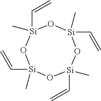


D00000

D00001

D00002

D00003

D00004

D00005

D00006

D00007

D00008

D00009

D00010

D00011

D00012

D00013

D00014

XML
uspto.report is an independent third-party trademark research tool that is not affiliated, endorsed, or sponsored by the United States Patent and Trademark Office (USPTO) or any other governmental organization. The information provided by uspto.report is based on publicly available data at the time of writing and is intended for informational purposes only.
While we strive to provide accurate and up-to-date information, we do not guarantee the accuracy, completeness, reliability, or suitability of the information displayed on this site. The use of this site is at your own risk. Any reliance you place on such information is therefore strictly at your own risk.
All official trademark data, including owner information, should be verified by visiting the official USPTO website at www.uspto.gov. This site is not intended to replace professional legal advice and should not be used as a substitute for consulting with a legal professional who is knowledgeable about trademark law.