Method And Device For Determining A Maximum Speed For A Vehicle And Automatic Drive System
Ross; Hans-Leo ; et al.
U.S. patent application number 16/485694 was filed with the patent office on 2020-01-02 for method and device for determining a maximum speed for a vehicle and automatic drive system. The applicant listed for this patent is Robert Bosch GmbH. Invention is credited to Thomas Friedrich, Hans-Leo Ross.
| Application Number | 20200001866 16/485694 |
| Document ID | / |
| Family ID | 60788588 |
| Filed Date | 2020-01-02 |


| United States Patent Application | 20200001866 |
| Kind Code | A1 |
| Ross; Hans-Leo ; et al. | January 2, 2020 |
METHOD AND DEVICE FOR DETERMINING A MAXIMUM SPEED FOR A VEHICLE AND AUTOMATIC DRIVE SYSTEM
Abstract
A method for determining a maximum speed for a vehicle, including: receiving items of state information concerning a state of at least one vehicle component of the vehicle; and determining a maximum speed of the vehicle on the basis of the state information, such that a stopping path of the vehicle from a recognition of a dangerous state until the vehicle is at a standstill is less than or equal to a specified value.
| Inventors: | Ross; Hans-Leo; (Lorsch, DE) ; Friedrich; Thomas; (Ingersheim, DE) | ||||||||||
| Applicant: |
|
||||||||||
|---|---|---|---|---|---|---|---|---|---|---|---|
| Family ID: | 60788588 | ||||||||||
| Appl. No.: | 16/485694 | ||||||||||
| Filed: | December 13, 2017 | ||||||||||
| PCT Filed: | December 13, 2017 | ||||||||||
| PCT NO: | PCT/EP2017/082618 | ||||||||||
| 371 Date: | August 13, 2019 |
| Current U.S. Class: | 1/1 |
| Current CPC Class: | B60W 2520/04 20130101; B62D 15/0285 20130101; B60W 2554/00 20200201; B60W 2520/10 20130101; B60W 30/09 20130101; B60Y 2302/05 20130101 |
| International Class: | B60W 30/09 20060101 B60W030/09; B62D 15/02 20060101 B62D015/02 |
Foreign Application Data
| Date | Code | Application Number |
|---|---|---|
| Feb 15, 2017 | DE | 10 2017 202 363.5 |
Claims
1-10. (canceled)
11. A method for determining a maximum speed for a vehicle, the method comprising: receiving items of state information concerning a state of at least one vehicle component of the vehicle; and determining a maximum speed of the vehicle based on the state information, such that a stopping path of the vehicle from a recognition of a dangerous state until the vehicle is at a standstill is less than or equal to a specified value.
12. The method of claim 11, wherein the state information includes information about a state of at least one vehicle sensor of the vehicle, and based on the information about the state of the at least one vehicle sensor, a recognition time is calculated that is required for the recognition of the dangerous state, and the maximum speed is determined taking into account the recognition time.
13. The method of claim 11, wherein the state information includes information about a state of a brake system of the vehicle, and based on the information about the state of the brake system, a braking time from a beginning of the braking process until the vehicle is at a standstill is calculated, and the maximum speed is determined taking into account the braking time.
14. The method of claim 13, wherein the calculation of the braking time includes: (i) calculating a first braking time from a beginning of the braking process until the full braking power has been reached; and (ii) calculating a second braking time from the reaching of the full braking power until the vehicle is at a standstill.
15. The method of claim 12, wherein the state information includes information about a state of a brake system of the vehicle, and based on the information about the state of the brake system, a braking time from a beginning of the braking process until the vehicle is at a standstill is calculated, and the maximum speed is determined taking into account the braking time, and wherein the state information includes information about a state of a communication system between the brake system and the at least one vehicle sensor, and based on the information about the state of the communication system, a communication time is calculated for the communication between the brake system and the at least one vehicle sensor, and the maximum speed is determined taking into account the communication time.
16. A device for determining a maximum speed for a vehicle, comprising: an input interface to receive state information concerning a state of at least one vehicle component of the vehicle; and a determining device to determine the maximum speed of the vehicle based on the state information so that a stopping path of the vehicle from a recognition of a dangerous state until the vehicle is at a standstill is less than or equal to a specified value.
17. The device of claim 16, wherein the state information includes information concerning a state of at least one vehicle sensor of the vehicle, and wherein the determining device is configured to calculate, based on the information concerning the state of the at least one vehicle sensor, a recognition time that is required to recognize the dangerous state, and to determine the maximum speed taking into account the recognition time.
18. The device of claim 16, wherein the state information includes information concerning a state of a brake system of the vehicle, and wherein the determining device is configured to calculate, based on the information concerning the state of the brake system, a braking time from a beginning of the braking process until the vehicle is at a standstill, and to determine the maximum speed taking into account the braking time.
19. The device of claim 17, wherein the state information includes information concerning a state of a communication system between the brake system and the at least one vehicle sensor, and wherein the determining device is configured to calculate, based on the information concerning the state of the communication system, a communication time for the communication between the brake system and the at least one vehicle sensor, and to determine the maximum speed taking into account the communication time.
20. An automated driving system for a vehicle, comprising: a device for determining a maximum speed for a vehicle, including: an input interface to receive state information concerning a state of at least one vehicle component of the vehicle; and a determining device to determine the maximum speed of the vehicle based on the state information so that a stopping path of the vehicle from a recognition of a dangerous state until the vehicle is at a standstill is less than or equal to a specified value; and at least one vehicle component that is coupled to the device and is configured to transmit state information to the device.
Description
FIELD OF THE INVENTION
[0001] The present invention relates to a method for determining a maximum speed for vehicle, to a device for determining a maximum speed for vehicle, and to an automated driving system for a vehicle.
BACKGROUND INFORMATION
[0002] The braking power of emergency brake assistance systems for vehicles may be reduced for various reasons. For example, the time required to recognize dangerous situations may become longer due to poor weather conditions. In addition, the communication between the components required for emergency braking may become impaired due to a defect, thus increasing the communication time. Finally, deterioration of hydraulic elements of the brake system is also possible, lengthening the brake path.
[0003] From DE 10 2013 213 169 A1, it is believed to be understood, after recognizing a defect in components of a vehicle, to put the vehicle into an emergency operating mode and to bring it to a standstill.
SUMMARY OF THE INVENTION
[0004] The present invention provides a method for determining a maximum speed for a vehicle having the features described herein, a device for determining a maximum speed for a vehicle having the features described herein, and an automated driving system for a vehicle.
[0005] According to a first aspect, the present invention relates to a method for determining a maximum speed for a vehicle. Here, items of state information about a state of at least one vehicle component of the vehicle are received. A maximum speed of the vehicle is determined or calculated, on the basis of the state information, in such a way that a stopping path of the vehicle from a recognition of a dangerous state until the vehicle is at a standstill is less than or equal to a specified value.
[0006] According to another aspect, the present invention relates to a device for determining a maximum speed for a vehicle, having an input interface and a determining device. The input interface is configured to receive state information relating to a state of at least one vehicle component of the vehicle. The determining device is configured to determine the maximum speed of the vehicle on the basis of the state information in such a way that a stopping path of the vehicle from a recognition of a dangerous state until the vehicle is at a standstill is less than or equal to a specified value.
[0007] According to another aspect, the present invention relates to an automated driving system for a vehicle, having a device for determining a maximum speed for the vehicle and having at least one vehicle component that is coupled to the device and is configured to transmit state information to the device.
[0008] Specific embodiments are the subject matter of the respective further descriptions herein.
[0009] Vehicle components of the vehicle may be understood as devices of the vehicle that are required for the braking of the vehicle, for example via an automated emergency braking assistant.
[0010] The state information concerning the state of the vehicle components may include items of information about a possible impairment of the vehicle components. The state information can also include items of information about a period of time that the corresponding vehicle component requires for its respective contribution to the braking of the vehicle.
[0011] If the state of one or more vehicle components is impaired, then in general the stopping path of the vehicle at a specified vehicle speed will become longer. As a result, in specific cases a safe braking of the vehicle may no longer be guaranteed. According to the present invention, therefore, the maximum speed of the vehicle is determined in such a way that the stopping path does not exceed a specified threshold value. In this way, safe braking, and thus prevention of accidents, are possible at all times.
[0012] At the same time, the maximum speed may be chosen to be as high as possible, without the stopping path exceeding the specified value. This makes it possible for the driver, or an automatic driving system, to convey the vehicle to a safe parking position or to a repair shop without presenting an obstacle for other traffic participants.
[0013] The state information may include information about a state of at least one vehicle sensor of the vehicle, such that on the basis of the information about the state of the at least one vehicle sensor, a recognition time is calculated that is required for recognizing the dangerous state. The maximum speed is determined taking into account the recognition time. The vehicle sensors can for example include radar sensors, infrared sensors, or vehicle cameras that monitor a surrounding environment of the vehicle and are configured to recognize objects in the surrounding environment of the vehicle. The information about the state can include information about a degree of precision of recognition of the at least one vehicle sensor, ascertained for example on the basis of weather conditions around the vehicle.
[0014] According to a development, the items of state information include information about a state of a brake system of the vehicle, a braking time from the beginning of the braking process until the vehicle is at a standstill being calculated on the basis of the information about the state of the brake system, and the maximum speed being determined taking into account the braking time.
[0015] The calculation of the braking time can include the calculation of a first braking time from a beginning of the braking process until the full braking power has been reached, and the calculation of a second braking time from the reaching of the full braking power until the vehicle is at a standstill. The brake system can for example include an antilocking system. The brake system can also include a hydraulic system. The first braking time corresponds to the time required to build up the brake pressure of the hydraulic system. The delay of the vehicle during the pressure buildup phase is in general not constant, whereas during the second braking time the deceleration is essentially constant.
[0016] According to a development of the method, the state information can include information about a state of the communication system between the brake system and the at least one vehicle sensor. On the basis of the information about the state of the communication system, a communication time for the communication between the brake system and the at least one vehicle sensor is calculated, and the maximum speed is determined taking into account the communication time. The method according to the present invention thus takes into account possible time losses due to a suboptimal communication between the components required for the emergency braking.
[0017] According to a further development of the device, the state information includes information about the state of at least one vehicle sensor of the vehicle, the determining device being configured to calculate, on the basis of the information about the state of the at least one vehicle sensor, a recognition time required for the recognition of the dangerous state. The determining device is in addition configured to determine the maximum speed taking into account the recognition time.
[0018] According to a development of the device, the state information includes information about a state of a brake system of the vehicle, the determining device being configured to calculate, on the basis of the information about the state of the brake system, a braking time from a beginning of the braking process until the vehicle is at a standstill, and to determine the maximum speed taking into account the braking time.
[0019] According to a development of the device, in order to calculate the braking time the determining device is configured to calculate a first braking time from a beginning of the braking process until the full braking power is achieved, and a second braking time from the reaching of the full braking power until the vehicle is at a standstill.
[0020] According to a development of the device, the items of state information include information about a state of a communication system between the braking system and the at least one vehicle sensor, the determining device being configured to calculate, on the basis of the information about the state of the communication system, a communication time for the communication between the brake system and the at least one vehicle sensor, and to determine the maximum speed taking into account the communication time.
[0021] In all the Figures, identical or functionally identical elements and devices have been provided with the same reference characters. Specific embodiments can be combined with one another in any manner deemed appropriate.
BRIEF DESCRIPTION OF THE DRAWINGS
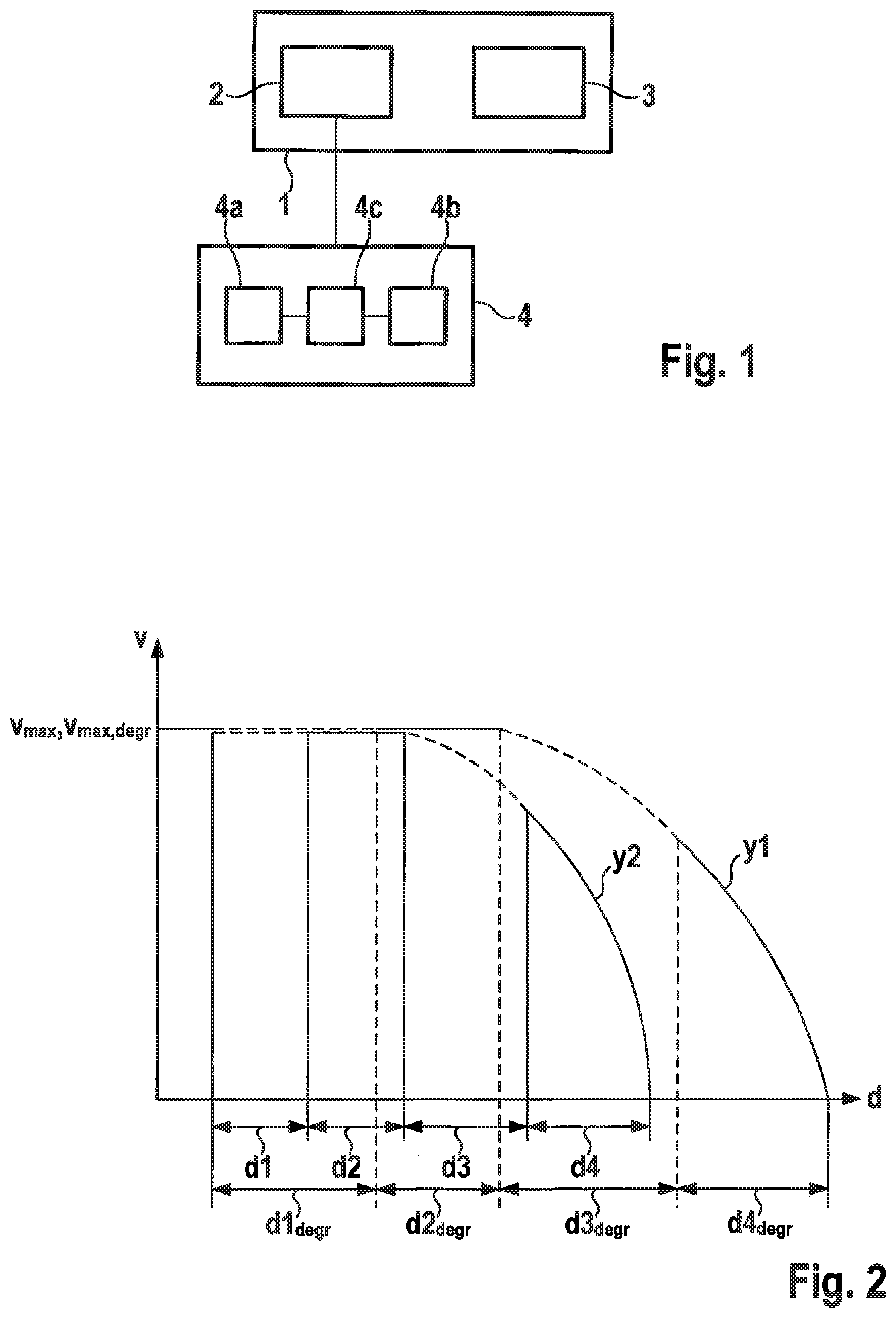
[0022] FIG. 1 shows a schematic diagram of a device for determining a maximum speed for a vehicle according to a specific embodiment of the present invention.
[0023] FIG. 2 shows an illustration of a stopping path of a vehicle under normal conditions and under impaired conditions, with the same initial speed in each case.
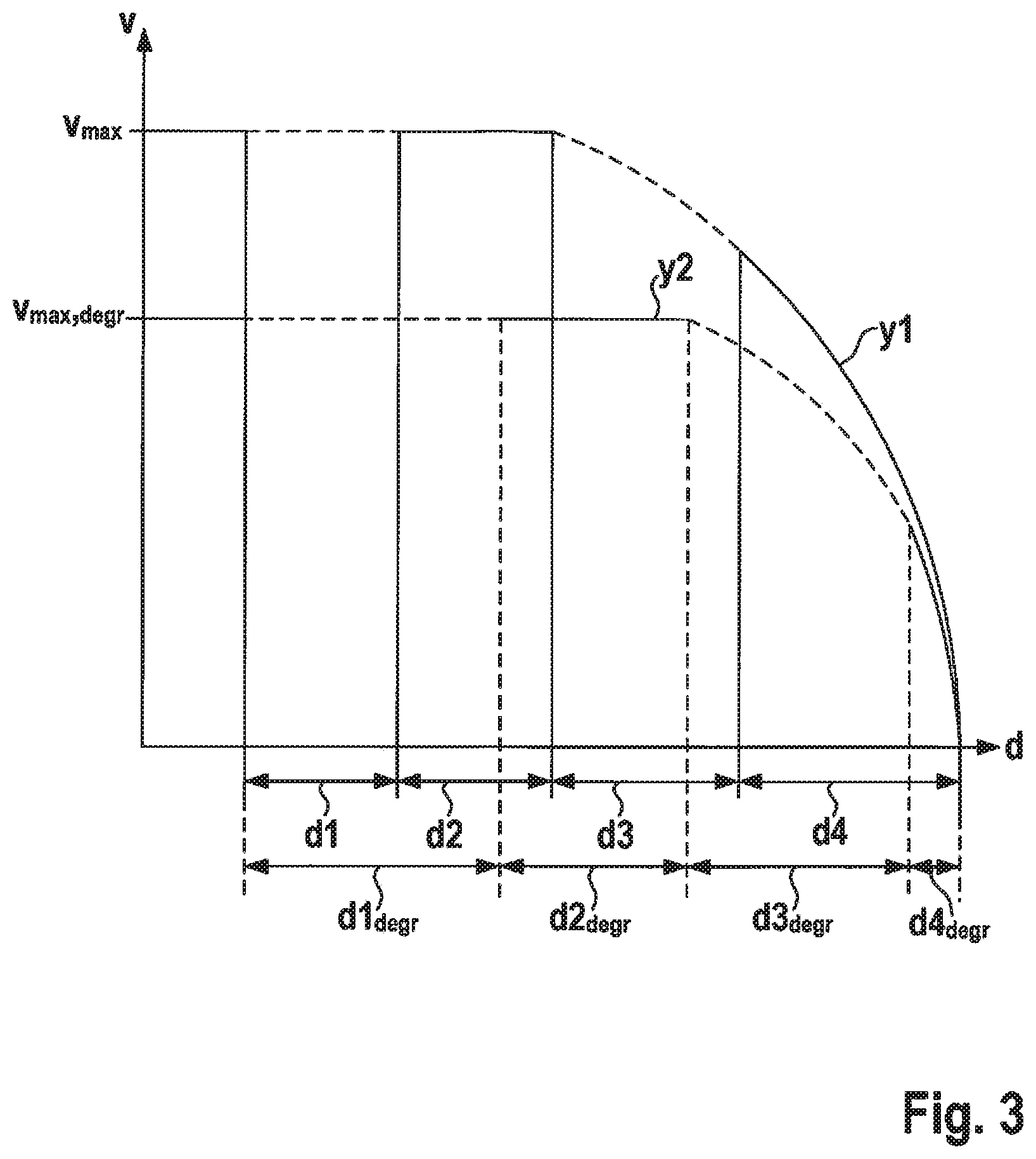
[0024] FIG. 3 shows an illustration of the stopping path under normal conditions and under impaired conditions and with reduced initial speed.
[0025] FIG. 4 shows a schematic diagram of an automated driving system for a vehicle according to a specific embodiment of the present invention.
[0026] FIG. 5 shows a flow diagram explaining a method for determining a maximum speed for a vehicle according to a specific embodiment of the present invention.
DETAILED DESCRIPTION
[0027] FIG. 1 shows a block diagram of a device 1 for determining a maximum speed for a vehicle.
[0028] Device 1 includes an input interface 2 that is configured to receive state information concerning a state of vehicle components 4. Input interface 2 can be coupled to the vehicle components 4 for this purpose. In particular, input interface 2 can be capable of being coupled to vehicle components 4 via a bus system of the vehicle.
[0029] Device 1 further includes a determining device 3 that is configured to determine, on the basis of the state information, the maximum speed v.sub.max of the vehicle in such a way that a stopping path d.sub.stopping of the vehicle from a recognition of a dangerous state until the vehicle is at a standstill is less than or equal to a specified value.
[0030] Vehicle components 4 include at least one vehicle sensor 4a that can include radar sensors, infrared sensors, or vehicle cameras. Vehicle sensor 4a is configured to provide sensor data or environmental data relating to a surrounding environment of the vehicle. Vehicle sensor 4a may include a recognition device that is configured to recognize a dangerous situation on the basis of the sensor data.
[0031] Vehicle components 4 further include a brake system 4b that is configured to brake the vehicle. Brake system 4b may include a hydraulic brake system, for example a plunger-based brake system or a piston brake system. The brake system can in addition include an anti-locking system. The brake system can include an automatic brake system that automatically brakes the vehicle to a standstill when a dangerous state has been recognized by the at least one vehicle sensor 4a.
[0032] Vehicle components 4 further include a communication system 4c that is coupled to brake system 4b and to the at least one vehicle sensor 4a and that is configured to transmit information from the at least one vehicle sensor 4a, possibly via at least one control device, to brake system 4b. Communication system 4c can include a bus system of the vehicle.***
[0033] Vehicle components 4a, 4b, 4c can each provide corresponding information about the state of the respective vehicle component 4a, 4b, 4c, and transmit it to input interface 2.
[0034] This state information can include for example information about a state of the at least one vehicle sensor 4a. This can include for example a recognition time TD ("time to detect") that the at least one vehicle sensor 4a requires in order to acquire an object, such as a pedestrian, to classify it, and to recognize a dangerous state. Recognition time TD thus corresponds to the time required for vehicle sensor 4a to recognize the dangerous state. If at least one of the vehicle sensors 4a fails due to a defect or has a lower precision of recognition due to changed environmental conditions, such as poor weather conditions, then recognition time TD is reduced correspondingly. The information about the state of the at least one vehicle sensor 4a can include the recognition time TD reduced in this way. The information about the state of the at least one vehicle sensor 4a can however also include information relating to a defect or to the operating states of vehicle sensor 4a, determining device 3 being configured to calculate recognition time TD on the basis of this information.
[0035] The state information can in addition include information about a state of brake system 4b, for example information as to whether brake system 4b is in a normal state or in an impaired state. Determining device 3 is configured to calculate, based on the information about the state of brake system 4b, a brake time TB ("time to brake") from a beginning of the braking process until the vehicle is at a standstill. Determining device 3 here calculates a first brake time TTL ("time to lock") from a beginning of the braking process until the full braking power is achieved. In a hydraulic brake system, this corresponds to the time required to build up the complete brake pressure. In addition, determining device 3 calculates a second brake time T.sub.stop from the reaching of the full brake power until the vehicle is at a standstill. This corresponds to the time required by the brake system to brake the vehicle at full brake pressure.
[0036] Braking time TB corresponds to the sum of first braking time TTL and second braking time T.sub.stop.
[0037] In addition, the items of state information include information about a state of communication system 4c, determining device 3 being configured to calculate, on the basis of the information about the state of the communication system 4c, a communication time TT ("time to travel") for the communication between brake system 4b and the at least one vehicle sensor 4a.
[0038] The respective items of state information can be ascertained by the respective vehicle components 4 themselves, using recognition algorithms. However, the items of state information can also be ascertained by a sensor device of device 1.
[0039] According to further specific embodiments, the items of state information can already include recognition time TD, brake time TB, and/or communication time TT.
[0040] Determining device 3 is configured to calculate a maximum stopping path d.sub.stopping of the vehicle, which is initially moving at a maximum speed v.sub.max, on the basis of the following equation:
d.sub.stopping=d1+d2+d3+d4,
where d1=TDv.sub.max, d2=TTv.sub.max, d3=TTLv.sub.max-1/6kTTL.sup.3, and d4=v.sub.rest.sup.2/(2a.sub.max).
[0041] The first stopping path segment d1 corresponds to the path traveled during recognition time TD, the second stopping path segment d2 corresponds to the path traveled during communication time TT, the third stopping path segment d3 corresponds to the path traveled during the first braking time TTL, and the fourth stopping path segment d4 corresponds to the path traveled during the second braking time T.sub.stop.
[0042] The variable a.sub.TTL=kTTL is the delay during the pressure buildup phase, where k=a.sub.max/TTL is the linear increase. Here, a.sub.max is the maximum deceleration that brake system 4b exerts on the vehicle during second braking time T.sub.stop. The first integral of a.sub.TTL is v.sub.TTL=1/2kTTL.sup.2 and the second integral is d.sub.TTL=1/6kTTL.sup.3, which is the second term of third stopping path segment d3.
[0043] While, here, a linear curve is assumed for the deceleration, determining device 3 can also take into account, as a function of the characteristic of brake system 4b, a non-linear functional dependence of the deceleration on the first braking time TTL; in this case the respective shapes would be correspondingly modified.
[0044] In addition, v.sub.rest=v.sub.max-1/2kTTL.sup.2 is the residual speed after the complete buildup of brake pressure, i.e. after first braking time TTL. Substituting this relation into the equation for the stopping path d.sub.stopping yields the following equation:
d.sub.stopping=TDv.sub.max+TTv.sub.max-TTLv.sub.max-1/6kTTL.sup.3+(v.sub- .max-1/2kTTL.sup.2).sup.2/(2a.sub.max)
[0045] In an errored or degraded state, first braking time TTL, second braking time T.sub.stop, recognition time TD and communication time TT, as well as the maximum deceleration a.sub.max, can deviate from the corresponding values in the normal state. In the degraded state, determining device 3 calculates stopping path d.sub.stopping according to the following equation, in which the maximum speed v.sub.max,degr is a free parameter:
d.sub.stopping degr,degr=TD.sub.degrv.sub.max,degr+TT.sub.degrv.sub.max,degrTTL.sub.degr- v.sub.max,degr-1/6kTTL.sub.degr.sup.3+(v.sub.max,degr-1/2kTTL.sub.degr.sup- .2).sup.2/(2a.sub.max,degr).
[0046] Here, the index "degr" stands for the value of the respective variable in the degraded state.
[0047] If the maximum speed v.sub.max of the vehicle is not changed, i.e. if v.sub.max=v.sub.max,degr, then the scenario shown in FIG. 2 results. In the normal state, the course of speed v shown in curve y1 results as a function of the traveled distance d. Due to the stopping path segments, prolonged in the degraded state, d1.sub.degr, d2.sub.degr, d3.sub.degr, d4.sub.degr, the overall stopping path becomes longer, as can be seen in the course of speed v shown in curve y2.
[0048] Determining device 3 is configured to calculate the maximum speed v.sub.max in such a way that the stopping path d.sub.stopping,degr in the degraded state, starting from the maximum speed v.sub.max,degr in the degraded state, is the same size as the stopping path d.sub.stopping in the normal state, starting from the maximum speed v.sub.max in the normal state. This corresponds to the scenario illustrated in FIG. 3.
[0049] Thus, determining device 3 calculates the maximum speed v.sub.max under the condition d.sub.stopping=d.sub.stopping,degr. Substitution and rewriting first yields the following equation:
d.sub.stopping+1/6kTTL.sub.degr.sup.3=TD.sub.degrv.sub.max,degr+TT.sub.d- egrb.sub.max,degr+TTL.sub.degrv.sub.max,degr+v.sub.max,degr.sup.2/(2a.sub.- max,degr)-v.sub.max,degrkTTL.sub.degr.sup.2/2a.sub.max,degr+1/4k.sup.2TTL.- sub.degr.sup.4/(2a.sub.max,degr)
and, finally, the following equation:
d.sub.stopping+1/6kTTL.sub.degr.sup.3-1/4k.sup.2TTL.sub.degr.sup.4/(2a.s- ub.max,degr)=v.sub.max,degr(TD.sub.degr+TT.sub.degr+TTL.sub.degr-kTTL.sub.- degr.sup.2/(2a.sub.max,degr))+v.sub.max,degr.sup.2/(2a.sub.max,degr).
[0050] The latter expression is a second-order equation for v.sub.max,degr that is correspondingly solved by determining device 3 according to v.sub.max,degr. The value obtained by solving this equation is the maximum speed calculated by determining device 3.
[0051] According to a development, device 1 can be configured to control brake system 4b in such a way that the first brake time TTL is reduced when determining device 3 recognizes, on the basis of the state information, the impairment of at least one vehicle component 4. Thus, device 1 can control brake system 4b using a control signal in such a way that a hydraulic brake apparatus of brake system 4b is pre-filled with a pressure at a specified level, for example 5 bar. In this way, the time required to reach full braking power is reduced.
[0052] Device 1 can in addition be configured to output a control signal in order to control the vehicle in such a way that a maximum achievable speed of the vehicle is limited by the determined maximum speed v.sub.max.
[0053] In addition, device 1 can include a display device that displays the determined maximum speed to the driver of the vehicle.
[0054] Device 1 can be an element of a driver assistance system for a vehicle that is configured to control the vehicle in such a way that the absolute speed of the vehicle is always less than the maximum speed v.sub.max.
[0055] FIG. 4 shows an automated driving system 5 for a vehicle F according to a specific embodiment of the present invention. Automated driving system 5 includes a device 1 for determining a maximum speed v.sub.max for vehicle F according to one of the above-described specific embodiments. Automatic driving system 5 also has at least one vehicle component 4 that is coupled to device 1 and is configured to transmit state information to device 1. Vehicle component 4 may include, as described above, at least one vehicle sensor 4a, a brake system 4b, and a communication system 4c between brake system 4b and the at least one vehicle sensor 4a.
[0056] Device 1 further includes a determining device 3 that, as described above, is configured to determine the maximum speed v.sub.max of the vehicle.
[0057] Automated driving system 5 may have a control device that is configured to autonomously control vehicle F, a driving speed of vehicle F always being less than the defined maximum speed v.sub.max.
[0058] FIG. 5 shows a flow diagram explaining a method for determining a maximum speed for a vehicle F.
[0059] In a first method step S1, state information is received concerning a state of at least one vehicle component 4 of vehicle F.
[0060] In a further method step S2, a maximum speed v.sub.max of vehicle F is determined on the basis of the state information, a stopping path of vehicle F from a recognition of a dangerous state until vehicle F is at a standstill always being less than or equal to a specified value. The calculation of the maximum speed v.sub.max can be carried out according to one of the specific embodiments described above.
* * * * *
D00000
D00001
D00002
D00003
XML
uspto.report is an independent third-party trademark research tool that is not affiliated, endorsed, or sponsored by the United States Patent and Trademark Office (USPTO) or any other governmental organization. The information provided by uspto.report is based on publicly available data at the time of writing and is intended for informational purposes only.
While we strive to provide accurate and up-to-date information, we do not guarantee the accuracy, completeness, reliability, or suitability of the information displayed on this site. The use of this site is at your own risk. Any reliance you place on such information is therefore strictly at your own risk.
All official trademark data, including owner information, should be verified by visiting the official USPTO website at www.uspto.gov. This site is not intended to replace professional legal advice and should not be used as a substitute for consulting with a legal professional who is knowledgeable about trademark law.