Implantable Medical Device With Gyroscope
Mi; Bin ; et al.
U.S. patent application number 16/535890 was filed with the patent office on 2020-01-02 for implantable medical device with gyroscope. This patent application is currently assigned to CARDIAC PACEMAKERS, INC.. The applicant listed for this patent is CARDIAC PACEMAKERS, INC.. Invention is credited to Qi An, Viktoria A. Averina, Michael J. Kane, Brendan Early Koop, Keith R. Maile, Bin Mi, Krzysztof Z. Siejko, Jeffrey E. Stahmann, Pramodsingh Hirasingh Thakur, Yinghong Yu.
| Application Number | 20200001092 16/535890 |
| Document ID | / |
| Family ID | 62020400 |
| Filed Date | 2020-01-02 |


View All Diagrams
| United States Patent Application | 20200001092 |
| Kind Code | A1 |
| Mi; Bin ; et al. | January 2, 2020 |
IMPLANTABLE MEDICAL DEVICE WITH GYROSCOPE
Abstract
An implantable medical device (IMD) that includes a housing, a first electrode secured relative to the housing, a second electrode secured relative to the housing, and a gyroscope secured relative to the housing. The IMD may include circuitry in the housing in communication with the first electrode, the second electrode, and the gyroscope. The circuitry may be configured to determine and store a plurality of torsion data measurements, from which a representation of a twist profile may be determined.
| Inventors: | Mi; Bin; (Plymouth, MN) ; Thakur; Pramodsingh Hirasingh; (Woodbury, MN) ; Stahmann; Jeffrey E.; (Ramsey, MN) ; Maile; Keith R.; (New Brighton, MN) ; An; Qi; (Blaine, MN) ; Koop; Brendan Early; (Ham Lake, MN) ; Yu; Yinghong; (Shoreview, MN) ; Averina; Viktoria A.; (Shoreview, MN) ; Kane; Michael J.; (St. Paul, MN) ; Siejko; Krzysztof Z.; (Maple Grove, MN) | ||||||||||
| Applicant: |
|
||||||||||
|---|---|---|---|---|---|---|---|---|---|---|---|
| Assignee: | CARDIAC PACEMAKERS, INC. St. Paul MN |
||||||||||
| Family ID: | 62020400 | ||||||||||
| Appl. No.: | 16/535890 | ||||||||||
| Filed: | August 8, 2019 |
Related U.S. Patent Documents
| Application Number | Filing Date | Patent Number | ||
|---|---|---|---|---|
| 15791286 | Oct 23, 2017 | 10413733 | ||
| 16535890 | ||||
| 62413787 | Oct 27, 2016 | |||
| Current U.S. Class: | 1/1 |
| Current CPC Class: | A61B 5/1121 20130101; A61B 5/02028 20130101; A61B 5/0472 20130101; A61B 2562/0219 20130101; A61B 5/0205 20130101; A61N 1/3756 20130101; G01C 19/38 20130101; A61B 5/042 20130101; A61B 5/0215 20130101; A61B 5/4839 20130101; G06F 3/0346 20130101; A61N 1/37252 20130101; A61B 5/00 20130101; A61N 1/36578 20130101 |
| International Class: | A61N 1/365 20060101 A61N001/365; A61B 5/00 20060101 A61B005/00; A61B 5/02 20060101 A61B005/02; A61B 5/11 20060101 A61B005/11; A61N 1/375 20060101 A61N001/375; G01C 19/38 20060101 G01C019/38; G06F 3/0346 20060101 G06F003/0346 |
Claims
1. A leadless cardiac pacemaker (LCP) configured to sense cardiac activity and to pace a patient's heart, the LCP comprising: a housing; an electrode secured relative to the housing and exposed to an environment outside of the housing; a gyroscope disposed relative to the housing; circuitry in the housing in communication with the electrode and the gyroscope, the circuitry configured to: pace the patient's heart using the electrode; determine a twisting profile of the patient's heart over one or more cardiac cycles based at least in part on data obtained from the gyroscope; determine a status of an acute and/or chronic condition of the patient's heart based at least in part on the determined twisting profile; and communicate the status of the acute and/or chronic condition of the patient's heart to an external device.
2. The LCP of claim 1, wherein the acute and/or chronic condition of the patient's heart comprises a systolic and/or diastolic heart failure condition.
3. The LCP of claim 1, wherein the acute and/or chronic condition of the patient's heart comprises an aortic stenosis condition.
4. The LCP of claim 1, wherein the acute and/or chronic condition of the patient's heart comprises a mitral regurgitation condition.
5. The LCP of claim 1, wherein the acute and/or chronic condition of the patient's heart comprises a transmural infarction condition.
6. The LCP of claim 1, wherein the acute and/or chronic condition of the patient's heart comprises a subendocardial ischemia condition.
7. The LCP of claim 1, wherein the acute and/or chronic condition of the patient's heart comprises a cardiomyopathy condition.
8. The LCP of claim 1, wherein the acute and/or chronic condition of the patient's heart comprises a constrictive pericarditis condition.
9. The LCP of claim 1, wherein the acute and/or chronic condition of the patient's heart comprises an ejection fraction condition.
10. The LCP of claim 1, wherein the twisting profile includes one or more of a degree of twist, a twist velocity, a twist vector, and a twist angle.
11. The LCP of claim 1, wherein the status of the acute and/or chronic condition of the patient's heart is determined based at least in part on the determined twisting profile and one or more additional parameter.
12. The LCP of claim 11, wherein the one or more additional parameter comprises one or more of a cardiovascular pressure, a heart sound, an ECG attribute, a blood flow, an impedance, a respiration, and/or one or more cardiac dimensions.
13. The LCP of claim 1, wherein the circuitry is configured to update the twisting profile at a predefined regular interval.
14. The LCP of claim 1, wherein the circuitry is configured to update the twisting profile in response to a detected change in one or more of exercise and posture.
15. A medical device system, comprising: a first implantable medical device including a gyroscope for implantation in a patient; a second medical device in communication with the first implantable medical device; the first implantable medical device and/or the second medical device configured to: determine one or more torsional parameters associated with the patient based at least in part on data obtained from the gyroscope of the first implantable medical device; determine a status of an acute and/or chronic condition of the patient based at least in part on the determined one or more torsional parameters; and report the status of the acute and/or chronic condition.
16. The medical device system of claim 15, wherein the one or more torsional parameters comprises one or more of a twist velocity, a twist vector, and a twist angle.
17. The medical device system of claim 15, wherein the first implantable medical device and/or the second medical device are further configured to update the one or more torsional parameters at a predefined regular interval and/or in response to a detected change in one or more of exercise and posture.
18. A method for monitoring cardiac dysfunction of a patient's heart using a leadless cardiac pacemaker (LCP) secured to the patient's heart, wherein the LCP includes a housing, an electrode secured relative to the housing and exposed to an environment outside of the housing, and a gyroscope, disposed relative to the housing, comprising: delivering a therapy to the patients' heart using the LCP; determining a twisting profile over one or more cardiac cycles based at least in part on data obtained from the gyroscope of the leadless cardiac pacemaker (LCP); determine a status of an acute and/or chronic condition of the patient's heart based at least in part on the determined twisting profile; and communicate the status of the acute and/or chronic condition of the patient's heart to an external device.
19. The method of claim 18, wherein the twisting profile includes at least one of a degree of twist, a twist velocity, a twist vector, and a twist angle.
20. The method of claim 18, wherein the acute and/or chronic condition of the patient's heart comprises a systolic and/or diastolic heart failure condition.
Description
CROSS REFERENCE TO RELATED APPLICATIONS
[0001] This application is a continuation of co-pending U.S. patent application Ser. No 15/791,286, filed Oct. 23, 2017, which claims the benefit of U.S. Provisional Patent Application Ser. No. 62/413,787 filed on Oct. 27, 2016, both of which are incorporated herein by reference.
TECHNICAL FIELD
[0002] The present disclosure generally relates to implantable medical devices and more particularly to implantable medical devices with a gyroscope
BACKGROUND
[0003] Implantable medical devices are commonly used to perform a variety of functions, such as to monitor one or more conditions and/or delivery therapy to a patient. In some cases, an implantable medical device may deliver neurostimulation therapy to a patient. In some cases, an implantable medical device may simply monitor one or more conditions, such as pressure, acceleration, cardiac events, and may communicate the detected conditions or events to another device, such as another implantable medical device or an external programmer.
[0004] In some cases, an implantable medical device may be configured to deliver pacing and/or defibrillation therapy to a patient. Such implantable medical devices may treat patients suffering from various heart conditions that may result in a reduced ability of the heart to deliver sufficient amounts of blood to a patient's body. In some cases, heart conditions may lead to rapid, irregular, and/or inefficient heart contractions. To help alleviate some of these conditions, various devices (e.g., pacemakers, defibrillators, etc.) may be implanted into a patient's body. When so provided, such devices can monitor and provide therapy, such as electrical stimulation therapy, to the patient's heart to help the heart operate in a more normal, efficient and/or safe manner. In some cases, a patient may have multiple implanted devices that cooperate to monitor and/or provide therapy to the patient's heart.
SUMMARY
[0005] The present disclosure generally relates to implantable medical devices and more particularly to implantable medical devices with gyroscopes.
[0006] In a first example, a leadless cardiac pacemaker (LCP) configured to sense cardiac activity and to pace a patient's heart may comprise a housing, an electrode secured relative to the housing and exposed to the environment outside of the housing, a gyroscope disposed relative to the housing, and circuitry in the housing in communication with the electrode and the gyroscope. The circuitry may be configured to generate a twisting profile over one or more cardiac cycles. The circuitry may be further configured to update one or more to pacing parameters of the LCP based at least in part on the twisting profile and pace the patient's heart using one or more of the updated pacing parameters.
[0007] Alternatively or additionally to any of the examples above, in another example, the circuitry may be configured to update the twisting profile at a predefined regular interval.
[0008] Alternatively or additionally to any of the examples above, in another example, the circuitry may be configured to update the twisting profile in response to a detected condition change.
[0009] Alternatively or additionally to any of the examples above, in another example, the detected condition change may correspond to one of exercise, heart failure status, therapy modification (e.g., medication), cardiac status, pacing status, or posture.
[0010] Alternatively or additionally to any of the examples above, in another example, updating the one or more pacing parameters of the LCP may comprise adjusting an AV delay.
[0011] Alternatively or additionally to any of the examples above, in another example, updating the one or more pacing parameters of the LCP may comprise adjusting a VV delay.
[0012] Alternatively or additionally to any of the examples above, in another example, updating the one or more pacing parameters of the LCP may comprise a selection of different pacing vector.
[0013] Alternatively or additionally to any of the examples above, in another example, the circuitry may be further configured to compare (e.g., correlate) the twisting profile to an additional parameter to determine if the twisting profile is abnormal.
[0014] Alternatively or additionally to any of the examples above, in another example, the additional parameter may be one or more of a cardiovascular (e.g., ventricular) pressure, a heart sound, an ECG attribute (e.g., QRS width), a blood flow, impedance, respiration, and/or one or more cardiac dimensions.
[0015] In another example, a medical device system may comprise a first implantable medical device including a gyroscope, the first implantable medical device configured to be secured to a patient's heart and a second medical device. The first implantable medical device and/or the second medical device may be configured to determine a twisting profile of the patient's heart based at least in part on an output of the gyroscope, adjust one or more therapy parameters of a therapy based at least in part on the twisting profile, and deliver the therapy using one or more of the adjusted therapy parameters.
[0016] Alternatively or additionally to any of the examples above, in another example, the twisting profile may comprise a twist velocity, a twist vector, a twist angle, and their temporal progression related to the cardiac cycle. The twist vector can be defined as the axis normal to the plane of the twist.
[0017] Alternatively or additionally to any of the examples above, in another example, the twisting profile may provide confirmation of an event detected by the second medical device.
[0018] Alternatively or additionally to any of the examples above, in another example, the first implantable medical device and/or the second medical device may be further configured to update the twisting profile at a predefined regular interval.
[0019] Alternatively or additionally to any of the examples above, in another example, the first implantable medical device and/or the second medical device may be further configured to update the twisting profile in response to a detected condition change.
[0020] Alternatively or additionally to any of the examples above, in another example, the detected condition change may correspond to one of exercise, heart failure status, or posture.
[0021] Alternatively or additionally to any of the examples above, in another example, the first implantable medical device and/or the second medical device may be further configured to correlate the twisting profile to an additional parameter to determine if the twisting profile is abnormal.
[0022] In another example, a method for monitoring cardiac dysfunction of a patient's heart may comprise determining one or more twisting parameters of the patient's heart based at least in part on an output of a gyroscope secured relative to the patient's heart, adjusting a therapy for the patient's heart based at least in part on the one or more twisting parameters, and delivering the adjusted therapy to the patient's heart.
[0023] Alternatively or additionally to any of the examples above, in another example, the one or more twisting parameters may include at least one of a twist angle, a twist vector and a twist velocity, all related to the timing of a cardiac cycle.
[0024] Alternatively or additionally to any of the examples above, in another example, adjusting a therapy may comprise adjusting an implant location of a therapy delivering device.
[0025] Alternatively or additionally to any of the examples above, in another example, adjusting a therapy may comprise adjusting an AV delay.
[0026] Alternatively or additionally to any of the examples above, in another example, adjusting a therapy may comprise adjusting a VV delay.
[0027] Alternatively or additionally to any of the examples above, in another example, adjusting a therapy may comprise delivering an ATP therapy when the one or more twisting parameters indicate a tachyarrhythmia that is treatable with ATP therapy.
[0028] Alternatively or additionally to any of the examples above, in another example, adjusting a therapy may comprise altering a medication either via a direct action of a person or via a worn or implanted drug delivery device.
[0029] The above summary is not intended to describe each embodiment or every implementation of the present disclosure. Advantages and attainments, together with a more complete understanding of the disclosure, will become apparent and appreciated by referring to the following description and claims taken in conjunction with the accompanying drawings.
BRIEF DESCRIPTION OF THE DRAWINGS
[0030] The disclosure may be more completely understood in consideration of the following description of various illustrative embodiments in connection with the accompanying drawings, in which:
[0031] FIG. 1 is a schematic block diagram of an illustrative leadless cardiac pacemaker (LCP) according to one example of the present disclosure;
[0032] FIG. 2 is a schematic block diagram of another medical device (MD), which may be used in conjunction with an LCP 100 (FIG. 1) in order to detect and/or treat cardiac arrhythmias and other heart conditions;
[0033] FIG. 3 is a schematic diagram of an exemplary medical system that includes multiple LCPs and/or other devices in communication with one another;
[0034] FIG. 4 is a schematic diagram of an exemplary medical system that includes an LCP and another medical device, in accordance with yet another example of the present disclosure;
[0035] FIG. 5 is a schematic diagram of an exemplary medical system that includes an LCP and another medical device, in accordance with yet another example of the present disclosure;
[0036] FIG. 6 is a side view of an illustrative implantable leadless cardiac pacing device;
[0037] FIG. 7A is a partial cross-sectional plan view of an example leadless cardiac pacing device implanted within a heart during ventricular filling;
[0038] FIG. 7B is a partial cross-sectional plan view of another example leadless cardiac pacing device implanted within a heart during ventricular filling;
[0039] FIG. 8 is a flow diagram of an illustrative method for generating a twisting profile for a ventricle of a human heart;
[0040] FIG. 9 is a diagram showing illustrative uses of torsion measurements for the ventricle; and
[0041] FIG. 10 is another diagram showing illustrative uses of torsion measurements for the ventricle.
[0042] While the disclosure is amenable to various modifications and alternative forms, specifics thereof have been shown by way of example in the drawings and will be described in detail. It should be understood, however, that the intention is not to limit aspects of the disclosure to the particular illustrative embodiments described. On the contrary, the intention is to cover all modifications, equivalents, and alternatives falling within the spirit and scope of the disclosure.
DESCRIPTION
[0043] The following description should be read with reference to the drawings in which similar elements in different drawings are numbered the same. The description and the drawings, which are not necessarily to scale, depict illustrative embodiments and are not intended to limit the scope of the disclosure. While the present disclosure is applicable to any suitable implantable medical device (IMD), the description below uses pacemakers and more particularly leadless cardiac pacemakers (LCP) as particular examples.
[0044] A normal, healthy heart induces contraction by conducting intrinsically generated electrical signals throughout the heart. These intrinsic signals cause the muscle cells or tissue of the heart to contract. This contraction forces blood out of and into the heart, providing circulation of the blood throughout the rest of the body. However, many patients suffer from cardiac conditions that affect this contractility of their hearts. For example, some hearts may develop diseased tissues that no longer generate or conduct intrinsic electrical signals. In some examples, diseased cardiac tissues conduct electrical signals at differing rates, thereby causing an unsynchronized and inefficient contraction of the heart. In other examples, a heart may initiate intrinsic signals at such a low rate that the heart rate becomes dangerously low. In still other examples, a heart may generate electrical signals at an unusually high rate. In some cases such an abnormality can develop into a fibrillation state, where the contraction of the patient's heart chambers are almost completely de-synchronized and the heart pumps very little to no blood. Implantable medical devices, which may be configured to determine occurrences of such cardiac abnormalities or arrhythmias and deliver one or more types of electrical stimulation therapy to patient's hearts, may help to terminate or alleviate these and other cardiac conditions.
[0045] FIG. 1 depicts an illustrative leadless cardiac pacemaker (LCP) that may be implanted into a patient and may operate to prevent, control, or terminate cardiac arrhythmias in patients by, for example, appropriately employing one or more therapies (e.g. anti-tachycardia pacing (ATP) therapy, cardiac resynchronization therapy (CRT), bradycardia therapy, defibrillation pulses, or the like). As can be seen in FIG. 1, the LCP 100 may be a compact device with all components housed within the LCP 100 or directly on the housing 120. In the example shown in FIG. 1, the LCP 100 may include a communication module 102, a pulse generator module 104, an electrical sensing module 106, a mechanical sensing module 108, a processing module 110, a battery 112, and electrodes 114. The LCP 100 may include more or less modules, depending on the application.
[0046] The communication module 102 may be configured to communicate with devices such as sensors, other medical devices, and/or the like, that are located externally to the LCP 100. Such devices may be located either external or internal to the patient's body. Irrespective of the location, remote devices (i.e. external to the LCP 100 but not necessarily external to the patient's body) can communicate with the LCP 100 via the communication to module 102 to accomplish one or more desired functions. For example, the LCP 100 may communicate information, such as sensed electrical signals, data, instructions, messages, etc., to an external medical device through the communication module 102. The external medical device may use the communicated signals, data, instructions and/or messages to perform various functions, such as determining occurrences of arrhythmias, delivering electrical stimulation therapy, storing received data, analyzing received data, and/or performing any other suitable function. The LCP 100 may additionally receive information such as signals, data, instructions and/or messages from the external medical device through the communication module 102, and the LCP 100 may use the received signals, data, instructions and/or messages to perform various functions, such as determining occurrences of arrhythmias, delivering electrical stimulation therapy, storing received data, analyzing received data, and/or performing any other suitable function. The communication module 102 may be configured to use one or more methods for communicating with remote devices. For example, the communication module 102 may communicate via radiofrequency (RF) signals, inductive coupling, optical signals, acoustic signals, conducted communication signals, and/or any other signals suitable for communication.
[0047] In the example shown in FIG. 1, the pulse generator module 104 may be electrically connected to the electrodes 114. In some examples, the LCP 100 may include one or more additional electrodes 114'. In such examples, the pulse generator 104 may also be electrically connected to the additional electrodes 114'. The pulse generator module 104 may be configured to generate electrical stimulation signals. For example, the pulse generator module 104 may generate electrical stimulation signals by using energy stored in a battery 112 within the LCP 100 and deliver the generated electrical stimulation signals via the electrodes 114 and/or 114'. Alternatively, or additionally, the pulse generator 104 may include one or more capacitors, and the pulse generator 104 may charge the one or more capacitors by drawing energy from the battery 112. The pulse generator 104 may then use the energy of the one or more capacitors to deliver the generated electrical stimulation signals via the electrodes 114 and/or 114'. In at least some examples, the pulse generator 104 of the LCP 100 may include switching circuitry to selectively connect one or more of the electrodes 114 and/or 114' to the pulse generator 104 in order to select which of the electrodes 114/114' (and/or other electrodes) the pulse generator 104 delivers the electrical stimulation therapy. The pulse generator module 104 may generate electrical stimulation signals with particular features or in particular sequences in order to provide one or multiple of a number of different stimulation therapies. For example, the pulse generator module 104 may be configured to generate electrical stimulation signals to provide electrical stimulation therapy to combat bradycardia, tachycardia, cardiac dyssynchrony, bradycardia arrhythmias, tachycardia arrhythmias, fibrillation arrhythmias, cardiac synchronization arrhythmias and/or to produce any other suitable electrical stimulation therapy. Some more common electrical stimulation therapies include bradycardia therapy, anti-tachycardia pacing (ATP) therapy, cardiac resynchronization therapy (CRT), and cardioversion/defibrillation therapy.
[0048] In some examples, the LCP 100 may not include a pulse generator 104 or may turn off the pulse generator 104. When so provided, the LCP 100 may be a diagnostic only device. In such examples, the LCP 100 may not deliver electrical stimulation therapy to a patient. Rather, the LCP 100 may collect data about cardiac electrical activity and/or physiological parameters of the patient and communicate such data and/or determinations to one or more other medical devices via the communication module 102.
[0049] In some examples, the LCP 100 may include an electrical sensing module 106, and in some cases, a mechanical sensing module 108. The electrical sensing module 106 may be configured to sense the cardiac electrical activity of the heart. For example, the electrical sensing module 106 may be connected to the electrodes 114/114', and the electrical sensing module 106 may be configured to receive cardiac electrical signals conducted through the electrodes 114/114'. The cardiac electrical signals may represent local information from the chamber in which the LCP 100 is implanted. For instance, if the LCP 100 is implanted within a ventricle of the heart, cardiac electrical signals sensed by the LCP 100 through the electrodes 114/114' may represent ventricular cardiac electrical signals. The mechanical sensing module 108 may include one or more sensors, such as an accelerometer, a gyroscope, a blood pressure sensor, a heart sound sensor, a blood-oxygen sensor, a temperature sensor, a flow sensor and/or any other suitable sensors that are configured to measure one or more mechanical and/or chemical parameters of the patient. Both the electrical sensing module 106 and the mechanical sensing module 108 may be connected to a processing module 110, which may provide signals representative of the sensed mechanical parameters. Although described with respect to FIG. 1 as separate sensing modules, in some cases, the electrical sensing module 106 and the mechanical sensing module 108 may be combined into a single sensing module, as desired.
[0050] The electrodes 114/114' can be secured relative to the housing 120 but exposed to the tissue and/or blood surrounding the LCP 100. In some cases, the electrodes 114 may be generally disposed on either end of the LCP 100 and may be in electrical communication with one or more of the modules 102, 104, 106, 108, and 110. The electrodes 114/114' may be supported by the housing 120, although in some examples, the electrodes 114/114' may be connected to the housing 120 through short connecting wires such that the electrodes 114/114' are not directly secured relative to the housing 120. In examples where the LCP 100 includes one or more electrodes 114', the electrodes 114' may in some cases be disposed on the sides of the LCP 100, which may increase the number of electrodes by which the LCP 100 may sense cardiac electrical activity, deliver electrical stimulation and/or communicate with an external medical device. The electrodes 114/114' can be made up of one or more biocompatible conductive materials such as various metals or alloys that are known to be safe for implantation within a human body. In some instances, the electrodes 114/114' connected to LCP 100 may have an insulative portion that electrically isolates the electrodes 114/114' from adjacent electrodes, the housing 120, and/or other parts of the LCP 100.
[0051] The processing module 110 can be configured to control the operation of the LCP 100. For example, the processing module 110 may be configured to receive electrical signals from the electrical sensing module 106 and/or the mechanical sensing module 108. Based on the received signals, the processing module 110 may determine, for example, occurrences and, in some cases, types of arrhythmias. Based on any determined arrhythmias, the processing module 110 may control the pulse generator module 104 to generate electrical stimulation in accordance with one or more therapies to treat the determined arrhythmia(s). The processing module 110 may further receive information from the communication module 102. In some examples, the processing module 110 may use such received information to help determine whether an arrhythmia is occurring, determine a type of arrhythmia, and/or to take particular action in response to the information. The processing module 110 may additionally control the communication module 102 to send/receive information to/from other devices.
[0052] In some examples, the processing module 110 may include a pre-programmed chip, such as a very-large-scale integration (VLSI) chip and/or an application specific integrated circuit (ASIC). In such embodiments, the chip may be pre-programmed with control logic in order to control the operation of the LCP 100. By using a pre-programmed chip, the processing module 110 may use less power than other programmable circuits (e.g. general purpose programmable microprocessors) while still being able to maintain basic functionality, thereby potentially increasing the battery life of the LCP 100. In other examples, the processing module 110 may include a programmable microprocessor. Such a programmable microprocessor may allow a user to modify the control logic of the LCP 100 even after implantation, thereby allowing for greater flexibility of the LCP 100 than when using a pre-programmed ASIC. In some examples, the processing module 110 may further include a memory, and the processing module 110 may store information on and read information from the memory. In other examples, the LCP 100 may include a separate memory (not shown) that is in communication with the processing module 110, such that the processing module 110 may read and write information to and from the separate memory.
[0053] The battery 112 may provide power to the LCP 100 for its operations. In some examples, the battery 112 may be a non-rechargeable lithium-based battery. In other examples, a non-rechargeable battery may be made from other suitable materials, as desired. Because the LCP 100 is an implantable device, access to the LCP 100 may be limited after implantation. Accordingly, it is desirable to have sufficient battery capacity to deliver therapy over a period of treatment such as days, weeks, months, years or even decades. In some instances, the battery 112 may a rechargeable battery, which may help increase the useable lifespan of the LCP 100. In still other examples, the battery 112 may be some other type of power source (e.g., energy harvest from the body), as desired.
[0054] To implant the LCP 100 inside a patient's body, an operator (e.g., a physician, clinician, etc.), may fix the LCP 100 to the cardiac tissue of the patient's heart. To facilitate fixation, the LCP 100 may include one or more anchors 116. The anchor 116 may include any one of a number of fixation or anchoring mechanisms. For example, the anchor 116 may include one or more pins, staples, threads, screws, helix, tines, and/or the like. In some examples, although not shown, the anchor 116 may include threads on its external surface that may run along at least a partial length of the anchor 116. The threads may provide friction between the cardiac tissue and the anchor to help fix the anchor 116 within the cardiac tissue. In other examples, the anchor 116 may include other structures such as barbs, spikes, or the like to facilitate engagement with the surrounding cardiac tissue.
[0055] FIG. 2 depicts an example of another medical device (MD) 200, which may be used in conjunction with an LCP 100 (FIG. 1) in order to detect and/or treat cardiac arrhythmias and other heart conditions. In the example shown, the MD 200 may include a communication module 202, a pulse generator module 204, an electrical sensing module 206, a mechanical sensing module 208, a processing module 210, and a battery 218. Each of these modules may be similar to the modules 102, 104, 106, 108, and 110 of the LCP 100. Additionally, the battery 218 may be similar to the battery 112 of the LCP 100. In some examples, the MD 200 may have a larger volume within the housing 220 than LCP 100. In such examples, the MD 200 may include a larger battery and/or a larger processing module 210 capable of handling more complex operations than the processing module 110 of the LCP 100.
[0056] While it is contemplated that the MD 200 may be another leadless device such as shown in FIG. 1, in some instances the MD 200 may include leads such as leads 212. The leads 212 may include electrical wires that conduct electrical signals between the electrodes 214 and one or more modules located within the housing 220. In some cases, the leads 212 may be connected to and extend away from the housing 220 of the MD 200. In some examples, the leads 212 are implanted on, within, or adjacent to a heart of a patient. The leads 212 may contain one or more electrodes 214 positioned at various locations on the leads 212, and in some cases at various distances from the housing 220. Some of the leads 212 may only include a single electrode 214, while other leads 212 may include multiple electrodes 214. Generally, the electrodes 214 are positioned on the leads 212 such that when the leads 212 are implanted within the patient, one or more of the electrodes 214 are positioned to perform a desired function. In some cases, the one or more of the electrodes 214 may be in contact with the patient's cardiac tissue. In some cases, the one or more of the electrodes 214 may be positioned substernally or subcutaneously but adjacent the patient's heart. In some cases, the electrodes 214 may conduct intrinsically generated electrical signals to the leads 212, e.g. signals representative of intrinsic cardiac electrical activity. The leads 212 may, in turn, conduct the received electrical signals to one or more of the modules 202, 204, 206, and 208 of the MD 200. In some cases, the MD 200 may generate electrical stimulation signals, and the leads 212 may conduct the generated electrical stimulation signals to the electrodes 214. The electrodes 214 may then conduct the electrical signals and delivery the signals to the patient's heart (either directly or indirectly).
[0057] The mechanical sensing module 208, as with the mechanical sensing module 108, may contain or be electrically connected to one or more sensors, such as accelerometers, blood pressure sensors, heart sound sensors, blood-oxygen sensors, acoustic sensors, ultrasonic sensors and/or other sensors which are configured to measure one or more mechanical/chemical parameters of the heart and/or patient. In some examples, one or more of the sensors may be located on the leads 212, but this is not required. In some examples, one or more of the sensors may be located in the housing 220.
[0058] While not required, in some examples, the MD 200 may be an implantable medical device. In such examples, the housing 220 of the MD 200 may be implanted in, for example, a transthoracic region of the patient. The housing 220 may generally include any of a number of known materials that are safe for implantation in a human body and may, when implanted, hermetically seal the various components of the MD 200 from fluids and tissues of the patient's body.
[0059] In some cases, the MD 200 may be an implantable cardiac pacemaker (ICP). In this example, the MD 200 may have one or more leads, for example leads 212, which are implanted on or within the patient's heart. The one or more leads 212 may include one or more electrodes 214 that are in contact with cardiac tissue and/or blood of the patient's heart. The MD 200 may be configured to sense intrinsically generated cardiac electrical signals and determine, for example, one or more cardiac arrhythmias based on analysis of the sensed signals. The MD 200 may be configured to deliver CRT, ATP therapy, bradycardia therapy, and/or other therapy types via the leads 212 implanted within the heart or in concert with the LCP by commanding the LCP to pace. In some examples, the MD 200 may additionally be configured provide defibrillation therapy.
[0060] In some instances, the MD 200 may be an implantable cardioverter-defibrillator (ICD). In such examples, the MD 200 may include one or more leads implanted within a patient's heart. The MD 200 may also be configured to sense cardiac electrical signals, determine occurrences of tachyarrhythmias based on the sensed signals, and may be configured to deliver defibrillation therapy in response to determining an occurrence of a tachyarrhythmia. In some instances, the MD 200 may be a subcutaneous implantable cardioverter-defibrillator (S-ICD). In examples where the MD 200 is an S-ICD, one of the leads 212 may be a subcutaneously implanted lead. In at least some examples where the MD 200 is an S-ICD, the MD 200 may include only a single lead which is implanted subcutaneously, but this is not required. In some cases, the S-ICD lead may extend subcutaneously from the S-ICD can, around the sternum and may terminate adjacent the interior surface of the sternum.
[0061] In some examples, the MD 200 may not be an implantable medical device. Rather, the MD 200 may be a device external to the patient's body, and may include skin-electrodes that are placed on a patient's body. In such examples, the MD 200 may be able to sense surface electrical signals (e.g. cardiac electrical signals that are generated by the heart or electrical signals generated by a device implanted within a patient's body and conducted through the body to the skin). In such examples, the MD 200 may be configured to deliver various types of electrical stimulation therapy, including, for example, defibrillation therapy. The MD 200 may be further configured to deliver electrical stimulation via the LCP by commanding the LCP to deliver the therapy.
[0062] FIG. 3 shows an example medical device system with a communication pathway through which multiple medical devices 302, 304, 306, and/or 310 may communicate. In the example shown, the medical device system 300 may include LCPs 302 and 304, an external medical device 306, and other sensors/devices 310. The external device 306 may be any of the devices described previously with respect to MD 200. In some embodiments, the external device 306 may be provided with or be in communication with a display 312. The display 312 may be a personal computer, tablet computer, smart phone, laptop computer, or other display as desired. In some instances, the display 312 may include input means for receiving an input from a user. For example, the display 312 may also include a keyboard, mouse, actuatable (e.g. pushable) buttons, or a touchscreen display. These are just examples. The other sensors/devices 310 may be any of the devices described previously with respect to the MD 200. In some instances, the other sensors/devices 310 may include a sensor, such as an accelerometer or blood pressure sensor, or the like. In some cases, the other sensors/devices 310 may include an external programmer device that may be used to program one or more devices of the system 300.
[0063] Various devices of the system 300 may communicate via a communication pathway 308. For example, the LCPs 302 and/or 304 may sense intrinsic cardiac electrical signals and may communicate such signals to one or more other devices 302/304, 306, and 310 of the system 300 via the communication pathway 308. In one example, one or more of the devices 302/304 may receive such signals and, based on the received signals, determine an occurrence of an arrhythmia. In some cases, the device or devices 302/304 may communicate such determinations to one or more other devices 306 and 310 of the system 300. In some cases, one or more of the devices 302/304, 306, and 310 of the system 300 may take action based on the communicated determination of an arrhythmia, such as by delivering a suitable electrical stimulation to the heart of the patient. In another example, the LCPs 302 and/or 304 may sense indications of blood pressure (e.g. via one or more pressure sensors) and indications of volume (e.g. via an impedance between the electrodes of an LCP or between LCPs via an ultrasound transducer placed within the LCP, or via strain sensors placed on the heart in communication with the LCP). In one example, one or more of the devices 302/304 may receive such signals and, based on the received signals, determine a pressure-volume loop, and in some cases may communicate such information to one or more other devices 302/304, 306, and 310 of the system 300 via the communication pathway 308.
[0064] It is contemplated that the communication pathway 308 may communicate using RF signals, inductive coupling, conductive coupling optical signals, acoustic signals, or any other signals suitable for communication. Additionally, in at least some examples, the device communication pathway 308 may comprise multiple signal types. For instance, the other sensors/device 310 may communicate with the external device 306 using a first signal type (e.g. RF communication) but communicate with the LCPs 302/304 using a second signal type (e.g. conducted communication, inductive communication). Further, in some examples, communication between devices may be limited. For instance, as described above, in some examples, the LCPs 302/304 may communicate with the external device 306 only through the other sensors/devices 310, where the LCPs 302/304 send signals to the other sensors/devices 310, and the other sensors/devices 310 relay the received signals to the external device 306.
[0065] In some cases, the communication pathway 308 may include conducted communication. Accordingly, devices of the system 300 may have components that allow for such conducted communication. For instance, the devices of the system 300 may be configured to transmit conducted communication signals (e.g. current and/or voltage pulses) into the patient's body via one or more electrodes of a transmitting device, and may receive the conducted communication signals (e.g. pulses) via one or more electrodes of a receiving device. The patient's body may "conduct" the conducted communication signals (e.g. pulses) from the one or more electrodes of the transmitting device to the electrodes of the receiving device in the system 300. In such examples, the delivered conducted communication signals (e.g. pulses) may differ from pacing or other therapy signals. For example, the devices of the system 300 may deliver electrical communication pulses at an amplitude/pulse width that is sub-threshold to the heart. Although, in some cases, the amplitude/pulse width of the delivered electrical communication pulses may be above the capture threshold of the heart, but may be delivered during a refractory period of the heart and/or may be incorporated in or modulated onto a pacing pulse, if desired.
[0066] Delivered electrical communication pulses may be modulated in any suitable manner to encode communicated information. In some cases, the communication pulses may be pulse width modulated or amplitude modulated. Alternatively, or in addition, the time between pulses may be modulated to encode desired information. In some cases, conducted communication pulses may be voltage pulses, current pulses, biphasic voltage pulses, biphasic current pulses, or any other suitable electrical pulse as desired.
[0067] In some cases, the communication pathway 308 may include inductive communication, and when so provided, the devices of the system 300 may be configured to transmit/receive inductive communication signals.
[0068] FIGS. 4 and 5 show illustrative medical device systems that may be configured to operate according to techniques disclosed herein. In FIG. 4, an LCP 402 is shown fixed to the interior of the left ventricle of the heart 410, and a pulse generator 406 is shown coupled to a lead 412 having one or more electrodes 408a, 408b, 408c. In some cases, the pulse generator 406 may be part of a subcutaneous implantable cardioverter-defibrillator (S-ICD), and the one or more electrodes 408a, 408b, 408c may be positioned subcutaneously adjacent the heart. In some cases, the S-ICD lead may extend subcutaneously from the S-ICD can, around the sternum and one or more electrodes 408a, 408b, 408c may be positioned adjacent the interior surface of the sternum. In some cases, the LCP 402 may communicate with the subcutaneous implantable cardioverter-defibrillator (S-ICD).
[0069] In some cases, the LCP 402 may be in the right ventricle, right atrium or left atrium of the heart, as desired. In some cases, more than one LCP 402 may be implanted. For example, one LCP may be implanted in the right ventricle and another may be implanted in the right atrium. In another example, one LCP may be implanted in the right ventricle and another may be implanted in the left ventricle. In yet another example, one LCP may be implanted in each of the chambers of the heart.
[0070] In FIG. 5, an LCP 502 is shown fixed to the interior of the left ventricle of the heart 510, and a pulse generator 506 is shown coupled to a lead 512 having one or more electrodes 504a, 504b, 504c. In some cases, the pulse generator 506 may be part of an implantable cardiac pacemaker (ICP) and/or an implantable cardioverter-defibrillator (ICD), and the one or more electrodes 504a, 504b, 504c may be positioned in the heart 510. In some cases, the LCP 502 may communicate with the implantable cardiac pacemaker (ICP) and/or an implantable cardioverter-defibrillator (ICD).
[0071] The medical device systems 400 and 500 may also include an external support device, such as external support devices 420 and 520. The external support devices 420 and 520 can be used to perform functions such as device identification, device programming and/or transfer of real-time and/or stored data between devices using one or more of the communication techniques described herein. As one example, communication between the external support device 420 and the pulse generator 406 is performed via a wireless mode, and communication between the pulse generator 406 and the LCP 402 is performed via a conducted mode. In some examples, communication between the LCP 402 and the external support device 420 is accomplished by sending communication information through the pulse generator 406. However, in other examples, communication between the LCP 402 and the external support device 420 may be via a communication module. In some embodiments, the external support devices 420, 520 may be provided with or be in communication with a display 422, 522. The display 422, 522 may be a personal computer, tablet computer, smart phone, laptop computer, or other display as desired. In some instances, the display 422, 522 may include input means for receiving an input from a user. For example, the display 422, 522 may also include a keyboard, mouse, actuatable buttons, or be a touchscreen display. These are just examples.
[0072] FIGS. 4-5 illustrate two examples of medical device systems that may be configured to operate according to techniques disclosed herein. Other example medical device systems may include additional or different medical devices and/or configurations. For instance, other medical device systems that are suitable to operate according to techniques disclosed herein may include additional LCPs implanted within the heart. Another example medical device system may include a plurality of LCPs without other devices such as the pulse generator 406 or 506, with at least one LCP capable of delivering defibrillation therapy. In yet other examples, the configuration or placement of the medical devices, leads, and/or electrodes may be different from those depicted in FIGS. 4 and 5. Accordingly, it should be recognized that numerous other medical device systems, different from those depicted in FIGS. 4 and 5, may be operated in accordance with techniques disclosed herein. As such, the examples shown in FIGS. 4 and 5 should not be viewed as limiting in any way.
[0073] During a heartbeat, the left ventricle twists in systole, storing potential energy, and untwists (e.g., recoils) in diastole, releasing the stored energy. The twist aids in left ventricular ejection and the untwist aids in relaxation and ventricular filling. Looking from the apex, counterclockwise rotation of the left ventricle is expressed with positive values and clockwise rotation is expressed with negative values, generally in units of degrees. A heart has an apex and a base opposite the apex. The apex is located at the lower superficial part of the heart, typically at the lower tip of the left ventricle. The base is along the upper part of heart, and primarily involves the left atrium, part of the right atrium, and portions of the great vessels. In a normal heart, the base rotates clockwise during systole and the apex rotates counterclockwise, producing a wringing motion. The difference in turning angle between the base and the apex is called the net twist angle or net torsion angle, often expressed in degrees. A left ventricle ejection fraction of 55 percent or higher is considered normal. A left ventricle ejection fraction of 50 percent or lower is considered reduced. An ejection fraction between 50 and 55 percent may be considered to be a "borderline" range. A patient in heart failure may have an ejection fraction in the range of 30 percent. Without twisting, the ejection fraction of the left ventricle may be in the range of 15 to 20 percent. Understanding the ventricular twist of a patient's heat may facilitate optimization of treatment in a patient with an implantable medical device such as any of those described herein. In this disclosure, a gyroscope is used to monitor ventricular twisting.
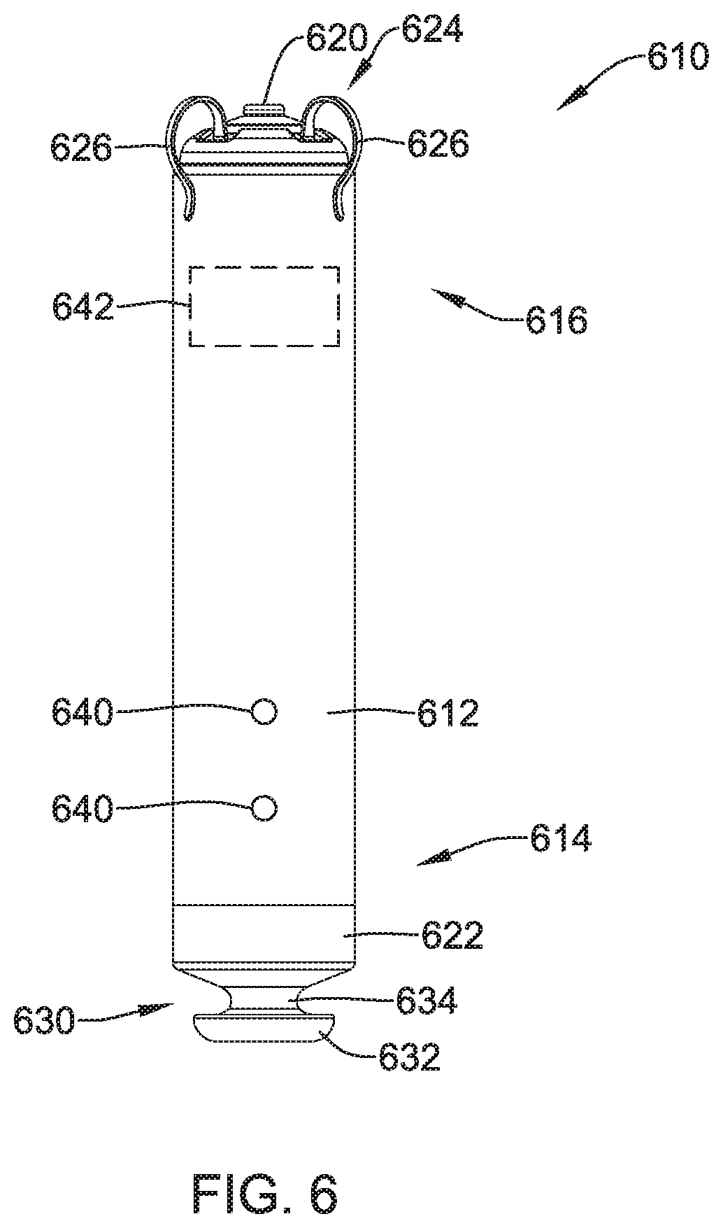
[0074] FIG. 6 is a side view of an illustrative implantable leadless cardiac pacemaker (LCP) 610. The LCP 610 may be similar in form and function to the LCP 100 described above. The LCP 610 may include any of the modules and/or structural features described above with respect to the LCP 100. The LCP 610 may include a shell or housing 612 having a proximal end 614 and a distal end 616. The illustrative LCP 610 includes a first electrode 620 secured relative to the housing 612 and positioned adjacent to the distal end 616 of the housing 612, and a second electrode 622 secured relative to the housing 612 and positioned adjacent to the proximal end 614 of the housing 612. In some cases, the housing 612 may include a conductive material and may be insulated along a portion of its length. A section along the proximal end 614 may be free of insulation so as to define the second electrode 622. The electrodes 620, 622 may be sensing and/or pacing electrodes to provide electro-therapy and/or sensing capabilities. The first electrode 620 may be capable of being positioned against or may otherwise contact the cardiac tissue of the heart while the second electrode 622 may be spaced away from the first electrode 620. The first and/or second electrodes 620, 622 may be exposed to the environment outside the housing 612 (e.g. to blood and/or tissue).
[0075] In some cases, the LCP 610 may include a pulse generator (e.g., electrical circuitry) and a power source (e.g., a battery) within the housing 612 to provide electrical signals to the electrodes 620, 622 to control the pacing/sensing electrodes 620, 622. While not explicitly shown, the LCP 610 may also include a communications module, an electrical sensing module, a mechanical sensing module, and/or a processing module, and the associated circuitry, similar in form and function to the modules 102, 106, 108, 110 described above. The various modules and electrical circuitry may be disposed within the housing 612.
[0076] In the example shown, the LCP 610 includes a fixation mechanism 624 proximate the distal end 616 of the housing 612. The fixation mechanism 624 is configured to attach the LCP 610 to a wall of the heart H, or otherwise anchor the LCP 610 to the anatomy of the patient. As shown in FIG. 6, in some instances, the fixation mechanism 624 may include one or more, or a plurality of hooks or tines 626 anchored into the cardiac tissue of the heart H to attach the LCP 610 to a tissue wall. In other instances, the fixation mechanism 624 may include one or more, or a plurality of passive tines, configured to entangle with trabeculae within the chamber of the heart H and/or a helical fixation anchor configured to be screwed into a tissue wall to anchor the LCP 610 to the heart H. These are just examples.
[0077] The LCP 610 may further include a docking member 630 proximate the proximal end 614 of the housing 612. The docking member 630 may be configured to facilitate delivery and/or retrieval of the LCP 610. For example, the docking member 630 may extend from the proximal end 614 of the housing 612 along a longitudinal axis of the housing 612. The docking member 630 may include a head portion 632 and a neck portion 634 extending between the housing 612 and the head portion 632. The head portion 632 may be an enlarged portion relative to the neck portion 634. For example, the head portion 632 may have a radial dimension from the longitudinal axis of the LCP 610 that is greater than a radial dimension of the neck portion 634 from the longitudinal axis of the LCP 610. In some cases, the docking member 630 may further include a tether retention structure (not explicitly shown) extending from or recessed within the head portion 632. The tether retention structure may define an opening configured to receive a tether or other anchoring mechanism therethrough. The retention structure may take any shape that provides an enclosed perimeter surrounding the opening such that a tether may be securably and releasably passed (e.g. looped) through the opening. In some cases, the retention structure may extend though the head portion 632, along the neck portion 634, and to or into the proximal end 614 of the housing 612. The docking member 630 may be configured to facilitate delivery of the LCP 610 to the intracardiac site and/or retrieval of the LCP 610 from the intracardiac site. While this describes one example docking member 630, it is contemplated that the docking member 630, when provided, can have any suitable configuration.
[0078] In some cases, the LCP 610 may include one or more pressure sensors 640 coupled to or formed within the housing 612 such that the pressure sensor(s) is exposed to and/or otherwise operationally coupled with the environment outside the housing 612 to measure blood pressure within the heart. In some cases, the pressure sensor 640 may be coupled to an exterior surface of the housing 612. In other cases, the pressures sensor 640 may be positioned within the housing 612 with a pressure acting on the housing and/or a port on the housing 612 to affect the pressure sensor 640. If the LCP 610 is placed in the left ventricle, the pressure sensor(s) 640 may measure the pressure within the left ventricle. If the LCP 610 is placed in another portion of the heart (such as one of the atriums or the right ventricle), the pressures sensor(s) may measure the pressure within that portion of the heart.
[0079] The pressure sensor(s) 640 may include a MEMS device, such as a MEMS device with a capacitive diaphragm or a piezoresistive diaphragm, a piezoelectric sensor, a condenser, a micromanometer, or any other suitable sensor adapted for measuring cardiac pressure. The pressures sensor(s) 640 may be part of a mechanical sensing module described herein. It is contemplated that the pressure measurements obtained from the pressures sensor(s) 640 may be used to generate a pressure curve over cardiac cycles. Frequent pressure monitoring may be beneficial for management of heart failure patients. Frequent pressure monitoring may also be useful for patients with chronic heart disease, hypertension, regurgitation, valve issues, and other issues. It is further contemplated that the pressure sensor(s) 640 may be used for monitoring respiration and associated diseases (e.g., chronic obstructive pulmonary disease (COPD), etc.). The pressure readings may be taken in combination with a cardiac chamber volume measurement such as impedance measurements (e.g. the impedance between electrodes 620 and 622) to generate a pressure-impedance loop for one or more cardiac cycles. The impedance may be a surrogate for chamber volume, and thus the pressure-impedance loop may be representative of a pressure-volume loop for a chamber of the heart H.
[0080] The LCP 610 may further include a gyroscope 642. The gyroscope 642 may be positioned within the housing 612 along with the processing module, battery, and/or other modules. It is contemplated that the gyroscope 642 may be 1-axis, a 2-axis, or a 3-axis gyroscope, as desired. The gyroscope 642 may be selected to balance power consumption, physical size and usage. For example, a 3-axis gyroscope may provide the most accurate data regarding the movement of the left ventricle, but may also consume the most power. In order to manage power consumption, the number of axes may be limited. Alternatively, or additionally, to further manage power consumption, the gyroscope 642 may be enabled for only certain short periods of certain heart cycle (e.g., triggered by a heart sound trigger and enabled for only a short time period, only for 1 of every N cycles, etc.) The pressure sensor 640 and/or electrodes 620, 622 may provide information to the circuitry regarding the cardiac cycle to allow the gyroscope 642 to be selectively activated at useful times, such as during a maximum contraction of the heart (at max positive dP/dt) and/or during max filling (at max negative dP/dt). In some cases, the gyroscope 642 may continuously acquire data related to the movement of the heart, at least for a period of time.
[0081] In some embodiments, the gyroscope 642 may be a stand-alone gyroscope. An illustrative gyroscope suitable for use inside the housing 612 of the LCP 610 is the ADXRS290 manufactured by Analog Devices.TM.. The ADXRS290 is a MEMS device which has an approximate size of 5.times.5.times.1.2 millimeters. In other embodiments, the gyroscope 642 may be integrated with an accelerometer to provide a full inertial measurement unit (IMU). For example, the inclusion of a 3-axis accelerometer with the gyroscope 642 may together provide six degrees of freedom. An illustrative device including a 3-axis gyro and accelerometer is the MC7030 iGyro.TM. manufactured by mCube.TM.. The MC7030 iGyro.TM. also includes a 3-axis magnetometer sensor (in addition to the 3-axis accelerometer and the 3-axis gyroscope) giving the device nine degrees of freedom. These are just example devices that are suitable for use in LCP 610. However, it is contemplated that any suitable gyroscope may be used in or with the LCP 610.
[0082] It may be desirable to position the gyroscope 642 as close to the left ventricle apex as possible, although a location near the apex on the free-wall may be sufficient. In some cases, it may be desirable to use magnetic resonance imaging (MRI) or ultrasound to determine the optimal location within the heart for measuring cardiac twist. The optimum location for measuring cardiac twist may be different from the optimum location for implantation of the LCP 610 for performing cardiac pacing. In such an instance, it may be desirable to provide the gyroscope 642 as a separate component from the LCP 610 or as a tethered system that can be attached to the LCP 610 (see FIG. 7B).
[0083] FIG. 7A is a partial cross-sectional plan view of the example leadless cardiac pacing device 610 implanted within a left ventricle LV of the heart H during ventricular filling. The right ventricle RV, right atrium RA, left atrium LA, and aorta A are also illustrated. As detailed above, the LCP 610 may include the gyroscope 642 disposed within the housing 612 of the LCP 610. In some cases, a second gyroscope 644 may also be provided. The second gyroscope 644 may be provided as a stand-alone device or as a part of an additional LCP device, as desired. When a second gyroscope is provided, it may be desirable for the first gyroscope 642 to be positioned near the apex of the heart and the second gyroscope 644 to be positioned near the base of the left ventricle, such as shown in FIG. 7A. This may allow two different twist directions to be more readily captured. The second gyroscope 644 may be in wireless communication with the LCP 610 and/or an external device.
[0084] FIG. 7B is another partial cross-sectional plan view of another illustrative leadless cardiac pacing device 650 implanted within a left ventricle LV of the heart H during ventricular filling. The right ventricle RV, right atrium RA, left atrium LA, and aorta A are also illustrated. The illustrative LCP 650 may include the gyroscope 642 provided as a modular tethered system. The gyroscope 642 may be electrically connected to the LCP 650 through a tail or tether 646. This may allow both the gyroscope 642 and the LCP 650 to be positioned in their optimum locations. In some embodiments, a second gyroscope 644 may be provided adjacent to the base of the left ventricle as a stand-alone device or electrically connected to the LCP 650 through a tail or tether 648. In some embodiments, the second gyroscope 644 may be the only gyroscope. In other words, the first gyroscope 642, positioned at the apex, may not be present.
[0085] It is also contemplated that the LCP 650 may itself include a gyroscope, similar to
[0086] LCP 610 of FIG. 7A, and may include a second gyroscope may be electrically connected via a tether (such as the tether 648 illustrated in FIG. 7B). In another example, a single gyroscope may be provided as a stand-alone system in any desired location. The stand-alone gyroscope may be in wired or wireless communication with an implanted LCP or an external device.
[0087] During placement of the gyroscope 642 (either as a part of the LCP 610 or as a stand-alone system), a pressure sensor in the delivery catheter or LCP 610 may be used to correlate pressure and twist. For example, the peak angle of rotation of the twist during systole may generally occur at the same time as the peak pressure (max dP/dt). Thus, in some cases, the gyroscope 642 may be enabled during this time. Also, certain cardiac conditions may be detected by determine the relative measures of pressure and twist. For example, it may be beneficial to determine when max dP/dt is down, whether max twist angle, max twist speed and or other twist parameter are also down or not. In addition, it may be desirable to coordinate torsional measurements with other factors, including, but not limited to: time of day, an accelerometer in the LCP 610 (or other device such an S-ICD, ICM, etc.), a respiratory or cardiac signal (e.g. via transthoracic impedance). In some cases, the gyroscope 642 may be configured to obtain measurements in response to an external device, such as, but not limited to a handheld patient unit or external programmer.
[0088] Normal hearts (e.g., well-functioning hearts) may have a "typical" twist (e.g. degree of rotation, twist vector, and/or speed of rotation) associated with each cardiac cycle. The twist vector may be the axis normal to the plane of the twist. The angular motion (e.g. twist or torsion of the left ventricle), as measured by the gyroscope 642, may be used to help identify a suitable pacing site and/or suitable timing for cardiac resynchronization therapy (CRT). FIG. 8 is a flow chart of an illustrative method 800 for generating a twisting profile of the left ventricle of a heart from data obtained from an implanted LCP with a gyroscope such LCP 610. While the method is described using an LCP having a gyroscope within the housing, it is contemplated that other devices and/or combinations of devices may be used. For example, a second gyroscope (stand-alone or in combination with an LCP) may be used to collect data from a different location in the heart. As described above, the LCP may include a processing module that includes control circuitry configured to control the operation of the LCP. In some instances, the processing module may include separate circuits for therapy delivery, torsion sensing, hemodynamic (e.g. pressure) sensing, and/or volume sensing, although this is not required. It is contemplated that the processing module may further include an additional circuit or algorithm for generating a twisting profile that may be configured to convert the data obtained from one or more gyroscopes into a twist profile. As used herein, a twisting profile may be a temporal progression or point in time of the angular velocity including a single torsion measurement (e.g. max twist angle, max twist speed, etc.), a plurality of torsion measurements obtained over a single cardiac cycle, an average of torsion measurements (either single data points or multiple data points in the same cardiac cycle) obtained over a plurality of cardiac cycles, and/or any other suitable measurement or combination of measurements. In some cases, the twisting profile may be based on any signal characteristic obtained from the gyroscope signals including, but not limited to, based on amplitude, frequency, temporal association, morphology, etc. It is further comtemplated that other characteristics may form the twisting profile, or be extracted from the twisting profile, including, but not limited to the maximum amplitude reached during a cardiac beat, the timing of the maximum amplitude within the beat, the area under curve for the portion of the curve where twist occurs in the abnormal direction, etc.
[0089] As shown at block 802, an optional twisting template using one or more torsion measurements (e.g., degree of rotation and/or speed of rotation) may be generated. The twisting template may be generated at the time of implantation (sometimes using Mill, ultrasound and/or the gyroscope) or at a time point (or plurality of time points) previous to a current measurements. The twist template may characterize the typical twisting action of the patient's heart when the heart is operating in a healthy manner. In some instances, the twist (e.g., torsion) may be measured for both sensed beats and paced beats, and different twisting templates may be generated for each type of beat. In many cases, and because of the different conduction, the twisting action and thus the twisting template is expected to be different for sensed beats (i.e. intrinsic beats) versus paced beats.
[0090] The twist template may be updated at regular, or predefined intervals or based on a detected condition changes (e.g., exercise, heart failure (HF) status, posture, therapy modification, cardiac status, pacing status, etc.), as desired. In some cases, a different twist template may be created, stored and updated for each of a number of predetermined conditions. For example, a twist template may be created, stored and updated for each of several different postures (e.g. lying down, sitting, walking, etc.) Then, during subsequent operation, the LCP may sense a current posture and use the corresponding twist template to for comparison with a currently sensed twisting profile.
[0091] As shown at block 804, the processing module and/or any other circuits of one or more LCPs (and/or other implantable devices) may obtain a torsion measurement using the gyro. The torsion measurements may include, for example, max twist angle, max twist speed, max twist acceleration, twist angle sampled over a time period, twist speed sampled over a time period, twist acceleration sampled over a time period, a twist vector indicating an average, max, min or other twist direction, twist direction sampled over a time period, and/or any other suitable torsion parameter.
[0092] In some instances, the torsion measurement may be made at a first time or during a first time period during a cardiac cycle. The first time or first time period may be triggered using an R wave or an S1 heart sound, although this is not required. In other instances, the first time or first time period may be triggered using the peak pressure (max dP/dt). The data may be stored in a memory of the LCP. In some instances, the data may be stored in a table. In some cases, the data may be transmitted to a remote device, such as another LCP, an S-ICD device, or an external device. The processing module may optionally obtain one or more additional torsion measurements at different times during the same cardiac cycle, as shown at block 806. The one or more torsion measurements may be analyzed to generate a twisting profile, as shown at block 808. In the case where more than one gyroscope has been provided, multiple measurements may be taken and used for analyzing same cardiac cycle. For example, torsional measurements for the apex, base, and/or other location may be taken and used to generate the twisting profile.
[0093] In some instances, the processing module may include circuitry to analyze the data and generate the twisting profile. In other instances, the LCP circuitry may be configured to wirelessly transmit the torsion measurements to a remote or external device, such as, but not limited to, any of the medical or external devices described above. The LCP may communicate with the remote or external device via radiofrequency (RF) signals, inductive coupling, optical signals, acoustic signals, conducted communication signals, and/or any other signals suitable for communication. The remote or external device may then analyze the torsional measurements and generate the twisting profile. In some cases, the generated twisting profile may be communicated back to the LCP.
[0094] It is contemplated that torsion measurements obtained over a plurality (e.g. two or more, five or more, ten or more) of cardiac cycles may be averaged to generate a twisting profile. For example, the LCP circuitry may be configured to record or sample torsion or twisting at the same (or similar) time points in each of a series of cardiac cycles such that the first torsion measurement from a first cardiac cycle can be averaged with the corresponding first torsion measurement from any number of subsequent (or preceding) cardiac cycles. Any other torsional measurements may be similarly average. Averaging the data over a plurality of cardiac cycles may reduce the noise and provide a more robust representation of the twisting profile. In some cases, the averaging may be weighted so that more current torsion measurements are weighted higher than older torsion measurements.
[0095] As shown at block 810, the torsion measurements and/or twisting profile may be analyzed (e.g., in the internal circuitry of the LCP, the circuitry of another device, and/or a physician's analysis) to determine how the heart is currently functioning. In some cases, the twisting profile may be compared to a twisting template, although this is not required. In some cases, a net LV twist below a threshold value may indicate that pacing and/or other therapy can be further optimized. In other instances, a twist velocity below a threshold velocity may indicate that pacing and/or other therapy can be further optimized. In some cases, features extracted from the twisting profile (e.g., twist rate of change) may be used to make treatment decisions or to provide diagnostic information. To save on power, the torsion measurements and/or twisting profile may be based on one axis of a gyroscope (e.g., the perpendicular plane to the normal vector from the LV apex), although more than one axis may be used when desired. The twisting profile may be updated at regular, or predefined intervals.
[0096] If the pacing and/or other therapy can be further optimized, the LCP circuitry may be configured adjust pacing and/or other parameters of the LCP, as shown at block 812. For example, the AV delay and/or VV delay may be adjusted to help improve the twist of the heart. In some cases, the voltage and/or pulse width required to reliably depolarize (capture) the heart may be adjusted. Alternatively, or additionally, the level of fusion may be manipulated by either pacing a marginally earlier or delaying a pace to wait for an intrinsic beat. In some cases, the physical location of the pacing electrode of the LCP may be changed to increase the twist of the heart. It is contemplated that the torsion measurements and/or twisting profile may be used for additional analysis of the cardiac function, as desired.
[0097] FIG. 9 is a diagram 900 illustrating some, but not all, potential uses of one more torsion measurements 902 (e.g. degree of rotation, speed of rotation, and/or features that can be extracted from the torsion measurements, such as, but not limited to rate of change). The torsion measurements 902 may be obtained at a single time in the cardiac cycle (e.g., peak torsion) or a plurality of sample times during the same cardiac cycle. In some cases, the torsion measurements may be obtained over one or more cardiac cycles (either using a single time or plurality of sample times in the same cardiac cycle) at similar times, and the measurements averaged, as described above. A single torsion measurement, a plurality of torsion measurements, a single point averaged over one or more cardiac cycles, and/or a plurality of points each averaged over one or more cardiac cycles may individually or together form a twisting profile of the heart.
[0098] As described above, the torsion measurements may be used for treatment optimization, as shown at block 904. Some pacing parameters that may be manipulated include, but are not limited to capture (CRT effectiveness) 906, AV and/or VV delay 908, level of fusion 910, and/or the pacing site 912. In some instances, the LCP circuitry may be configured to compare or correlate the torsion measurements and/or twisting profile with other parameters, as shown at block 914. In some cases, this correlation may be performed by other external devices described herein, or the LCP itself. Some illustrative parameters that the torsion measurements and/or twisting profile may be compared or correlated with may include, but are not limited to, dP/dt (change in pressure with respect to time) 916, pressure-volume (PV) loops 918, volume-volume (VV) loops 920, heart sounds 922, an ECG attribute (e.g., QRS signal width) 924, blood flow 926, and/or cardiac dimensions (chamber volume) 928. Other parameters may include, but are not limited to cardiovascular pressure (e.g., ventricular pressure), heart sounds, impedance, cardiac shorting (using a doubly integrated acceleration signal in combination with a twist vector parameter), and/or respiration. The correlation between torsion measurements and/or twisting profile and other parameters may provide the LCP and/or physician with further insight regarding the mechanical performance of the heart and/or facilitate the tracking of various parameters over time. It is further contemplated that pressure or other parameters may be used to adjust pacing and/or other therapy to achieve a desired or optimal angular profile for a patient.
[0099] As noted above, the torsion measurements 902 may be used to generate twisting templates that correspond to each of a plurality of different states or conditions (e.g., activity level, HF status, posture, respiration rate, heart rate, etc.) that the patient may be in, as shown at block 930. For example, a twist template may be created, stored and updated for each of several different postures (e.g. lying down, sitting, walking, etc.) Then, during subsequent operation, the LCP may sense a current posture and use the corresponding twist template for comparison with a currently sensed twisting profile.
[0100] Additionally, or alternatively, the torsion measurements may be used to facilitate rhythm discrimination. For example, as shown at block 932, the torsion measurements and/or twisting profile may be correlated to different arrhythmias. When the heart rhythm is abnormal, the twisting profile is also expected to be abnormal. In some cases, the twist angle and/or early diastolic twisting may be correlated to a particular arrhythmias type. In some cases, the torsion measurements may be correlated to certain physiological variable such as preload, afterload, contractility, etc. Increased preload can be indicated by an increased peak twist angle and a decreased peak twist velocity. Increased afterload can be indicated by a decreased peak twist angle and a decreased peak twist velocity. An increased contractility can be indicated by an increased peak twist angle and increased peak twist velocity. These and other physiological variables can depending on the type of arrhythmia, and thus can be used to discriminate between types of arrhythmias. In one example, a marker for ventricular tachycardia (VT) may be a substantial drop in afterload relative to a supraventricular tachycardia (SVT), as shown at block 934.
[0101] In some cases, the torsion measurements and/or twisting profiles may be used to help confirm an event detection by the LCP and/or an external device such as an SICD or remote programmer, as shown at block 936. For example, the torsion measurements and/or twisting profiles may supplement an LCP's or S-ICD' s rhythm discrimination algorithm by confirming an initial detection by other means (e.g. by ECG signals). In some cases, the confirmation of an event may result in the delivery or adjustment of a therapy delivered by the LCP and/S-ICD. For example, the LCP and/or S-ICD may deliver an ATP therapy when one or more twisting parameters indicate a tachyarrhythmia that is treatable with ATP therapy.
[0102] In some cases, the torsion measurements and/or twisting profile may be used for diagnostic monitoring of acute and/or chronic conditions. The torsion measurements and/or twisting profile may be combined with other diagnostic parameters such as pressure, chamber volume, etc. to perform the diagnostic monitoring. FIG. 10 is a diagram 1000 illustrating some, but not all, potential uses of one more torsion measurements 1002 (e.g. degree of rotation, speed of rotation, and/or features that can be extracted from a plot of the torsion measurements, such as, but not limited to rate of change) in diagnostic monitoring. In a first example, the torsion measurements and/or twisting profile may be used to monitor systolic and/or diastolic heart failure in patients, as shown at block 1004. The recoil rate (e.g., untwisting velocity) is inversely related to the time constant of LV pressure decay. As such, the recoil rate may be used in monitoring diastolic dysfunction. In some cases, the recoil rate may be a target metric for optimization. For example, when a patient is sleeping, the recoil rate may be optimized for relaxation. In diastolic heart failure, the twist angle may remain neutral or increase and the peak twist velocity may remain neutral or decrease relative to normal. In some cases, the recoil rate and QRS width may be combined to provide a measure of dyssynchrony.
[0103] The maximum twisting rate may be similar to the maximum dP/dt and can be used for the monitoring of patients' systolic function. In systolic heart failure, the peak twist angle as well as the peak twist velocity may decrease relative to normal. Further, LV twisting and untwisting rates are reduced in patients with systolic dysfunction and depressed ejection fraction, but not in those with diastolic dysfunction and preserved ejection fraction.
[0104] In another example, the torsion measurements and/or twisting profile may be used to monitor aortic stenosis, as shown at block 1006. When aortic stenosis occurs, the peak twist angle may remain neutral or increase and the peak twist velocity may decrease relative to normal.
[0105] In another example, the torsion measurements and/or twisting profile may be used to monitor mitral regurgitation, as shown at block 1008. When mitral regurgitation occurs, the peak twist angle may decrease and the peak twist velocity may decrease relative to normal.
[0106] In another example, the torsion measurements and/or twisting profile may be used to monitor transmural infarction, as shown at block 1010. When transmural infarction occurs, the peak twist angle may decrease and the peak twist velocity may decrease relative to normal.
[0107] In another example, the torsion measurements and/or twisting profile may be used to monitor subendocardial ischemia, as shown at block 1012. When subendocardial ischemia occurs, the peak twist angle may remain neutral and the peak twist velocity may remain neutral or decrease relative to normal.
[0108] In another example, the torsion measurements and/or twisting profile may be used to monitor various types of cardiomyopathy, as shown at block 1014. When dilated cardiomyopathy occurs, the peak twist angle may decrease and the peak twist velocity may decrease relative to normal. When hypertrophic cardiomyopathy occurs, the peak twist angle may remain neutral or increase and the peak twist velocity may decrease relative to normal. Patients with hypertrophic cardiomyopathy (HC) show increased peak LV twist, onset of torsion recoil closer to aortic valve closure (e.g., reduction in time between S2 and recoil onset), and delayed peak untwist velocity. When restrictive cardiomyopathy occurs, the peak twist angle may remain neutral or increase and the peak twist velocity may remain neutral relative to normal.
[0109] In another example, the torsion measurements and/or twisting profile may be used to monitor constrictive pericarditis, as shown at block 1018. When constrictive pericarditis occurs, the peak twist angle may decrease and the peak twist velocity may decrease relative to normal. These illustrative cardiac diseases are not intended to be inclusive of all of the diseases and/or conditions that can be monitored using torsion measurements and/or twisting profiles. Subendocardial dysfunction can appear with other diseases as well.
[0110] It is further contemplated that the torsion measurements and/or twisting profiles may be used to monitor ejection fraction, as shown at block 1016. As described herein, the twist aids in LV ejections and accounts for a large portion of the volume of blood ejected. An abnormal or substandard twist may be associated with an inadequate ejection fraction. As compared with myocardial infarction (MI) patients, heart failure patients present an even more pronounced impairment of LV mechanics, irrespective of the HF etiology as a result of reduction of both LV basal and apical rotation. In some cases, the peak LV twist angle may have a linear relationship with the left ventricle ejection fraction. Thus, the gyroscope measurements may be able to calculate the ejection fraction based on the peak LV twist angle. Therapy may be changed accordingly.
[0111] Those skilled in the art will recognize that the present disclosure may be manifested in a variety of forms other than the specific examples described and contemplated herein. For instance, as described herein, various examples include one or more modules described as performing various functions. However, other examples may include additional modules that split the described functions up over more modules than that described herein. Additionally, other examples may consolidate the described functions into fewer modules. Accordingly, departure in form and detail may be made without departing from the scope and spirit of the present disclosure as described in the appended claims.
* * * * *
D00000
D00001
D00002
D00003
D00004
D00005
D00006
D00007
D00008
D00009
D00010
D00011
XML
uspto.report is an independent third-party trademark research tool that is not affiliated, endorsed, or sponsored by the United States Patent and Trademark Office (USPTO) or any other governmental organization. The information provided by uspto.report is based on publicly available data at the time of writing and is intended for informational purposes only.
While we strive to provide accurate and up-to-date information, we do not guarantee the accuracy, completeness, reliability, or suitability of the information displayed on this site. The use of this site is at your own risk. Any reliance you place on such information is therefore strictly at your own risk.
All official trademark data, including owner information, should be verified by visiting the official USPTO website at www.uspto.gov. This site is not intended to replace professional legal advice and should not be used as a substitute for consulting with a legal professional who is knowledgeable about trademark law.