Catheter Insertion Device
Huang; Heqing ; et al.
U.S. patent application number 16/490023 was filed with the patent office on 2020-01-02 for catheter insertion device. The applicant listed for this patent is C. R. Bard, Inc.. Invention is credited to Weng K. Chan, Jianjiang Chen, Heqing Huang.
| Application Number | 20200001051 16/490023 |
| Document ID | / |
| Family ID | 63369605 |
| Filed Date | 2020-01-02 |


View All Diagrams
| United States Patent Application | 20200001051 |
| Kind Code | A1 |
| Huang; Heqing ; et al. | January 2, 2020 |
Catheter Insertion Device
Abstract
A tool (10) for inserting a catheter (22) into a body of a patient is provided. The tool (10) comprises: a housing (12, 40, 50) in which at least a portion of the catheter (22) is initially disposed; a needle (16) distally extending from the housing (12, 40, 50), at least a portion of the catheter (22) disposed over the needle (16); a guidewire (32) initially disposed within the needle (16) partially; and an advancement assembly (20) for distally advancing the catheter (22). The housing (12, 40, 50) comprises: a first portion (12A, 42, 52) comprising a distal part (42A, 52A) and a proximal part (42B); and a second portion (12B, 44, 54) engaged with the first portion (12A, 42, 52), wherein the distal part (42A, 52A) of the first portion (12A, 42, 52) is configured to be able to distally slide with respect to the second portion (12B, 44, 54) to release the engagement between the first portion (12A, 42, 52) and the second portion (12B, 44, 54). The advancement assembly (20) includes a safety cap (26) which is initially disposed over the needle (16) and is configured to be locked to the housing (12, 40, 50) when distally sliding to a position of isolating the tip of the needle (16) within the safety cap (26).
| Inventors: | Huang; Heqing; (Shanghai, CN) ; Chen; Jianjiang; (Shanghai, CN) ; Chan; Weng K.; (Shanghai, CN) | ||||||||||
| Applicant: |
|
||||||||||
|---|---|---|---|---|---|---|---|---|---|---|---|
| Family ID: | 63369605 | ||||||||||
| Appl. No.: | 16/490023 | ||||||||||
| Filed: | March 1, 2017 | ||||||||||
| PCT Filed: | March 1, 2017 | ||||||||||
| PCT NO: | PCT/CN2017/075370 | ||||||||||
| 371 Date: | August 29, 2019 |
| Current U.S. Class: | 1/1 |
| Current CPC Class: | A61M 25/0097 20130101; A61M 2025/09116 20130101; A61M 25/0625 20130101; A61M 2025/0177 20130101; A61M 25/0136 20130101; A61M 25/09041 20130101; A61M 25/0693 20130101; A61M 25/01 20130101; A61M 25/09 20130101; A61M 25/06 20130101; A61M 25/0618 20130101; A61M 25/0631 20130101 |
| International Class: | A61M 25/06 20060101 A61M025/06 |
Claims
1. A catheter insertion tool, comprising: a housing; a needle distally extending from the housing; and a safety cap slidable along the needle, wherein the safety cap: is configured to be locked to the housing when distally sliding to a position of isolating the tip of the needle within the safety cap, and includes a first portion wrapping the needle and a second portion slidably attached to a rail, the rail being an integral part of or fixated to the housing.
2. (canceled)
3. The catheter insertion tool according to claim 1, wherein the safety cap is locked to the housing when distally sliding to the position of isolating the tip of the needle within the safety cap by means of being locked to the rail.
4. The catheter insertion tool according to claim 3, further comprising a catheter hub which is connected to the safety cap until the safety cap is locked to the housing when distally sliding to the position of isolating the tip of the needle.
5. The catheter insertion tool according to claim 4, wherein the first portion of the safety cap comprises at least two fingers which are configured to be biased radially toward an inner surface of the catheter hub when the stem of the needle extends through the first portion of the safety cap and to be released from the biased position when the safety cap distally slides to the position of isolating the tip of the needle.
6. The catheter insertion tool according to claim 5, wherein each of the at least two fingers includes a protrusion which is inserted into a groove disposed on the inner surface of the catheter hub when the at least two fingers are biased radially toward the inner surface of the catheter hub when the stem of the needle extends through the first portion of the safety cap.
7. The catheter insertion tool according to claim 4, wherein the first portion of the safety cap comprises at least two fingers remain in the same position when the stem of the needle extends through the first portion of the safety cap and when the safety cap distally slides to the position of isolating the tip of the needle.
8. The catheter insertion tool according to claim 7, wherein each of the at least two fingers includes a protrusion which is inserted into a recess disposed on the inner surface of the catheter hub.
9. The catheter insertion tool according to claim 6, wherein the proximal side of the protrusion forms an obtuse angle relative to the surface of the finger where the proximal extends from the finger.
10. The catheter insertion tool according to claim 1, wherein the safety cap is locked the housing at a first location and the tip of the needle is isolated within a second location of the safety cap when the safety cap slides to the position of isolating the tip of the needle within the safety cap, the first position being distally spaced from the second position.
11. The catheter insertion tool according to claim 1, wherein a tactile sensation for a clinician is produced when the safety cap is locked to the housing.
12. The catheter insertion tool according to claim 2, wherein the second portion of the safety cap is a lever, the lever includes two vertical walls respectively extending from the two sides of a surface of the lever facing the rail, each of the two vertical walls has a horizontal part with a protrusion, which protrusion is locked within a notch formed on the rail so as to lock the safety cap to the housing when the safety cap distally slides to the position of isolating the tip of the needle within the safety cap.
13. The catheter insertion tool according to claim 12, wherein the notch is formed between two prominent bumps disposed on the rail.
14. The catheter insertion tool according to claim 13, wherein the proximal one of the two bumps has an inclined slope at the proximal side and is substantially vertical to the surface of the rail at the distal side.
15. The catheter insertion tool according to claim 13, wherein the distal one of the two bumps is raised higher from the surface of the rail than the proximal one of the two bumps.
16. The catheter insertion tool according to claim 12, wherein the vertical walls extends throughout the full length of the lever, and the horizontal part is shorter than the full length of the lever.
17-50. (canceled)
51. A tool for inserting a catheter into a body of a patient, comprising: a housing in which at least a portion of the catheter is initially disposed; a needle distally extending from the housing, at least a portion of the catheter dispose over the needle; a guidewire initially disposed within the needle partially; an advancement assembly for distally advancing the catheter; and a septum disposed within the advancement assembly, the septum comprising a circular end portion, and a tubular portion extending from a peripheral of the end portion.
52-58. (canceled)
59. A tool for inserting a catheter into a body of a patient, comprising: a housing in which at least a portion of the catheter is initially disposed; a needle distally extending from the housing, at least a portion of the catheter disposed over the needle; an advancement assembly for distally advancing the catheter; a guidewire initially disposed within the needle partially; and a guidewire advance device for driving the guidewire, the guidewire advance device comprising: a pushing block, including a hole extending through the pushing block from a top surface to a bottom surface of the pushing block, wherein a sidewall of the hole includes a planar curve; and a rail including a groove aligned with the hole in the longitudinal direction of the catheter insertion tool.
60-64. (canceled)
65. A tool for inserting a catheter into a body of a patient, comprising: a housing in which at least a portion of the catheter is initially disposed; a needle distally extending from the housing, at least a portion of the catheter disposed over the needle; a guidewire initially disposed within the needle partially; and an advancement assembly for distally advancing the catheter, wherein the housing comprises: a first portion comprising a distal part and a proximal part; and a second portion engaged with the first portion, wherein: the distal part of the first portion is configured to be able to distally slide with respect to the second portion to release the engagement between the first portion and the second portion, and the advancement assembly includes a safety cap which is initially disposed over the needle and is configured to be locked to the housing when distally sliding to a position of isolating the tip of the needle within the safety cap.
66. The tool for inserting a catheter into a body of a patient according to claim 65, wherein the engagement of the first and second portions of the housing is released in preparation for sliding the safety cap to the position isolating the tip of the needle within safety cap.
Description
TECHNICAL FIELD
[0001] The present invention relates to medical devices, more particularly, a catheter insertion device for inserting a catheter into a body of a patient.
BRIEF SUMMARY
[0002] Embodiments of the present invention are directed to an insertion tool for inserting a catheter or other tubular medical device into a body of a patient. The insertion tool in one embodiment integrates needle insertion, guidewire advancement, a needle distally extending from the housing and catheter insertion in a single device to provide for a catheter deployment procedure.
[0003] In one embodiment, the catheter insertion tool of the present invention comprises a housing, a safety cap slidable along the needle, wherein the safety cap is configured to be locked to the housing when distally sliding to a position of isolating the tip of the needle within the safety cap.
[0004] In an embodiment, the safety cap includes a first portion wrapping the needle and a second portion slidably attached to a rail, the rail being an integral part of or fixated to the housing. In an alternative embodiment, the catheter insertion tool further comprises a catheter hub which is connected to the safety cap until the safety cap is locked to the housing when distally sliding to the position of isolating the tip of the needle.
[0005] In one embodiment, the housing of the catheter insertion tool of the present invention comprises a first portion comprising a distal part and a proximal part, and a second portion engaged with the first portion, wherein the distal part of the first portion is configured to be able to distally slide with respect to the second portion to release the engagement between the first portion and the second portion.
[0006] In an alternative embodiment, the proximal part of the first portion of the housing is fixated to the second portion. In an alternative embodiment, a hook is disposed on an inner surface of the distal part of the first portion, the hook having a tip extending toward the proximal end of the housing, and a slot is disposed on the second housing portion, wherein the slot receives the hook when the first portion and the second portion are engaged, and the hook is released from the slot when the distal part of the first portion is slid distally such that the first portion is released from the second portion.
[0007] In an alternative embodiment, wherein the proximal end of the distal part of the first portion of the housing is configured to be axially locked to the second portion of the housing, and the distal part of the first portion is configured to be able to distally slide with respect to the second portion when the locking between the proximal end of the distal part of the first portion and the second portion is released, so as to release the engagement between the first portion and the second portion. In an alternative embodiment, the proximal end of the distal part of the first portion is flexible and is biased toward the second portion when the proximal end of the distal part of the first portion is axially locked to the second portion. In an alternative embodiment, the proximal end of the distal part of the first portion is biased toward the second portion by a slider, and wherein when the slider is distally moved to a certain position, the proximal end of the distal part of the first portion is unbiased and the locking between the proximal end of the distal part of the first portion and the second portion is released.
[0008] In an alternative embodiment, a first protrusion extends from the proximal end of the distal part toward the second portion of the housing, and a second protrusion extends from the second portion toward the proximal end of the distal part of the first portion of the housing, and when the proximal end of the distal part of the first portion is biased toward the second portion and the first protrusion is proximal relative to the second protrusion, the proximal end of the distal part of the first portion is axially locked to the second portion.
[0009] In one embodiment, a septum for a catheter insertion tool of the present invention comprises a cylindrical main body and a first protrusion which extends from a central portion of a top surface of the main body.
[0010] In an alternative embodiment, the septum of the present invention further includes a slit formed within the septum along the longitudinal axis of the septum. Alternatively, the slit is formed within the first protrusion. Alternatively, the slit extends through the septum. Alternatively, the slit is enlarged when a needle extends through the slit and is closed when the needle is withdrawn from the septum. Alternatively, the outer diameter of the main body of the septum is larger than the inner diameter of a lumen of the catheter insertion tool before the septum is installed in the lumen. In an alternative embodiment, the septum of the present invention further includes a second protrusion which extends from a central portion of a bottom surface of the main body opposite to the top surface.
[0011] In one embodiment, a septum for a catheter insertion tool of the present invention comprises a circular end portion and a tubular portion extending from the peripheral of the circular end portion. In an alternative embodiment, the septum of the present invention further includes a protrusion extending from a central portion of a surface of the circular end portion opposite to the tubular portion. Alternatively, a slit is formed within the end portion. Alternatively, the slit is formed within the protrusion. Alternatively, the slit extends through the end portion. Alternatively, the slit is enlarged when a needle extends through the slit and is closed when the needle is withdrawn.
[0012] In one embodiment, a guidewire advancement device for a catheter insertion tool of the present invention, comprising: a pushing block, including a hole extending through the pushing block from a top surface to a bottom surface of the pushing block, wherein a first sidewall of the hole is in the form of a planar curve; and a rail including a groove aligned with the hole in the longitudinal direction of the catheter insertion tool. In an alternative embodiment, the hole has a second sidewall opposite to the first sidewall is straight, the minimum distance between the first and second sidewalls is wide enough to allow free longitudinal movement of a guidewire and is narrow enough to restrict sway of the guidewire.
[0013] In an alternative embodiment, the guidewire advancement device further comprises an anchor point to which one end of a guidewire is fixated, and the guidewire proximally extends from the anchor point, enters the hole via a first potion of the rail, extends away from the hole and distally extends into a second portion of the rail.
[0014] In one embodiment, a guidewire advancement device for a catheter insertion tool of the present invention comprises a wheel and a rack configured to rotate the wheel such that a guidewire is driven around the wheel. Alternatively, the guidewire advancement device further comprises a gear coaxially fixed to the wheel, wherein the rack includes teeth to engage the gear. Alternatively, the guidewire advancement device further comprises at least one idler for restricting the guidewire against the peripheral surface of the wheel. Alternatively, the guidewire advancement device further comprises a pipe rail for guiding movement of the guidewire.
[0015] In one embodiment, the insertion tool of the present invention comprises a housing in which at least a portion of the catheter is initially disposed, a needle distally extending from the housing, at least a portion of the catheter disposed over the needle, and an advancement assembly for distally advancing the catheter, wherein the housing comprises a first portion comprising a distal part and a proximal part and a second portion engaged with the first portion, wherein the distal part of the first portion is configured to be able to distally slide with respect to the second portion to release the engagement between the first portion and the second portion, and wherein the advancement assembly includes a safety cap which is initially disposed over the needle and is configured to be locked to the housing when distally sliding to a position of isolating the tip of the needle within the safety cap. In an alternative embodiment, the engagement of the first and second portions of the housing is released in preparation for sliding the safety cap to the position isolating the tip of the needle within the safety cap.
[0016] These and other features of embodiments of the present invention will become more fully apparent from the following description and appended claims, or may be learned by the practice of embodiments of the invention as set forth hereinafter.
BRIEF DESCRIPTION OF THE DRAWINGS
[0017] A more detailed description of the present disclosure will be rendered by reference to specific embodiments thereof that are illustrated in the appended drawings. It is appreciated that these drawings depict only typical embodiments of the invention and are therefore not to be considered limiting of its scope. Example embodiments of the invention will be described and explained with additional specificity and detail through the use of the accompanying drawings in which:
[0018] FIG. 1 is a perspective view of a insertion tool according to one embodiment of the present invention;
[0019] FIG. 2 is a top view of the cross section of the insertion tool of FIG. 1;
[0020] FIGS. 3A and 3B are various exploded views of the insertion tool of FIG. 1 and FIG. 2;
[0021] FIGS. 4A-4C are side views of a housing of the catheter insertion tool according to one embodiment of the present invention;
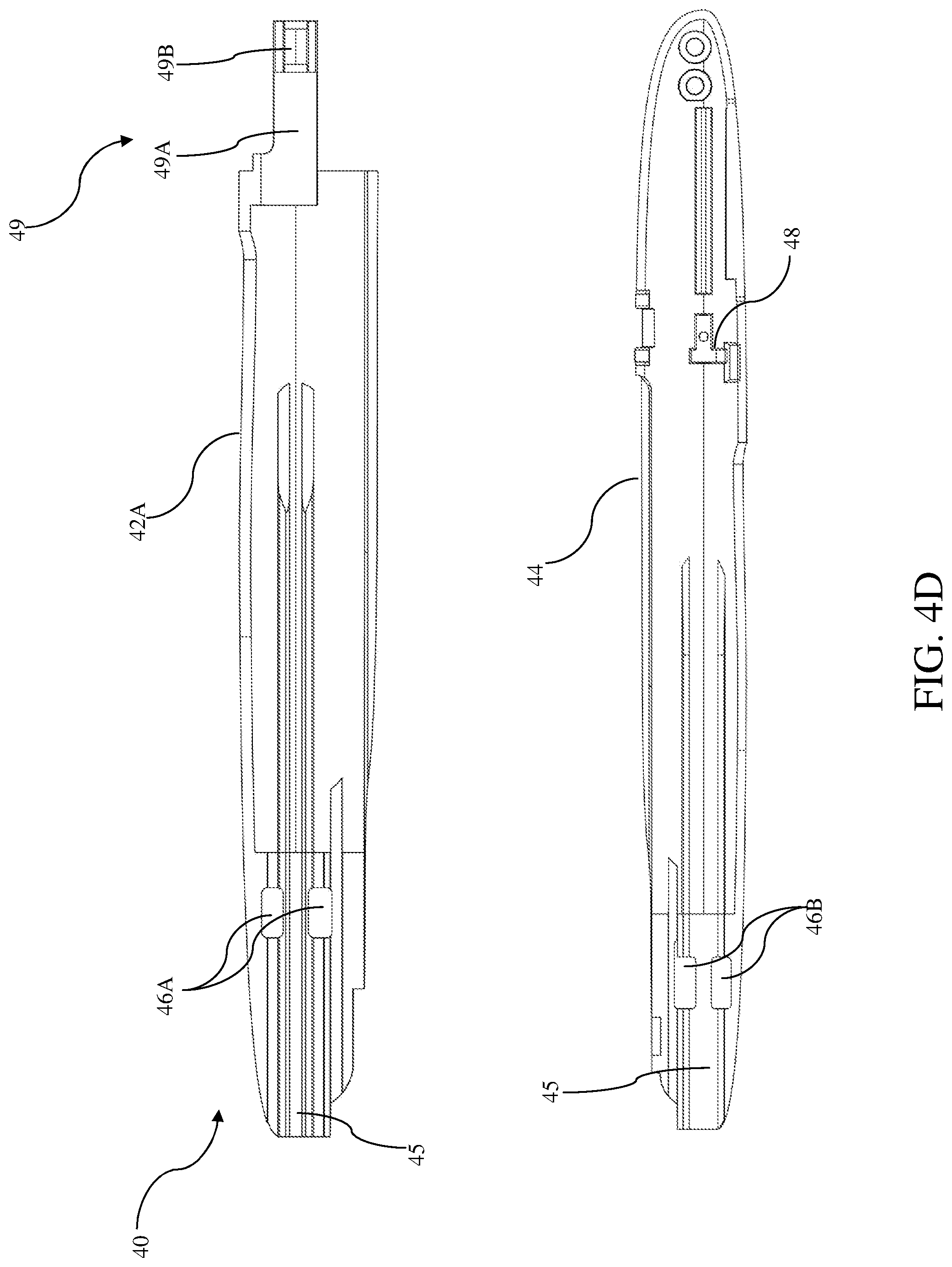
[0022] FIG. 4D shows the inner surface of the housing of FIGS. 4A-4C;
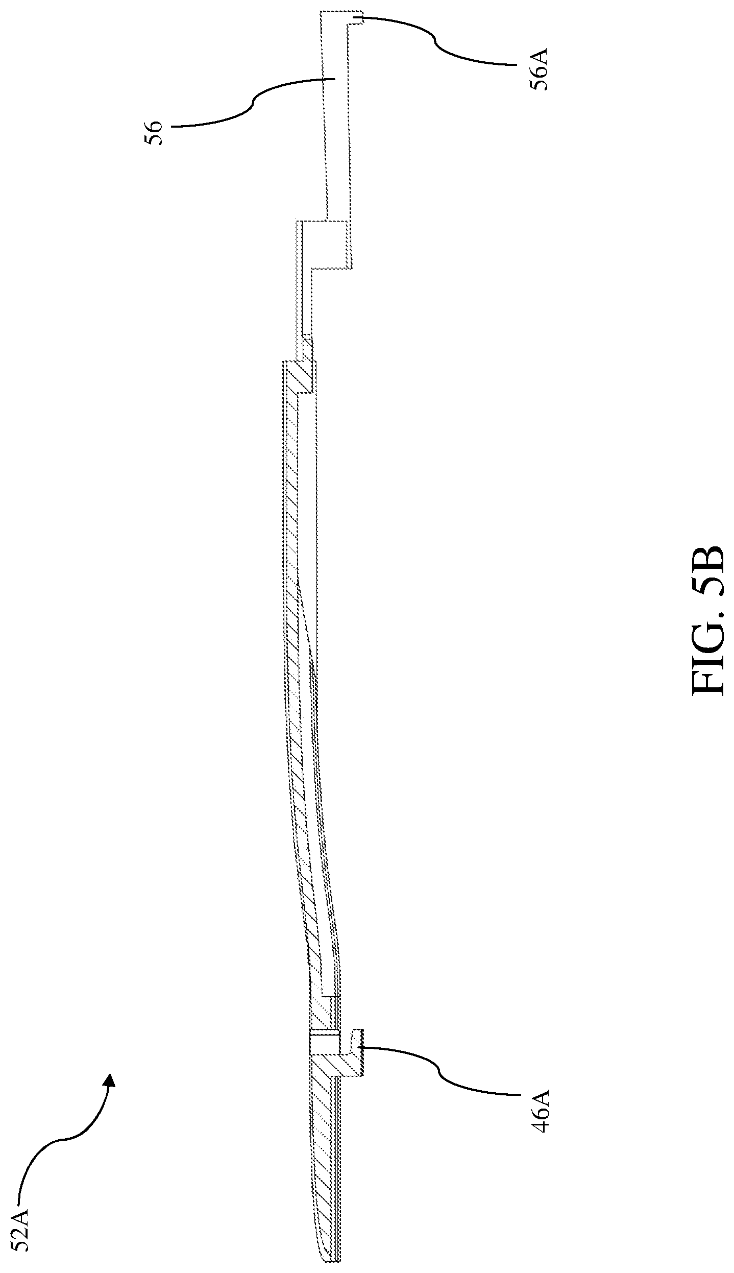
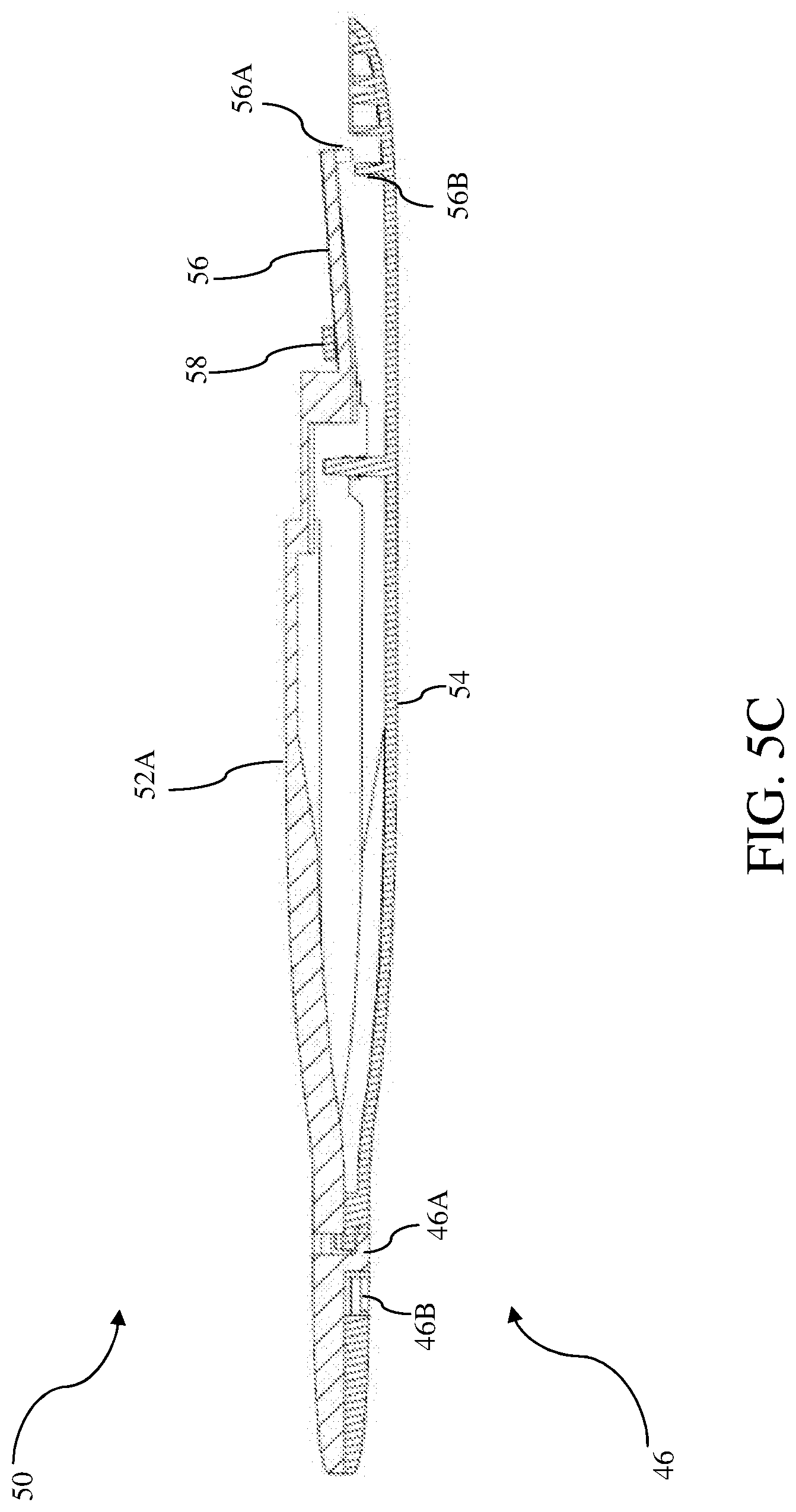
[0023] FIGS. 5A-5C are side views of a housing of the catheter insertion tool according to one embodiment of the present invention;
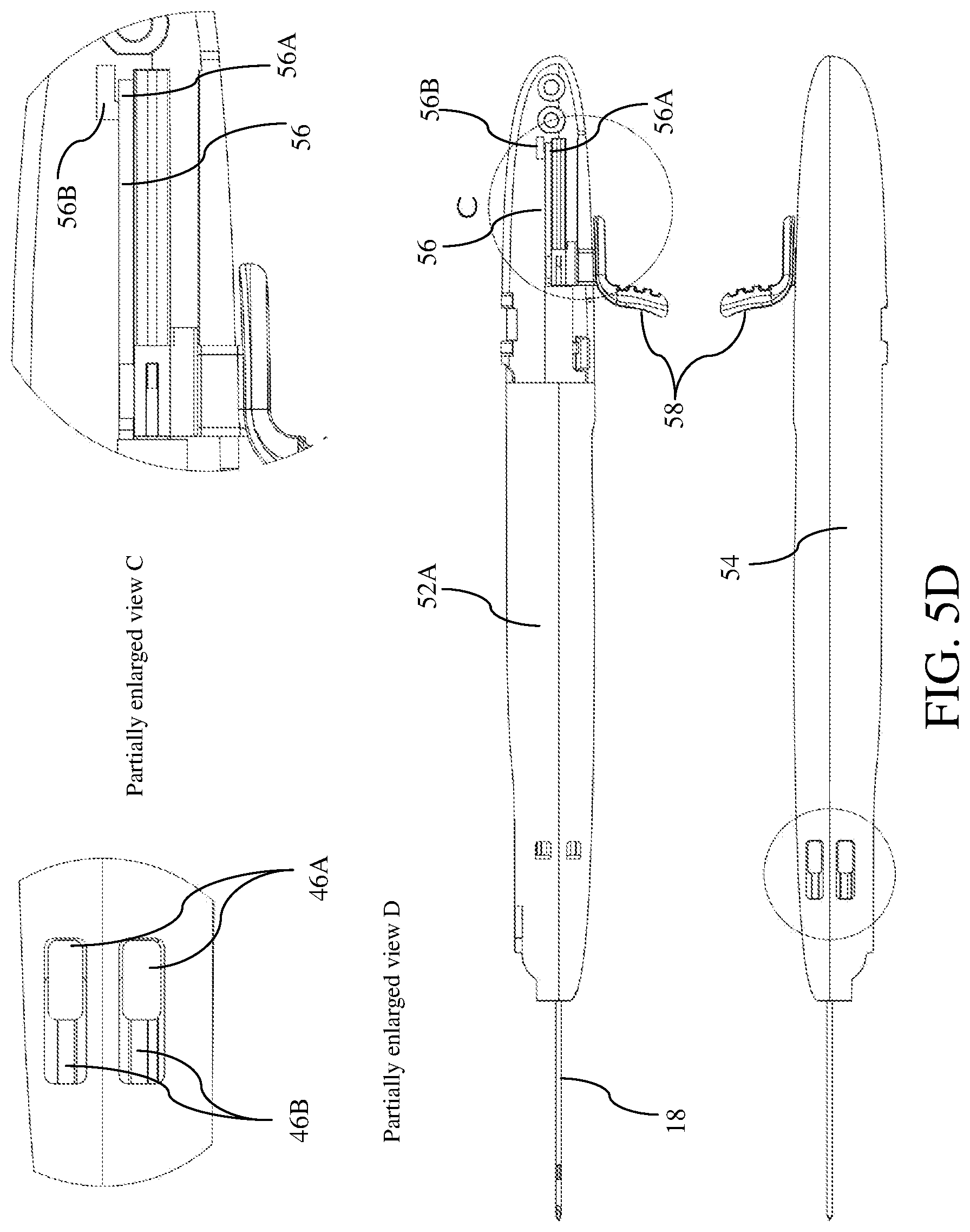
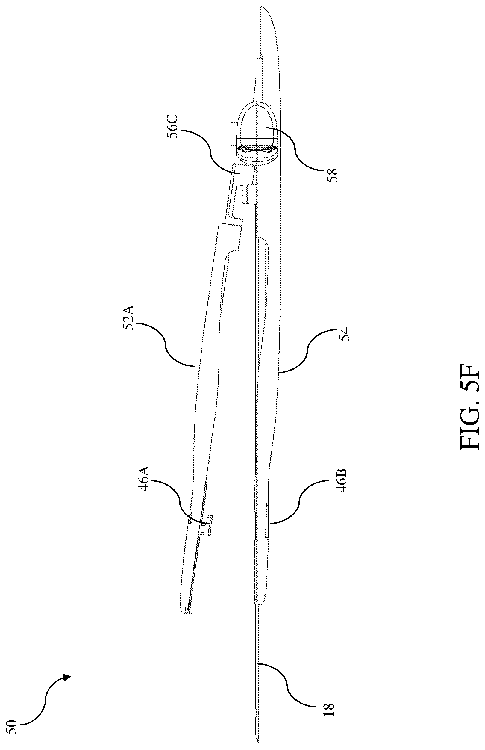
[0024] FIGS. 5D-5F show various views of the housing of FIGS. 5A-5C;
[0025] FIGS. 6A and 6B show various views of the inner structure of the insertion tool according to one embodiment of the present invention;
[0026] FIG. 6C shows the structure of a safety cap of the insertion tool according to one embodiment of the present invention;
[0027] FIGS. 7A and 7B show the engagement between a catheter hub and a safety cap of the insertion tool according to one embodiment of the present invention;
[0028] FIG. 8A is a top view of the cross section of a safety cap and a rail of the insertion tool according to one embodiment of the present invention;
[0029] FIG. 8B is a partially enlarged view of FIG. 8A;
[0030] FIG. 8C is a cross section view of the safety cap of FIGS. 8A and 8B;
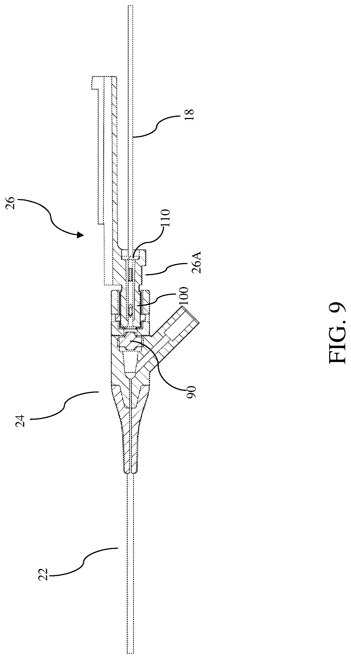
[0031] FIG. 9 shows septa disposed in the insertion tool according to one embodiment of the present invention;
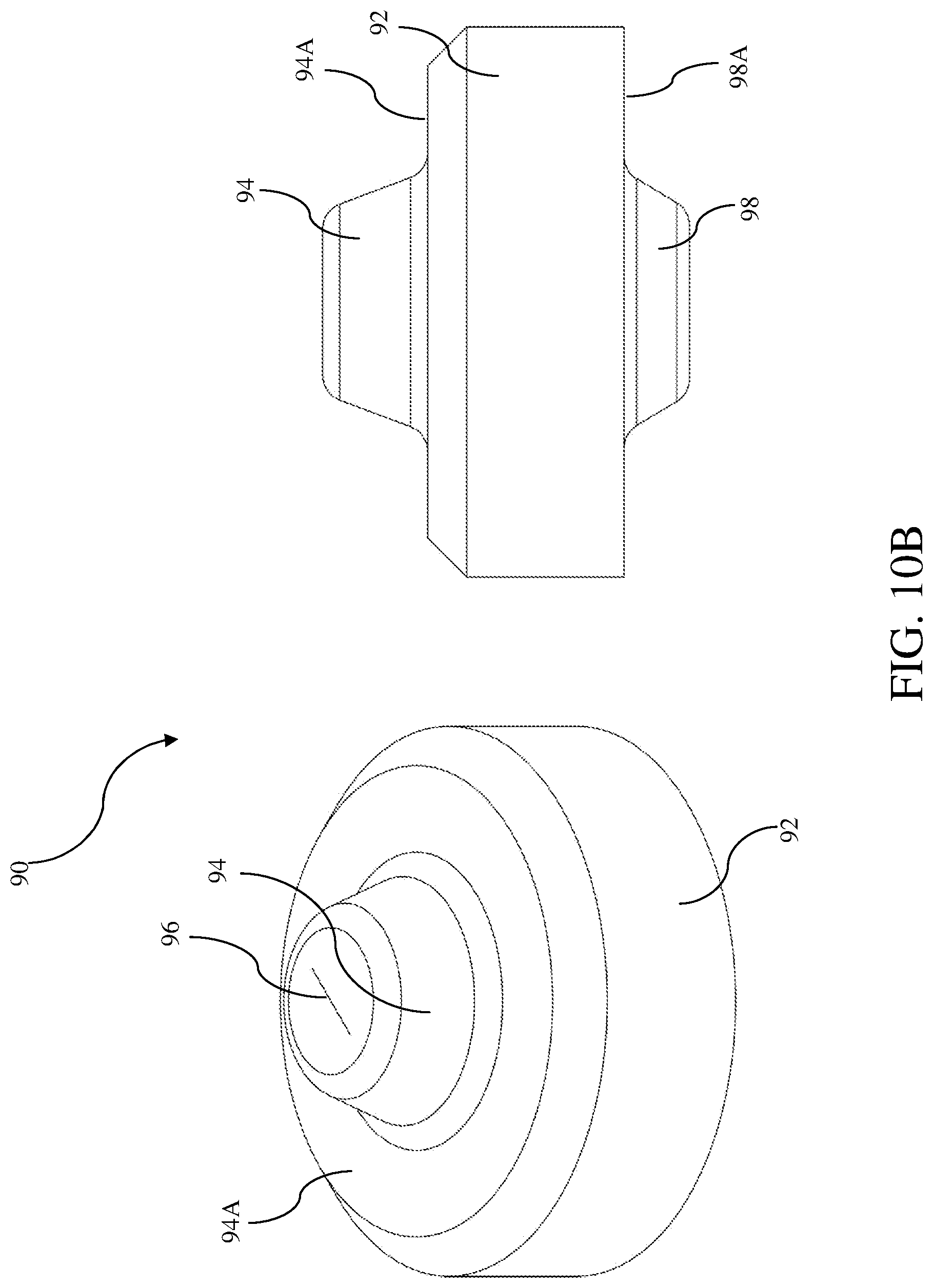
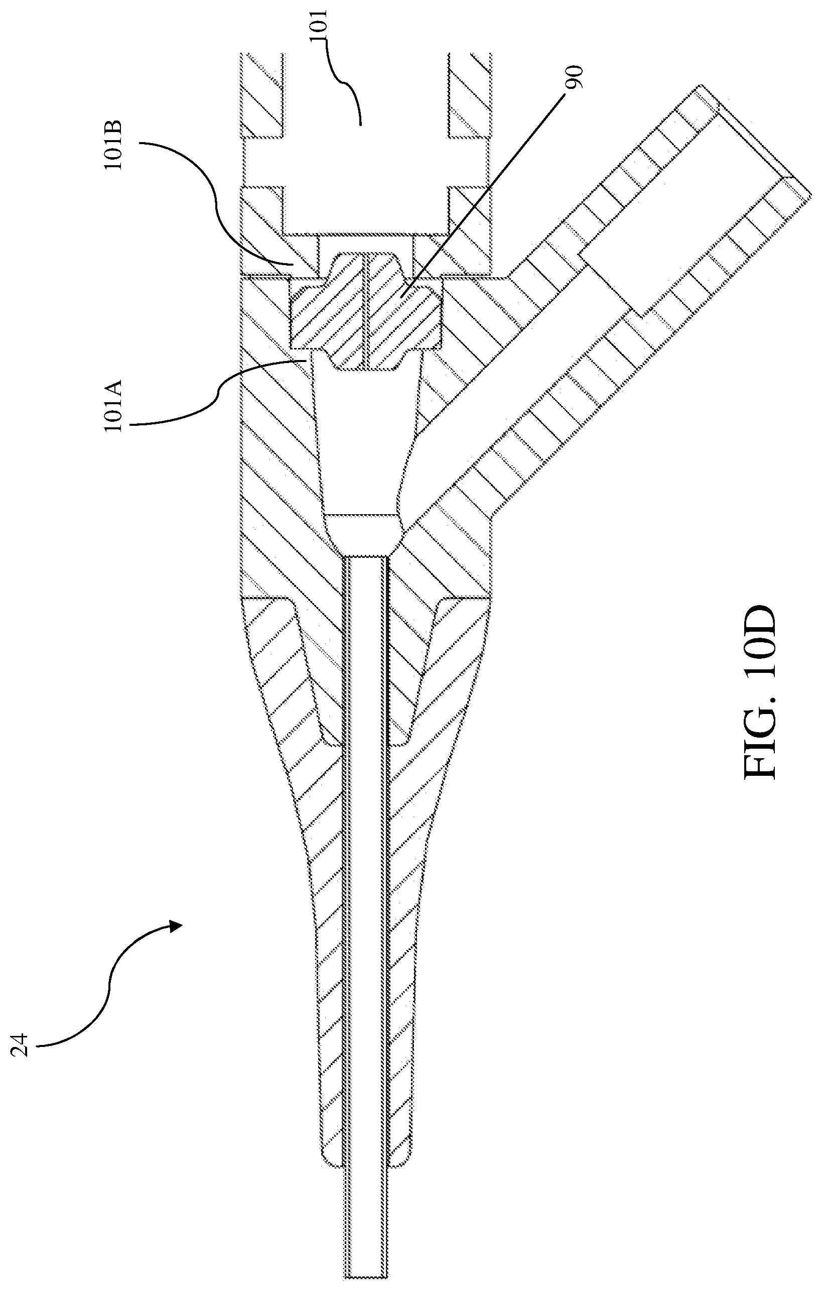
[0032] FIGS. 10A-10D show various views of a septum according to one embodiment of the present invention;
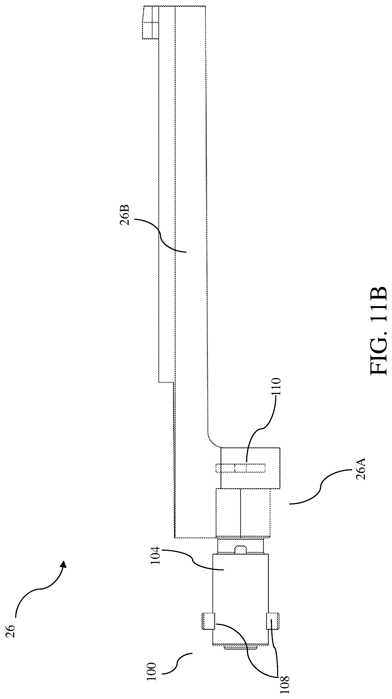
[0033] FIGS. 11A and 11B show various views of a septum according to one embodiment of the present invention;
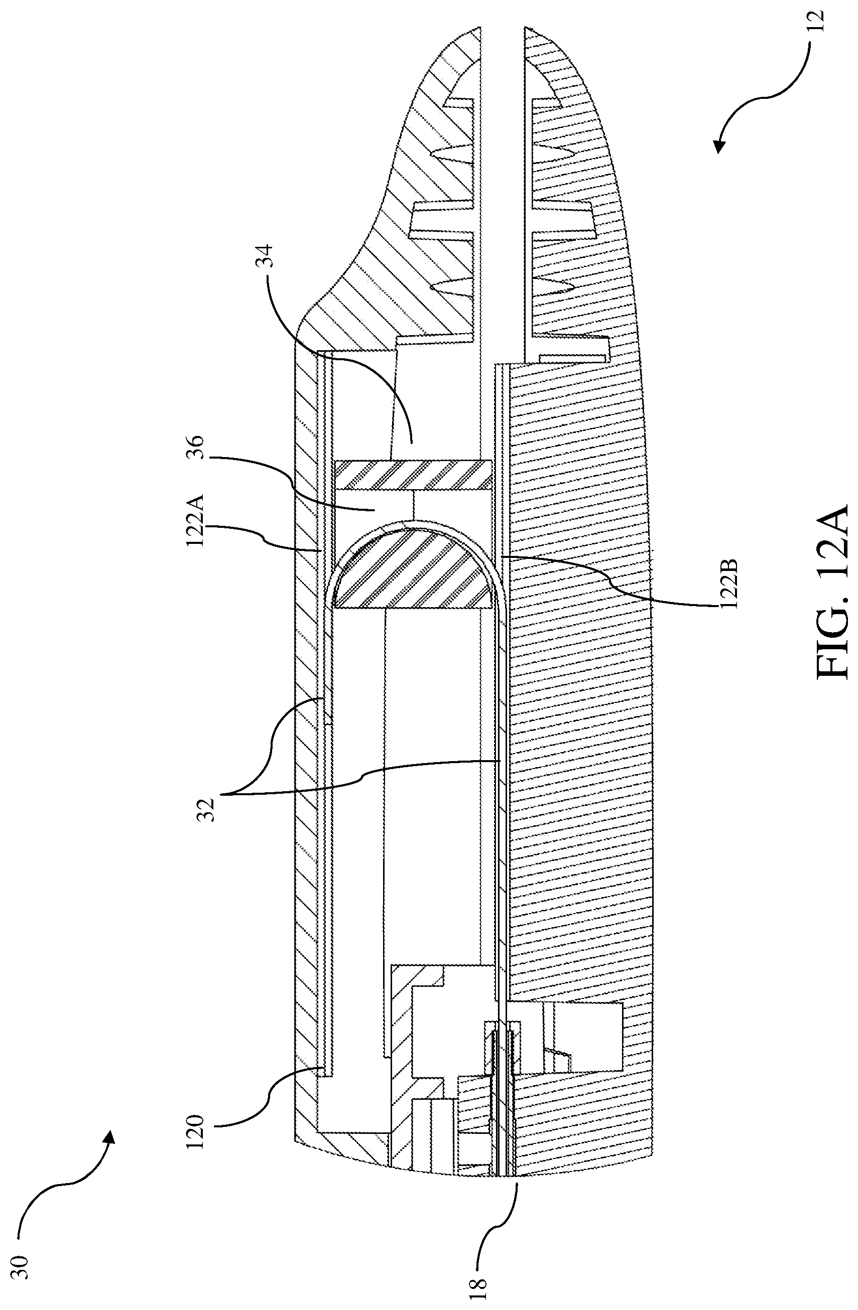
[0034] FIGS. 12A and 12B show various views of a guidewire advancement assembly according to one embodiment of the present invention;
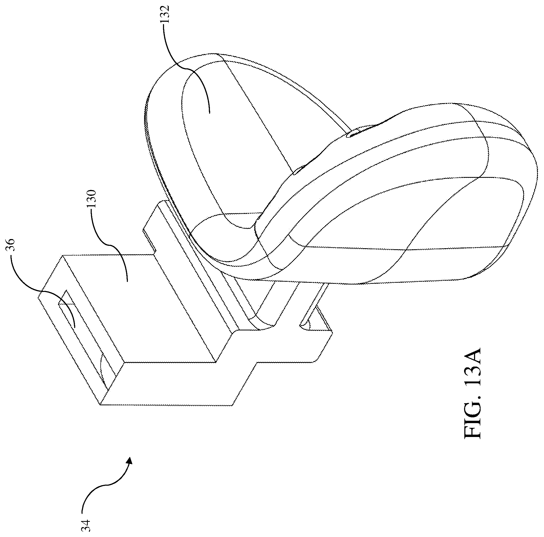
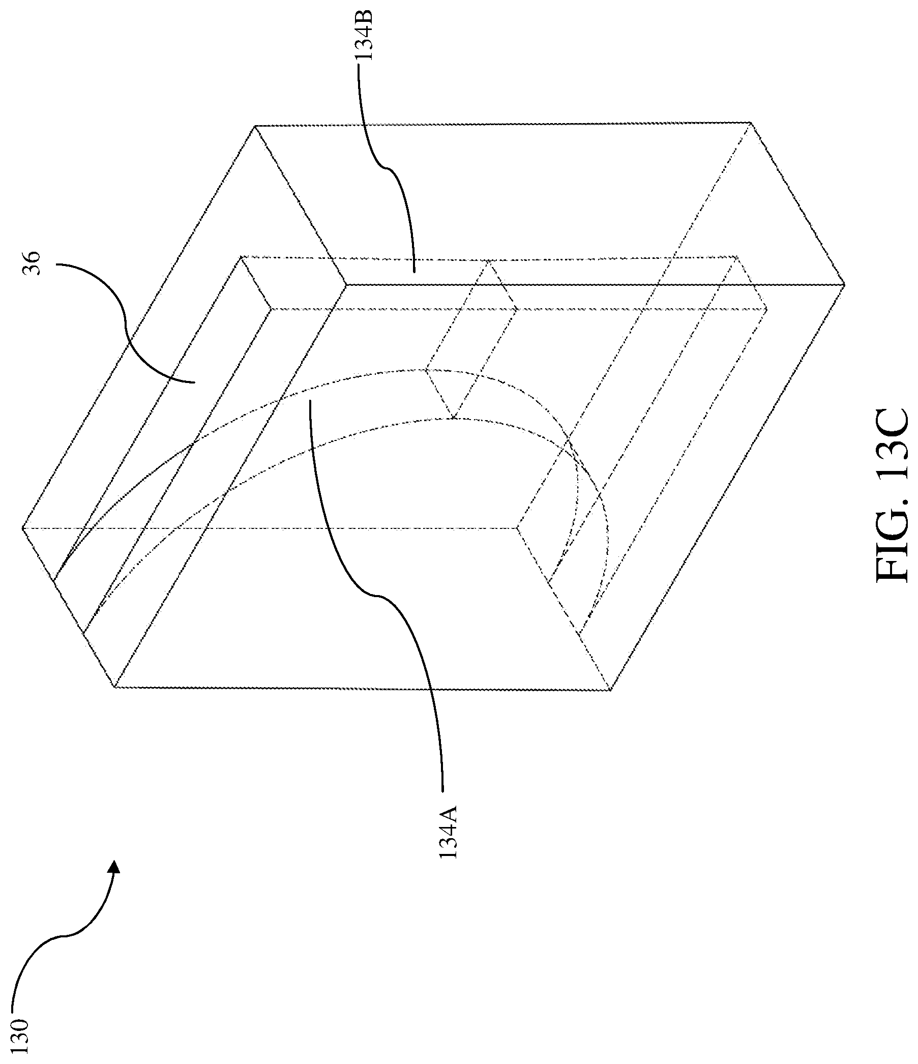
[0035] FIGS. 13A-13C show various views of a guidewire pusher according to one embodiment of the present invention;
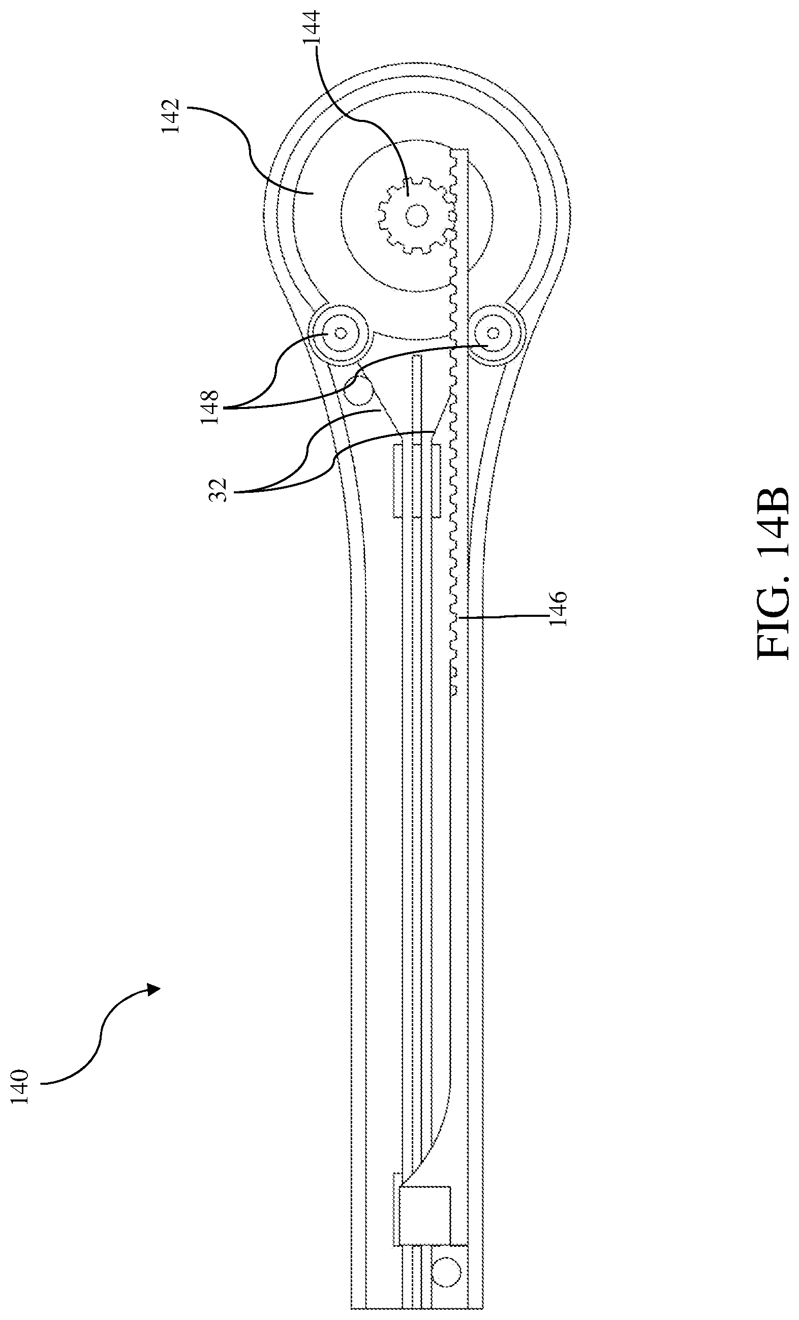
[0036] FIGS. 14A and 14B show various views of a guidewire advancement assembly according to one embodiment of the present invention.
DETAILED DESCRIPTION OF SELECTED EMBODIMENTS
[0037] Reference will now be made to figures wherein like structures will be provided with like reference designations. It is understood that the drawings are diagrammatic and schematic representations of exemplary embodiments of the present invention, and are neither limiting nor necessarily drawn to scale.
[0038] For clarity it is to be understood that the word "proximal" refers to a direction relatively closer to a clinician using the device to be described herein, while the word "distal" refers to a direction relatively further from the clinician. For example, the end of a catheter placed within the body of a patient is considered a distal end of the catheter, while the catheter end remaining outside the body is a proximal end of the catheter. Also, the words "including", "has" and "having" as used herein, including the claims, shall have the same meaning as the word "comprising". Unless specifically indicated otherwise, the word "initially" refers to the state of the insertion tool of the present invention when it is still in the assembled status as delivered to a health-care institution such as a hospital or clinic (or to a patient for use by the patient himself or herself or by the patient's personal care assistant) and has not been operated or used. Unless specifically indicated otherwise, "axial" or "axially" refers to the longitudinal direction of the insertion tool, which is also the orientation of the needle.
[0039] Embodiments of the present invention are generally directed to a tool for assisting with the placement into a patient of a catheter or other tubular medical device. For example, catheters of various lengths are typically placed into a body of a patient so as to establish access to the patient's vasculature and enable the infusion of medicaments or aspiration of body fluids. The catheter insertion tool to be described herein facilitates such catheter placement. Note that, while the discussion below focuses on the placement of catheter of a particular type and relatively shout length, catheters of a variety of types, sizes, and lengths can be inserted via the present device, including peripheral IV's intermediate or extended dwell catheters, PICC's, central venous catheters, etc. In one embodiment, catheters having any length are possible.
[0040] Reference is first made to FIG. 1 and FIG. 2, which depict various details of a catheter insertion tool (also referred to "insertion tool" hereinafter), generally depicted at 10, according to one embodiment. As shown in FIG. 1, which is the perspective view of the insertion tool, the insertion tool 10 includes a housing 12 which in turn includes a first portion 12A and a second portion 12B.
[0041] In one embodiment, the first portion 12A of the housing 12 is separably engaged with a second portion 12B of the housing 12. In one embodiment, the first portion 12A is able to be distally slide with respect to the second portion 12B to release the engagement. Details on the engagement and release will be provided later.
[0042] FIG. 2 is a top view of the cross section of the insertion tool. In one embodiment, as shown in FIG. 2, the insertion tool 10 includes a rail 14 which is integral part of the housing 12 or is an independent element but fixated to the housing 12. For example, the rail 14 can be an integral portion of the first portion 12A (as shown in FIG. 1) of the housing 12 or the second portion 12B of the housing 12, or be fixated to the housing 12 by molding or assembling.
[0043] The insertion tool 10 further includes a handle 16 for a clinician to stably hold the tool 10 while operating the tool. In one embodiment, the handle 16 extends from the rail 14. In other embodiments, the handle 16 extends from the housing 12, wherein the handle is disposed on the first portion 12A or the second portion 12B of the housing 12. In one embodiment, one surface of the handle 16 includes small protrusions in order to increase the friction. In another embodiment, the surface of the handle 16 includes other structures that can increase the friction, for example, grooves, wales, frosted surface and so on. Such protrusions or similar structures on the surfaces of the handle 16 improve the operational stability when the user such as a clinician operates the insertion tool.
[0044] FIG. 3A and FIG. 3B are various exploded views of the insertion tool 10 of FIG. 1 and FIG. 2. Reference now is made to FIG. 3A, where a needle hub 18A supporting a hollow needle 18 is placed between the housing portions 12A and 12B. The needle 18 extends distally form the needle hub 18A, through the body of the insertion tool 10 and out of a distal end of the housing 12. In another embodiment, the needle 18 is at least partially hollow while still enabling the functionality described herein. In one embodiment, a notch 18B is defined through the wall of the needle 18 proximate the distal end thereof. The notch 18B enables flashback of blood to exit the lumen defined by the hollow needle 18 once access to the patient's vasculature is achieved during catheter insertion procedures. Thus, blood exiting the notch 18B can be viewed by a clinician to confirm that the needle is properly inserted into the vasculature.
[0045] As shown in FIGS. 2 and 3B, the insertion tool 10 further includes a catheter advancement assembly 20 for distally advancing a catheter 22 into the vasculature of the patient. The proximal end of the catheter 22 is connected to a catheter hub 24. Both of the catheter 22 and catheter hub 24 are initially disposed on the needle 18. And at least a portion of the catheter 22, and the catheter hub 24, are pre-disposed within the housing 12. In one embodiment, a distal portion of the catheter 22 extends out of the distal end of the housing 12. In one embodiment, the catheter hub 24 includes a handle extending out of the housing 12 from a slot 12C on the housing, and the handle of the catheter hub 24 can be used to effect the advancement of the catheter 22 and the catheter hub 24. The slot 12C exists between the first portion 12A and the second portion 12B of the housing 12, allowing the movement of the handle of the catheter hub 24. In another embodiment, the handle of the catheter hub 24 is a branch pipe 24A extending from the catheter hub 24. In another embodiment, a sterile protection is provided to the branch pipe.
[0046] Reference is continue made to FIGS. 2 and 3B, where the insertion tool 10 includes a safety cap 26. The safety cap 26 is initially attached to the catheter hub 24, and can be separated from the catheter hub 24 when it is distally slid to a certain position. In one embodiment, the safety cap 26 is locked to the housing 12 when sliding to the position. Details on this locking mechanism are to be described below.
[0047] In one embodiment, the safety cap 26 includes a first portion 26A wrapping the needle and a second portion 26B slidably attached to the rail 14. In one embodiment, the position where the catheter hub 24 and the safety cap 26 can be separated is a position where the tip of the needle 18 is isolated within the first portion 26A of the safety cap 26. In one embodiment, the second portion 26B of the safety cap 26 is locked to the rail 14 when the safety cap 26 slides to the position that the tip of the needle 18 is isolated within the first portion 26A of the safety cap 26. The locking between the safety cap 26 (more specifically the second portion 26B) and the rail 14 prevents the relative movement between the safety cap 26 and the needle 18, avoiding the re-exposure of the needle tip and thus eliminating the possibility that the needle pricks the clinician or the patient.
[0048] Referring to FIG. 3B, in one embodiment, the insertion tool 10 further includes at least one septum 28 to prevent blood exposure while the needle and catheter is inserted into or withdrawn from the body of the patient. There can be one or multiple septa placed inside the insertion tool 10. In one embodiment, a septum 28 (not shown in FIG. 3B) is disposed within the lumen of the catheter hub 24. In one embodiment, a septum 28 is disposed on the first portion 26A of the safety cap 26. In one embodiment, a septum 28 is disposed within the lumen of the first portion 26A of the safety cap 26. To be noted, a septum can also be disposed inside another element of the insertion tool, for example, the branch tube of the catheter hub 24. The size and shape of a septum is configured to fit the corresponding element or a lumen of the element, and when multiple septa are used the size and shape of each septa can be the same or different.
[0049] Referring back to FIG. 3A, in one embodiment, the insertion tool 10 comprises a guidewire advancement assembly 30 for distally advancing a guidewire 32 into, or withdrawing it from, the vasculature of the patient. In one embodiment, the guidewire advancement assembly 30 further includes a pusher 34 for operating the movement of the guidewire 32 in preparation for the advancement of the catheter 22.
[0050] In one embodiment, at least a portion of the guidewire 32 is disposed within the lumen of the needle 18. In an alternative embodiment, the distal end of the guidewire 32 is initially dispose within the tip of the needle 18, while the other end of the guidewire 32 is fixated to an anchor point on the housing 12 or the rail 14. The guidewire 32 proximally extends from the anchor point, enters a hole 36 disposed on the pusher 34 and is bended by the hole 36, extends away from the hole 36 and distally extends into the lumen of the needle 18. In one embodiment, the movement of the pusher 34 applies a friction force on the bended portion of the guidewire 32, so as to advance or retract the distal portion of the guidewire 32. When the pusher 34 is distally moved, the guidewire 32 is distally advanced over a distance two times the moving distance of the pusher 34. This conveniently increases the efficiency of guidewire advancement, which is desired in the operation of such a medical device.
Housing
[0051] FIG. 4A and FIG. 4B are side views of a housing 40 of the catheter insertion tool of the present invention. The housing 40 includes a first portion 42 comprising a distal part 42A and a proximal part 42B, and a second portion 44 engaged with the first portion 42, wherein the distal part 42A of the first portion 42 is configured to be able to distally slide with respect to the second portion 44 to release the engagement 46 between the first portion 42 and the second portion 44.
[0052] In one embodiment, the proximal part 42B of the first portion 42 is fixated to the second portion 44. Alternatively, the proximal part 42B of the first portion 42 is engaged with the second portion 44 via a separable configuration, for example a snap-fit joint, pin joint, rivet joint, buckle and so on. A force above a threshold magnitude is required to release the separable engagement between the proximal part 42B of the first portion 42 and the second portion 44, so as to prevent accidental separation of the housing. In another embodiment, the proximal part 42B of the first portion 42 and the second portion 44 are inseparable from each other or form an integrated piece.
[0053] In one embodiment, as shown in FIG. 4C and FIG. 4D, a hook 46A is disposed on an inner surface of the distal part 42A of the first portion 42 of the housing. The hook 46A has a tip extending toward the proximal end of the housing 40. A slot 46B is disposed on the second portion 44. The slot 46B receives the hook 46A when the first portion 42 and the second portion 44 are engaged, and the hook 46A is released from the slot 46B when the distal part 42A of the first portion 42 is slide distally such that the first portion 42 is released from the second portion 44.
[0054] Refers back to FIG. 4A, the first portion 42 and the second portion 44 of the housing 40 are engaged with each other through the engagement 46 formed by the hook 46A and slot 46B and the engagement between the proximal part 42B of the first portion 42 and the second portion 44. In the direction pointed by the arrow, the distal part 42A of the first portion 42 can be distally slid with respect to the second portion 44 of the housing 40. The distal sliding of the distal part 42A of the first portion 42 results in the distal movement of the hook 46A with respect to the hole 46B. When the tip of the hook 46A reaches the position as shown in FIG. 4B, the hook 46A can be separated from the hole 46B, such that the engagement 46 is released and the distal part 42A of the first portion 42 and the second portion 44 can be separated in a perpendicular direction with respect to each other.
[0055] To be noted, while FIGS. 4A-4D only show one pair of hook 46A and hole 46B, in one embodiment, the housing 40 of the present invention includes two hooks and two holes. To better stabilize the engagement 46, as an optimal embodiment, two hooks are arranged in parallel on the inner surface of the distal part 42A and, correspondingly, two holes are arranged on the second portion 44 in the same way as the two hooks. Other numbers and arrangement of the hooks and the holes are possible and within the spirit of the present invention.
[0056] As shown in FIGS. 4A and 4B, in one embodiment, a base 48 is disposed on an inner surface of the second portion 44 of the housing 40 for holding the proximal end of a needle 18. The proximal end of the needle 18 is fixated to the hosing. In one embodiment, the base 48 includes a hole allowing the guidewire to extend into the lumen of the needle 18 via the hole.
[0057] As shown in FIG. 4D, in one embodiment, a groove 45 is disposed on an inner surface of at least one of the first and second portions 42/44, the groove 45 having an inner width which is wide enough to allow free movement of the catheter in an axial direction and narrow enough to restrict the movement of the catheter perpendicular to the axial direction. That is, the first and second portions of the housing when engaged with each other provides supporting for the distal portion of the needle 18 which limits the swing of the needle 18 while the needle 18 is being inserted into or withdrawn from a patient's body.
[0058] In one embodiment, the distal part 42A and the proximal part 42B are always connected to each other before or after the distal movement of the distal part 42A. The connection can be formed by an elastic, or foldable, or hinged connection. Examples of an elastic or foldable connection can be a hinge, spring or another flexible piece.
[0059] In another embodiment, the distal part 42A of the first portion 42 can be separated from the second portion 44 after the distal part is distally slid to release the engagement between the first portion 42 and the second portion 44.
[0060] Continually refer to FIGS. 4A-4D. In another embodiment, the proximal end of the distal part 42A of the first portion 42 includes a structure 49 which is clamped between the proximal part 42B of the first portion 42 and the second portion 44, movement of the structure 49 being limited within a cavity formed by the proximal part 42B of the first portion 42 and the second portion 44. Specifically, in one embodiment, the structure 49 includes a flexible sheet 49A extending proximally from the proximal end of the distal part 42A, and two walls 49B vertically extending from two sides of the end portion of the flexible sheet 49A. In one embodiment, after the distal part 42A is distally slid over a certain distance, the structure 49 is blocked by the base 48 so as to prevent further distal movement of the distal part 42A of the first portion 42. The certain distance is also the distal movement distance of the hook 46A that allows the hook 46A to be released from the hole 46.
[0061] In one embodiment, the sheet 49A and the two walls 49B of the structure 49 of the distal part 42A engage with a ridge extending from the base 48. The ridge acts like a rail for the structure 49, which allows a distal movement along the ridge, but also restricts the swing of the structure 49 during the distal movement.
[0062] In one embodiment, the structure 49 is clamped by the base 48 of the second portion 44 and the inner surface of the proximal part 42B of the first portion 42. This prevents the distal part 42A from being detached from the rest of the housing, and allows the open-close movement of the distal part 42A with respect the second portion 44 with an angle. Such a mechanism avoids the housing form falling apart after use, which is good for medical safety (for example, prevention of needle stick and/or blood contamination) and user experience.
[0063] FIGS. 5A-5C are side views of a housing 50 of the catheter insertion tool of the present invention. As shown in FIG. 5A, the housing 50 includes a first portion 52 comprising a distal part 52A and a proximal part similar to the proximal part 42B shown in FIGS. 4A and 4B, and a second portion 54 engaged with the first portion 52. The proximal end 56 of the distal part 52A of the first portion 52 is configured to be able to be axially locked to the second portion 54, and the distal part 52A of the first portion 52 is configured to be able to distally slide with respect to the second portion 54 when the locking between the proximal end 56 of the distal part 52A of the first portion 52 and the second portion 54 is released, so as to release the engagement 46 between the first portion 52 and the second portion 54.
[0064] Reference continues to be made to FIG. 5A, where in one embodiment, as shown in the partially enlarged view "A", a first protrusion 56A extends from the proximal end 56 of the distal part 52A toward the second portion 54, and a second protrusion 56B extends from the second portion 54 toward the proximal end 56 of the distal part 52A of the first portion 52. In FIG. 5A, the proximal end 56 of the distal part 52A of the first portion 52 is flexible and is biased (by a slider 58 for example) toward the second portion 54, and the first protrusion 56A is proximal relative to the second protrusion 56B, whereby the proximal end 56 of the distal part 52A of the first portion 52 is axially locked to the second portion 54 such that the first portion 52 cannot be axially and distally moved relative to the second portion 54.
[0065] FIG. 5B is the side view of the distal part 52A of the first portion 52 of the housing shown in FIG. 5A. The proximal end 56 of the distal part 52A shown in FIG. 5B is in a natural, unbiased state, and it is in the form of a bevel slightly tilting upwards proximally. The bevel may have a consistent thickness. Alternatively the thickness of the bevel may gradually increase or decrease distally, with the least or greatest thickness reached at the location of the first protrusion 56A (without accounting for the height of the first protrusion 56A itself). The bevel having such a varying thickness may help change the amount of the force the slider 58 imposes on the bevel and the friction between the slider 58 and the bevel.
[0066] FIG. 5C is the side view of the housing 50 when the locking between the proximal end 56 of the distal part 52A of the first portion 52 and the second portion 54 is released. In one embodiment, when the slider 58 is moved distally, the force the slider 58 imposes on the proximal end 56 of the distal part 52A of the first portion 52 decreases and the proximal end 56 is gradually unbiased, and accordingly the first protrusion 56A moves upward relative to the second protrusion 56B. When the slider 58 is distally moved to a certain position as shown in FIG. 5C, the first protrusion 56A moves up to reach a position where the second protrusion 56B no longer blocks the distal movement of the first protrusion 56A and thus the locking between the proximal end 56 of the distal part 52A of the first portion 52 and the second portion 54 is released.
[0067] Similar to the housing 40 in FIGS. 4A-4D, in one embodiment as shown in FIGS. 5D and 5E, a hook 46A is disposed on an inner surface of the distal part 52A of the first portion 52 of the housing 50, and a slot 46B is disposed on the second portion 54 of the housing 50 in a position corresponding to the hook 46A. The hook 46A may be in a form of first perpendicularly protruding from the inner surface of the distal part 52A of the first portion 52 of the housing 50 and then extending horizontally and proximally, as shown in FIG. 5F. The slot 46B receives the hook 46A when the first portion 52 and the second portion 54 are engaged, and the hook 46A is released from the slot 46B when the locking between the proximal end 56 of the distal part 52A of the first portion 52 and the second portion 54 is released and the distal part 52A of the first portion 52 is slide distally, such that the first portion 52 can be released from the second portion 54.
[0068] FIG. 5F is the side view of the insertion tool showing the state when the engagement between the distal part 52A of the first portion 52 and the second portion 54 is released. In one embodiment, the proximal end 56 of the distal part 52A of the first portion 52 includes a structure 56C which is clamped between the proximal part (not shown in FIG. 5F) of the first portion 52 and the second portion 54, and movement of the structure 56C is limited within a cavity formed by the proximal part of the first portion 52 and the second portion 54. Specifically, in one embodiment, the structure 56C is similar to the structure 49 as shown in FIGS. 4A-C. In one embodiment, after the distal part 52A is distally slid over a certain distance, the structure 56C is blocked by the base 48 so as to prevent further distal movement of the distal part 52A of the first portion 52, wherein said certain distance is also the distal movement distance of the hook 46A that allows the hook 46A to be released from the slot 46B.
[0069] Such a locking mechanism between the proximal end 56 of the distal part 52A of the first portion 52 and the second portion 54 can effectively prevent a clinician's inadvertent operation which may cause distal movement of the distal part of the first portion of the housing and thus prevent unwanted separation of the housing. Additionally, in one embodiment, besides releasing the axial locking between the distal part 52A of the first portion 52 and the second portion 54, the distal movement of the slider 58 is also configured to advance the guidewire simultaneously, and such a configuration increases the operational efficiency and safety.
Needle Tip Protection
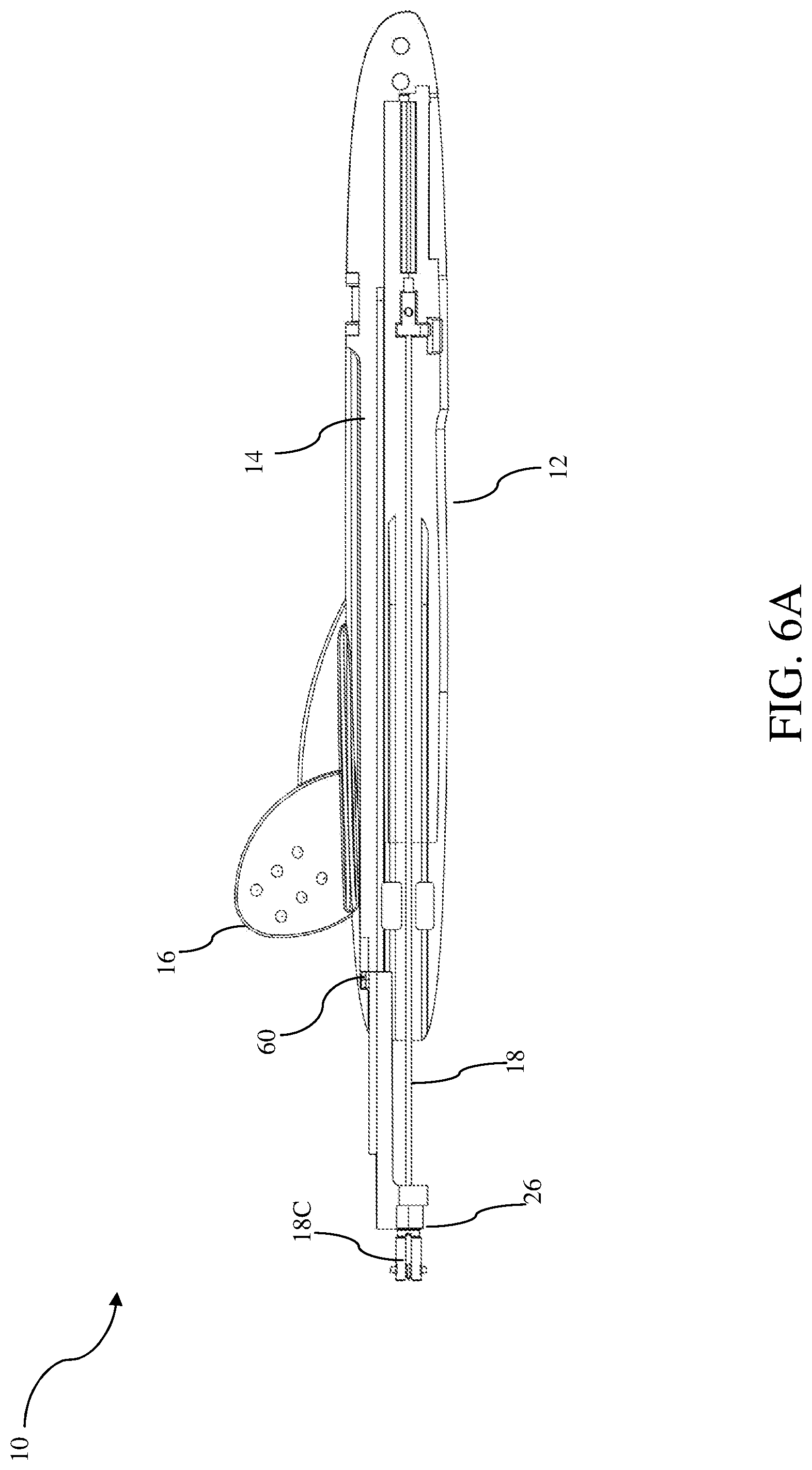
[0070] FIG. 2 and FIG. 6A shows the inner structure of one embodiment of the insertion tool 10 of the present invention. Specifically, FIG. 2 is a top view of the insertion tool 10 without the first portion 12A of the housing 12. In one embodiment, the insertion tool 10 of the present invention includes a housing 12, a rail 14 attached to the housing, a needle 18 distally extending from the housing 12, a catheter advancement assembly 20, a guidewire advancement assembly 30, wherein the catheter advancement assembly 20 includes a catheter 22, a catheter hub 24 and a safety cap 26 which is separably attached to the catheter hub 24.
[0071] Further to the status shown in FIG. 2, FIG. 6A shows the safety cap 26 distally sliding to a position where the safety cap 26 is locked to the rail 14. In one embodiment, the safety cap 26 is configured to be locked to the housing 12 when distally sliding to a position of isolating the tip of the needle 18 within the safety cap 26. To be noted, since the rail 14 can be a part of the housing or is attached to the housing, when the safety cap 26 is locked to the rail 14, the safety cap 26 can also be considered being locked to the housing 12. FIG. 6A clearly shows the position that the safety cap 26 is locked to the housing and the needle tip is isolated within the safety cap 26. At this position, the relevant movement between the safety cap 26 and the needle 18 is restricted, so as to prevent the re-exposure of the needle tip.
[0072] FIG. 6B shows the view that the catheter hub 24 is separated from the safety cap 26 when the safety cap 26 is at the position as described in FIG. 6A.
[0073] As shown in FIGS. 6A and 6B, in one embodiment, the safety cap 26 is locked to the housing 12 at a location 60 and the tip 18C of the needle 18 is isolated within the safety cap 26 when the safety cap 26 slides to the position of isolating the tip 18C of the needle within the safety cap.
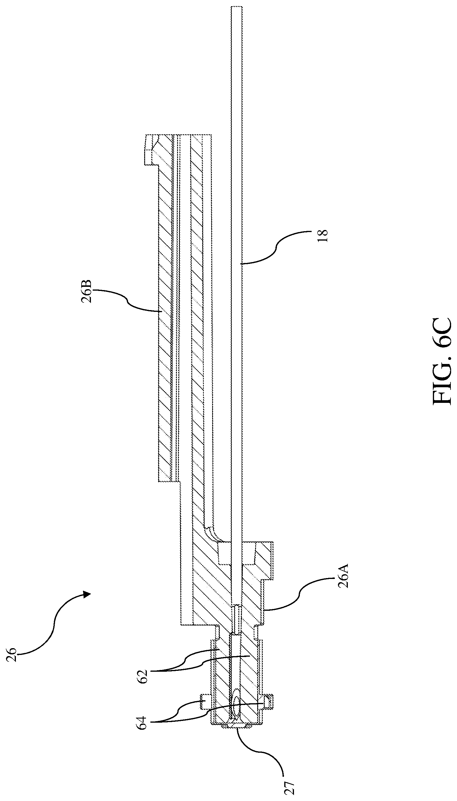
[0074] FIG. 6C shows the structure of the safety cap 26 of one embodiment of the present invention. The safety cap 26 includes a first portion 26A and a second portion 26B. Viewed in combination with FIGS. 2, 6A and 6B, in one embodiment, the first portion 26A of the safety cap 26 wraps the needle 18 and the second portion 26B of the safety cap 26 is slidably attached to a rail 14. Specifically, in one embodiment, the first portion 26A of the safety cap 26 includes a lumen 27 extending through the first portion 26A which contains and wraps the needle 18.
[0075] In one embodiment, the first portion 26A of the safety cap 26 has two fingers 62. In one embodiment, the two fingers 62 have a slit between them which wraps the needle 18. In another embodiment, three, four or even more fingers are possible. In another embodiment, the fingers 62 are in the shape of a strip or column.
[0076] FIGS. 7A and 7B shows the engagement between the catheter hub 24 and the safety cap 26 of one embodiment of the present invention. The engagement is formed by inserting a protrusion 64 on the fingers 62 into a recess 66 disposed on the catheter hub 24.
[0077] Referring to FIG. 7A, in one embodiment, the fingers 62 are configured to be biased radially toward an inner surface of the catheter hub 24 when the stem of the needle 18 extends through the first portion 26A of the safety cap 26. That is, when the first portion 26A of the safety cap 26 wraps the needle stem, the fingers 62 are slightly biased/pressed outward by the needle 18. The radially biased fingers 62 insert their protrusion 64 into the recess 66, and the pressure from the needle 18 helps secure the insertion of the protrusion 64 into the recess 66, thus realizing the engagement between the catheter hub 24 and the safety cap 26.
[0078] Referring to FIG. 7B, in one embodiment, the fingers 62 are configured to be released from the biased position when the safety cap 24 distally slides to the position of isolating the tip of the needle 18. That is, when losing the pressure from the needle, the fingers 62 converge towards the axis of lumen of the catheter hub 24, and the protrusion 64 can be pulled out of the recess 66 and thus the catheter hub 24 can be separated from the safety cap 26.
[0079] Referring to FIG. 7A, in one embodiment, the fingers 62 are configured to remain in the same position when the stem of the needle extends through the first portion 26A of the safety cap 26 and when the safety cap 26 distally slides to the position of isolating the tip of the needle. That is, the fingers 62 are kept at the same position and basically are not biased with or without the pressure from the needle 18. And the outer diameter of the hollow cylinder formed by the fingers do not change whether the needle extends through the hollow cylinder or not. Nonetheless, the pressure from the needle 18 facilitates the insertion between the protrusion 64 and the recess 66.
[0080] Referring to FIG. 7B, in one embodiment, when losing the pressure from the needle, the fingers 62 are kept at the same position as biased/pressed by the needle 18. In this situation, when a user of the insertion tool tries to pull the safety cap 26 away from the catheter hub 24, the protrusion 64 is pulled out of the recess 66.
[0081] In one embodiment, each of the fingers 62 includes a protrusion 64, and a corresponding number of recesses 66 are disposed on the inner surface of the catheter hub. In one embodiment, each of the fingers 62 can include one or more protrusions 64.
[0082] Reference is now made to FIG. 6C. The proximal side of the protrusion 64 forms an obtuse angle relative to the surface of the finger 62 where the proximal side extends from the finger 62. That is, the proximal side of the protrusion 64 is a slope which allows the protrusion 64 to be pulled out from the recess 66 when the fingers 62 are not biased/pressed by the needle 18.
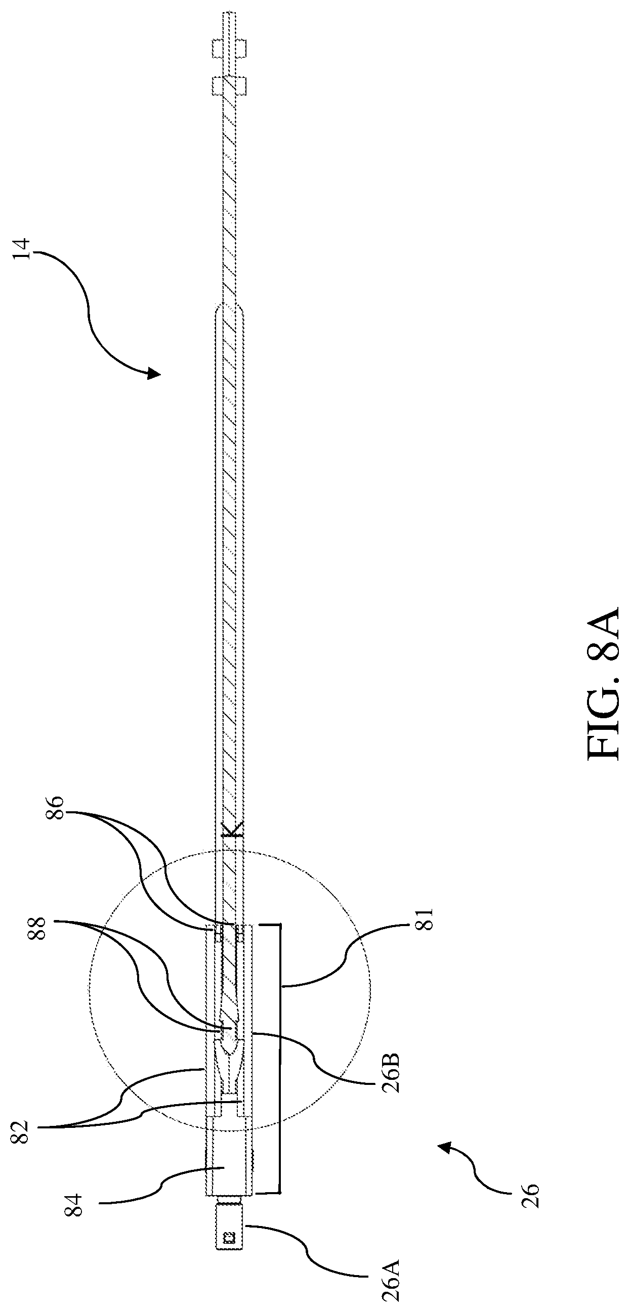
[0083] Referring to FIGS. 8A-C, the second portion 26B of the safety cap 26 is a lever 81, which slides along the rail 14. In one embodiment, the lever 81 includes two vertical walls 82 vertically extending from the two sides of a surface 84 of the lever 81 facing the rail 14. Each of the two vertical walls 82 has a horizontal part with a protrusion 86, which protrusion is locked within a notch 88 formed on the rail 14 so as to lock the safety cap 26 to the housing 12 when the safety cap 26 distally slides to the position of isolating the tip of the needle 18 within the safety cap 26.
[0084] To clearly depict the structure of the lever 81, reference is made to FIG. 8C, which is a sectional view of a plane perpendicular to the axis of the lumen of the safety cap 26. In one embodiment, the surface 84 of the lever facing the rail 14 includes two vertical walls 82, and the lever 81 is connected to the first portion 26A of the safety cap 26 on the opposite side of the surface 84. Each of the two vertical walls 82 has a horizontal part with a protrusion 86. Here the horizontal part is basically parallel to the surface 84, and in one embodiment, the vertical walls 82 extends throughout the full length of the lever, and the horizontal part is shorter than the full length of the lever. In another embodiment, the vertical walls 82 extend over only a partial length of the lever, and the horizontal part is shorter than the length of the vertical walls 82.
[0085] As shown in FIG. 8B, in one embodiment, the notch 88 is formed between two prominent bumps 88A and 88B disposed on the rail. In another embodiment, the proximal bump 88A has an inclined slope 88C at the proximal side and is substantially vertical to the surface of the rail at the distal side. In one embodiment, the distal bump 88B is raised higher from the surface of the rail 14 than the proximal bump 88A. While the protrusions 86 slide over the inclined slope 88C of the proximal bump 88A, the distance between the two protrusions 86 of the lever increases along the inclined slope 88C and the tension between the two protrusions 86 also gradually increases. When the protrusions 86 fall into the notch formed by the prominent bumps 88A and 88B, further movement of the protrusions 86 is blocked by the proximal side of the prominent bump 88B and distal side of the prominent bump 88A, and thus the safety cap 26 is locked to the rail 14.
[0086] In one embodiment, a user of the insertion tool (e.g. a clinician) feels a tactile sensation when the safety cap 26 is locked to the housing 12, for example when the protrusions 86 of the lever fall into the notch 88. In one embodiment, an audible sound is produced besides the tactile sensation.
Septum
[0087] Referring to FIG. 9, in one embodiment, the insertion tool includes at least one septum 90 to prevent blood exposure while the needle is inserted and the catheter is advanced into or away from the body of the patient. In one embodiment, the septum 90 can be disposed in a lumen within the insertion tool. For example, the septum 90 can be placed in a lumen of the catheter hub 24 of the insertion tool, and/or can be placed in a lumen of the safety cap 26 of the insertion tool.
[0088] In one embodiment, a septum 90 is disposed within the lumen of the catheter hub 24. In one embodiment, a septum 100 is disposed in the first portion 26A of the safety cap 26. In one embodiment, a septum 110 is disposed within the lumen of the first portion 26A of the safety cap 26. To be noticed, the septum can also be disposed in other element of the insertion tool, for example, the branch tube of the catheter hub 24. The size and shape of the septum 26 is configured to fit the corresponding element or lumen of the element, and the size and shape of each septa can be the same or different.
[0089] FIGS. 10A-D shows a septum 90 of one embodiment of the present invention. Referring to FIG. 10A, in one embodiment, the septum 90 comprises a cylindrical main body 92, and a first protrusion 94 which extends from a central portion of a top surface 94A of the main body 92. In one embodiment, the thickness of the cylindrical main body 92 is configured to be smaller than the distance between the tip and the notch of the needle 18, so as to reduce the friction between the septum 90 and the needle 18.
[0090] As shown in FIG. 10B, the septum 90 has a slit 96 formed within the septum 90 along the longitudinal axis of the septum. In one embodiment, the slit 96 is formed within the first protrusion. In one embodiment, the slit 96 extends through the septum. Specifically, the slit 96 can extend partially or entirely through the cylindrical main body 92 and the protrusion. In one embodiment, the slit 96 is enlarged when a needle 18 extends through it and is closed when the needle 18 is withdrawn from the septum 90. When the needle punctures the entire septum, the slit 96 consequentially extends throughout the septum. As a preferred embodiment, to ensure the sealing performance of the septum 90, the slit 96 initially is not through the entire thickness of the septum 90, and thus when the needle punctures the septum 90 during the assembling process, the septum 90 will tightly wrap the needle and provide a tight seal around the needle. As another embodiment, the septum 90 is formed without a through slit, and when the needle punctures the septum 90, the septum 90 tightly wraps the needle and may provide a tighter seal around the needle than a configuration with a slit does (assuming the configuration is the same in all the other aspects).
[0091] In one embodiment, the outer diameter of the main body 92 of the septum 90 is slightly larger than the inner diameter of the lumen of the catheter insertion tool before the septum 90 is installed in the lumen. Specifically, the outer diameter of the main body 92 of the septum 90 is larger than the inner diameter of the catheter hub 24. When the septum 90 is assembled in the lumen of the catheter hub 24, the inner surface of the catheter hub 24 is in tight contact with the septum 90 and thus provides better sealing.
[0092] In one embodiment, the first protrusion 94 of the septum is in the form of a circular truncated cone tapering from the top surface 94A of the main body 92 as shown in FIG. 10B. And the circular truncated cone is coaxial with the main body 92. In one embodiment, the first protrusion 94 is integral with the main body 92.
[0093] In one embodiment, the top surface 94A of the septum 90 is rounded at the peripheral. In one embodiment, the top surface of the circular truncated cone is rounded at the peripheral.
[0094] In one embodiment, the septum 90 of the present invention further includes a second protrusion 98 which extends from a central portion of the bottom surface 98A of the main body 92 opposite to the top surface 94A.
[0095] In one embodiment, the second protrusion 98 is in the form of a circular truncated cone tapering from the bottom surface 98A as shown in FIGS. 9A and 9B. And the circular truncated cone is coaxial with the main body 92. In one embodiment, the second protrusion 98 is integral with the main body 92 and forms an integrated body. In another embodiment, the second protrusion 98 is in the form of a cylinder embedded in the central of the main body 92. In another embodiment, the first protrusion 94 and the second protrusion 98 forms a cylinder embedded in the central of the main body 92. In one embodiment, the slit 96 partially extends in the cylinder formed by the first protrusion 94 or the second protrusion 98. In another embodiment, the slit 96 extends throughout the cylinder.
[0096] In one embodiment, the first and the second protrusion are the same in size and shape. In another embodiment, the second protrusion 98 is lower than the first protrusion 94. When the lumen of the catheter hub 24 is full of fluid (e.g. blood) at a side of the septum 90, the side surface of the first or the second protrusion facing the fluid assumes the centripetal pressure from the fluid and wraps the needle more tightly when a needle extends through the septum or shuts the slit more tightly if a slit has been formed through the septum, thus providing better fluid sealing.
[0097] FIGS. 10C and 10D show a septum 90 assembled in the catheter hub 24. In one embodiment, as shown in FIG. 10C the septum 90 is disposed at the distal end of a lumen 101 of the catheter hub 24, which lumen is to accept the safety cap 26. The lumen 101 has a step 101A where the inner diameter of the lumen 101 drops distally. Proximal to the step 101A, the outer diameter of the main body 92 of the septum 90 is big enough to provide a fluid-sealing contact with the inner surface of the lumen 101 of the catheter hub 24. Distal to the step 101A, the first protrusion 94 of the septum 90 extends into the lumen 101 distal to the step 101A. To be understood, the septum can also be disposed in other positions within the lumen 101 of the catheter hub 24. In another embodiment as shown in FIG. 10D, the septum 90 is sandwiched between two steps 101A and 101B formed in the inner surface of the lumen 101 of the catheter hub 24.
[0098] In one embodiment, the septum 90 is made of polyisoprene, silicone rubber, polyurethane, butyl rubber or latex.
[0099] FIGS. 11A and 11B show a septum 100 of one embodiment of the present invention. Referring to FIG. 11A, in one embodiment, the septum 100 comprises a circular end portion 102 and a tubular portion 104 extending from the peripheral of the end portion 102. In one embodiment, the septum 100 is in the shape of a tubular with a close end (circular end portion 102) at the distal end of the septum 100 and an open end at the proximal end of the septum 100. Specifically, in one embodiment, the end portion 102 is a rounded thin film, and the tubular portion 104 extends from the perimeter of the film in a direction perpendicular to the plane of the end portion 102.
[0100] In one embodiment, the septum 100 further includes a protrusion 106 extending from a central portion of a surface of the circular end portion 102 opposite to the tubular portion 104. In one embodiment, the protrusion 106 is in the form of a cylinder. In another embodiment, the protrusion 106 is in the form of a circular truncated cone tapering from the bottom surface. The protrusion 106 is coaxial with the circular end portion 102. In one embodiment, the protrusion 106, the circular end portion 102 and the tubular portion 104 form an integral piece.
[0101] Similar to the septum 90, the end portion 102 of the septum 100 can be formed with or without a slit.
[0102] FIG. 11B shows the septum 100 assembled on the distal portion of the safety cap 26. In one embodiment, the septum 100 is disposed on the fingers of the safety cap 26, wherein the sidewall of the tubular portion 104 includes at least one recess 108 which allows the protrusions disposed on the fingers to extend through the recess 108. In one embodiment, the number and position of the recesses 108 disposed on the tubular portion 104 correspond to the number and position of the protrusion disposed on the fingers of the safety cap 26. As mentioned above, the fingers of the safety cap are separated from each other in the distal portion of the fingers, and are configured to be biased radially when wrapping the needle and to be converged centrally when the needle is pulled out therefrom. The septum 100 is configured to cap/cover the fingers so as to provide a sealing to prevent blood from leaking from the fingers of the safety cap.
[0103] Moreover, when the fingers 62 of the safety cap 26 are fully or partially inside the lumen 101 of the catheter hub 24, for example as shown in FIG. 7B, 9 or 10D, the septum 100 disposed on the fingers 62 enhances the sealing between the safety cap 26 and the catheter hub 24. And the septum 100 provides an appropriate friction between the safety cap 26 and the catheter hub 24, and the friction requires the user/clinician to apply a force to separate the catheter hub 24 and the safety cap 26 when the safety cap 26 slides to a locking position that the needle tip is isolated within the safety cap.
[0104] In addition, as another embodiment, the septum 100 disposed on the fingers of the safety cap 26 and the septum 90 disposed in the lumen 101of the catheter hub 24 contacts each other when the safety cap 26 and the catheter hub 24 are connected. Specifically, in one embodiment, the main body 92 or protrusion 94/98 of the septum 90 is in tight contact with the protrusion 106 or end portion 102 of the septum 100 when the finger portion of the safety cap 26 is fully inserted into the lumen 101 of the catheter hub 24. Such a configuration can prevent blood leaking while the needle tip passes through the septa 90 and 100, and accordingly prevent blood exposure when the safety cap 26 and the catheter hub 24 are separated from each other.
[0105] In one embodiment, the septum 100 is made of polyisoprene, silicone rubber, polyurethane, butyl rubber or latex.
[0106] In one embodiment, as shown in FIG. 11B, the catheter insertion tool 10 further includes a septum 110 disposed in the lumen of the first portion 26A. Specifically, as an embodiment, the septum 110 is in the shape of a cylinder. In one embodiment, the thickness of the septum 110 is configured to be smaller than the distance between the tip and the notch of the needle 18, so as to reduce friction between the septum 110 and the needle 18.
[0107] Similar to the septum 90, septum 110 can be formed with or without a slit.
[0108] In one embodiment, the outer diameter of the septum 110 is larger than the inner diameter of the lumen of the first portion 26A of the safety cap 26 before the septum 110 is installed in the lumen.
[0109] In one embodiment, the septum 110 is disposed in the proximal end of the lumen of the first portion 26A, so as to form a closed cavity together with the septum 100 and the lumen 101. Accordingly, the closed cavity prevents blood from leaking when the needle tip is isolated within the closed cavity of the safety cap 26.
[0110] In one embodiment, the septum 110 is made of polyisoprene, silicone rubber, polyurethane, butyl rubber or latex.
Guidewire Advancement Assembly
[0111] Referring back to FIG. 2 or FIG. 3A, in one embodiment, the insertion tool 10 comprises a guidewire advancement assembly 30 for distally advancing a guidewire 32 into the vasculature of the patient or proximally withdrawing the guidewire from the vasculature of the patient. In one embodiment, the guidewire advancement assembly 30 further includes a pusher 34 for operating movement of the guidewire 32 in preparation for the advancement of the catheter 22.
[0112] FIGS. 12A and 12B show the sectional view of the guidewire advancement assembly 30 before and after advancing the guidewire 32. In one embodiment, at least a portion of the guidewire 32 is disposed within the lumen of the needle 18. One end of the guidewire 32 is fixated to an anchor point 120 on the housing 12, and the guidewire 32 proximally extends from the anchor point 120, enters a hole 36 of the pusher 34 via a first potion of the rail 122A, extends away from the hole 36, distally extends into a second portion of the rail 122B, and finally extends into the lumen of the needle 18 through the needle base.
[0113] In one embodiment, the rail 122A-B includes a groove aligned with the hole 36 in the longitudinal direction of the catheter insertion tool. The groove serves to restrict the guidewire 32 and prevents unwanted waggle or bending of the guidewire 32 during operation. Specifically, as an embodiment, the anchor point 120 and the first portion of the rail 122A is disposed on an inner surface of the first portion 12A of the housing 12. The anchor point 120, the first portion of the rail 122A and the upper opening of the hole 36 of the pusher 34 are arranged in a line, which allows the guidewire 32 to straightly extend from the anchor point 120 to the hole 36. The second portion of the rail 122B is disposed on an inner surface of the second portion 12B of the housing 12. The bottom opening of the hole 36, the second portion of the rail 122B and the proximal end of the needle 18 are arranged in a line, which allows the guidewire 32 to straightly extend from the hole 36 into the lumen of the needle 18. In another embodiment, at least a part of the rail 122A-B is a pipe.
[0114] FIG. 12A shows the configuration of the guidewire advancement assembly 30 before operation, where the pusher 34 is positioned close to the proximal end of the housing. When the pusher 34 is distally moved to a position close to the needle base as shown in FIG. 12B, the guidewire 32 is distally advanced over a distance two times the moving distance of the pusher 34.
[0115] FIGS. 13A-13C shows the structure of pusher 34. FIG. 13A is a perspective view of one embodiment of the pusher 34, where the pusher 34 includes a pushing block 130 and a slider 132. In one embodiment, the pushing block 130 includes a hole 36 extending through the pushing block 130 from a top surface to a bottom surface of the pushing block 130.
[0116] FIG. 13B is a sectional view of the pushing block 130, and FIG. 13C is a perspective view of the pushing block 130. As shown in FIGS. 13B and 13C, the pushing block 130 includes four sidewalls defining the hole 36. In one embodiment, the four sidewalls of the hole 36 includes a first sidewall 134A in the form of a planar curve, and a straight second sidewall 134B opposite to the first sidewall. The minimum distance between the first and second sidewalls 134A and 134B is wide enough to allow free longitudinal movement of a guidewire 32 and is narrow enough to restrict sway of the guidewire 32. In another embodiment, the second sidewall 134B is also in the form of a planar curve, wherein the planar surface of the second sidewall 134B is in parallel to the planar surface of the first sidewall 134A. In one embodiment, the other two sidewalls are straight.
[0117] Referring back to FIG. 2 and FIG. 13A, in one embodiment, the slider 132 is connected to the pushing block 130, the pushing block 130 is disposed inside the housing 12 and the slider 132 is partially disposed outside the housing 12. In one embodiment, a slit is formed between the second portion 13B of the housing and the proximal portion of the first portion 13A of the housing, which clamps the connection part between the pushing block 130 and the slider 132, and allows the pusher 34 slide with respect to the housing 12.
[0118] FIGS. 14A and 14B show another embodiment of the guidewire advancement assembly 140 of the present invention. In one embodiment, the guidewire advancement assembly 140 includes a wheel 142 and a gear 144, wherein the gear 144 is fixated to the wheel 142 coaxially. The rotation of the gear 144 synchronously drives the rotation of the wheel 142. In one embodiment, a guidewire 32 is partially rolled around the outer diameter of the wheel 142.
[0119] In one embodiment, the guidewire advancement assembly 140 further includes a rack 146, which engage with the gear 144 through the engagement between the teeth of the rack 146 and the teeth of the gear 144. In one embodiment, a distal end of the rack 146 is slidably attached to a rail disposed on the housing. The sliding movement of the rack 146 along the rail drives the rotation of the gear 144 and the rotation of the wheel 142, and the guidewire 32 is accordingly driven around the wheel 142.
[0120] In one embodiment, the guidewire advancement assembly 140 further includes at least one idler 148 for restricting the guidewire 32 against the peripheral surface of the wheel 142. In one embodiment, at least the peripheral surface of the wheel 142 is configured to provide sufficient friction for preventing skid between the wheel 142 and the guidewire 32. This can be done by way of special treatment of the peripheral surface or by selecting a proper material to form the surface.
[0121] In one embodiment, the guidewire advancement assembly 140 further includes a pipe rail for guiding the movement of the guidewire 32.
[0122] The advancement efficiency of the guidewire advancement assembly 140 depends on the ratio between the diameter of the gear 144 and the wheel 142. For example, if the ratio between the diameter of the gear 144 and the wheel 142 is 1:3, the ratio between the sliding distance of the rack 146 and the moving distance of the guidewire is also 1:3.
Operation Procedures
[0123] FIGS. 4A-5C depict various stage of the operation of the insertion tool 10 to place the catheter 22 into the vasculature of a patient. For clarity, the various stages are depicted without actual insertion into a patient being shown. With the insertion tool 10 in the configuration shown on FIG. 2, a user grasping the insertion tool 10 first guides the distal portion needle 18 through the patient's skin at a suitable insertion site and accesses a subcutaneous vessel. Confirmation of proper vessel access having been achieved is evident via blood flash, i.e., the presence of blood between the outer diameter of the needle 18 and the inner diameter of the catheter 22 due to blood passing out of the notch from the hollow interior of the needle. Note that in one embodiment, the presence of blood in the safety cap 26 serves as a secondary blood flash indicator due to blood entering the housing from the needle 18 when the vessel is accessed.
[0124] After needle access to the vessel is confirmed, the user operates the guidewire advancement assembly 30 or 140. In one embodiment, as to the guidewire advancement assembly 30 shown in FIGS. 12A-13C, the pusher 34 is distally slid by the finger of the user to distally advance the guidewire 32, which is initially disposed within the hollow needle 18. In another embodiment, as to the guidewire advancement assembly 140 shown in FIGS. 14A-14B, the rack 146 is distally slid by the finger of the user to distally advance the guidewire 32. The distal advancement of the guidewire continues until the pusher 34 has been distally slid its full travel length, resulting in a predetermined length of the guidewire 32 extending past the distal end of the needle 18. In one embodiment, further distal advancement of the pusher 34 is prevented when the pushing block 130 contacts the needle base.
[0125] Once the guidewire 32 has been fully extended within the vessel of the patient, the user operates the catheter advancement assembly 20, wherein the catheter hub 24 is distally advanced by the user to cause the catheter 22 to slide distally over the needle 18 and the guidewire 32 and into the patient's vasculature via the insertion site. At this stage, further distal movement of the catheter hub and the catheter is prevented by the distal portion of the housing. The user then may slide the distal part of the first portion of the housing with respect to the second portion of the housing to release the engagement between the two housing portions. After the release, further distal movement of the catheter hub and the catheter is allowed. To be noted, during the distal sliding of the catheter hub 24, since the safety cap 26 is initially engaged with the catheter hub 24, the safety cap 26 also slides with the catheter hub 24.
[0126] After the catheter 22, catheter hub 24 and safety cap 26 are released from the housing, the user may further advance the catheter hub 24 distally and withdraw the needle 18 from the body of the patient. These two movements can be operated simultaneously or successively. Distal movement of the catheter hub and the safety cap relative to the needle or the housing is stopped when the safety cap is locked to the locking point and the needle tip is isolated within the safety cap.
[0127] With the needle tip withdrawn from the fingers of the safety cap and stopped inside the lumen of the first portion of the safety cap, the catheter hub 24 is free to be separated from the safety cap by the user. As mentioned, the septa in the catheter cap and the safety cap prevents exposure of blood of the patient. Then the catheter 22 remain in the body of the patient, the catheter hub 24 remains close to the insertion site, and the housing 12, needle 18, safety cap 26 and guidewire advancement assembly can be removed.
[0128] In one embodiment the insertion tool 10 of the present invention can include a cap or other protective device that is removably attached to the insertion tool before use so as to protect the needle and catheter.
[0129] Embodiments of the invention may be embodied in other specific forms without departing from the spirit of the present disclosure. The described embodiments are to be considered in all respects only as illustrative, not restrictive. The scope of the embodiments is, therefore, indicated by the appended claims rather than by the foregoing description. All changes that come within the meaning and range of equivalency of the claims are to be embraced within their scope.
* * * * *
D00000
D00001
D00002
D00003
D00004
D00005
D00006
D00007
D00008
D00009
D00010
D00011
D00012
D00013

D00014
D00015
D00016

D00017
D00018

D00019

D00020
D00021

D00022

D00023
D00024

D00025
D00026

D00027
D00028

D00029
D00030
D00031

D00032
D00033

D00034
D00035

D00036
XML
uspto.report is an independent third-party trademark research tool that is not affiliated, endorsed, or sponsored by the United States Patent and Trademark Office (USPTO) or any other governmental organization. The information provided by uspto.report is based on publicly available data at the time of writing and is intended for informational purposes only.
While we strive to provide accurate and up-to-date information, we do not guarantee the accuracy, completeness, reliability, or suitability of the information displayed on this site. The use of this site is at your own risk. Any reliance you place on such information is therefore strictly at your own risk.
All official trademark data, including owner information, should be verified by visiting the official USPTO website at www.uspto.gov. This site is not intended to replace professional legal advice and should not be used as a substitute for consulting with a legal professional who is knowledgeable about trademark law.