Methods And Apparatus For Delivering A Prosthetic Valve To A Beating Heart
Lane; Randy Matthew ; et al.
U.S. patent application number 16/440765 was filed with the patent office on 2020-01-02 for methods and apparatus for delivering a prosthetic valve to a beating heart. The applicant listed for this patent is Neovasc Tiara Inc.. Invention is credited to Randy Matthew Lane, Alexei J. Marko, Krista L. Neale, Colin A. Nyuli.
| Application Number | 20200000587 16/440765 |
| Document ID | / |
| Family ID | 51794552 |
| Filed Date | 2020-01-02 |


View All Diagrams
| United States Patent Application | 20200000587 |
| Kind Code | A1 |
| Lane; Randy Matthew ; et al. | January 2, 2020 |
METHODS AND APPARATUS FOR DELIVERING A PROSTHETIC VALVE TO A BEATING HEART
Abstract
A method for delivering a prosthetic valve to a patient's heart having a native valve with a plurality of valve leaflets includes providing a delivery device with a prosthetic valve, advancing the delivery device toward the native valve, and expanding a portion of the prosthetic valve to form a flanged region that is upstream of the valve leaflets. One or more tabs on the prosthetic valve are released so that they expand outward to a position that is transverse to the longitudinal axis of the prosthetic valve. The position of the prosthetic valve is adjusted relative to the valve leaflets and rapid pacing is applied to the patient's heart so that the valve leaflets move inward toward the prosthetic valve or the delivery device. The tabs are further released to allow the tabs to move into their final positions.
| Inventors: | Lane; Randy Matthew; (Langley, CA) ; Marko; Alexei J.; (Vancouver, CA) ; Nyuli; Colin A.; (Vancouver, CA) ; Neale; Krista L.; (Vancouver, CA) | ||||||||||
| Applicant: |
|
||||||||||
|---|---|---|---|---|---|---|---|---|---|---|---|
| Family ID: | 51794552 | ||||||||||
| Appl. No.: | 16/440765 | ||||||||||
| Filed: | June 13, 2019 |
Related U.S. Patent Documents
| Application Number | Filing Date | Patent Number | ||
|---|---|---|---|---|
| 15404012 | Jan 11, 2017 | 10383728 | ||
| 16440765 | ||||
| 14242661 | Apr 1, 2014 | 9572665 | ||
| 15404012 | ||||
| 61808473 | Apr 4, 2013 | |||
| Current U.S. Class: | 1/1 |
| Current CPC Class: | A61F 2/2436 20130101; A61F 2230/0034 20130101; A61F 2220/0075 20130101; A61N 1/362 20130101; A61N 1/056 20130101 |
| International Class: | A61F 2/24 20060101 A61F002/24; A61N 1/05 20060101 A61N001/05; A61N 1/362 20060101 A61N001/362 |
Claims
1. A method for delivering a prosthetic valve to a patient's heart having a native valve with a plurality of valve leaflets, said method comprising: rapidly pacing the patient's heart; and anchoring the prosthetic valve by releasing one or more tabs.
Description
CROSS-REFERENCE
[0001] The present application is a continuation of U.S. application Ser. No. 14/242,661 (Attorney Docket No. 42194-710.201), filed Apr. 1, 2014, now U.S. patent Ser. No. ______, which claims the benefit of U.S. Provisional Patent Application No. 61/808,473 (Attorney Docket No. 42194-710.101), filed Apr. 4, 2013; the entire contents of which are incorporated herein by reference.
[0002] The present application is related to the following U.S. patent application Ser. No. 13/096,572 (now U.S. Pat. No. 8,579,964); Ser. Nos. 14/046,606; 13/679,920; 13/762,671; and 14/195,576; the entire contents of which are incorporated herein by reference.
BACKGROUND OF THE INVENTION
1. Field of the Invention
[0003] The present invention generally relates to medical devices and methods, and more particularly relates to the treatment of valve insufficiency, such as mitral insufficiency, also referred to as mitral regurgitation. The use of prosthetic valves delivered by traditional surgical implantation methods, or by a less invasive percutaneous catheter or by minimally invasive transapical methods are one possible treatment for valvar insufficiency (also referred to as regurgitation).
[0004] The heart of vertebrate animals is divided into four chambers, and is equipped with four valves (the mitral, aortic, pulmonary and tricuspid valves) that ensure that blood pumped by the heart flows in a forward direction through the cardiovascular system. The mitral valve of a healthy heart prevents the backflow of blood from the left ventricle into the left atrium of the heart, and comprises two flexible leaflets (anterior and posterior) that close when the left ventricle contracts. The leaflets are attached to a fibrous annulus, and their free edges are tethered by subvalvular chordae tendineae to papillary muscles in the left ventricle to prevent them from prolapsing into the left atrium during the contraction of the left ventricle.
[0005] Various cardiac diseases or degenerative changes may cause dysfunction in any of these portions of the mitral valve apparatus, causing the mitral valve to become abnormally narrowed or dilated, or to allow blood to leak (i.e. regurgitate) from the left ventricle back into the left atrium. Any such impairments compromise cardiac sufficiency, and can be debilitating or life threatening.
[0006] Numerous surgical methods and devices have accordingly been developed to treat mitral valve dysfunction, including open-heart surgical techniques for replacing, repairing or re-shaping the native mitral valve apparatus, and the surgical implantation of various prosthetic devices such as annuloplasty rings to modify the anatomy of the native mitral valve. More recently, less invasive transcatheter techniques for the delivery of replacement mitral valve assemblies have been developed. In such techniques, a prosthetic valve is generally mounted in a crimped state on the end of a flexible catheter and advanced through a blood vessel or the body of the patient until the valve reaches the implantation site. The prosthetic valve is then expanded to its functional size at the site of the defective native valve.
[0007] While these devices and methods are promising treatments for valvar insufficiency, they can be difficult to deliver and anchor, expensive to manufacture, or may not be indicated for all patients. Some of these prosthetic valves having anchoring mechanisms that secure the valve to various portions of the native valve anatomy. For example, some the valves are anchored to the atrial floor, the valve annulus, a ventricular wall, or to the valve leaflets. However, in some situations, depending on anatomy, skill of the physician, as well as other factors, the prosthetic valve may not always be successfully anchored. For example, in the case of a prosthetic mitral valve with anchors for securing the valve to the native anterior and posterior leaflets, if the anchor(s) do not successfully engage the posterior leaflet, the prosthetic valve may be pushed upward toward the atrium during ventricular contraction due to the force of the blood. This may result in an improperly positioned valve which can prevent the valve from properly functioning. Therefore, it would be desirable to provide improved devices and methods for the treatment of valvar insufficiency such as mitral insufficiency. Such devices and methods preferably have alternative or improved anchoring mechanisms and methods to more securely anchor the prosthesis to the valve structure. At least some of these objectives will be met by the devices and methods disclosed below.
2. Description of the Background Art
[0008] By way of example, PCT international patent number PCT/US2008/054410 (published as PCT international publication no. WO2008/103722), the disclosure of which is hereby incorporated by reference, describes a transcatheter mitral valve prosthesis that comprises a resilient ring, a plurality of leaflet membranes mounted with respect to the ring so as to permit blood flow therethrough in one direction, and a plurality of tissue-engaging positioning elements movably mounted with respect to the ring and dimensioned to grip the anatomical structure of the heart valve annulus, heart valve leaflets, and/or heart wall. Each of the positioning elements defines respective proximal, intermediate, and distal tissue engaging regions cooperatively configured and dimensioned to simultaneously engage separate corresponding areas of the tissue of an anatomical structure, and may include respective first, second, and third elongate tissue-piercing elements. The valve prosthesis may also include a skirt mounted with respect to the resilient ring for sealing a periphery of the valve prosthesis against a reverse flow of blood around the valve prosthesis.
[0009] PCT international patent number PCT/US2009/041754 (published as PCT international publication No. WO2009/134701), the disclosure of which is hereby incorporated by reference, describes a prosthetic mitral valve assembly that comprises an anchor or outer support frame with a flared upper end and a tapered portion to fit the contours of the native mitral valve, and a tissue-based one-way valve mounted therein. The assembly is adapted to expand radially outwardly and into contact with the native heart tissue to create a pressure fit, and further includes tension members anchoring the leaflets of the valve assembly to a suitable location on the heart to function as prosthetic chordae tendineae.
[0010] Also known are prosthetic mitral valve assemblies that utilize a claw structure for attachment of the prosthesis to the heart (see, for example, U.S. patent publication no. US2007/0016286 to Hermann et al., the disclosure of which is hereby incorporated by reference), as are prosthetic mitral valve assemblies that rely on the application of axial rather than radial clamping forces to facilitate the self-positioning and self-anchoring of the prosthesis with respect to the native anatomical structure.
[0011] Another method which has been proposed as a treatment of mitral valve regurgitation is the surgical bow tie method, which recently has been adapted into a minimally invasive catheter based treatment where an implant is used to clip the valve leaflets together. This procedure is more fully disclosed in the scientific and patent literature, such as in U.S. Pat. No. 6,629,534 to St. Goar et al., the entire contents of which are incorporated herein by reference.
[0012] Other relevant publications include U.S. Patent Publication No. 2011/0015731 to Carpentier et al. and WO2011/137531 to Lane et al. While some of these devices and methods are promising, there still is a need for improved devices and methods that will further allow more accurate positioning of a prosthetic valve and that will also more securely anchor the valve in place. At least some of these objectives will be met by the exemplary embodiments disclosed herein.
SUMMARY OF THE INVENTION
[0013] The present invention generally relates to medical devices and methods, and more particularly prosthetic valves used to treat mitral regurgitation. While the present disclosure focuses on the use of a prosthetic valve for treating mitral regurgitation, this is not intended to be limiting. The prosthetic valves disclosed herein may also be used to treat other body valves including other heart valves or venous valves. Exemplary heart valves include the aortic valve, the tricuspid valve, or the pulmonary valve.
[0014] In a first aspect of the present invention, a method for delivering a prosthetic valve to a patient's heart having a native valve with a plurality of valve leaflets comprises providing a delivery device having a prosthetic valve with a longitudinal axis and that is releasably coupled to the delivery device. The delivery device is advanced toward the native valve and a portion of the prosthetic valve is expanded to form a flanged region that is disposed upstream of the valve leaflets. One or more tabs from the prosthetic valve are released so the one or more tabs radially expand outward to a position that is transverse relative to the longitudinal axis. The position of the prosthetic valve is adjusted relative to the valve leaflets. Rapid pacing is applied to the patient's heart such that the plurality of valve leaflets move inward toward the prosthetic valve or the delivery device. The one or more tabs are further released from the prosthetic valve to allow the one or more tabs to move into their final positions.
[0015] The delivery device may comprise an inner elongate shaft and outer sheath slidably disposed thereover. The prosthetic valve may be disposed on the inner elongate shaft and constrained by the outer sheath. The prosthetic valve may be a prosthetic mitral valve having three prosthetic valve leaflets and the native valve may be the mitral valve or any other valve.
[0016] Advancing the delivery device may comprise transapically or transseptally advancing the delivery device to the patient's native valve.
[0017] An outer sheath may be disposed over the prosthetic valve. Expanding the portion of the prosthetic valve may comprise retracting the outer sheath thereby allowing the portion of the prosthetic valve to self-expand and form the flanged region. Releasing the one or more tabs may comprise retracting the outer sheath thereby allowing the one or more tabs to self-expand outward to their respective transverse position. The transverse position may be horizontal or perpendicular relative to the longitudinal axis of the prosthetic valve.
[0018] Adjusting the position of the prosthetic valve may comprise moving the prosthetic valve upstream or downstream relative to the native valve. Adjusting the position may also comprise rotating the prosthetic valve about the longitudinal axis. The prosthetic valve may comprise a substantially flat anterior portion and a rounded cylindrical posterior portion that forms a D-shaped cross-section. Adjusting the position may comprise rotating the prosthetic valve so that the flat anterior portion faces toward an anterior portion of the native valve and the rounded cylindrical posterior portion faces toward a posterior portion of the native valve.
[0019] Rapid pacing of the patient's heart may comprise disposing a rapid pacing catheter having one or more electrodes into the apex of the patient's right ventricle, or engaging one or more electrodes with the epicardium of the patient's heart. The rapid pacing may accelerate beating of the patient's heart to a rate exceeding 150 beats per minutes (bpm), 155 bpm, 160 bpm, 165 bpm, 170 bpm, 175 bpm, 180 bpm, or higher. It may also decrease cardiac output of the heart. The rapid pacing may be applied for a duration of 60 seconds, 55 seconds, 50 seconds, 45 seconds, 40 seconds, 35 seconds, 30 seconds, 25 seconds, 20 seconds, 15 second, 10 seconds or less. The rapid pacing may cause the plurality of valve leaflets to move toward a closed position, or may cause the plurality of valve leaflets to close around the prosthetic valve or around the delivery device. The rapid pacing may cause at least a portion of the one or more tabs to be disposed behind the respective valve leaflet. Rapid pacing may be discontinued after the one or more tabs are disposed behind the respective valve leaflet.
[0020] The native valve may be a mitral valve and further releasing the one or more tabs may comprise moving at least one of the one or more tabs into engagement with a fibrous trigone disposed on an anterior portion of the mitral valve. An outer sheath may be disposed over the prosthetic valve, and further releasing may comprise retracting the outer sheath thereby allowing the one or more tabs to self-expand into engagement with the fibrous trigone. Further releasing the one or more tabs may also comprise moving at least one of the one or more tabs into engagement with a posterior subvalvar portion of the mitral valve annulus.
[0021] In another aspect of the present invention, a system for delivering a prosthetic valve to a patient's heart having a native valve with a plurality of valve leaflets comprises a delivery device having a prosthetic mitral valve releasably coupled thereto and a rapid pacing device for increasing the beating rate of the patient's heart. The native valve may comprise a mitral valve having an annulus, and the prosthetic mitral valve may comprise at least one anchoring tab for anchoring the prosthetic mitral valve to the mitral valve. The at least one anchoring tab may extend radially outward and upward to engage a fibrous trigone on an anterior portion of the mitral valve annulus.
[0022] These and other embodiments are described in further detail in the following description related to the appended drawing figures.
INCORPORATION BY REFERENCE
[0023] All publications, patents, and patent applications mentioned in this specification are herein incorporated by reference to the same extent as if each individual publication, patent, or patent application was specifically and individually indicated to be incorporated by reference.
BRIEF DESCRIPTION OF THE DRAWINGS
[0024] The novel features of the invention are set forth with particularity in the appended claims. A better understanding of the features and advantages of the present invention will be obtained by reference to the following detailed description that sets forth illustrative embodiments, in which the principles of the invention are utilized, and the accompanying drawings of which:
[0025] FIG. 1 is a schematic illustration of the left ventricle of a heart showing blood flow during systole with arrows.
[0026] FIG. 2 is a schematic illustration of the left ventricle of a heart having prolapsed leaflets in the mitral valve.
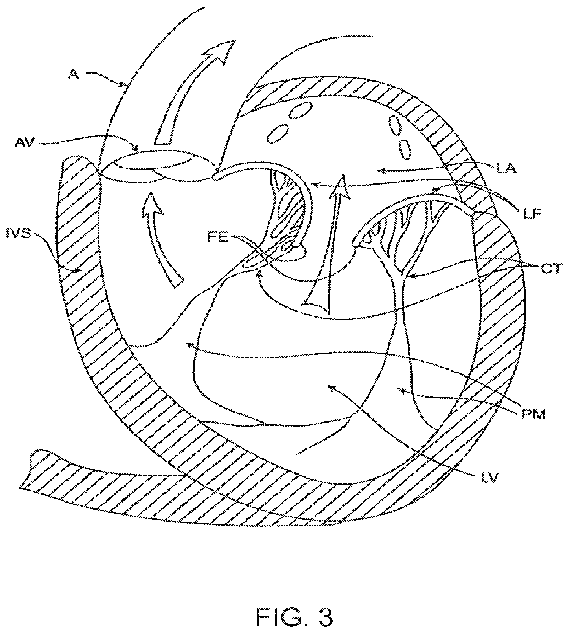
[0027] FIG. 3 is a schematic illustration of a heart in a patient suffering from cardiomyopathy where the heart is dilated and the leaflets do not meet.
[0028] FIG. 3A shows normal closure of the valve leaflets.
[0029] FIG. 3B shows abnormal closure of the valve leaflets.
[0030] FIG. 4 illustrates mitral valve regurgitation in the left ventricle of a heart having impaired papillary muscles.
[0031] FIGS. 5A-5B illustrate anatomy of the mitral valve.
[0032] FIG. 6 illustrates an exemplary embodiment of an uncovered frame in a prosthetic cardiac valve, with the frame flattened out and unrolled.
[0033] FIG. 7 illustrates another exemplary embodiment of an uncovered frame in a prosthetic cardiac valve, with the frame flattened out and unrolled.
[0034] FIG. 8 illustrates still another exemplary embodiment of an uncovered frame in a prosthetic cardiac valve, with the frame flattened out and unrolled.
[0035] FIG. 9A illustrates a perspective view of an uncovered frame in a prosthetic cardiac valve after it has expanded.
[0036] FIG. 9B illustrates a top view of the embodiment in FIG. 9A.
[0037] FIG. 10 illustrates the frame of FIG. 9A with the covering thereby forming a prosthetic cardiac valve.
[0038] FIGS. 11A-11D illustrate an exemplary embodiment of a delivery system used to transapically deliver a prosthetic cardiac valve.
[0039] FIGS. 12A-12L illustrate an exemplary method of implanting a prosthetic cardiac valve.
[0040] FIGS. 13A-13L illustrate another exemplary method of implanting a prosthetic cardiac valve.
[0041] FIGS. 14A-14D illustrate an exemplary embodiment of a tab covering.
[0042] FIG. 15 illustrates a preferred positioning of a prosthetic valve in a native mitral valve.
[0043] FIG. 16 illustrates dislodgement of a prosthetic valve from a native valve.
[0044] FIG. 17 illustrates an alternative embodiment of a prosthetic valve anchored to a native valve.
[0045] FIGS. 18A-18B illustrate a schematic diagram of a prosthetic valve with an anti-pivoting mechanism.
[0046] FIG. 18C illustrates a perspective view of a prosthetic valve with an anti-pivoting mechanism.
[0047] FIG. 19 illustrates an exemplary embodiment of an uncovered prosthetic valve flattened out and unrolled.
[0048] FIGS. 20A-20B illustrate another exemplary embodiment of a prosthetic valve having an anti-pivoting mechanism and a posterior tab.
[0049] FIG. 21 illustrates an exemplary embodiment of a prosthetic valve having an anti-pivoting mechanism with a posterior tab, and barbs.
[0050] FIGS. 22A-22J illustrate another exemplary method of delivering a prosthetic valve to the native valve.
DETAILED DESCRIPTION OF THE INVENTION
[0051] Specific embodiments of the disclosed device, delivery system, and method will now be described with reference to the drawings. Nothing in this detailed description is intended to imply that any particular component, feature, or step is essential to the invention.
[0052] Cardiac Anatomy.
[0053] The left ventricle LV of a normal heart H in systole is illustrated in FIG. 1. The left ventricle LV is contracting and blood flows outwardly through the aortic valve AV, a tricuspid valve in the direction of the arrows. Back flow of blood or "regurgitation" through the mitral valve MV is prevented since the mitral valve is configured as a "check valve" which prevents back flow when pressure in the left ventricle is higher than that in the left atrium LA. The mitral valve MV comprises a pair of leaflets having free edges FE which meet evenly to close, as illustrated in FIG. 1. The opposite ends of the leaflets LF are attached to the surrounding heart structure along an annular region referred to as the annulus AN. The free edges FE of the leaflets LF are secured to the lower portions of the left ventricle LV through chordae tendineae CT (also referred to herein as the chordae) which include a plurality of branching tendons secured over the lower surfaces of each of the valve leaflets LF. The chordae CT in turn, are attached to the papillary muscles PM which extend upwardly from the lower portions of the left ventricle and interventricular septum IVS.
[0054] Referring now to FIGS. 2-4, a number of structural defects in the heart can cause mitral valve regurgitation. Ruptured chordae RCT, as shown in FIG. 2, can cause a valve leaflet LF2 to prolapse since inadequate tension is transmitted to the leaflet via the chordae. While the other leaflet LF1 maintains a normal profile, the two valve leaflets do not properly meet and leakage from the left ventricle LV into the left atrium LA will occur, as shown by the arrow.
[0055] Regurgitation also occurs in the patients suffering from cardiomyopathy where the heart is dilated and the increased size prevents the valve leaflets LF from meeting properly, as shown in FIG. 3. The enlargement of the heart causes the mitral annulus to become enlarged, making it impossible for the free edges FE to meet during systole. The free edges of the anterior and posterior leaflets normally meet along a line of coaptation C as shown in FIG. 3A, but a significant gap G can be left in patients suffering from cardiomyopathy, as shown in FIG. 3B.
[0056] Mitral valve regurgitation can also occur in patients who have suffered ischemic heart disease where the functioning of the papillary muscles PM is impaired, as illustrated in FIG. 4. As the left ventricle LV contracts during systole, the papillary muscles PM do not contract sufficiently to effect proper closure. The leaflets LF1 and LF2 then prolapse, as illustrated. Leakage again occurs from the left ventricle LV to the left atrium LA, as shown by the arrow.
[0057] FIG. 5A more clearly illustrates the anatomy of a mitral valve MV which is a bicuspid valve having an anterior side ANT and a posterior side POST. The valve includes an anterior (aortic) leaflet AL and a posterior (mural) leaflet PL. Chordae tendineae CT couple the valve leaflets AL, PL with the antero-lateral papillary muscle ALPM and the postero-medial papillary muscle PMPM. The valve leaflets AL, PL join one another along a line referred to as the antero-lateral commissure ALC and the posterior-medial commissure PMC. The annulus AN circumscribes the valve leaflets, and two regions adjacent an anterior portion of the annulus, on opposite sides of the anterior leaflet are referred to as the left fibrous trigone LFT and also the right fibrous trigone RFT. These areas are indicted generally by the solid triangles. FIG. 5B more clearly illustrates the left and right fibrous trigones, LFT, RFT.
[0058] While various surgical techniques as well as implantable devices have been proposed and appear to be promising treatments for mitral regurgitation, surgical approaches can require a lengthy recovery period, and implantable devices have varying clinical results. Therefore, there still is a need for improved devices and methods for treating mitral regurgitation. While the embodiments disclosed herein are directed to an implantable prosthetic mitral valve for treating mitral regurgitation, one of skill in the art will appreciate that this is not intended to be limiting, and the device and methods disclosed herein may also be used to treat other cardiac valves such as the tricuspid valve, aortic valve, pulmonary valve, etc, as well as other valves in the body such as venous valves.
[0059] Prosthetic Valve.
[0060] Prosthetic valves have been surgically implanted in the heart as a treatment for mitral regurgitation. Some of these valves have been valves harvested from animals such as porcine valves, and others have been prosthetic mechanical valves with or without a tissue covering. More recently, minimally invasive catheter technology has been used to deliver prosthetic valves to the heart. These valves typically include an anchor for securing the valve to the patient's heart, and a valve mechanism, either a mechanical valve, a valve with animal tissue, or combinations thereof. The prosthetic valve once implanted, takes over for the malfunctioning native valve, thereby reducing or eliminating valvar insufficiency. While some of these valves appear promising, there still is a need for improved valves. Positioning and anchoring the prosthetic valve in the native anatomy remains a challenge. The following specification discloses exemplary embodiments of a prosthetic valve, a delivery system for the prosthetic valve, and methods of delivering the valve that overcome some of the challenges associated with existing prosthetic valves.
[0061] FIG. 6 illustrates an exemplary embodiment of a prosthetic cardiac valve in the collapsed configuration. Coverings from the frame (e.g. fabric or tissue) has been removed to permit observation of the underlying frame 600. The frame has been unrolled and flattened out. The prosthetic valve frame 600 has an atrial region 606, an annular region 608, and a ventricular region 610. The frame 600 is formed from a plurality of interconnected struts that form a series of peaks and valleys which can expand and contract relative to one another thereby permitting the frame to be loaded onto a delivery catheter in a collapsed configuration, and then radially expanded at a target treatment site for implantation. Preferred embodiments are self-expanding and may be fabricated using superelastic nitinol or other self-expanding materials. Shape memory alloys that spring open above a transition temperature may also be used, and expandable members may also be used to expand the frame when plastic deformation (e.g. balloon expansion) is required to open the frame.
[0062] Atrial region 606 has a skirt 616 which includes a plurality of interconnected struts that form a series of peaks and valleys. In this region, the struts are skewed relative to one another and thus the resulting cell pattern has an enlarged end and the opposite end tapers to a smaller end. In preferred embodiments, the anterior portion of the atrial skirt does not have a flanged region like the posterior portion, thus the anterior portion 602 of the atrial region may have shorter struts than the posterior region 604. Thus the peaks and valleys in the anterior portion are axially offset from those in the remaining posterior portion of the atrial region. This may be advantageous as it prevents the struts in the anterior portion of the atrial skirt from protruding upwards potentially impinging against the left atrium and causing perforations. Additionally, the shortened struts and offset peaks and valleys form an alignment element 614 that can assist the physician with visualization of delivery of the prosthetic valve to the mitral valve and also with alignment of the prosthetic valve prior to expansion of the prosthetic valve. Optional radiopaque markers 614a are disposed on either side of the offset peaks and valleys and further help with visualization during implantation of the valve. The atrial region preferably self-expands to either a cylindrical shape, or it may have a D-shaped cross-section where the anterior portion 602 is substantially flat, and the posterior portion 604 is cylindrically shaped. This allows the atrial skirt to conform to the anatomy of the native mitral valve, thereby preventing obstruction of the left ventricular outflow tract. Additionally, the atrial skirt may also be formed so that upon expansion, the skirt flares outward and forms a flange that can rest against a superior surface of the mitral valve. The flanged region is preferably along the posterior portion of the atrial skirt, and the anterior portion of the atrial skirt remains flangeless. Or, the flange may extend entirely around the atrial skirt. The atrial region is connected to the adjacent annular region 608 with connecting struts which are preferably linear and substantially parallel to the longitudinal axis of the frame.
[0063] The annular region 608 is also comprised of a plurality of axially oriented and interconnected struts that form peaks and valleys that allow radial expansion. The struts are preferably parallel with one another and parallel with the longitudinal axis of the frame. The annular region may also be self-expanding and expand into a cylindrical shape, or more preferably the annular region may expand to have a D-shaped cross-section as described above with respect to the atrial region. Thus, the annular region may similarly have a flat anterior portion, and a cylindrically shaped posterior portion. Upon delivery, the annular region is aligned with and expanded into engagement with the mitral valve annulus. Connector struts join the annular region with the ventricular region 610.
[0064] The ventricular region 610 also includes a plurality of interconnected struts that form peaks and valleys. Additionally, the struts in the ventricular region form the leaflet commissures 613 which are covered with fabric, pericardial tissue, or other materials to form the prosthetic valve leaflets. Holes in the commissures allow suture to be attached thereto. Struts in the ventricular region also form a ventricular skirt 628 which expands outward to engage the anterior and posterior mitral valve leaflets, and struts in the ventricular region also form the anterior tabs 624 and the posterior tab 630. The anterior tabs are designed to capture the anterior mitral valve leaflet between an inner surface of the anterior tab and outer surface of the ventricular skirt. Any adjacent chordae tendineae may also be captured therebetween. Also, the tip of the anterior tab engages the fibrous trigone on an anterior portion of the mitral valve, one on the left and one on the right side. The posterior tab similarly captures the posterior mitral valve leaflet between an inner surface of the posterior tab and an outer surface of the ventricular skirt, along with any adjacent chordae tendineae. This will be described in more detail below.
[0065] By controlling strut length or axial position of the anterior or posterior tabs along the frame, deployment of the tabs may be controlled. Thus in this exemplary embodiment, because the length of the struts in the anterior tabs and posterior tabs 624, 630 as well as their relative position along the frame are the same as one another, when a constraining sheath is retracted away from the tabs, the anterior and posterior tabs will partially spring outward together. As the constraining sheath is further retracted, the remainder of the anterior tabs will self-expand radially outward. Further retraction of the constraining sheath then allows the remainder of the posterior tab to finish its radial expansion, and finally the ventricular skirt will radially expand outward. While strut lengths and axial position of the posterior tab and the ventricular skirt are similar, internal struts connect the ventricular skirt with the commissures, and this delays expansion of the ventricular skirt slightly, thus the posterior tab finishes expansion before the ventricular skirt. Using this sequence of deploying the prosthetic valve may allow the valve to more accurately be delivered and also more securely anchored into position.
[0066] Suture holes 621 are disposed along the struts of the annular region as well as the ventricular region to allow attachment of a cover such as pericardium or a polymer such as Dacron or ePTFE. The suture holes may also be disposed along any other part of the frame. Barbs 623 are disposed along the ventricular skirt 628 to help anchor the prosthetic valve to adjacent tissue. Commissure tabs or tabs 612 are disposed on the tips of the commissures 613 and may be used to releasably couple the commissures with a delivery system as will be described below. This allows the frame to expand first, and then the commissures may be released from the delivery system afterwards. One of skill in the art will appreciate that a number of strut geometries may be used, and additionally that strut dimensions such as length, width, thickness, etc. may be adjusted in order to provide the prosthesis with the desired mechanical properties such as stiffness, radial crush strength, commissure deflection, etc. Therefore, the illustrated geometry is not intended to be limiting.
[0067] The frame may be formed by electrical discharge machining (EDM), laser cutting, photochemical etching, or other techniques known in the art. Hypodermic tubing or flat sheets may be used to form the frame. Once the frame has been cut and formed into a cylinder (if required), it may be radially expanded into a desired geometry and heat treated using known processes to set the shape. Thus, the prosthetic valve may be loaded onto a delivery catheter in a collapsed configuration and constrained in the collapsed configuration with a constraining sheath. Removal of the constraining sheath will allow the prosthesis to self-expand into its unbiased pre-set shape. In other embodiments, an expandable member such as a balloon may be used to radially expand the prosthesis into its preferred expanded configuration.
[0068] FIG. 7 illustrates another exemplary embodiment of a prosthetic cardiac valve in the collapsed configuration, and similar to the previous embodiment with the major difference being the strut lengths in the anterior tabs, posterior tab, and ventricular skirt. Varying the strut lengths allow the sequence of expansion of the anterior and posterior tabs and ventricular skirt to be controlled. Coverings from the frame (e.g. fabric or tissue) has been removed to permit observation of the underlying frame 700. The frame has been unrolled and flattened out. The prosthetic valve frame 700 has an atrial region 706, an annular region 708, and a ventricular region 710. The frame 700 is formed from a plurality of interconnected struts that form a series of peaks and valleys which can expand and contract relative to one another thereby permitting the frame to be loaded onto a delivery catheter in a collapsed configuration, and then radially expanded at a target treatment site for implantation. Preferred embodiments are self-expanding and may be fabricated using superelastic nitinol or other self-expanding materials. Shape memory alloys that spring open above a transition temperature may also be used, and expandable members may also be used to expand the frame when plastic deformation (e.g. balloon expansion) is required to open the frame.
[0069] Atrial region 706 has a skirt 716 which includes a plurality of interconnected struts that form a series of peaks and valleys. In this region, the struts are skewed relative to one another and thus the resulting cell pattern has an enlarged end and the opposite end tapers to a smaller end. An anterior portion 702 of the atrial region has shorter struts than the posterior region 704. Thus the peaks and valleys in the anterior portion are axially offset from those in the remaining posterior portion of the atrial region. This allows creation of an alignment element 714 to help the physician deliver the prosthetic valve to the mitral valve and align the prosthetic valve prior to expansion of the prosthetic valve. Other aspects of the atrial region 706 are similar to those of the atrial region 606 in FIG. 6. Optional radiopaque markers 714a are disposed on either side of the offset peaks and valleys and help with visualization during implantation of the valve. The atrial region preferably self-expands to either a cylindrical shape, or it may have a D-shaped cross-section where the anterior portion 702 is substantially flat, and the posterior portion 704 is cylindrically shaped. This allows the atrial skirt to conform to the anatomy of the native mitral valve, thereby preventing obstruction of the left ventricular outflow tract. Additionally, the atrial skirt may also be formed so that upon expansion, the skirt flares outward and forms a flange that can rest against a superior surface of the mitral valve. The flanged region is preferably along the posterior portion of the atrial skirt, and the anterior portion of the atrial skirt remains flangeless. Or, the flange may extend entirely around the atrial skirt. The atrial region is connected to the adjacent annular region 708 with connecting struts which are preferably linear and substantially parallel to the longitudinal axis of the frame.
[0070] The annular region 708 is also comprised of a plurality of axially oriented and interconnected struts that form peaks and valleys that allow radial expansion. The struts are preferably parallel with one another and parallel with the longitudinal axis of the frame. The annular region may also be self-expanding and expand into a cylindrical shape, or more preferably the annular region may expand to have a D-shaped cross-section as described above with respect to the atrial region. Thus, the annular region may similarly have a flat anterior portion, and a cylindrically shaped posterior portion. Upon delivery, the annular region is aligned with and expanded into engagement with the mitral valve annulus. Connector struts join the annular region with the ventricular region 710.
[0071] The ventricular region 710 also includes a plurality of interconnected struts that form peaks and valleys. Additionally, the struts in the ventricular region form the leaflet commissures 713 which are covered with fabric, pericardial tissue, or other materials to form the prosthetic valve leaflets. Holes in the commissures allow suture to be attached thereto. Struts in the ventricular region also form a ventricular skirt 728 which expands outward to engage the anterior and posterior mitral valve leaflets, and struts in the ventricular region also form the anterior tabs 724 and the posterior tab 730. The anterior tabs are designed to capture the anterior mitral valve leaflet between an inner surface of the anterior tab and outer surface of the ventricular skirt. Any adjacent chordae tendineae may also be captured therebetween. Also, the tip of the anterior tab engages the fibrous trigone on an anterior portion of the mitral valve, one on the left and one on the right side. The posterior tab similar captures the posterior mitral valve leaflet between an inner surface of the posterior tab and an outer surface of the ventricular skirt, along with any adjacent chordae tendineae. This will be described in more detail below.
[0072] By controlling strut length or axial position of the anterior or posterior tabs along the frame, deployment of the tabs may be controlled. Thus in this exemplary embodiment, because the length of the struts in the anterior tabs and posterior tabs 724, 730 as well as their relative position along the frame are the same as one another, when a constraining sheath is retracted away from the tabs, the anterior and posterior tabs will partially spring outward together. As the constraining sheath is further retracted, the remainder of the anterior tabs will self-expand radially outward because they are the shortest relative to the struts in the ventricular skirt and the posterior tab. Further retraction of the constraining sheath then allows the ventricular skirt to radially expand, and finally further retraction of the sheath allows the remainder of the posterior tab to finish its radial expansion. Using this sequence of deploying the prosthetic valve may allow the valve to more accurately be delivered and also more securely anchored into position.
[0073] Suture holes 721 are disposed along the struts of the annular region as well as the ventricular region to allow attachment of a cover such as pericardium or a polymer such as Dacron or ePTFE. The suture holes may also be disposed along any other part of the frame. Barbs 723 are disposed along the ventricular skirt 728 to help anchor the prosthetic valve to adjacent tissue. Commissure tabs or tabs 712 are disposed on the tips of the commissures 713 and may be used to releasably couple the commissures with a delivery system as will be described below. This allows the frame to expand first, and then the commissures may be released from the delivery system afterwards. One of skill in the art will appreciate that a number of strut geometries may be used, and additionally that strut dimensions such as length, width, thickness, etc. may be adjusted in order to provide the prosthesis with the desired mechanical properties such as stiffness, radial crush strength, commissure deflection, etc. Therefore, the illustrated geometry is not intended to be limiting. The frame may be formed similarly as described above with respect to FIG. 6.
[0074] FIG. 8 illustrates another exemplary embodiment of a prosthetic cardiac valve in the collapsed configuration, and is similar to the previous embodiments, with the major difference being that the posterior tab is designed to expand to form an elongate horizontal section which allows engagement and anchoring of the posterior tab with the sub-annular region between the posterior leaflet and the ventricular wall. Thus, the elongate horizontal section contacts a larger region of the sub-annular region as compared with a posterior tab that only has a tapered tip formed from a single hinge between struts. This provides enhanced anchoring of the prosthetic valve. In this exemplary embodiment, the anterior tabs will completely self-expand first, followed by the posterior tab and then the ventricular skirt. However, in some situations external factors such as the delivery system, anatomy, etc. may alter the sequence of expansion, and therefore this is not intended to be limiting. Coverings from the frame (e.g. fabric or tissue) have been removed to permit observation of the underlying frame 800. The frame has been unrolled and flattened out. The prosthetic valve frame 800 has an atrial region 806, an annular region 808, and a ventricular region 810. The frame 800 is formed from a plurality of interconnected struts that form a series of peaks and valleys which can expand and contract relative to one another thereby permitting the frame to be loaded onto a delivery catheter in a collapsed configuration, and then radially expanded at a target treatment site for implantation. Preferred embodiments are self-expanding and may be fabricated using superelastic nitinol or other self-expanding materials. Shape memory alloys that spring open above a transition temperature may also be used, and expandable members may also be used to expand the frame when plastic deformation (e.g. balloon expansion) is required to open the frame.
[0075] Atrial region 806 has a skirt 816 which includes a plurality of interconnected struts that form a series of peaks and valleys. In this region, the struts are skewed relative to one another and thus the resulting cell pattern has an enlarged end and the opposite end tapers to a smaller end. An anterior portion 802 of the atrial region has shorter struts than the posterior region 804. Thus the peaks and valleys in the anterior portion are axially offset from those in the remaining posterior portion of the atrial region. This allows creation of an alignment element 814 to help the physician deliver the prosthetic valve to the mitral valve and align the prosthetic valve prior to expansion of the prosthetic valve. Other aspects of the atrial region 806 are similar to those of the atrial region 606 in FIG. 6. Optional radiopaque markers 814a are disposed on either side of the offset peaks and valleys and help with visualization during implantation of the valve. The atrial region preferably self-expands to either a cylindrical shape, or it may have a D-shaped cross-section where the anterior portion 802 is substantially flat, and the posterior portion 804 is cylindrically shaped. This allows the atrial skirt to conform to the anatomy of the native mitral valve, thereby preventing obstruction of the left ventricular outflow tract. Additionally, the atrial skirt may also be formed so that upon expansion, the skirt flares outward and forms a flange that can rest against a superior surface of the mitral valve. The flanged region is preferably along the posterior portion of the atrial skirt, and the anterior portion of the atrial skirt remains flangeless. Or, the flange may extend entirely around the atrial skirt. The atrial region is connected to the adjacent annular region 808 with connecting struts which are preferably linear and substantially parallel to the longitudinal axis of the frame.
[0076] The annular region 808 is also comprised of a plurality of axially oriented and interconnected struts that form peaks and valleys that allow radial expansion. The struts are preferably parallel with one another and parallel with the longitudinal axis of the frame. The annular region may also be self-expanding and expand into a cylindrical shape, or more preferably the annular region may expand to have a D-shaped cross-section as described above with respect to the atrial region. Thus, the annular region may similarly have a flat anterior portion, and a cylindrically shaped posterior portion. Upon delivery, the annular region is aligned with and expanded into engagement with the mitral valve annulus. Connector struts join the annular region with the ventricular region 810.
[0077] The ventricular region 810 also includes a plurality of interconnected struts that form peaks and valleys. Additionally, the struts in the ventricular region form the leaflet commissures 813 which are covered with fabric, pericardial tissue, or other materials to form the prosthetic valve leaflets. Holes in the commissures allow suture to be attached thereto. Struts in the ventricular region also form a ventricular skirt 828 which expands outward to engage the anterior and posterior mitral valve leaflets, and struts in the ventricular region also form the anterior tabs 824 and the posterior tab 830. The anterior tabs are designed to capture the anterior mitral valve leaflet between an inner surface of the anterior tab and outer surface of the ventricular skirt. Any adjacent chordae tendineae may also be captured therebetween. Also, the tip of the anterior tab engages the fibrous trigone on an anterior portion of the mitral valve, one on the left and one on the right side. The posterior tab similarly captures the posterior mitral valve leaflet between an inner surface of the posterior tab and an outer surface of the ventricular skirt, along with any adjacent chordae tendineae. This will be described in more detail below. The posterior tab is similar to the posterior tabs described above in FIGS. 6-7, except that in this embodiment, the posterior tab comprises four interconnected struts as opposed to two interconnected struts. Thus, in this embodiment the plurality of interconnected struts form three hinged regions 836 along the tab. Upon expansion of the posterior tab, the hinged regions will also expand, thereby forming an elongate horizontal section which allows engagement and anchoring of the posterior tab with the sub-annular region between the posterior leaflet and the ventricular wall. This may help position and anchor the prosthetic valve better than posterior tabs which only have a smaller footprint or a single tapered tip for engagement with the posterior portion of the mitral valve. The posterior tab in this embodiment, may be substituted with any of the other posterior tabs described in this specification.
[0078] By controlling strut length or axial position of the anterior or posterior tabs along the frame, deployment of the tabs may be controlled. Thus in this exemplary embodiment, because the length of the struts in the anterior tabs and posterior tabs 824, 830 as well as their relative position along the frame are the same as one another, when a constraining sheath is retracted away from the tabs, the anterior and posterior tabs will partially spring outward together. As the constraining sheath is further retracted, the remainder of the anterior tabs will self-expand radially outward because they are the shortest relative to the struts in the ventricular skirt and the posterior tab. Further retraction of the constraining sheath then allows the remainder of the posterior tab to finish self-expanding, followed by self-expansion of the ventricular skirt. Using this sequence of deploying the prosthetic valve may allow the valve to more accurately be delivered and also more securely anchored into position.
[0079] Suture holes 821 are disposed along the struts of the annular region as well as the ventricular region to allow attachment of a cover such as pericardium or a polymer such as Dacron or ePTFE. The suture holes may also be disposed along any other part of the frame. Barbs 823 are disposed along the ventricular skirt 828 to help anchor the prosthetic valve to adjacent tissue. Commissure tabs or tabs 812 are disposed on the tips of the commissures 813 and may be used to releasably couple the commissures with a delivery system as will be described below. This allows the frame to expand first, and then the commissures may be released from the delivery system afterwards. One of skill in the art will appreciate that a number of strut geometries may be used, and additionally strut dimensions such as length, width, thickness, etc. may be adjusted in order to provide the prosthesis with the desired mechanical properties such as stiffness, radial crush strength, commissure deflection, etc. Therefore, the illustrated geometry is not intended to be limiting. The frame may be formed similarly as described above.
[0080] FIG. 9A illustrates the frame 900 of a prosthetic cardiac valve after it has expanded. Any of the frame embodiments described above may take this form as each of the above frames have similar geometry but they expand in different order. The frame includes the atrial skirt 906 with anterior portion 914 and posterior portion 916. A flanged region is formed around the posterior portion and the anterior portion remains flangeless. Additionally, the anterior portion is generally flat, while the posterior portion is cylindrically shaped, thereby forming a D-shaped cross-section which accommodates the mitral valve anatomy. FIG. 9B is a top view of the embodiment in FIG. 9A and more clearly illustrates the D-shaped cross-section.
[0081] The frame also includes the annular region 910 and ventricular skirt 912. Anterior tabs 904 (only one visible in this view) is fully expanded such that a space exists between the inner surface of the anterior tab and an outer surface of the ventricular skirt. This allows the anterior leaflet and adjacent chordae to be captured therebetween. Similarly, the posterior tab 902 is also fully deployed, with a similar space between the inner surface of the posterior tab 902 and an outer surface of the ventricular skirt. This allows the posterior leaflet and adjacent chordae tendineae to be captured therebetween. The commissure posts 908 are also visible and are disposed in the inner channel formed by the frame. The commissure posts are used to form the prosthetic mitral valve leaflets. The overall shape of the expanded frame is D-shaped, with the anterior portion flat and the posterior portion cylindrically shaped.
[0082] FIG. 10 illustrates the expanded frame covered with a cover 1002 such as pericardial tissue or a polymer such as ePTFE or a fabric like Dacron attached to the frame, thereby forming the prosthetic cardiac valve 1000. The atrial skirt may be entirely covered by a material, or in preferred embodiments, the covering is only disposed between adjacent struts 1012 in adjacent cells in the flanged portion of the atrial skirt. The area 1014 between adjacent struts within the same cell remain uncovered. This allows blood flow to remain substantially uninterrupted while the prosthetic valve is being implanted. Suture 1010 may be used to attach the cover to the frame. In this view, only the posterior tab 1006 is visible on the posterior portion of the prosthetic valve along with ventricular skirt 1008 and atrial skirt 1004.
[0083] Anti-Pivoting Mechanism
[0084] As discussed above, preferred embodiments of the device anchor the prosthetic valve to the anterior and posterior valve leaflets. FIG. 15 illustrates an example of this where the prosthetic valve 1506 which may be any of the embodiments having both anterior and posterior tabs described herein, is successfully anchored to the mitral valve 1502 of a patient's heart H. The posterior tab 1508 has successfully engaged the posterior leaflet 1504, and the anterior tab 1510 has successfully engaged the anterior leaflet 1512. Proper anterior and posterior anchoring secures the inferior portion of the prosthetic valve and prevents unwanted rotation or pivoting of the prosthetic valve, as well as preventing unwanted axial movement upstream or downstream. However, as previously discussed, in certain situations the posterior tab may not anchor the prosthetic device to the posterior leaflet of native valve. For example, if the physician improperly delivers and deploys the prosthetic valve it may not properly engage the posterior leaflet. Or, in some situations, the posterior leaflet may have an irregular shape or may be fragile and therefore not be strong enough for anchoring with the posterior tab.
[0085] When the posterior tab fails to anchor the prosthetic valve to the posterior leaflet, the prosthetic valve will only be anchored with the anterior tabs and therefore may pivot or rotate counter-clockwise, or upward into the left atrium as seen in FIG. 16 which illustrates the prosthetic valve 1506 rotating due to the retrograde blood pressure from the left ventricle of the heart H and exerted on the prosthesis during systole. The posterior portion of the prosthesis pivots upward into the left atrium creating a leak around the prosthesis as indicated by the arrows.
[0086] FIG. 17 illustrates an alternative embodiment of prosthetic valve that helps prevent posterior pivoting. The prosthetic valve 1702 in this embodiment is a prosthetic mitral valve and it is implanted in a native mitral valve 1502 of a patient's heart H. The prosthetic valve 1702 generally takes the same form as other prosthetic valves described in this specification, with the major exception that it does not have posterior tabs. Instead of the posterior tabs, the prosthetic valve includes a foot 1704 which prevents pivoting. The foot is an enlarged portion of the prosthetic valve that extends radially outward from the body of the prosthesis sufficiently far so that the cross-sectional area of the ventricular portion of the prosthetic valve is large enough to prevent it from pivoting or rotating up into the atrium. Thus, blood flows out the left ventricle into the aorta during systole and retrograde flow into the atrium is eliminated or substantially reduced. Leaks around the prosthetic valve are also reduced or eliminated. The foot may be any number of structures which prevent pivoting of the prosthesis.
[0087] FIGS. 18A-18B illustrate a schematic of a prosthetic valve having an anti-pivoting mechanism. FIG. 18A illustrates the prosthetic valve 1802 which is generally the same as any of the other valve embodiments described herein with the major difference being that it does not have a posterior tab. The prosthetic valve 1802 may have any of the features described in any other embodiments disclosed herein. For example, the prosthetic valve may include an atrial flange 1804, an annular region 1808 and a ventricular region or ventricular skirt 1814. The valve preferably also includes two anterior tabs 1806 for engaging the anterior leaflet and the trigones. Also, the valve has a foot 1812 which is a wedge shaped region of the prosthesis that extends radially outward. FIG. 18B illustrates a top view of the prosthetic valve 1802 seen in FIG. 18A.
[0088] FIG. 18C illustrates a perspective view of a prosthetic valve 1802 that generally takes the same form as other valve embodiments described herein with the major difference being that instead of having a posterior tab for anchoring to a valve leaflet, the valve has a foot 1812 which anchors the posterior part of the valve to the posterior portion of the native valve. The valve includes an atrial flange 1804, anterior trigonal tabs 1806, an annular region 1808, and a ventricular skirt region 1818 that generally take the same form as described in other embodiments. The foot 1812 may be any structure which extends radially outward and prevents the prosthetic valve from rotating or pivoting. In some embodiments, the foot may extend radially outward 10 mm or more. In this embodiment, the foot includes a central element 1812 which has been formed from two struts 1814 that are coupled together with a connector to form a V or U-shaped structure that extends radially outward. A cover 1816 such as pericardial tissue, or any of the other cover materials discussed herein is attached to the central element 1812 and to adjacent struts on either side, thereby forming a vestibule similar to that seen on a camping tent, or a cattle pusher on a locomotive engine (sometimes referred to as a pilot). This structure has a larger cross-section than the native valve, and thus it prevents the prosthetic valve from rotating through the valve into the atrium (in the case of a mitral valve prosthesis).
[0089] FIG. 19 illustrates a flat pattern used to cut the prosthetic valve from tubing or a flat sheet which is then rolled and welded into a cylinder. Electrical discharge machining (EDM), laser cutting, or photochemical etching are techniques used to cut the flat pattern. The prosthesis 1902 generally takes the same form as other prosthetic valves disclosed herein, and thus not every feature will be described in detail. The prosthesis 1902 includes an atrial region 1910 having an atrial skirt, an annular region 1912 and a ventricular region 1914. The ventricular region includes anterior tabs 1904 with tips 1908 that engage the fibrous trigones on either side of the anterior leaflet of a mitral valve. The anti-pivoting mechanism is formed from an elongate pair of struts 1906 which extend axially further than the struts of the ventricular region. The struts 1906 may be formed to flare radially outward upon self-expansion and they may be covered with tissue or synthetic material to form the enlarged area of the foot which prevents pivoting. Other aspects of the prosthetic valve such as the atrial flange, the annular region, the ventricular skirt, suture holes, commissure posts, commissure tabs, alignment element, flat anterior shape, cylindrical posterior shape, D-shaped cross-section may generally take the same form as described in other embodiments of this specification. The prosthetic valve is preferably formed from shape memory or superelastic nitinol, or it may be made from other self-expanding materials known in the art. The valve may also be balloon expandable and be made from materials such as stainless steel, cobalt-chromium, or other materials known in the art. The foot may take any number of shapes and may be a combination of metal or fabric and/or polymer features coupled integral with or coupled to the prosthetic valve. The anchoring elements on the prosthetic valve may be deployed in any desired order. However, in preferred embodiments, the atrial skirt deploys first and anchors the valve to the atrial floor followed by deployment of the annular region into the annulus, then the anterior tabs capture the valve leaflets, followed by the foot, and then the ventricular skirt, and then the commissures.
[0090] FIGS. 20A-20B illustrate another exemplary embodiment of a prosthetic valve combining features of several previously disclosed embodiments such as the foot and a posterior tab. FIG. 20A illustrates a rear view looking head on at a prosthetic valve 2002 which may take the form of any of the embodiments disclosed herein. The upper end of the prosthesis includes an atrial flange 2004 which helps anchor the device to the floor of the atrium as previously described. The prosthesis also includes a pair of anterior trigonal tabs for anchoring the prosthesis to the fibrous trigones of the anterior portion of the valve annulus. The posterior portion of the prosthesis includes a foot 2008 like the foot previously described above, and a posterior tab 2010 which may take the form of any of the previous embodiments. Other portions of the prosthesis may take the form of any previous embodiment described herein, including but not limited to the annular region, ventricular region, commissures, etc. Having both a posterior tab and a foot provides a fail-safe anchoring mechanism on the prosthesis. Thus, in case the posterior tab fails to anchor the device to the posterior portion of the valve, the foot anchors the device as described before and prevents unwanted pivoting of the prosthesis upward. FIG. 20B illustrates another side view of the prosthesis 2020, this time rotated about its longitudinal axis to more clearly illustrate one anterior tab (the other is obstructed), as well as the foot and the posterior tab. In addition to having a posterior tab and a foot, alternative embodiments may also have barbs, texturing or other surface features on the foot, the posterior tab, or adjacent thereto in order to help further anchor the prosthesis into the tissue.
[0091] FIG. 21 illustrates an exemplary embodiment of a prosthesis 2102 having a foot 2110, posterior tab 2106, anterior tab 2106 and barbs 2112. The barbs may be pointed protrusions, or they may be textured regions. They may be disposed on the foot, on the posterior tab, or on both portions of the device. Other aspects of the prosthesis such as the atrial flange 2104, anterior tab 2106, as well as other features including the annular skirt, ventricular skirt, commissures, etc. may take the form of any embodiment described herein.
[0092] Delivery System.
[0093] FIGS. 11A-11D illustrate an exemplary embodiment of a delivery system that may be used to deliver any of the prosthetic cardiac valves disclosed in this specification. While the delivery system is designed to preferably deliver the prosthetic cardiac valve transapically, one of skill in the art will appreciate that it may also be modified so that the prosthetic valve may be delivered via a catheter transluminally, such using a transseptal route. One of skill in the art will appreciate that using a transseptal route may require the relative motion of the various shafts to be modified in order to accommodate the position of the delivery system relative to the mitral valve.
[0094] FIG. 11A illustrates a perspective view of delivery system 1100. The delivery system 1100 includes a handle 1112 near a proximal end of the delivery system and a distal tissue penetrating tip 1110. Four elongate shafts are included in the delivery system and include an outer sheath catheter shaft 1102, a bell catheter shaft 1104 which is slidably disposed in the outer sheath catheter shaft 1102, a hub catheter shaft 1106 which remains stationary relative to the other shafts, but the bell catheter shaft slides relative to the hub shaft, and finally an inner guidewire catheter shaft 1108 which is also fixed relative to the other shafts and has a lumen sized to receive a guidewire which passes therethrough and exits the distal tissue penetrating tip. An actuator mechanism 1114 is used to control movement of the various shafts as will be explained in greater detail below, and flush lines 1116, 1118 with luer connectors are used to flush the annular regions between adjacent shafts. Flush line 1118 is used to flush the annular space between the outer sheath catheter shaft 1102 and the bell catheter shaft 1104. Flush line 1116 is used to flush the annular space between the bell catheter 1104 and the hub catheter 1106. The inner guidewire catheter shaft 1108 is stationary relative to the hub catheter 1106 therefore the annular space may be sealed with an o-ring or other material. Luer connector 1122 allows flushing of the guidewire lumen and a hemostatic valve such as a Tuohy-Borst may be coupled to the luer connector to allow a guidewire to be advanced through the guidewire catheter shaft while maintaining hemostasis. Screws 1120 keep the handle housing coupled together. FIG. 11B illustrates a side view of the delivery system 1100.
[0095] FIG. 11C is a partial exploded view of the delivery system 1100 and more clearly illustrates the components in the handle 1112 and how they interact. The handle 1112 includes a housing having two halves 1112a, 1112b which hold all the components. The handle is preferably held together with screws 1120 and nuts 1120b, although it may also be sealed using other techniques such as a press fit, snap fit, adhesive bonding, ultrasonic welding, etc. Rotation of actuator wheel 1114 is translated into linear motion of threaded insert 1124. The outer sheath catheter shaft 1102 is coupled to the threaded insert 1124, therefore rotation of actuator wheel 1114 in one direction will advance the sheath catheter shaft 1102, and rotation in the opposite direction will retract the sheath catheter shaft 1102. Further rotation of actuator wheel 1114 retracts threaded insert 1124 enough to bump into pins 1126 which are coupled to insert 1128, thereby also moving insert 1128. The bell catheter shaft 1106 is coupled to insert 1128, therefore further rotation of the actuator wheel 1114 will move the outer shaft 1102 and also move the bell catheter shaft 1106. Rotation of the actuator wheel in the opposite direction advances the sheath and threaded insert 1124 disengages from pins 1126. Spring 1130 returns insert 1128 to its unbiased position, thereby returning the bell catheter shaft to its unbiased position.
[0096] Any of the prosthetic cardiac valves disclosed herein may be carried by delivery system 1100. The atrial skirt, annular skirt, anterior tabs, posterior tab and ventricular skirt are loaded over the bell catheter shaft and disposed under the outer sheath catheter shaft 1102. The ventricular skirt is loaded proximally so that it is closest to the handle 112 and the atrial skirt is loaded most distally so it is closest to the tip 1110. Therefore, retraction of outer sheath catheter shaft 1102 plays a significant part in controlling deployment of the prosthetic cardiac valve. The atrial skirt therefore expands first when the outer sheath catheter is retracted. The prosthetic valve commissures may be coupled with a hub 1106a on the distal portion of hub catheter 1106 and then the bell catheter shaft is disposed thereover, thereby releasably engaging the commissures with the delivery catheter. Once other portions of the prosthetic cardiac valve have expanded, the commissures may be released.
[0097] FIG. 11D highlights the distal portion of the delivery system 1100. Outer sheath catheter shaft 1102 advances and retracts relative to bell catheter shaft 1104 which is slidably disposed in the outer sheath catheter shaft 1102. Hub catheter shaft 1106 is shown slidably disposed in bell catheter shaft 1104 and with bell catheter shaft 1104 retracted so as to expose the hub 1106a having slots 1106b that hold the prosthetic valve commissures. Inner guidewire catheter shaft 1108 is the innermost shaft and has a tapered conical section 1130 which provides a smooth transition for the prosthetic valve and prevents unwanted bending or buckling of the prosthetic cardiac valve frame. Tissue penetrating tip 1110 is adapted to penetrate tissue, especially in a cardiac transapical procedure.
[0098] Delivery Method.
[0099] A number of methods may be used to deliver a prosthetic cardiac valve to the heart. Exemplary methods of delivering a prosthetic mitral valve may include a transluminal delivery route which may also be a transseptal technique which crosses the septum between the right and left sides of the heart, or in more preferred embodiments, a transapical route may be used such as illustrated in FIGS. 12A-12L. The delivery device previously described above may be used to deliver any of the embodiments of prosthetic valves described herein, or other delivery devices and other prosthetic valves may also be used, such as those disclosed in U.S. patent application Ser. No. 13/096,572, previously incorporated herein by reference. However, in this preferred exemplary embodiment, the prosthetic cardiac valve of FIG. 6 is used so that the anterior tabs deploy first, followed by the posterior tab, and then the ventricular skirt. In the embodiment where the prosthetic valve has a foot instead of a posterior tab, deployment is generally the same, but the foot is expanded instead of the posterior tab.
[0100] FIG. 12A illustrates the basic anatomy of the left side of a patient's heart including the left atrium LA and left ventricle LV. Pulmonary veins PV return blood from the lungs to the left atrium and the blood is then pumped from the left atrium into the left ventricle across the mitral valve MV. The mitral valve includes an anterior leaflet AL on an anterior side A of the valve and a posterior leaflet PL on a posterior side P of the valve. The leaflets are attached to chordae tendineae CT which are subsequently secured to the heart walls with papillary muscles PM. The blood is then pumped out of the left ventricle into the aorta Ao with the aortic valve AV preventing regurgitation.
[0101] FIG. 12B illustrates transapical delivery of a delivery system 1202 through the apex of the heart into the left atrium LA via the left ventricle LV. The delivery system 1202 may be advanced over a guidewire GW into the left atrium, and a tissue penetrating tip 1204 helps the delivery system pass through the apex of the heart by dilating the tissue and forming a larger channel for the remainder of the delivery system to pass through. The delivery catheter carries prosthetic cardiac valve 1208. Once the distal portion of the delivery system has been advanced into the left atrium, the outer sheath 1206 may be retracted proximally (e.g. toward the operator) thereby removing the constraint from the atrial portion of the prosthetic valve 1208. This allows the atrial skirt 1210 to self-expand radially outward. In FIG. 12C, as the outer sheath is further retracted, the atrial skirt continues to self-expand and peek out, until it fully deploys as seen in FIG. 12D. The atrial skirt may have a cylindrical shape or it may be D-shaped as discussed above with a flat anterior portion and a cylindrical posterior portion so as to avoid interfering with the aortic valve and other aspects of the left ventricular outflow tract. The prosthesis may be oriented and properly positioned by rotating the prosthesis and visualizing the alignment element previously described. Also, the prosthetic cardiac valve may be advanced upstream or downstream to properly position the atrial skirt. In preferred embodiments, the atrial skirt forms a flange that rests against a superior surface of the mitral valve and this anchors the prosthetic valve and prevents it from unwanted movement downstream into the left ventricle.
[0102] As the outer sheath 1206 continues to be proximally retracted, the annular region of the prosthetic cardiac valve self-expands next into engagement with the valve annulus. The annular region also preferably has the D-shaped geometry, although it may also be cylindrical or have other geometries to match the native anatomy. In FIG. 12E, retraction of sheath 1206 eventually allows both the anterior 1212 and posterior 1214 tabs to partially self-expand outward preferably without engaging the anterior or posterior leaflets or the chordae tendineae. In this embodiment, further retraction of the outer sheath 1206 then allows both the anterior tabs 1212 (only one visible in this view) to complete their self-expansion so that the anterior leaflet is captured between an inner surface of each of the anterior tabs and an outer surface of the ventricular skirt 1216, as illustrated in FIG. 12F. The posterior tab 1214 remains partially open, but has not completed its expansion yet. Additionally, the tips of the anterior tabs also anchor into the left and right fibrous trigones of the mitral valve, as will be illustrated in greater detail below.
[0103] In FIG. 12G, further retraction of the outer sheath 1206 then releases the constraints from the posterior tab 1214 allowing it to complete its self-expansion, thereby capturing the posterior leaflet PL between an inner surface of the posterior tab 1214 and an outer surface of the ventricular skirt 1218. In FIG. 12H, the sheath is retracted further releasing the ventricular skirt 1220 and allowing the ventricular skirt 1220 to radially expand outward, further capturing the anterior and posterior leaflets between the outer surface of the ventricular skirt and their respective anterior or posterior tabs. Expansion of the ventricular skirt also pushes the anterior and posterior leaflets outward, thereby ensuring that the native leaflets do not interfere with any portion of the prosthetic valve or the prosthetic valve leaflets. The prosthetic valve is now anchored in position above the mitral valve, along the annulus, to the valve leaflets, and below the mitral valve, thereby securing it in position.
[0104] Further actuation of the delivery device now retracts the outer sheath 1206 and the bell catheter shaft 1222 so as to remove the constraint from the hub catheter 1224, as illustrated in FIG. 12I. This permits the prosthetic valve commissures 1226 to be released from the hub catheter, thus the commissures expand to their biased configuration. The delivery system 1202 and guidewire GW are then removed, leaving the prosthetic valve 1208 in position where it takes over for the native mitral valve, as seen in FIG. 12J.
[0105] FIGS. 12K and 12L highlight engagement of the anterior and posterior tabs with the respective anterior and posterior leaflets. In FIG. 12K, after anterior tabs 1212 have been fully expanded, they capture the anterior leaflet AL and adjacent chordae tendineae between an inside surface of the anterior tab and an outer surface of the ventricular skirt 1220. Moreover, the tips 1228 of the anterior tabs 1212 are engaged with the fibrous trigones FT of the anterior side of the mitral valve. The fibrous trigones are fibrous regions of the valve thus the anterior tabs further anchor the prosthetic valve into the native mitral valve anatomy. One anterior tab anchors into the left fibrous trigone, and the other anterior tabs anchors into the right fibrous trigone. The trigones are on opposite sides of the anterior side of the leaflet. FIG. 12L illustrates engagement of the posterior tab 1214 with the posterior leaflet PL which is captured between an inner surface of the posterior tab and an outer surface of the ventricular skirt 1220. Additionally, adjacent chordae tendineae are also captured between the posterior tab and ventricular skirt.
[0106] FIGS. 13A-13L illustrate another exemplary embodiment of a delivery method. This embodiment is similar to that previously described, with the major difference being the order in which the prosthetic cardiac valve self-expands into engagement with the mitral valve. Any delivery device or any prosthetic cardiac valve disclosed herein may be used, however in preferred embodiments, the embodiment of FIG. 7 is used. Varying the order may allow better positioning of the implant, easier capturing of the valve leaflets, and better anchoring of the implant. This exemplary method also preferably uses a transapical route, although transseptal may also be used.
[0107] FIG. 13A illustrates the basic anatomy of the left side of a patient's heart including the left atrium LA and left ventricle LV. Pulmonary veins PV return blood from the lungs to the left atrium and the blood is then pumped from the left atrium into the left ventricle across the mitral valve MV. The mitral valve includes an anterior leaflet AL on an anterior side A of the valve and a posterior leaflet PL on a posterior side P of the valve. The leaflets are attached to chordae tendineae CT which are subsequently secured to the heart walls with papillary muscles PM. The blood is then pumped out of the left ventricle into the aorta AO with the aortic valve AV preventing regurgitation.
[0108] FIG. 13B illustrates transapical delivery of a delivery system 1302 through the apex of the heart into the left atrium LA via the left ventricle LV. The delivery system 1302 may be advanced over a guidewire GW into the left atrium, and a tissue penetrating tip 1304 helps the delivery system pass through the apex of the heart by dilating the tissue and forming a larger channel for the remainder of the delivery system to pass through. The delivery catheter carries prosthetic cardiac valve 1308. Once the distal portion of the delivery system has been advanced into the left atrium, the outer sheath 1306 may be retracted proximally (e.g. toward the operator) thereby removing the constraint from the atrial portion of the prosthetic valve 1308. This allows the atrial skirt 1310 to self-expand radially outward. In FIG. 13C, as the outer sheath is further retracted, the atrial skirt continues to self-expand and peek out, until it fully deploys as seen in FIG. 13D. The atrial skirt may have a cylindrical shape or it may be D-shaped as discussed above with a flat anterior portion and a cylindrical posterior portion so as to avoid interfering with the aortic valve and other aspects of the left ventricular outflow tract. The prosthesis may be oriented and properly positioned by rotating the prosthesis and visualizing the alignment element previously described. Also, the prosthetic cardiac valve may be advanced upstream or downstream to properly position the atrial skirt. In preferred embodiments, the atrial skirt forms a flange that rests against a superior surface of the mitral valve and this anchors the prosthetic valve and prevents it from unwanted movement downstream into the left ventricle.
[0109] As the outer sheath 1306 continues to be proximally retracted, the annular region of the prosthetic cardiac valve self-expands next into engagement with the valve annulus. The annular region also preferably has the D-shaped geometry, although it may also be cylindrical or have other geometries to match the native anatomy. In FIG. 13E, retraction of sheath 1306 eventually allows both the anterior 1312 and posterior 1314 tabs to partially self-expand outward preferably without engaging the anterior or posterior leaflets or the chordae tendineae. In this embodiment, further retraction of the outer sheath 1306 then allows both the anterior tabs 1312 (only one visible in this view) to complete their self-expansion so that the anterior leaflet is captured between an inner surface of each of the anterior tabs and an outer surface of the ventricular skirt 1316, as illustrated in FIG. 13F. The posterior tab 1214 remains partially open, but has not completed its expansion yet. Additionally, the tips of the anterior tabs also anchor into the left and right fibrous trigones of the mitral valve, as will be illustrated in greater detail below.
[0110] In FIG. 13G, further retraction of the outer sheath 1306 then releases the constraint from the ventricular skirt 1320 allowing the ventricular skirt to radially expand. This then further captures the anterior leaflets AL between the anterior tab 1312 and the ventricular skirt 1316. Expansion of the ventricular skirt also pushes the anterior and posterior leaflets outward, thereby ensuring that the native leaflets do not interfere with any portion of the prosthetic valve or the prosthetic valve leaflets. Further retraction of sheath 1306 as illustrated in FIG. 13H releases the constraint from the posterior tab 1314 allowing it to complete its self-expansion, thereby capturing the posterior leaflet PL between an inner surface of the posterior tab 1314 and an outer surface of the ventricular skirt 1318. The prosthetic valve is now anchored in position above the mitral valve, along the annulus, to the valve leaflets, and below the mitral valve, thereby securing it in position.
[0111] Further actuation of the delivery device now retracts the outer sheath 1306 and the bell catheter shaft 1322 so as to remove the constraint from the hub catheter 1324, as illustrated in FIG. 13I. This permits the prosthetic valve commissures 1326 to be released from the hub catheter, thus the commissures expand to their biased configuration. The delivery system 1302 and guidewire GW are then removed, leaving the prosthetic valve 1308 in position where it takes over for the native mitral valve, as seen in FIG. 13J.
[0112] FIGS. 13K and 13L highlight engagement of the anterior and posterior tabs with the respective anterior and posterior leaflet. In FIG. 13K, after anterior tabs 1312 have been fully expanded, they capture the anterior leaflet AL and adjacent chordae tendineae between an inside surface of the anterior tab and an outer surface of the ventricular skirt 1320. Moreover, the tips 1328 of the anterior tabs 1312 are engaged with the fibrous trigones FT of the anterior side of the mitral valve. The fibrous trigones are fibrous regions of the valve thus the anterior tabs further anchor the prosthetic valve into the native mitral valve anatomy. One anterior tab anchors into the left fibrous trigone, and the other anterior tabs anchors into the right fibrous trigone. The trigones are on opposite sides of the anterior side of the leaflet. FIG. 13L illustrates engagement of the posterior tab 1314 with the posterior leaflet PL which is captured between an inner surface of the posterior tab and an outer surface of the ventricular skirt 1320. Additionally, adjacent chordae tendineae are also captured between the posterior tab and ventricular skirt.
[0113] Tab Covering.
[0114] In the exemplary embodiments described above, the tabs (anterior trigonal tabs and posterior ventricular tab) are generally narrow and somewhat pointy. The embodiment previously described with respect to FIG. 8 includes a horizontal strut on the posterior tab that helps distribute force across a greater area and thereby reduces trauma to the tissue. FIGS. 14A-14D illustrate another embodiment that is preferably used with the anterior trigonal tabs to help reduce trauma. It may also be used with the posterior tab if desired.
[0115] FIG. 14A illustrates an anterior trigonal tab 1402 having a tip 1404. This tip can be narrow and pointy and thereby induce tissue trauma when deployed into the tissue. Therefore, in some embodiments, it may be desirable to place a cover over the tip to help reduce tissue trauma. FIG. 14B illustrates a polymer tab 1406 that may be attached to the trigonal tab 1402. In other embodiments, the tab may be formed from other materials such as fabric, metals, or other materials known in the art. The polymer tab may be laser cut from a sheet of polymer and includes a long axial portion 1408 and an enlarged head region 1410. A plurality of suture holes 1412 may be pre-cut into the polymer tab 1406 and the holes are sized to receive suture material. Precut holes on the polymer tab may be aligned with pre-cut holes on the trigonal tab and then the polymer tab may be secured to the trigonal tab with sutures, adhesives, or other coupling techniques known in the art. A fabric cover 1414 having two symmetric halves separated by a hinged area 1416 is then wrapped around the polymer tab and attached to the polymer tab by sutures, thereby forming a shroud around the trigonal tab. The fabric may be Dacron, ePTFE, or any other biocompatible material known in the art. Thus, the cover increases the surface area of contact between the trigonal tabs and the tissue thereby reducing potential trauma and likelihood of piercing the heart wall. Additionally, the material may allow tissue ingrowth which further helps to anchor the prosthesis. Materials and dimensions are also selected in order to maintain the low profile of the device during delivery in the collapsed configuration.
[0116] Rapid Pacing.
[0117] In addition to any of the anchoring structures or methods previously described above, it may be advantageous to apply rapid pacing to the patient's heart in order to help facilitate delivery and anchoring of the prosthetic valve. Thus, the following exemplary method may be used alone or in conjunction with any of the previous embodiments of prosthetic valves and their methods of use.
[0118] FIGS. 22A-22J are schematic illustrations that show exemplary delivery and anchoring of a prosthetic mitral valve with concurrent rapid pacing. While the exemplary embodiment is directed to use of a prosthetic mitral valve to treat regurgitation of the native mitral valve, one of skill in the art will appreciate that this is not intended to be limiting, and any valve may be treated similarly.
[0119] FIG. 22A illustrates the mitral valve MV having anterior, AL and posterior, PL leaflets which control blood flow between the left atrium LA and the left ventricle LV of the heart. A prosthetic mitral valve 2204 is delivered preferably transapically to the mitral valve, although it could be delivered via any of the routes described herein, including transseptally. An outer sheath 2202 is retracted proximally so that a portion of the prosthetic valve 2204 is unconstrained and can self-expand to form the anterior 2208 and posterior 2206 portions of the atrial flange as previously described above. Inner shafts are omitted for clarity. FIG. 22B illustrates a top view of the prosthetic valve partially disposed in the left atrium with the flange 2206, 2208 expanded. The prosthetic valve preferably has a D-shaped cross-section like those previously disclosed above with the flat portion of the D on an anterior portion of the prosthesis and the curved, cylindrical portion of the D on a posterior portion of the prosthesis.
[0120] In FIG. 22C, the delivery system may be rotated about its longitudinal axis in order to properly orient the prosthetic valve. In this example, the delivery system is rotated until the flat anterior portion of the prosthetic valve 2208 faces the anterior portion of the mitral valve, and the posterior cylindrical portion of the prosthetic valve 2206 faces the posterior portion of the native mitral valve. As previously mentioned, this orientation is preferred so that when the prosthetic valve fully expands, having the flat portion facing in the anterior direction prevents the prosthesis from impinging on the aorta or left ventricular outflow tract. Additionally, the operator may proximally retract or distally advance the delivery device as needed in order to ensure that the atrial flange (also referred to as an atrial skirt) is seated on the atrial floor of the mitral valve. FIG. 22D is a top view of the prosthesis once it has been oriented. FIG. 22E illustrates the prosthetic valve axially and rotationally aligned with the native mitral valve.
[0121] After the prosthetic valve has been rotationally and axially aligned with the native valve, the operator may further advance the delivery device distally or more preferably retract the delivery device proximally and continue to retract the outer sheath 2202 so that the annular region expands and the anterior ventricular tabs 2210 and posterior ventricular tab 2202 begin to self-expand. Any sequence of tab deployment or foot deployment may be used, as described previously. Preferably, there are two anterior tabs 2210 (only one seen in this view) and one posterior tab 2212 as previously described above. The anterior tabs help anchor the prosthetic valve to the fibrous trigones of the mitral valve and the posterior tab helps anchor the prosthetic valve to the inferior portion of the mitral valve annulus. FIG. 22F illustrates partial deployment of the anterior and posterior ventricular tabs. When partially deployed, both the anterior and posterior ventricular tabs self-expand radially outward to a position that is transverse to the longitudinal axis of the delivery device and prosthetic valve. Preferably, the tabs expand out to a horizontal or nearly horizontal position which helps ensure that the tabs will engage the anterior and posterior valve leaflets properly.
[0122] FIG. 22G illustrates the use of rapid pacing to temporarily arrest movement of the heart H which helps to ensure proper delivery and anchoring of the prosthetic valve to the mitral valve. Rapid pacing is a well known technique where electrical stimulation is applied to the heart in order to control the beating of the heart. It may be achieved in a number of ways, but for a transcatheter valve procedure may be performed as described herein. Electrodes from pacing instruments well known in the art may be electrically coupled to the apex of the right ventricle or the electrodes may be coupled directly to the epicardium. A pulsatile electrical signal is then applied to the heart that overrides the natural pacing of the heart and thereby causes the heart to contract at a rapid pace, essentially resulting in the heart fluttering. The rate of pacing is variable but is preferably 170 beats per minute or more. In other embodiments, the pacing rate may be greater than or equal to any of the following rates: 150 beats per minute (bpm), 155 bpm, 160 bpm, 165 bpm, 170 bpm, 175 bpm, 180 bpm, 185 bpm, 190 bpm, 195 bpm, or 200 bpm, or more.
[0123] Rapid pacing also can result in cardiac output of the heart dropping to substantially zero as the heart flutters rapidly rather than fully contracting in a regular pattern of beats as it would normally. Rapid pacing is preferably used only for a short time, preferably ten seconds or less, otherwise irreversible problems can occur due to prolonged disruption of the normal electrical signals of the heart and also due to lack of cardiac output to supply blood to the brain and other organs. In other embodiments, rapid pacing may last less than or equal to any of the following durations: 60 seconds, 55 seconds, 50 seconds, 45 seconds, 40 seconds, 35 seconds, 30 seconds, 20 seconds, 25 seconds, 20 seconds, 15 seconds, or 5 seconds or less. Preferably rapid pacing is applied for 20 seconds or less. The rapid pacing causes the leaflets of the mitral valve to move to a substantially closed position as blood draining into the left part of the heart from the lungs during the fluttering causes the left ventricle to fill and create back pressure that causes the mitral valve leaflets to move inward to a closed position. Once the valve leaflets move into this position, they will typically stay in this position for the duration of the rapid pacing. Therefore, it may be advantageous to use the delivery techniques previously described above in conjunction with rapid pacing to provide a more repeatable and secure capture of the valve leaflets, including the anterior or posterior mitral valve leaflet, in conjunction with location of the anterior tabs on the fibrous trigones. Moreover, by putting the heart into rapid pacing during deployment, the heart muscle is substantially more relaxed and is not cycling between fully relaxed and fully contracted positions. This also allows the prosthetic valve to be more easily centered and aligned to the plane of the valve annulus during deployment of the ventricular anchors. FIG. 22H illustrates closing of the valve leaflets around the prosthesis during rapid pacing. This helps ensure that the tips of the tabs 2210 and 2212 are now behind the native valve leaflets.
[0124] In FIG. 22I, the outer sheath 2202 is further retracted proximally so that the constraint is removed from the prosthetic valve 2204 thereby allowing it to fully self-expand. The body of the prosthetic valve expands outward and the anterior and posterior tabs 2210, 2212 also continue to expand into a more vertical position thereby capturing the valve leaflets 2210, 2212 between the tab and the body of the prosthetic valve. Rapid pacing can then be discontinued, and the remainder of the prosthetic valve may be delivered and separated from the delivery device. The delivery device is removed from the patient, leaving the prosthetic valve implanted in the heart where it will take over valve function from the native mitral valve. FIG. 22J illustrates a top view of the valve implanted. In variations on this method, rapid pacing may also be continued during these final delivery steps, however to minimize risk to the patient, rapid pacing is preferably only applied during the time required to release the anterior and posterior tabs and to allow them to engage their respective anatomy. Other aspects of the method of delivering the prosthetic valve generally take the same form as previously described above.
[0125] While preferred embodiments of the present invention have been shown and described herein, it will be obvious to those skilled in the art that such embodiments are provided by way of example only. Numerous variations, changes, and substitutions will now occur to those skilled in the art without departing from the invention. It should be understood that various alternatives to the embodiments of the invention described herein may be employed in practicing the invention. It is intended that the following claims define the scope of the invention and that methods and structures within the scope of these claims and their equivalents be covered thereby.
* * * * *
D00000
D00001
D00002
D00003
D00004
D00005
D00006
D00007
D00008
D00009
D00010
D00011
D00012

D00013

D00014

D00015

D00016

D00017

D00018

D00019

D00020

D00021

D00022

D00023

D00024

D00025

D00026

D00027

D00028

D00029

D00030

D00031

D00032

D00033

D00034

D00035

D00036

D00037
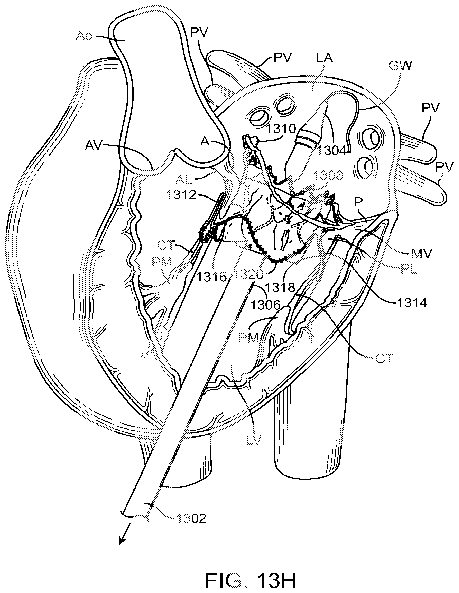
D00038

D00039

D00040

D00041
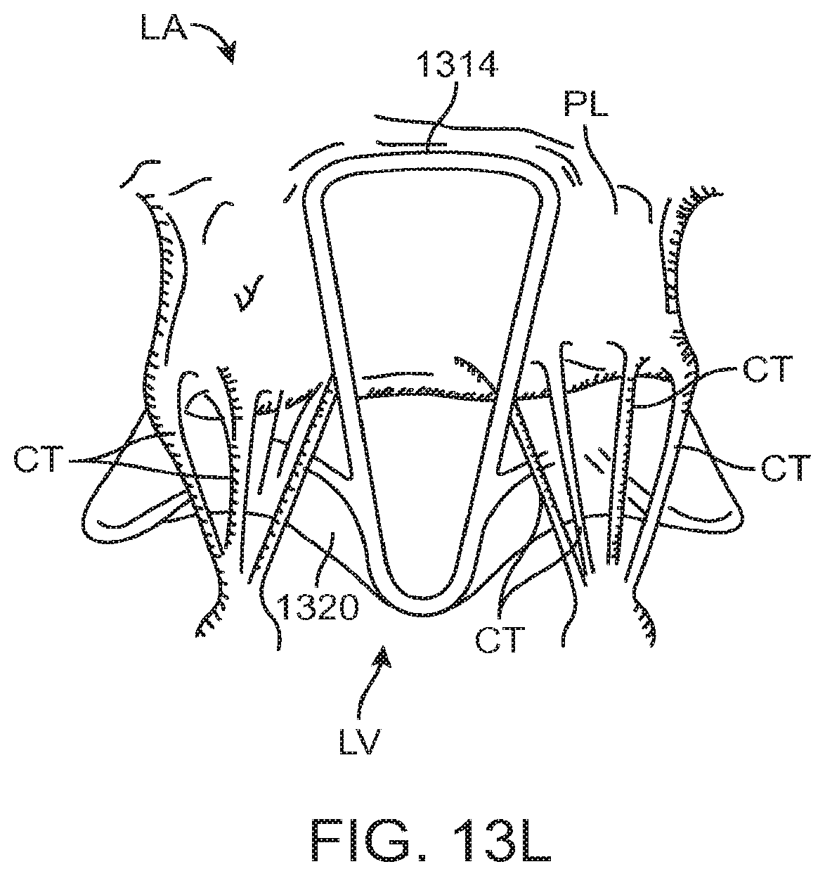
D00042

D00043

D00044

D00045

D00046

D00047

D00048

D00049
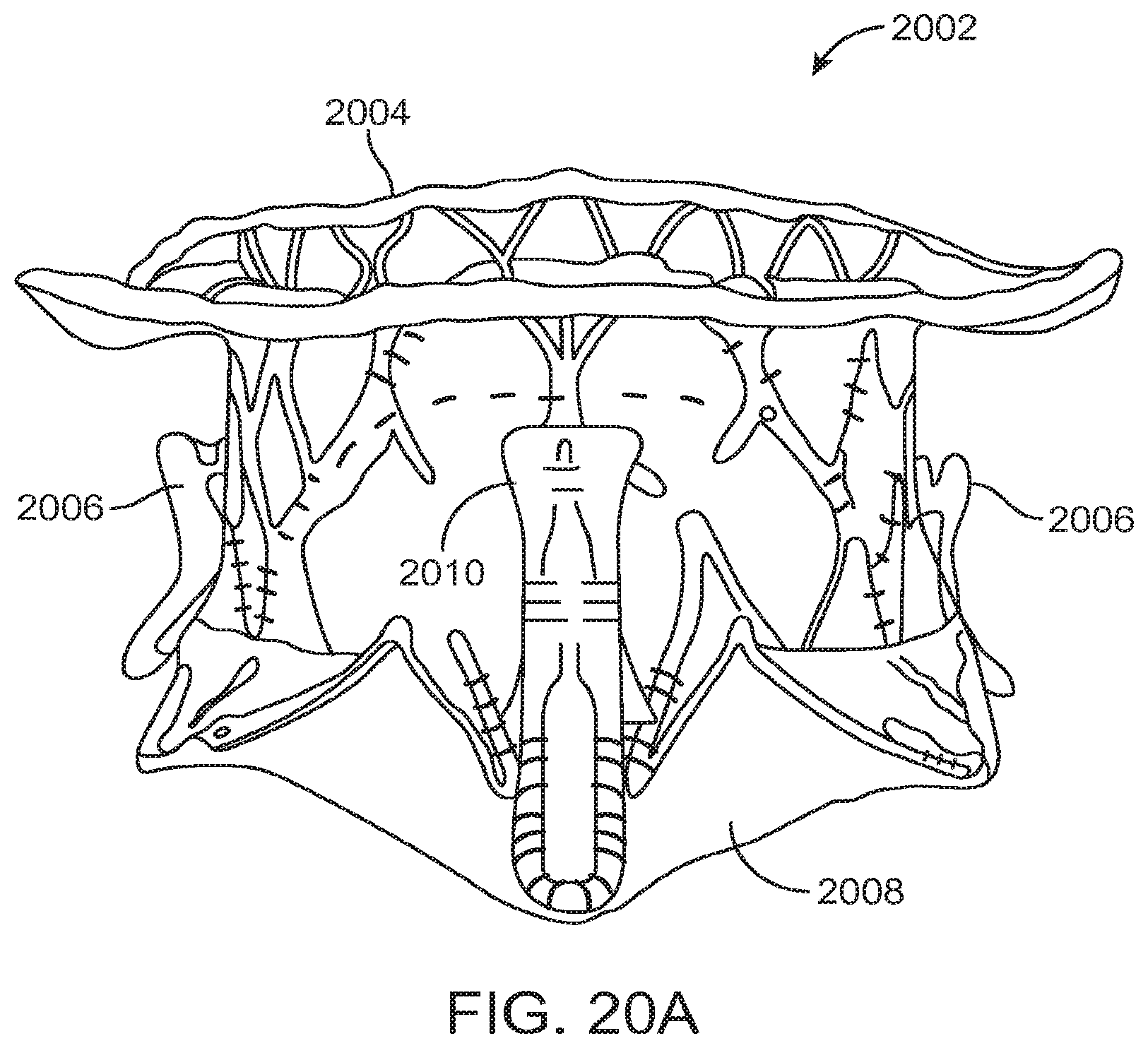
D00050

D00051

D00052

D00053

D00054

D00055

XML
uspto.report is an independent third-party trademark research tool that is not affiliated, endorsed, or sponsored by the United States Patent and Trademark Office (USPTO) or any other governmental organization. The information provided by uspto.report is based on publicly available data at the time of writing and is intended for informational purposes only.
While we strive to provide accurate and up-to-date information, we do not guarantee the accuracy, completeness, reliability, or suitability of the information displayed on this site. The use of this site is at your own risk. Any reliance you place on such information is therefore strictly at your own risk.
All official trademark data, including owner information, should be verified by visiting the official USPTO website at www.uspto.gov. This site is not intended to replace professional legal advice and should not be used as a substitute for consulting with a legal professional who is knowledgeable about trademark law.